Loading ...
Loading ...
Loading ...
INSTALLATION
Residen al Hybrid Electric Heat Pump Water Heater Use and Care Guide • 13
INSTALLATION
3
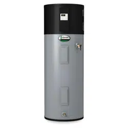
Terminate the discharge pipe
a maximum of six inches
above a fl oor drain or outside
the building. Do not drain the dis-
charge pipe into the drain pan; instead
pipe it separately to an adequate
drain. In cold climates, terminate the
discharge pipe inside the building to an
adequate drain. Outside drains could
freeze and obstruct the drain line.
Protect the drain from freezing.
DISCHARGE
PIPE
DRAIN
PIPE
Figure 17 - The end of the T&P Relief Valve
discharge pipe must stop no more than six
inches above a floor drain or outside.
4
Do not place any valve or
other restric on between the
tank and T&P Relief Valve. Do
not cap, block, plug, or insert any valve
between the T&P Relief Valve and the
end of the discharge pipe. Do not
insert or install any reducer in the
discharge pipe.
Step 8:
Install shutoff and
mixing valves
1
If one is not already installed,
install a manual shutoff valve
in the cold water line that
supplies the water heater. Install the
shutoff valve near the water heater so
that it is readily accessible. Only use
valves that are compa ble with
potable water. Use only full-fl ow ball
or gate valves. Other types of valves
may cause excessive restric on to the
water fl ow.
2
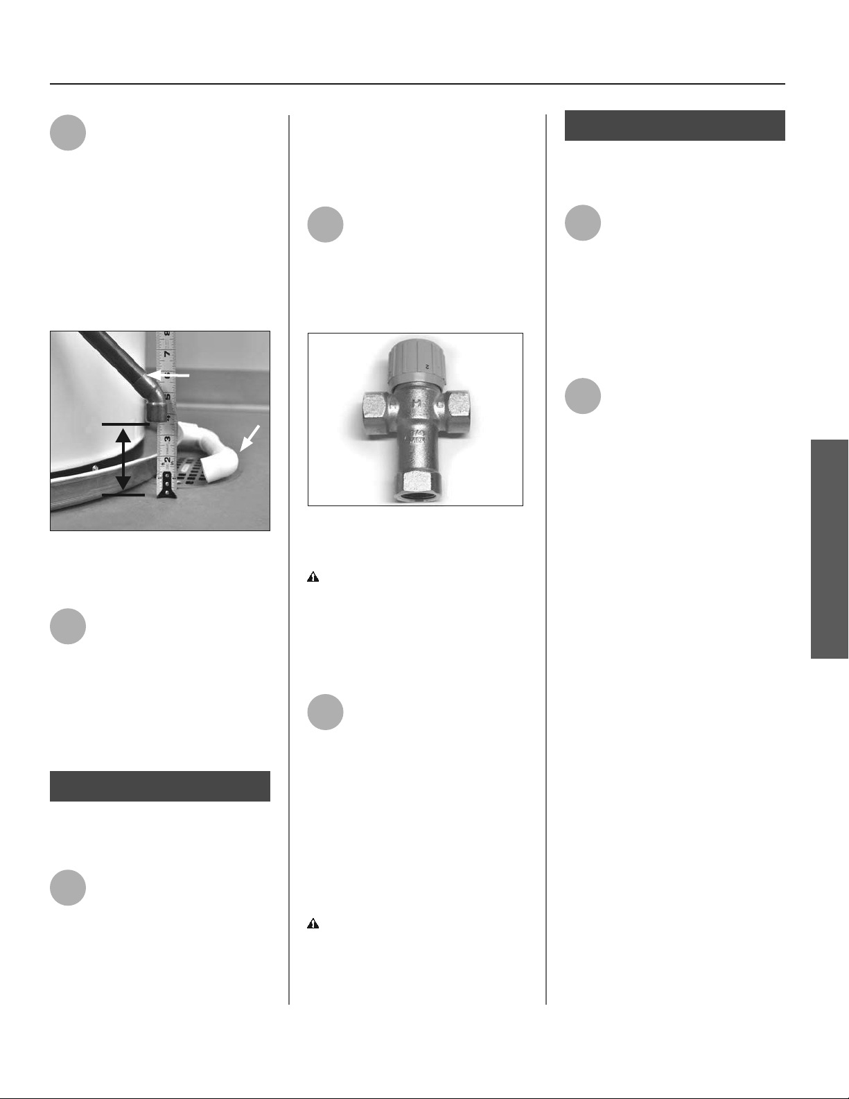
Install a Thermosta c Mixing
Valve at each point-of-use (for
example, kitchen sink,
bathroom sink, bath, shower). Consult
the valve manufacturer’s instruc ons
or a qualifi ed person.
Figure 18 - Install Thermostatic Mixing
Valves at each point where hot water will
be used.
WARNING! Even if the water
heater’s thermostat(s) are set to a
rela vely low temperature, hot water
can scald. Install Thermosta c Mixing
Valves at each point-of-use to reduce
the risk of scalding.
3
For water heaters that are fed
by a solar water hea ng
system (or any other pre-heat-
ing system), always install a Thermo-
sta c Mixing Valve or other tempera-
ture limi ng device in the inlet water
supply line to limit water supply inlet
temperature to 120°F. Solar water
hea ng systems can supply water with
temperatures exceeding 170°F and may
result in water heater malfunc on.
WARNING! Hot water provided by
solar hea ng systems can cause severe
burns instantly, resul ng in severe
injury or death (page 4).
Step 9:
Connect the water
supply
1
Determine the type of water
pipes in your home. Most
homes use copper water pipes,
but some use CPVC or cross-linked
polyethylene (PEX). Use fi ngs
appropriate for the type of pipe in your
home. Do not use iron or PVC pipe –
they are not suitable for potable water.
2
Connect the cold water supply
using 3/4 inch Na onal Pipe
Thread “NPT” to the blue cold
water connec on near the bo om of
the heater.
For ease of removing the water heater
for service or replacement, connect
the water pipes with a coupling
called a union. We recommend using
a dielectric-type union (available at
your local plumbing supplier ). Dielec-
tric unions can help prevent corro-
sion caused by tiny electric currents
common in copper water pipes and
can help extend the life of the water
heater.
Recircula ng Loop
In order to optimize efficiency of this
unit, it is not recommended for use
with a recirculation loop. Using this in
a recirculation loop may cause the unit
to run excessively.
Loading ...
Loading ...
Loading ...