Loading ...
Loading ...
Loading ...
W415-1517 / A / 09.02.16
18
EN
88.1A
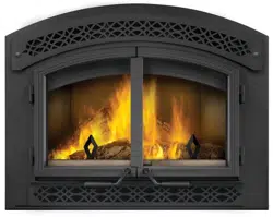
Remove the nails from the shingles above and to the sides of
the chimney. Place the fl ashing over the chimney pipe and slide
underneath the sides and upper edge of the shingles. Ensure that
the chimney pipe is properly centered within the fl ashing, giving
a 3/4” (19.1mm) margin all around. Fasten to the roof on the top
and sides. DO NOT NAIL through the lower portion of the fl ashing.
Make weather-tight by sealing with caulking. Where possible, cover
the sides and top edges of the fl ashing with roofi ng material. Apply
waterproof caulking, provided with the fl ashing, around the chimney,
1” (25.4mm) above the top of the fl ashing and push the storm collar
down into the caulking. Insert a rain cap onto the top of the last
chimney section.
RAIN CAP
CAULKING
STORM COLLAR
WEATHER
SEALANT
FLASHING
4.5 INSTALLING FLASHING AND STORM COLLAR
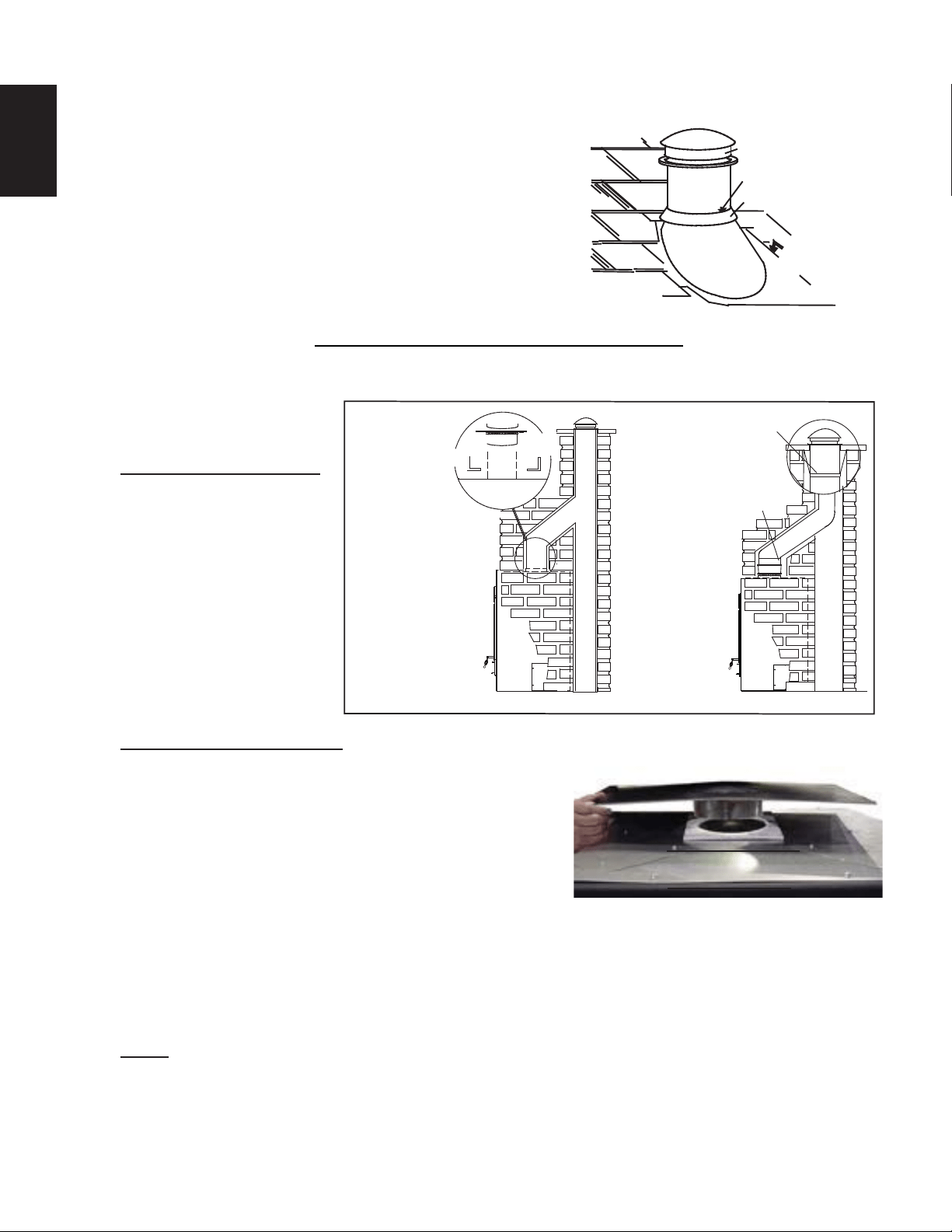
4.6 TYPICAL EXISTING MASONRY
The appliance may be connect-
ed to either a lined or unlined
masonry chimney.
IF THE CHIMNEY IS LINED:
The fl ues must be made of
vitrifi ed clay and be in sizes
of 8” (203.2mm) square or 8”
(203.2mm) round (inside di-
ameters) or 8”x12” [(203.2mm
x 304.8mm)] with a minimum
height of 15 feet (4.6m) above
the appliance.
8” (203.2mm) round fl ues are
recommended.
Installation must conform to
both national and local code
requirements.
IF THE CHIMNEY IS UNLINED:
A stainless steel liner listed to either Standard ULC-S640M in
Canada or UL-1777 in the USA, must be used: Liners for New
Masonry Chimneys, may be used to connect the appliance to
the chimney. The liner must be continuous from the appliance to
the chimney cap and be installed only per manufacturers instruc-
tions.
In both cases, the chimney structure must be supported by angle
iron anchored into the masonry walls. The allowable masonry
used in chimney construction is 3 1/2” (88.9mm) brick, solidly
mortared and must fully encase the fl ue. Ensure there are no
leaks.
In no case is the masonry enclosure to be supported by the appli-
ance. Allow a 1” (25.4mm) air cavity for expansion. Use the fl ue tile support accessory, see your local autho-
rized dealer / distributor.
NOTE: The fl ue tile support is to be suspended on appropriate lintels.
ANGLE IRON RESTS
ON BRICK SIDE-WALLS,
FREE OF UNIT.
FLUE TILE
HI-TEMP GASKET
ANGLE IRON TO SUPPORT
CHIMNEY WEIGHT
FLUE TILE
SUPPORT
APPLIANCE TOP
UNLINED CHIMNEY INSTALL
USE AN 7” (177.8mm)
OR 8" (203.2mm) LINER
WITH A DRIPLESS TYPE
A CONNECTOR
(IF USING 7” (177.8mm)
A 7” TO 8” INCREASER
FROM LINER TO FLUE
ALSO CAN BE USED.)
LINER
SUPPORT
LINED CHIMNEY INSTALL
HI-TEMP GASKET
FIREPLACE TOP
FOR A MASONRY FIREPLACE USE A
FLUE TILE SUPPORT. FOR A
PRE-FABRICATED CHIMNEY USE AN
ANCHOR PLATE.
Loading ...
Loading ...
Loading ...