Loading ...
Loading ...
Loading ...
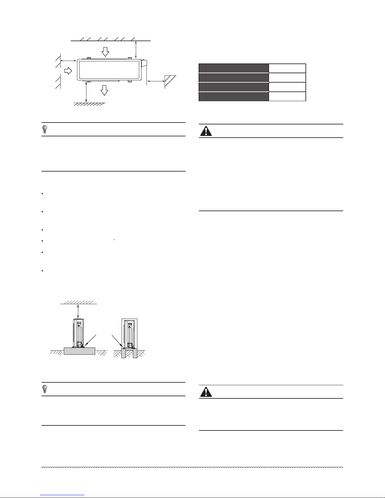
Fig.6-4
NOTE
CAUTION
>11.8in/
30cm
>23.6in/
60cm
>11.8in/
30cm
>78.7in/
200cm
(Wall or obstacle)
Air outlet
Air inlet
M
P
Air inlet
Maintain channel
N
Side air outlet outdoor unit
Fig.6-5
6.2 Moving and installation
All the pictures in this manual are for illustration
purposes only. They may differ slightly from the air
conditioner you purchased(depending on model).
NOTE
All the pictures in this manual are for illustration
purposes only. They may differ slightly from the air
conditioner you purchased(depending on the model).
Since the gravity center of the unit is not at its physical
center, be careful when lifting it with a sling.
Never hold the inlet of the outdoor unit to prevent it from
deforming.
Do not touch the fan with hands or other objects.
Do not lean the unit more than 45, and do not lay it sidelong.
Make a concrete foundation according to the specifications of
the outdoor units.(Refer to Fig.6-5)
Fasten the feet of this unit with bolts firmly to prevent it from
collapsing in case of earthquake or strong wind.(Refer to
Fig.6-5)
7. INSTALL THE CONNECTING PIPE
Check whether the height drop between the indoor unit and
outdoor unit, the length of refrigerant pipe, and the number of
the bends meet the following requirements:
All field piping must be provided by a licensed
refrigeration technician and must comply with the
relevant local and national codes.
Do not let air, dust, or other impurities fall in the pipe
system during the installation.
The connecting pipe should not be installed until the
indoor and outdoor units have been fixed already.
Keep the connecting pipe dry, and do not let moisture in
during installation.
Execute heat insulation work completely on both sides
of the gas piping and the liquid piping. Otherwise, this
can sometimes result in water leakage.
The Procedure of Connecting Pipes
7.1
Table 7-1
Capacity(Btu/h)
The max height drop
The length of refrigerant pipe
The number of bends
16.4ft/5m
Less than
32.8ft/10m
Less than 5
Fix with bolt
CAUTION
Drill a hole in the wall (suitable just for the size of the wall
conduit), then set on the fittings such as the wall conduit and
its cover.
Bind the connecting pipe and the cables together tightly with
binding tapes.
Pass the bound connecting pipe through the wall conduct
from outside. Be careful of the pipe allocation to avoid
damage to the tubing.
Connect the pipes. Refer to "How to Connect the pipes" for
details.
Expel the air with a vacuum pump. Refer to "How to expel the
air with a vacuum pump" for details.
Open the stop values of the outdoor unit to connect the
refrigerant pipe to the indoor unit with the outdoor unit in
fluent flow.
Check the leakage. Check all the joints with the leak detector
or soap water.
Cover the joints of the connecting pipe with the soundproof /
insulating sheath (fittings), and bind it well with tape to
prevent leakage.
1
2
3
5
6
7
4
Ensure that the insulating materials cover all the exposed
parts of the flare pipe joints and refrigerant pipe on the
liquid-side and the gas-side. Ensure there is no gap
between them.
Incomplete insulation may cause water condensation.
>23.6in/
60cm
9000~12000
9
Downloaded from www.ManualsFile.com manuals search engine
Loading ...
Loading ...
Loading ...