Loading ...
Loading ...
Loading ...
CAUTION
Additional Refrigerant Charge
7.2
Refrigerant cannot be charged until field wiring has been
completed.
Refrigerant may only be charged after performing the leak
test and the vacuum pumping.
When charging a system, care shall be taken that the
maximum permissible charge is not exceeded, in view of the
danger of liquid hammer.
Charging with an unsuitable substance may cause explosions
and accidents, so always ensure that the appropriate
refrigerant is charged.
Refrigerant containers shall be opened slowly.
Always use protective gloves and protect your eyes when
charging refrigerant.
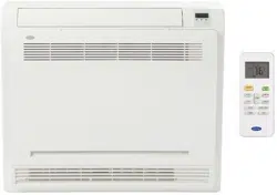
Fig.7-11
NOTE
Pressure meterMulti-meter
Lo-lever
Lo-lever
Charge hose Charge hose
Vacuum pump
Hi-lever
Manifold valve
If a negative result is received for R from the formula at
right, no refrigerant needs to be added nor removed.
The outdoor unit is factory charged with refrigerant. Some
systems require additional charging of refrigerant depending
on pipe lengths. The additional refrigerant to be charged can
be calculated from the following formule:
The standard pipe length will vary according to the requirements of
your area. For example, in North America area, the standard pipe
length is 25ft(7.5m). While in the other areas, the standard pipe
length is 16ft(5m).
Inverter R410A:
Liquid side:φ1/4"(6.35) (Total pipe length - standard pipe length)x0.16oZ(15g)/m(ft)
Liquid side:φ3/8"(9.52) (Total pipe length - standard pipe length)x0.32oZ(30g)/m(ft)
CAUTION
The drain pipe of indoor unit must be heat insulated, or it will
condense dew, as well as the connections of the indoor unit.
Hard PVC binder must be used for pipe connection, and make
sure there is no leakage.
With the connection part to the indoor unit, be sure not to
impose pressure on the side of indoor unit pipes.
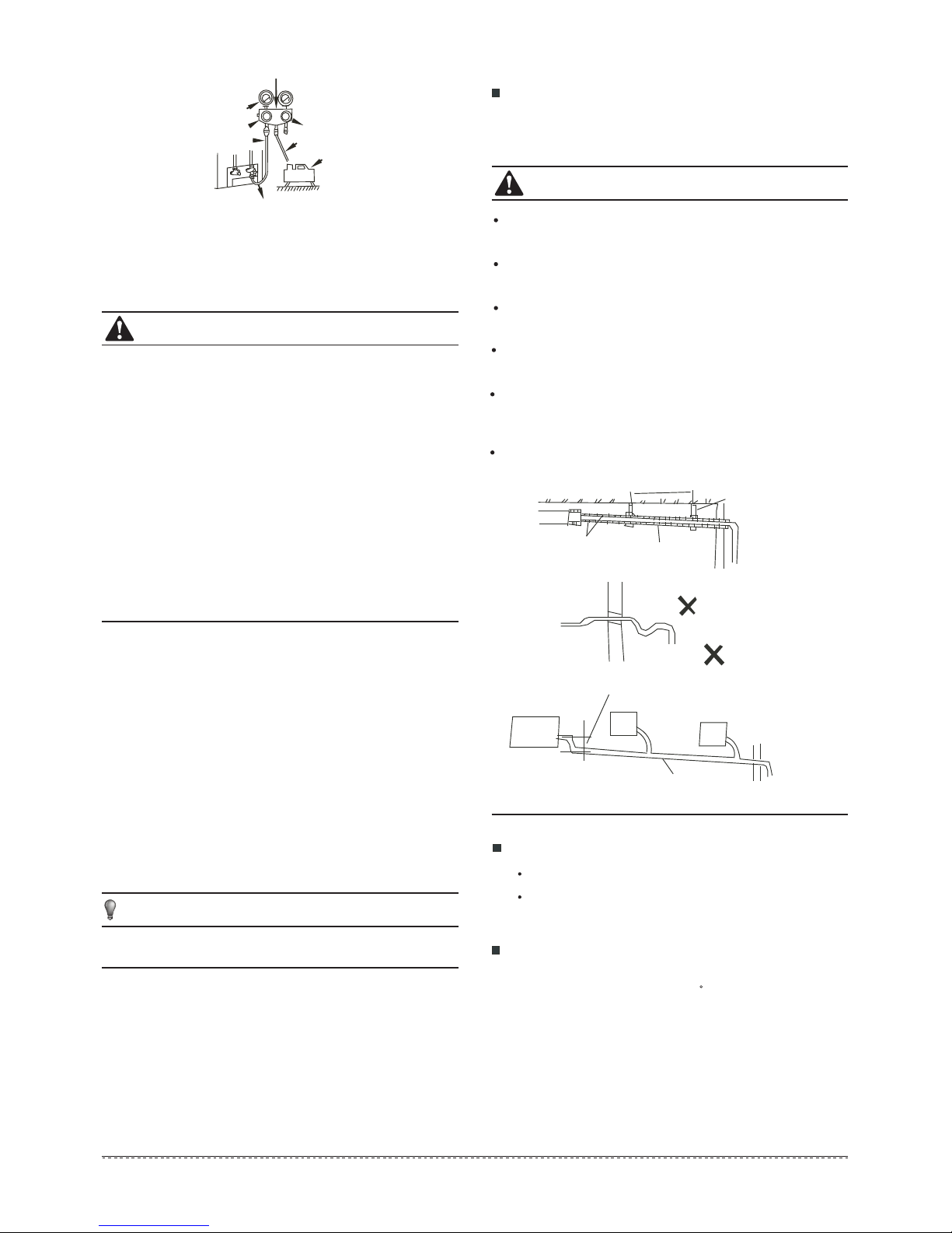
When the declivity of the drain pipe downwards is over 1/100,
there should not be any winding.
The total length of the drain pipe when pulled out traversely
shall not exceed 20m, when the pipe is over long, a prop stand
must be installed to prevent winding.
Refer to the figures on the right for the installation of the pipes.
8. CONNECT THE DRAIN PIPE
Install the drainpipe of the indoor unit
The outlet has PTI screw thread, Please use sealing materials
and pipe sheath(fitting) when connecting PVC pipes.
Drainage test
Ensure the drainpipe is unhindered.
The newly built housing should have this test preformed
before paving the ceiling.
4.9ft/1.5m~ 6.6ft/2m
Insulating
material
Downward declivity
lower than 1/100
Bend
S shape
VP30
Downward declivity
lower than 1/100
Put as deep as possible
(about 3.9in/10cm)
Fig. 8-1
Install the drain joint of the outdoor unit
Fit the seal into the drain joint, then insert the drain joint into the
base pan hole of outdoor, rotate 90 to securely assemble them.
Connect the drain joint with an extension drain hose (Locally
purchased), in case of the condensation draining off the outdoor
unit during the heating mode.(Refer to Fig.8-2)
-2.5ftHg/-76cmHg
12
Downloaded from www.ManualsFile.com manuals search engine
Loading ...
Loading ...
Loading ...