Loading ...
Loading ...
Loading ...
CAUTION
NOTE
NOTE
All the pictures in this manual are for illustration purposes only.
They may differ slightly from the air conditioner you
purchased(depending on model).
9. WIRING
The appliance shall be installed in accordance with
national wiring regualtions.
The air conditioner should use aseparate power supply
with rated voltage.
The external power supply to the air conditioner should
have a ground wiring, which is linked to the ground
wiring of the indoor and outdoor unit.
The wiring work should be done by qualified persons
according to circuit drawing.
An all-pole disconnection device which has at least 3mm
separation distance in all pole and a residual current
device(RCD)with the rating of above 10mA shall be
incorporated in the fixed wiring according to the national
rule.
Be sure to locate the power wiring and the signal wiring
well to avoid cross-disturbance.
Do not turn on the power until you have checked the
wiring carefully.
Remark per EMC Directive 89/336/EEC
To prevent flicker impressions during the start of the
compressor (technical process), the following installation
conditions apply.
The power connection for the air conditioner has to be
done at the main power distribution. The distribution must
have low impedance, normally the required impedance
reaches a 32 A fusing point.
No other equipment has to be connected with this power
line.
For detailed installation acceptance please refer to your
power supplier, for products like washing machines, air
conditioners or electrical ovens.
1
2
3
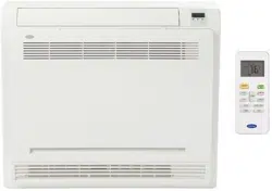
Seal
The base pan hole
of outdoor unit
Drain joint
Seal
The base pan
of outdoor unit
Drain
joint
Fig.8-2
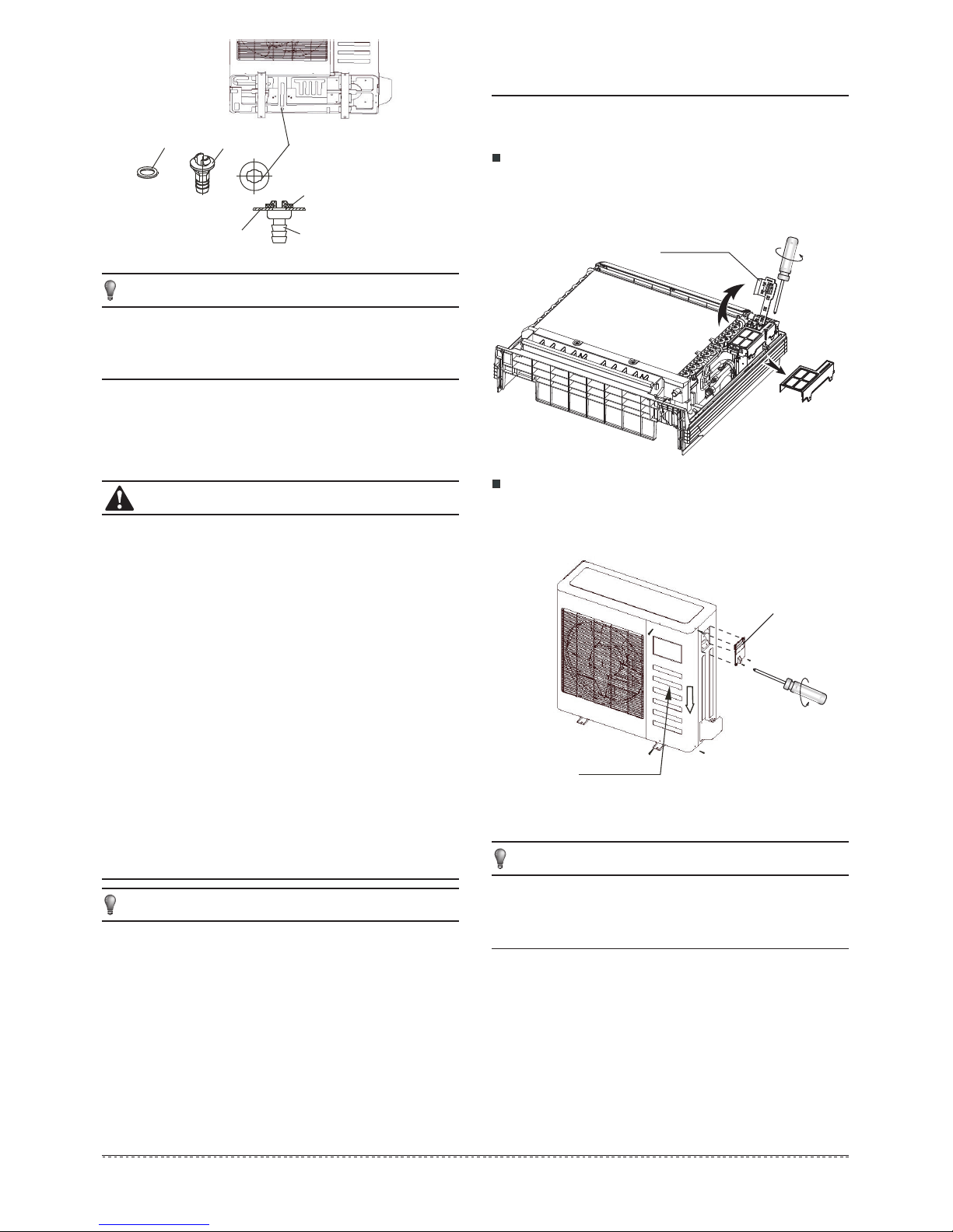
NOTE
Dissemble the bolts from the cover.(If there isn't a cover on
the outdoor unit, disassemble the bolts from the maintenance
board, and pull it in the direction of the arrow to remove the
protection board.)
(Refer to Fig.9-2)
Rotate the installation bearer of the sensing device to the
other side, and then take off the cover of electrical box. (Take
off the electrical box if the capacity is 18000btu/h and its
using the network function.)
(Refer to Fig.9-1)
Connect the cable
9.1
Fig.9-2
Protection board
Cover
For power details of the air conditioner refer to the rating
plate of the product.
If you have any questions, contact your local dealer.
4
5
All the pictures in this manual are for illustration
purposes only. They may differ slightly from the air
conditioner you purchased(depending on the model).
Installation bearer
of sensing device
Fig.9-1
13
Downloaded from www.ManualsFile.com manuals search engine
Loading ...
Loading ...
Loading ...