Loading ...
Loading ...
Loading ...
23
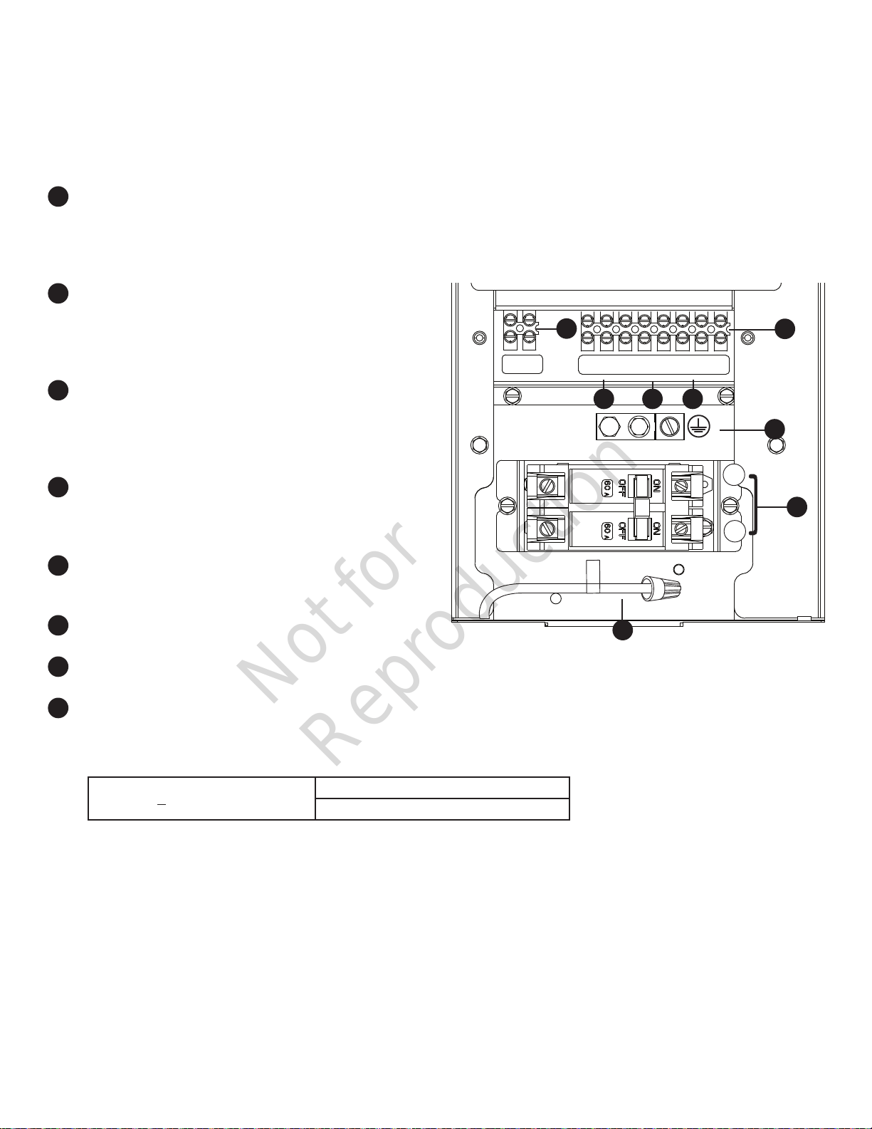
Low Voltage connections to signal fault contacts, transfer switch communication and auxiliary 12VDC power are made via a
field connection terminal block in control board area. Compare this illustration with your generator to familiarize yourself with
the location of these connections.
System Connectors
A
- Two Pin Terminal Block — Used to connect
utility 240 VAC from fuse block in ATS to the
control board. Connect only one wire per
terminal, Use #14 [2.5mm
2
] AWG minimum
300 volt wire.
B
- Fault Contacts — Use 1 (N.O.), 2 (COM)
and 3 (N.C.) to hook up a siren, light, etc. to
alert you in case of a fault. Contacts reverse
state (1 [N.O.] goes to 3 [N.C.] and vice versa)
upon a fault condition.
C
– Transfer Switch Communication (4 [TxRx]
and 5 [TxRx GND]) — Connect to transfer
switch control board for communication
interface using 18AWG [1mm
2
] twisted pair
wire.
D
– 6 (+LED) and 7 (GND) Connection — Not
required for wireless monitor included with
unit. Available for optional hardwired remote
system status panel accessory, #6154.
E
- Eight Pin Terminal Block — Used to
connect signal wires to the control board.
Connect only one wire per terminal.
F
- Power Connection (Line 1 and Line 2) —
Power connection to transfer switch.
G
- Ground Connection — Connect to transfer
switch ground wire.
H
- Neutral Connection — Connect to transfer
switch neutral wire
• For power output connection (Line 1, Line 2, Neutral, and Ground), refer to the following table:
• For transfer switch communication use #18 AWG [1mm
2
] twisted pair conductors, no greater than 200 ft in length,
300 volt wire.
• When connecting to the terminal block, fasten only one wire to each connector screw.
• Torque terminal block screws to 4.4 in-lb [0.49 Newton meter].
• Torque circuit breaker connections to 45 in-lb [5 Newton meter].
* Metric system rounded for simplicity
1
2
3
4
5
6
7
8
25
26
L1
L2
N
auto
off manual
ok
menu
esc
E
B
]
F
]
G
]
C
]
D
A
H
> 300V, 75° C
10 kW
6 AWG [13 mm
2
] min. Cu/Al
* Reference NEC 2014 table 310.15 • Use National Electric Code for correction factors and wire size calculations.
NOTICE Neutral wire (H) must be connected to
the transfer switch Neutral wire.
DO NOT connect neutral and ground together
within the generator.
Not for
Reproduction
Loading ...
Loading ...
Loading ...