Loading ...
Loading ...
Loading ...
_[wr_,1=t_'llKl[e_
To prevent personalinjury,always disconnect plug
from the power sourcewhen making any adjustment.
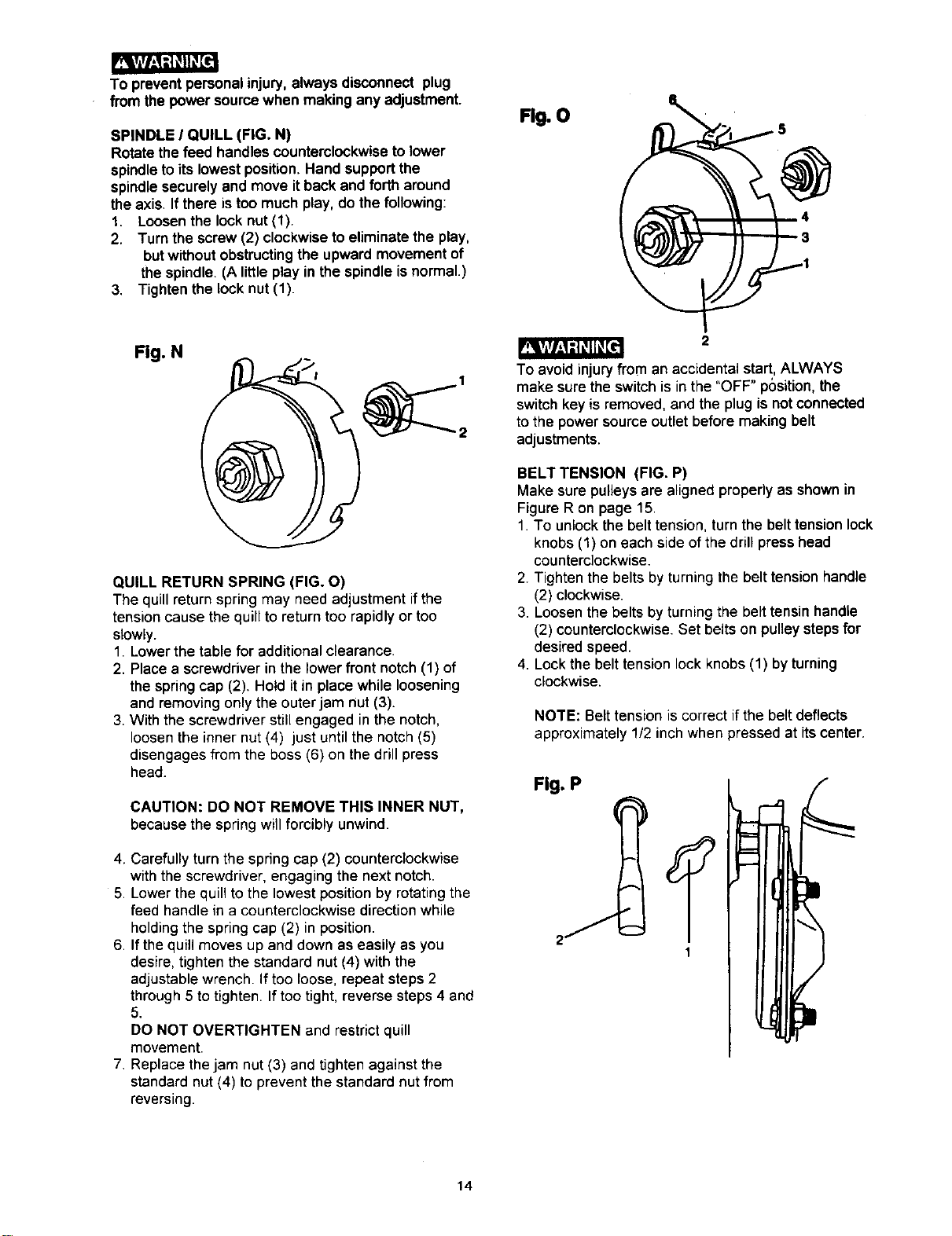
SPINDLE I QUILL (FIG. N)
Rotate the feed handles counterclockwiseto lower
spindleto its lowestposition.Hand supportthe
spindlesecurely and move itback and fortharound
the axis. If there is too much play,do the following:
1. Loosenthe lock nut(1).
2. Turn the screw (2) clockwiseto eliminate the play,
butwithoutobstructingthe upward movement of
the spindle. (A littleplay in the spindleisnormal.)
3. Tighten the lock nut(1).
Fig. O
Fig. N
QUILL RETURN SPRING (FIG. O)
The quillreturnspring may need adjustment ifthe
tensioncause the quillto returntoo rapidly or too
slowly.
1. Lowerthe table for additionalclearance.
2. Placea screwdriverin the lower front notch(1) of
the springcap (2). Hold it in place while loosening
and removingonlythe outerjam nut (3).
3. With the screwdriverstillengaged inthe notch,
loosenthe inner nut(4) just untilthe notch(5)
disengagesfrom the boss (6) on thedrillpress
head.
CAUTION: DO NOT REMOVE THIS INNER NUT,
because the springwill forcibly unwind.
4. Carefully turn the spring cap (2) counterclockwise
with the screwdriver, engaging the next notch.
5. Lower the quill to the lowest position by rotating the
feed handle in a counterclockwise direction while
holding the spring cap (2) in position.
6. If the quill moves up and down as easily as you
desire, tighten the standard nut (4) with the
adjustable wrench. If too loose, repeat steps 2
through 5 to tighten. If too tight, reverse steps 4 and
5.
DO NOT OVERTIGHTEN and restrict quill
movement.
7. Replace the jam nut (3) and tighten against the
standard nut (4) to prevent the standard nut from
reversing.
2
To avoidinjury from an accidental start, ALWAYS
make sure the switch is in the "OFF" position, the
switch key is removed, and the plug is not connected
to the power source outlet before making belt
adjustments.
BELT TENSION (FIG. P)
Make sure pulleysare alignedproperly as shown in
FigureR on page 15.
1. To unlockthe belt tension,turnthe belt tensionlock
knobs (1) on each side of the drillpresshead
counterclockwise.
2. Tightenthe belts by turningthe belt tension handle
(2) clockwise.
3. Loosenthe beltsby turning the belt tensinhandle
(2) counterclockwise.Set belts on pulleystepsfor
desired speed.
4. Lockthe belt tensionlockknobs(1) byturning
clockwise.
NOTE: Belt tension is correct ifthe belt deflects
approximately 1/2 inch when pressed at itscenter.
Fig. P
14
Loading ...
Loading ...
Loading ...