Operator's Manual
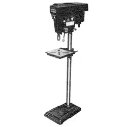
1 HP (Maximum Developed)
12 Speeds (250-3100 R.P.M.)
5/8 Inch Chuck
15-INCH DRILL PRESS
Model No,
137.229151
CAUTION:
Before using this Drill Press,
read this manual and follow
all its Safety Rules and
Operating Instructions
• Safety Instructions
• Installation
• Operation
• Maintenance
• Parts List
• EspaSol
Customer Help Line
1-800-843-1682
Sears, Roebuck and Co., Hoffman Estates, IL 60179 USA
Visit our Craftsman website: www.sears.comlcraftsman
Part No. 137229151001
SECTION PAGE
Warranty ................................................................................................................ 2
Product Specificattone ............................................................................................. 2
Safety Instructions .................................................................................................. 3
Accessories and Attachments .................................................................................. 6
Carton Contents ...................................................................................................... 6
Know Your Drill Press ............................... _.............................................................. 8
Glossary of Terms ....................................................................... ;........................... 9
Assembly and Adjustment ..................................................... _...................... ,............ 10
Operation ............................................................................................................... 15
Maintenance ........................................................................................................... 20
Troubleshooting Guide ............................................................................................ 21
Parts ...................................................................................................................... 22
Espafiol ............................................................ ;..................................................... 25
FULL ONE YEAR WARRANTY
If this Driss Press fails due to a defect in material or workmanship within one year of date of purchase,
Sears will at its option repair or replace it free of charge.
Return this Drill Press to a Sears Service Center for repair, or to place of purchase for replacement.
This warranty gives you specific legal rights, and you may also have other rights which may vary from
state to state.
Sears, Roebuck and Co., Dept. 817 WA, Hoffrnan Estates, IL 60179
_q
Some dust created by power sanding, sawing, grinding, drilling and other construction activities contains
chemicals known to the state of California to cause cancer, birth defects or other reproductive harm. Some
examples of these chemicals are:
• Lead from lead-based paints
• Crystalline silica from bricks, cement and other masonry products
• Arsenic and chromium from chemicallytreatsd lumber
Your risk from these exposures varies, depending on how often you do this type of work. To reduce )/our
exposure to these chemicals work in a well-ventnated area and work with approved safety equipmentsuch as
dust masks that are spec a y des gned to filter out microscopic particles.
Chuck Size ............................ 5/8"
Speed ................................... 12 (250 ~ 3,100 RPM)
Motor .................................... 120V, 60 Hz, 8 Amps
Horsepower ........................... 1 HP (Max. Developed)
Built-in Light ......................... 60 Watt (Maximum)
(Bulb not included)
Table Size ............................ 13-1/4" x 13-1/4"
Table Tilt ............................... 45 ° Right or Left
Spindle Travel ........................ 3-1/8"
Throat ................................. 7-1/2"
Base Size ............................. 11" x 20-3/8"
Height ...................... :........... 63-1/4"
To avoid electrical hazards, fire hazards, or damage to
the tool, use proper circuit protection.
Your drill press iswired at the factory for 120V operation.
Connect to a 120V, 15 AMP branch circuit and use a 15
AMP time delay fuse or circuit breaker. To avoid shock or
fire, replace power cord immediately if it is worn, cut or
damaged in any way.
2
GENERAL SAFETYINSTRUCTIONS 14.
BEFORE USING THE DRILL PRESS
Safety is a combination of common sense, staying alert
and knowing howto use your ddll press. 15.
REMOVE ADJUSTING KEYS AND WRENCHES.
Form the habitof checking to see that keys and
adjusting wrenches are removed from the tool before
turning =ON".
NEVER LEAVETOOL RUNNING UNATFENDED.
TURN THE POWER "OFF". Don't leave the tooluntil
itcomes to a complete stop.
To avoid mistakes that could cause sedous injury, do not 16. NEVER STAND ON TOOL Sedous injurycould occur
plug the drillpress in until you have read and understood ifthe toolisUppedor ifthe cuffingtoolis unintentionally
the following: contacted.
1. READ and become familiar with this entire instruction
manual.LEARN thetool'sapplications,limitstJons,and
possiblehazards.
2. KEEP GUARDS IN PLACE and in workingorder.
3. DON'T USE IN A DANGEROUS ENVIRONMENT.
Don't use power tools in damp or wet locations, or
expose them to rain. Keep work area well lighted.
4. DO NOT use powertoolsin the presence offlammable
liquidsor gases.
5. KEEP WORK AREA CLEAN. Cluttered areas and
benches inviteaccidents.
6. KEEP CHILDREN AWAY.AUvisitorsshouldbe keptat
a safe distance from the work area.
7. DON'T FORCE THE TOOL. It Willdo the job better
and safer at the rate for which it was designed.
8. USETHE RIGHTTOOL. Don't force tool or the
attachment to do a job for which it was not designed.
.
WEAR PROPER APPAREL DO NOT wear loose
clothing, gloves, neckties, rings, bracelets, or other
_lowelrywhich may get caught in moving parts.
onslip footwear is recommended. Wear protective
hair covering to contain long hair.
10. WEAR A FACE MASK OR DUST MASK.
Drillingoperation produces dust.
11. DISCONNECTTOOLS before servicing, and when
changing accessories, such as blades, bits, ct_ttem,
and the like.
12. REDUCETHE RISK OF UNINTENTIONAL STARTING.
Make sure the switch is in "OFF"position before
plugging in.
13. USE RECOMMENDED ACCESSORIES. Consult the
owner's manual for the recommended accessories.
The use of improper accessories may cause risk of
injury to persons.
17. DON'T OVERREACH. Keep proper footing and
balance at all times.
18. MAINTAIN TOOLS WITH CARE. Keep toolssharp
and clean for best and safest performance. Follow
instructionsfor lubricating and changing accessories,
19. CHECK FOR DAMAGED PARrs. Beforefurther useof
the tool,a guard or otherpert that is damaged should
be carefully checked to determine that it willoperate
propertyand perform its intended function.Check for
alignmentof movingparts,bindingof moving parts,
breakage of parts, mounting,and any otherconditions
that may affect itsoperation.A guard or other part that
is damaged shouldbe properly repairedor replaced.
20. MAKEWORKSHOP laD PROOF withpadlocks,master
switches,or by removing starter keys.
21.
22.
DO NOT operatethe toolif you are underthe influence
of any drugs,alcohol or medication that could affect
your abilityto use the tool properly.
Dust generated from certain materials can be
hazardous to your health. Always operate the drill
press in a well-ventilated area and provide for proper
dust removal. Use dust coflectionsystems whenever
possible.
23. ALWAYS WEAR EYE
PROTECTION. Any ddll press
can throw foreignobjects into
the eyes which could cause
permanent eye damage.
ALWAYSwearSafety Goggles
(not glasses) thatcomplywith
ANSI safety standard Z87.1. Everyday eyeglasses
have only impact-resistant lenses. They ARE NOT
safety glasses.Safety Goggles are available at Seam.
NOTE: Glasses or goggles not in compliance with
ANSI Z87.1 could seriouslyhurtyou when they break.
SAVE THESE INSTRUCTIONS
3
SPECIFIC SAFETY INSTRUCTIONS
FOR THE DRILL PRESS
14.SECURE WORK. Usa clamps or viseto holdthe
work when practical.It'ssafer than using yourhand
and itfrees bothhandsto operatetool,
For yourownsafety,do nottry to use yourdrillpress or
plug itin untilit iscompletelyassembledand installed
accordingtothe instructions,and untilyou have read
and understoodthis instrucbonmanual:
15.WHEN usinga drillpressvise, always fastentothe
table.
16.MAKE SURE allclamps and locksare firmly
tightenedbeforedrilling.
1. YOUR DRILL PRESS MUST BE BOLTED securely
to a workbench. In addition,ifthere is anytendency
for yourdrillpressto move duringcertainoperations,
boltthe workbenchtothe floor.
2. THIS DRILL PRESS isintendedfor usa indry
conditions,indooruseonly.
3. WEAR EYE PROTECTION. USE face or dustmask
alongwithsafety gogglesifdrillingoperation isdusty.
USE ear protectors,especially duringextended
periodsofoperation.
4. DO NOT wear gloves, neckties,or looseclothing
5. DO NOT tryto drillmaterial too smallto be securely
held.
6. ALWAYS keephands out ofthe path of a drillbit.
Avoidawkward hand positionswhere a sudden slip
couldcause yourhandto move intothedrillbit.
7. DO NOT installor use any drill bit thatexceeds 175
mm (7") in lengthor extends 150 mm (6") below
thechuckjaws. They can suddenlybendoutwardor
break.
8. DO NOT USE wire wheels, router bits, shaper cutters,
circle(fly)cutters,or rotaryplanerson thisdrillpress.
17.SECURELY LOCK THE HEAD and table supper to
the column, and thetable to the table supportbefore
operatingthe drillpress.
18.NEVER turnyourdrillpresson beforeclearingthe
table of allobjects (tools,scrapsof wood, etc.)
19.BEFORE STARTING the operation,jog the motor
switchto make sure the drillbitdoes notwobbleor
vibrate.
20.LET THE SPINDLE REACH FULL SPEED before
startingtodrill.If yourdrillpress makes an unfamiliar
noiseor if itvibratesexcessively,stop immediately,
turnthe drillpress offand unplug.Do not restartuntil
the problemiscorrected.
21.DO NOT perform layoutassembly or set up work on
the tablewhilethe drill press isin operation.
22.USE RECOMMENDED SPEED for drill accessory
and workpiecematerial. SEE INSTRUCTIONS that
comewiththe accessory
23.WHEN DRILLING largediameter holes,clamp the
workpiece firmlytothe table. Otherwise, the bitmay
grapand spinthe workpieceat high speed. DO NOT
USE flycuttersor multiple-parf hole cutters,as they
cancome apart or become unbalancedin use.
9. WHEN cuttinga largepiece ofmaterial make sure it
isfully supportedat the table height.
24.MAKE SURE the spindle has come to a complete
stop before touching the workpiece.
10.DO NOT perform any operation freehand. ALWAYS
holdtheworkpiece firmly againstthe table so itwill
notreckor twist. Use clamps or a visefor unstable
workpiece.
11.MAKE SURE there are no nailsor foreign objectsin
the partofthe workpieceto be drilled.
12.CLAMP WORKPIECE OR BRACE against the left
side ofthe columnto prevent rotation.Ifit is too short
or thetable istilted, clamp solidlyto the table and use
the fence provided.
25.TO AVOID INJURY from accidental starting,always
turnthe switch"OFF" and unplugthe drill press
beforeinstallingor removing any accessoryor
attachmentor makingany adjustment
26.KEEP GUARDS IN PLACE and inworkingorder.
27.USE ONLY SELF-EJECTING TYPE CHUCK KEY as
providedwiththedrill press
13.IF THE WORKPIECE overhangs the table such that
it will fall or tip if not held, clamp it to the table or
provide auxiliary support.
SAVE THESEINSTRUCTIONS
GROUNDING INSTRUCTIONS
IN THE EVENT OF A MALFUNCTION OR
BREAKDOWN, groundingprovidesa path of least
resistancefor electriccurrentand reducesthe riskof
shock.Thistoolis equipped withan electriccordthat
hasan equipmentgroundingconductorand grounding
plug.The plugMUST be pluggedintoa matching
receptacle that isproperlyinstalledand grounded in
accordancewithALL localcodesand ordinances.
DO NOT MODIFY THE PLUG PROVIDED. If it willnotfit
the receptacle,have the properreceptacleinstalledbya
qualifiedelectdcian.
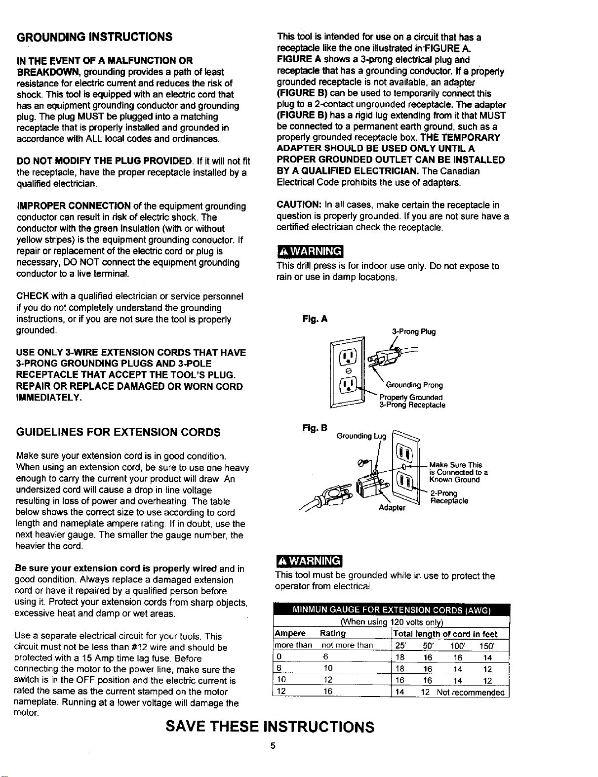
Thistoolis intendedfor use on a circuitthathas a
receptaclelike theone illustratedin'FIGURE A.
FIGURE A shows a 3-prongelectricalplug and
receptaclethathas a groundingconductor.Ifa pmparly
groundedreceptacle isnotavailable,an adaPter
(FIGURE B) can be usedto temporarilyconnectthis
plugto a 2-contact ungroundedreceptacle.The adapter
(FIGURE B) hasa rigidlugextendingfrom itthatMUST
be connectedtoa permanent earth ground,such as a
properlygrounded receptacle box. THE TEMPORARY
ADAPTER SHOULD BE USED ONLY UNTIL A
PROPER GROUNDED OUTLET CAN BE INSTALLED
BY A QUALIFIED ELECTRICIAN. The Canadian
ElectricalCode prohibitsthe use of adapters.
IMPROPER CONNECTION oftheequipmentgrounding
conductorcan result inrisk ofelectricshock.The
conductorwiththe green insulation(withor without
yellowstripes)isthe equipmentgroundingconductor.If
repair or replacementofthe electriccordor plug is
necessary,DO NOT connectthe equipmentgrounding
conductorto a liveterminal.
CHECK with a qualified electrician orservice personnel
ifyou do notcompletelyunderstandthegrounding
instructions,or ifyou are notsure the toolisproperly
grounded.
USE ONLY 3-WIRE EXTENSION CORDS THAT HAVE
3oPRONG GROUNDING PLUGS AND 3-POLE
RECEPTACLE THAT ACCEPT THE TOOL'S PLUG.
REPAIR OR REPLACE DAMAGED OR WORN CORD
IMMEDIATELY.
CAUTION: In all cases, make certainthe receptaclein
questionisproperlygrounded. Ifyou are notsure have a
certifiedelectriciancheckthe receptacle.
This drill press is for indoor use only. Do not expose to
rain or use in damp locations.
Flg. A
3-Prong Plug
_" p.rGprroP_o°nl_;_o_nrin;e
GUIDELINES FOR EXTENSION CORDS
Fig. B
GroundingLug
Make sure yourextension cord is ingood condition.
When usingan extensioncord, be sure touse one heavy
enoughtocarrythe current yourproductwilldraw. An
undersizedcordwillcause a dropin line voltage
resultingin lossof powerand overheating.The table
belowshowsthecorrectsize to use accordingtocord
length and nameplate ampere rating. Ifin doubt, usethe
nextheaviergauge. The smallerthe gauge number,the
heavierthecord.
Adapter
is Connected to a
Known Ground
Be sure your extension cord is properly wired and in
goodcondition.Always replace a damaged extension
cordor have itrepaired by a qualifiedperson before
usingit. Protectyourextensioncordsfrom sharpobjects,
excessiveheatand damp or wet areas
rdI_hV_lll_[e_-*ll[el naal] :s :1,:(ii :1_K'I[el _ [l(e] _| i},.llr:t tjLt/t.
Use a separate electrical circuit for your tools. This
circuit must not be less than #12 wire and should be
protected with a 15 Amp time lag fuse. Before
connecting the motor to the power line, make sure the
switch is in the OFF position and the electric current is
rated the same as the current stamped on the motor
nameplate. Running at a lower voltage will damage the
motor.
This tool mustbe grounded while in useto protect the
operator from electrical.
(When usinc
6,mpere Rating
more than not more than
0 6
6 10
10 12
12 16
SAVE THESE INSTRUCTIONS
120 volts only)
Total length of cord in feet
25' 50' 100' 150'
18 16 16 14
18 16 14 12
16 16 14 12
14 12 Not recommended
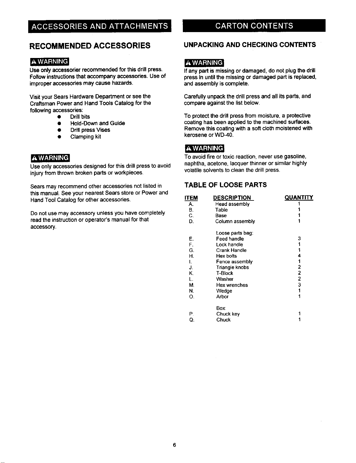
RECOMMENDED ACCESSORIES UNPACKING AND CHECKING CONTENTS
r_r/_J=-KqKE=]
Use onlyaccessorierrecommended for this drillpress.
Followinstructionsthataccompany accessories.Use of
improperaccessoriesmay cause hazards.
VisityourSears Hardware Department or see the
CraftsmanPower and Hand Tools Catalog for the
following accessories:
• Drillbits
• Hold-Downand Guide
• DrillpressVises
• Clamping kit
Ifany part ismissingor damaged, do not plugthe drill
pressin untilthe missingor damaged part isreplaced,
and assemblyiscomplete.
Carefullyunpackthe drill press and all itsparts,and
compare againstthe list below.
To protectthe drillpress from moisture,a protective
coatinghasbeen appliedtothe machinedsurfaces.
Remove thiscoating with a softclothmoistenedwith
keroseneor WD-40.
.r_rArl,_1d_11_[e
Use onlyaccessoriesdesigned for this drill pressto avoid
injuryfrom thrownbrokenparts or workpieces.
Sears may recommend otheraccessoriesnot listedin
this manual. See your nearest Sears store or Power and
Hand Tool Catalog for other accessories.
Do not use may accessoryunless you have completely
readthe instruction or operator'smanual for that
accessory.
To avoidfire or toxic reaction, never use gasoline,
naphtha,acetone, lacquerthinneror similarhighly
volatilesolventstoclean the drillpress.
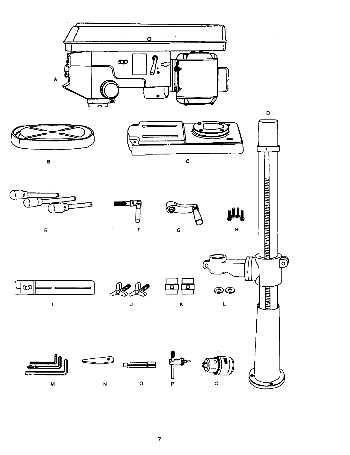
TABLE OF LOOSE PARTS
ITEM DESCRIPTION QUANTITY
A. Head assembly t
B. Table 1
C. Base 1
D. Column assembly 1
Loose partsbag:
E. Feed handle
F. Lock handle
G. Crank Handle
H. Hex botts
I. Fence assembly
J. Triangle knobs
K. T-Block
L, Washer
M. Hex wrenches
N. Wedge
O. Arbor
Boxz
P. Chuckkey
Q. Chuck
3
1
1
4
1
2
2
2
3
1
1
8
I
0
7
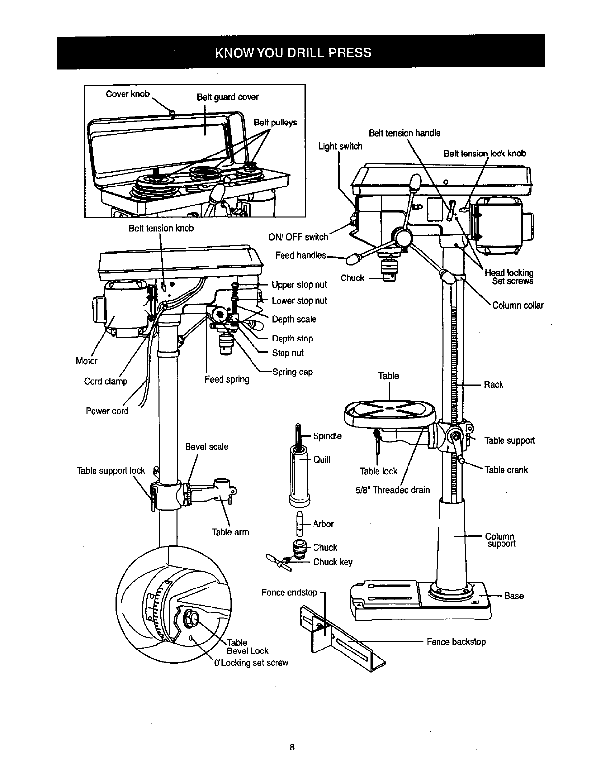
Coverknob
\
Beltguardcover
Beltpulleys
Lightswitch
Belttensionhandle
Belttensionlock knob
Belttensionknob
Motor
Cordclamp
Power cord
Table support I(
Feedspring
Bevelscale
• Upperstopnut
- Lowerstopnut
Depthscale
Depthstop
Stopnut
Springcap
-- Spindle
• Quill
Table
Tablelock
5/8"Threadeddrain
Set screws
Tablesupport
Tablearm
-.-Arbor
(_Chuck
Chuckkey
Column
support
Fenceend_\
BevelLock V _"_,,_
)'Locking setscrew
Fencebackstop
BASE - Supportsdrillpress.For additionalstability,
holesare providedin base toboltdrillpressto floor.
(See "Specific Safety Instruction for DrillPresses.")
BACKUP MATERIAL - Apiece ofscrapwood placed
betweenthe workpieceand table. The backupbeard
preventswood in the workpiecefrom splintedngwhen
the drillpassesthroughthe backsideoftheworkpiece.It
alsopreventsdrillingintothe table top.
BELT GUARD ASSEMBLY - Covers the pulleysand
beltduringoperationof the drillpress.
BELT TENSION - Refer to the"Assembly" Section,
"Installingand Tensioning Belt.".
BELT TENSION HANDLE - Turn thehandle clockwise
toapply tensionto belt, turnthe handle counterclockwise
to release belttension.
BELT TENSION LOCK KNOBS - Tighteningthe knobs
locksthemotorbracket supportand the belttension
handle,maintainingcorrectbeltdistanceand tension.
BEVEL SCALE - Shows degree of table tilt for bevel
operaions. The scale ismounted on the side ofthe arm.
CHUCK - Holdsdrill bit or otherrecommended
accessoryto performdesired operations.
CHUCK KEY - A self-ejectingchuckkey whichwillpop
outofthe chuckwhen you let go of it.This actionis
designedto help preventthrowingofthe chuck keyfrom
thechuckwhen the peer isturned ON. Do not useany
otherkey as a substitute; ordera newone if hamaged or
lost.
COLUMN - Connects the head, table, and base on a
one piecetube for easy alignment and movement.
COLUMN COLLAR - Holds the rack to the column.
Rack remains movablein the collarto permit table
support movements.
COLUMN SUPPORT - Supports the column, guides the
rack and providesmountingholesfor columnto base.
DEPTH SCALE STOP NUTS - Lock the spindle to the
selected depth.
DEPTH SCALE - Indicates depth of hole being drilled.
DRILL BIT - The cutting tool used in the drill press to
make holes in a workpiece.
DRILL ON/OFF SWITCH - Has lockingfeature. This
feature is intended to help preventunauthorizedand
possible hazardous use by children and others. Insert
the key into the switch to turn the drill press on.
DRILLING SPEED - Changed by placingthe belt in any
of the steps(grooves) inthe pulleys.See the Spindle
Speed Chart insidebeltguard.
FEED HANDLE - Moves the chuckup or down.IF
necessary, one ortwo ofthe handles may be removed
whenevertheworkpiece isof suchunusualshape thatit
interfereswith thehandles.
FENCE - Attaches tothe table to alignthe workpieceor
for fast repetitivedrilling.Removable. Removefence
when itinterfereswith otherdrillpress accessories.
HEAD LOCKS - Locks the head tothe column.
ALWAYS lockthe head in placewhile operatingthedrill
press.
RACK - Combines withgear mechanism to provide
easy elevationofthe table by thehandoperated table
crank.
REVOLUTION PER MINUTE (R.P.M.)- The numberof
turns completedbya spinningobjectin one minute.
SPINDLE SPEED - The RPM. ofthe spindle.
SPRING CAP - Adjusts quill spring tension.
TABLE SUPPORTS LOCK - Tighteninglocksthe table
supporttocolumn.Always haveit lockedin placewhile
operatingthe dirllpress.
TABLE - Provides a working surface to supportthe
workpiece.
TABLE ARM - Extends beyond the table supportfor
mounting and aligning the table.
TABEL BEVEL LOCK - Locks the table in anyposition
from 0° - 45°
TABLE CRANK - Elevates and lowers the table. Turn
clockwise to elevate the table. Support lock must be
released before operating the crank.
TABLE LOCK - Locksthe table after it is rotated to
variouspositions.
TABLE SUPPORT - Rides on the column to supportthe
table arm and table.
THREADED DRAIN (518")- Attach a 5/8" (pipe
threaded) metal pipe to the threaded opening for
drainingexcees oilintocontainer.Fora non-draining
surfaceattacha threaded metal plug.Pipe and plugnot .
included.
WORKPIECE - Material being drilled.
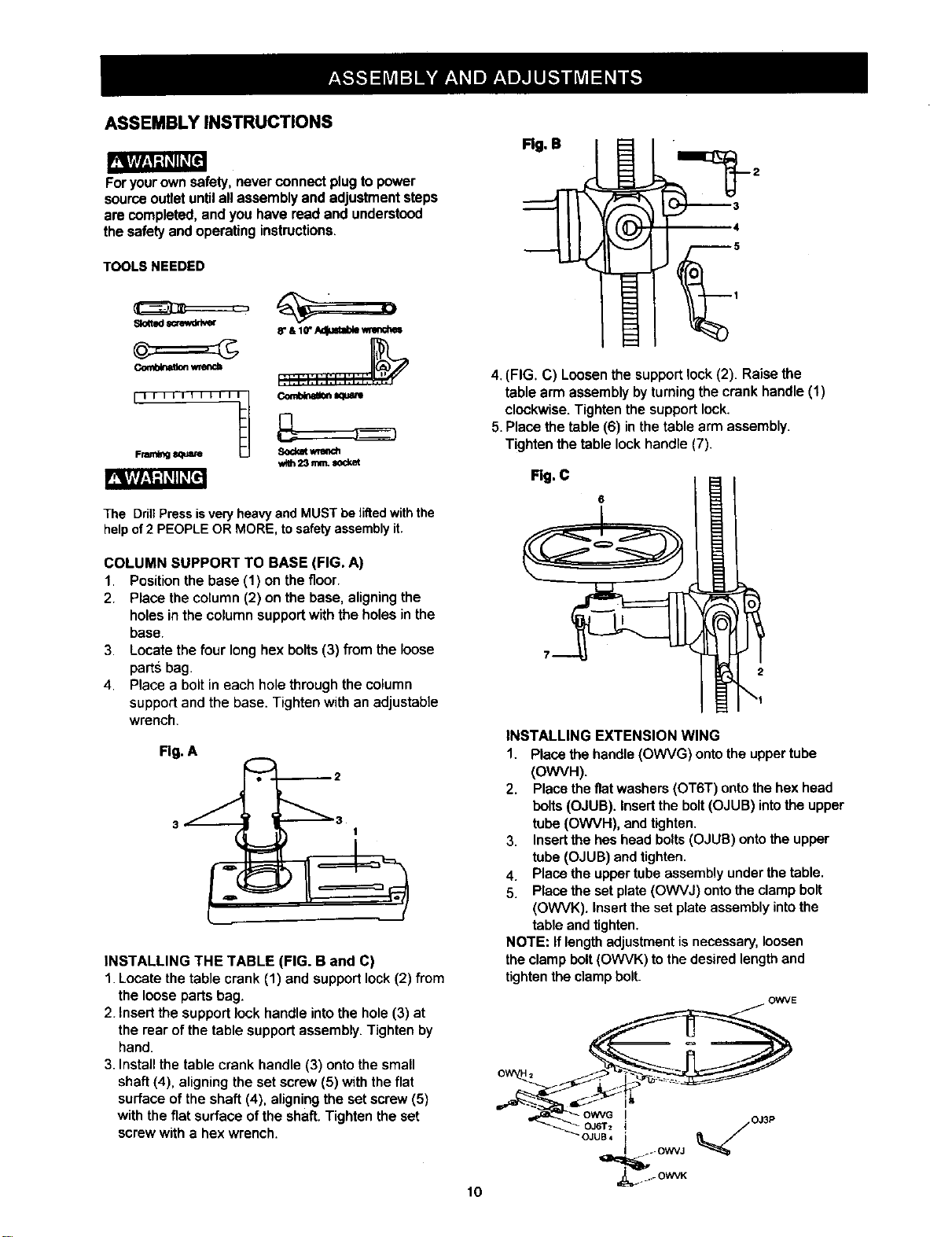
ASSEMBLY INSTRUCTIONS
Foryourownsafety,neverconnectplugtopower
sourceoutletuntilall assemblyand adjustmentsteps
arecompleted, andyou havereadand understood
the safetyandoperatinginstructions.
TOOLS NEEDED
_ w_encb
III t lilt IIIt_
Frw_ing
8"S 10"AdJustab__
Comb_e_m_tre
The DdlTPressisvery heavyand MUST be liftedwiththe
helpof 2 PEOPLE OR MORE, to safetyassembly it.
COLUMN SUPPORT TO BASE (FIG. A)
1. Position the base (1) on the floor.
2. Place the column (2) on the base, aligning the
holes in the column support with the holes in the
base.
3. Locate the four long hex bolts (3) from the loose
parts bag.
4. Place a bolt in each hole through the column
support and the base. Tighten with an adjustable
wrench.
i
INSTALLING THE TABLE (FIG. B and C)
1. Locate the table crank (1) and support lock (2) from
the loose parts bag.
2. Insert the support lock handle intothe hole (3) at
the rear of the table support assembly. Tighten by
hand.
3. InstaJIthe table crank handle (3) onto the small
shaft (4), aligning the set screw (5) with the flat
surface of the shaft (4), aligning the set screw (5)
with the fiat surface of the shaft. Tighten the set
screw with a hex wrench.
10
Rg. B
4. (FIG. C) Loosen the support lock (2). Raise the
table arm assembly by turning the crank handle (1)
clockwise. Tighten the support lock.
5. Place the table (6) in the table arm assembly.
Tighten the table lock handle (7).
Rg. C
INSTALLING EXTENSION WING
1. Place the handle (OWVG) onto the upper tube
(OWVH).
2. Place the flat washers (OT6T) onto the hex head
bolts (OJUB). Insert the bolt (OJUB) intothe upper
tube (OWVH), and tighten.
3. Insertthe hes head bolts (OJUB) onto the upper
tube (OJUB) and tighten.
4. Place the upper tube assembly under the table.
5. Place the set plate (OWVJ) ontothe clamp bolt
(OWVK). Insert the set plate assembly intothe
table and tighten.
NOTE: If length adjustment is necessary, loosen
the clamp bolt (OWVK) to the desired length and
tighten the clamp bolt.
OWVE
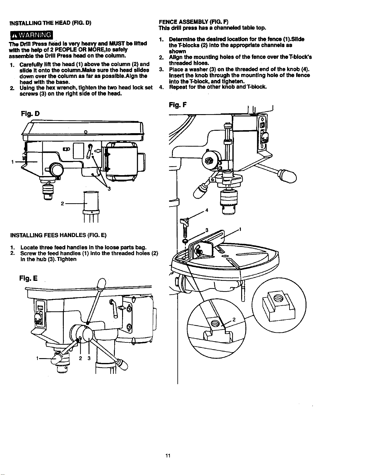
INSTALLING THE HF.AD (FIG. D)
mvl/_d_ql K_
The DrillPress h_d Is very heavy and MUST be lifted
with the help of 2 PEOPLE OR MORE,to safely
assemble the Drill Press head on the column.
1. Carefully lift the head (1) above the column (2) and
slide it ontothe column.Make sure the head slldea
down over the column as far as poealble.Algn the
head with the base.
2. Using the hexwrench, tighten the two head lock eat
screws (3) on the right side ofthe head.
Fig. D
"ry
J
_3
INSTALLING FEES HANDLES(FIG. E)
1. Locate three feed handles in the loose parts bag.
2, Screw the feed handles (1) into the threaded holes (2)
in the hub (3), Tighten
FENCE ASSEMBLY (FIG. F)
This drill press has a channeled table top.
1. Determine the desired location for the fence (1).Sllde
theT-blocks (2) Into the appropriate channels as
shown
2. Align the mounting holes ofthe fence over theT-block's
threaded hloes.
3. Place a washer (3) on the threaded end of the knob (4).
Insert the knob through the mounting hole of thefence
into theT-block,and Ugbetan.
4. Repeatfor the other knobandT-block.
Fig. F
11
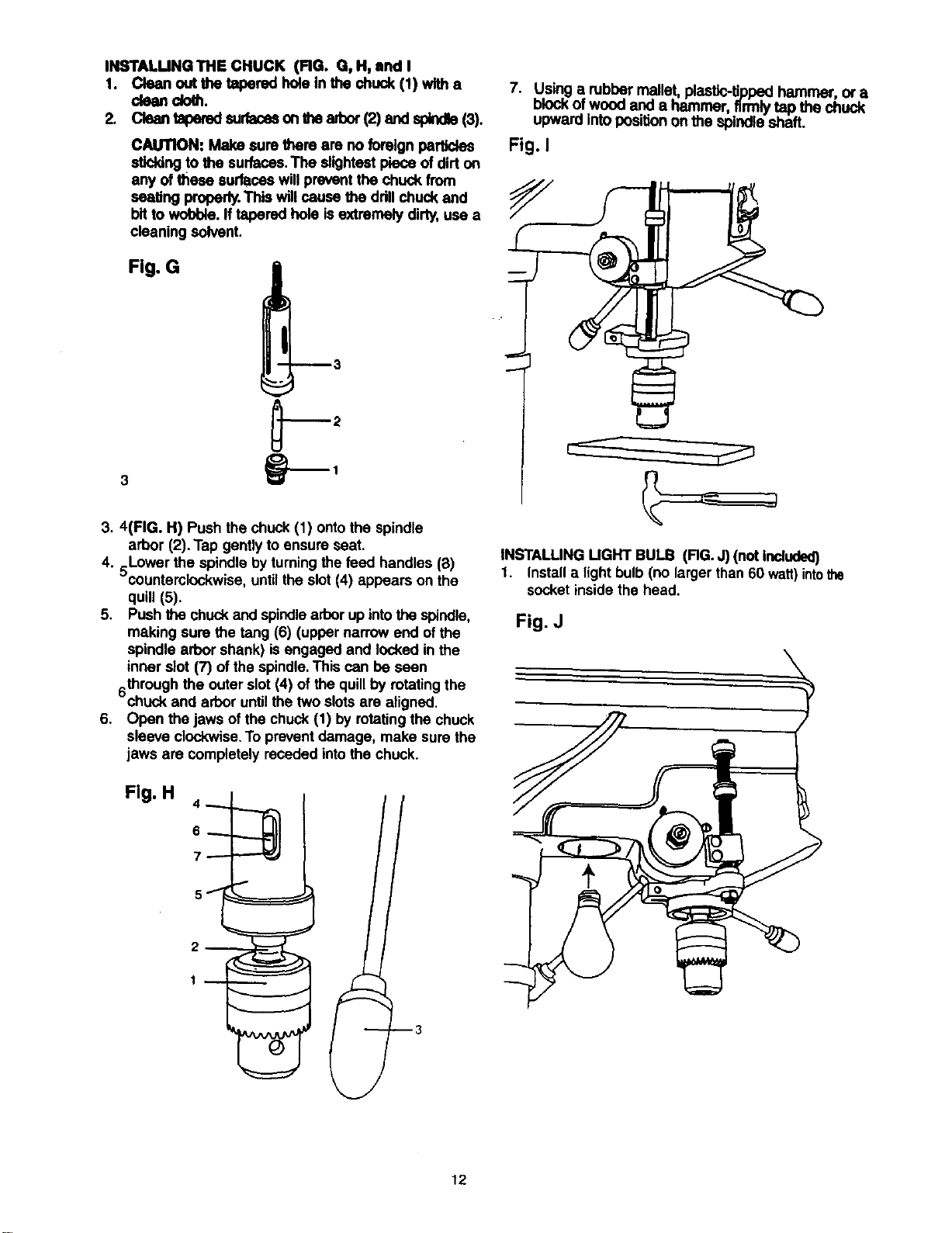
INSTALUNG THE CHUCK (FIG. G, H, and I
1. Clean out the tapered hole In the chuck (1) wltha
CkHlndoth.
2. Clean taperedsurfacasonthe arbor(2) and spindle(3).
CAUTION: Make sure there am no foreignparticles
stk:kingto the surfaces.The slightestpiece ofdirt on
any of these surfaces willprevent the chuck from
seating properly.This willcause the ddll chuck and
bit to wobble. Iftapered hole is extremely dirty, use a
cleaning solvent.
Fig. G
7. Using a robber mallet, plastic-tippedhammer, or a
mOCKOTwood and a hammer, firmlytap the chuck
upward intoposi_n on the spindle shaft.
Fig. I
3. 4(FIG. H) Push the chuck(1) ontothe spindle
arbor (2). Tap gentlyto ensure seat.
4. 5Lower the spindle byturning thefeed handles (8)
countemlockwise, untilthe slot (4) appears on the
quill (5).
5. Push the chuck and spindlearborup intothe spindle,
making sure the tang (6) (upper narrow end of the
spindle arbor shank) is engaged and lockedin the
inner slot (7) of the spindle.This can be seen
throughthe outer slot (4) of the quillby rotatingthe
chuck and arbor untilthe two slotsare aligned.
6. Open the jaws of the chuck (1) by rotatingthe chuck
sleeve clockwise.To preventdamage, make sure the
jaws are completely receded intothe chuck.
Fig. H 4 _. "----,_ I
INSTALLING UGHT BULB (RG. J) (not Included)
1. Installa light bulb(no larger than 60 watt)intothe
socket inside the head.
Fig. J
12
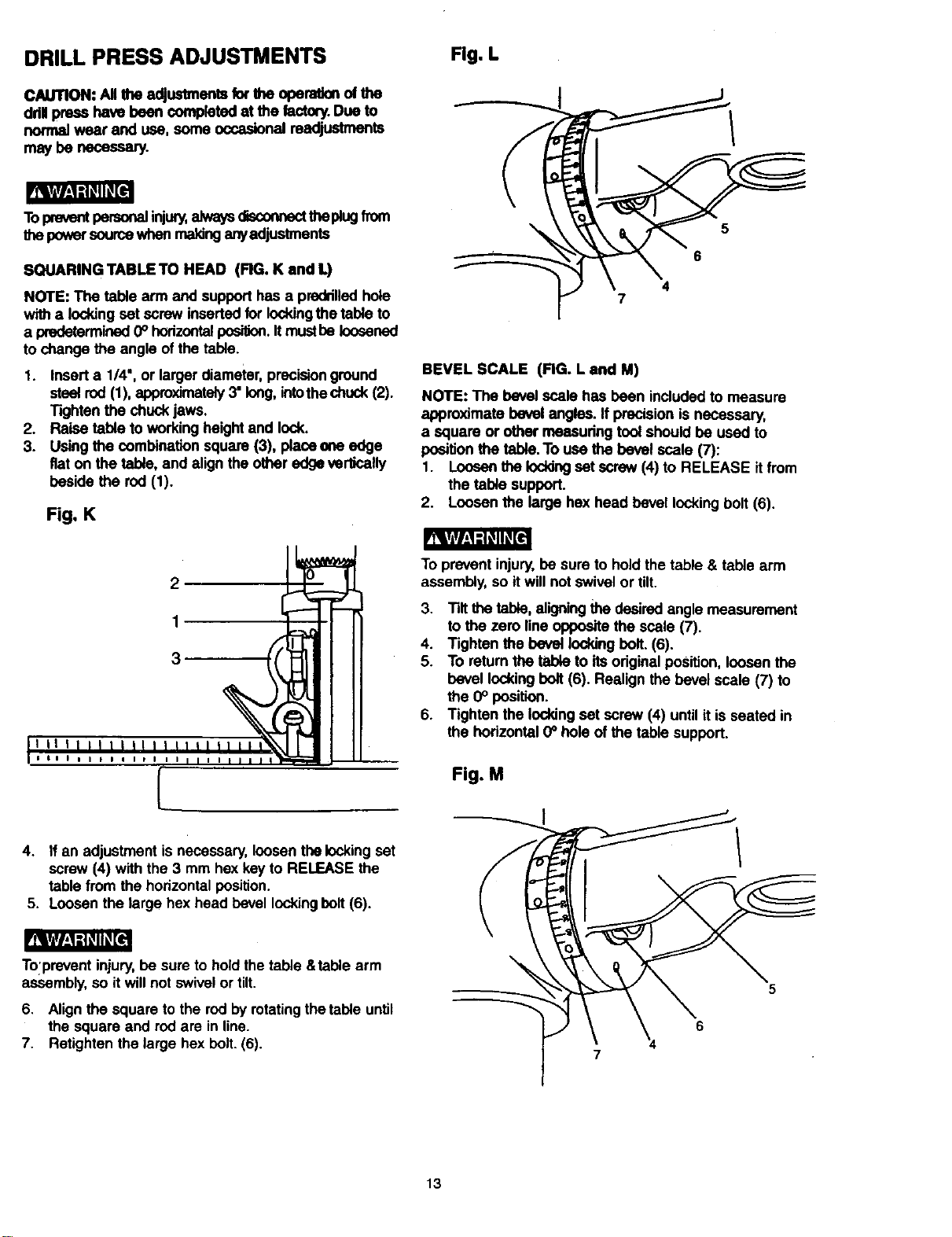
DRILL PRESS ADJUSTMENTS
CAUTION: All the adjustments for the opera,on of the
ddl press have been completed at the lectory.Due to
normalwear and use, some occasionalmadjustmente
may be necessary.
!_W_,I -'l_l_[el
Topreventpersonalinjury,a dysciscor. thepaugfnxn
the powersourcewhen ma;dnganyadjustments
SQUARING TABLE TO HEAD (RG. K and L)
NOTE: The table arm and supporthas a preddlledhole
witha lockingset screw insertedfor lockingthe table to
a predetermined0° horizontal_. Itmustbe loosened
to change the angle of the table.
1. Insert a 1/4", or larger diameter,precisionground
stsetrod(1), approximately3" long,intothechuck(2).
Tighten the chuckjaws.
2. Raise table to workingheightand lock.
3. Usingthe combinationsquare (3), placeena edge
fiat on the tebie, and alignthe other edge verlfoally
beside the rod (1).
Fig. K
Fig. L
5
6
4
7
BEVEL SCALE (FIG. L and M)
NOTE: The bevel scale has been included to measure
approximate bevel angles. If precision is necessary,
a square or othermeasuring toolshould he used to
positionthe table.To use the bevel scale (7):
1. Loosenthe Ioddngset screw (4) to RELEASE itfrom
the table support.
2. Loosen the large hex head bevel lockingbolt(6).
2
1
3
I I I I I I I I I I I I
[
4. If an adjustment is necessary,loosen thelockingset
screw (4) with the 3 mm hex key to RELEASE the
table from the horizontal position.
5. Loosen the large hex head bevel lockingbolt(6).
Tolprevent injury,be sure to hold the table &table arm
assembly,so it willnot swivelor tilt.
6. Alignthe square to the red byrotating the table until
the square and rodare in line.
7. Retightenthe large bex belt. (6).
To prevent injury,be sure to holdthe table & table arm
assembly,so it willnot swivel or tilt.
3. Tilt the table,aligningthedesired angle measurement
to the zero line oppositethe scale (7).
4. Tighten the bevel lockingbolt. (6).
5. To returnthe table to itsoriginalposition,loosen the
bevel lockingbolt (6). Realignthe bevel scale (7) to
the 0° position.
6. Tighten the lockingset screw(4) untilit is seated in
the horizontal 0_hole of the table support.
Fig. M
5
6
7
13
_[wr_,1=t_'llKl[e_
To prevent personalinjury,always disconnect plug
from the power sourcewhen making any adjustment.
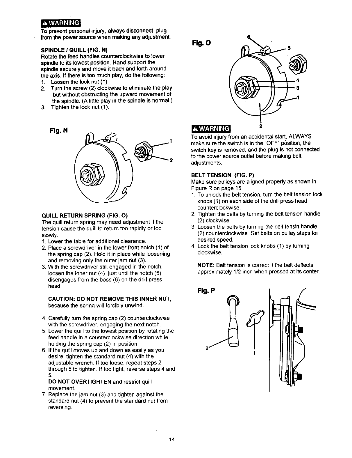
SPINDLE I QUILL (FIG. N)
Rotate the feed handles counterclockwiseto lower
spindleto its lowestposition.Hand supportthe
spindlesecurely and move itback and fortharound
the axis. If there is too much play,do the following:
1. Loosenthe lock nut(1).
2. Turn the screw (2) clockwiseto eliminate the play,
butwithoutobstructingthe upward movement of
the spindle. (A littleplay in the spindleisnormal.)
3. Tighten the lock nut(1).
Fig. O
Fig. N
QUILL RETURN SPRING (FIG. O)
The quillreturnspring may need adjustment ifthe
tensioncause the quillto returntoo rapidly or too
slowly.
1. Lowerthe table for additionalclearance.
2. Placea screwdriverin the lower front notch(1) of
the springcap (2). Hold it in place while loosening
and removingonlythe outerjam nut (3).
3. With the screwdriverstillengaged inthe notch,
loosenthe inner nut(4) just untilthe notch(5)
disengagesfrom the boss (6) on thedrillpress
head.
CAUTION: DO NOT REMOVE THIS INNER NUT,
because the springwill forcibly unwind.
4. Carefully turn the spring cap (2) counterclockwise
with the screwdriver, engaging the next notch.
5. Lower the quill to the lowest position by rotating the
feed handle in a counterclockwise direction while
holding the spring cap (2) in position.
6. If the quill moves up and down as easily as you
desire, tighten the standard nut (4) with the
adjustable wrench. If too loose, repeat steps 2
through 5 to tighten. If too tight, reverse steps 4 and
5.
DO NOT OVERTIGHTEN and restrict quill
movement.
7. Replace the jam nut (3) and tighten against the
standard nut (4) to prevent the standard nut from
reversing.
2
To avoidinjury from an accidental start, ALWAYS
make sure the switch is in the "OFF" position, the
switch key is removed, and the plug is not connected
to the power source outlet before making belt
adjustments.
BELT TENSION (FIG. P)
Make sure pulleysare alignedproperly as shown in
FigureR on page 15.
1. To unlockthe belt tension,turnthe belt tensionlock
knobs (1) on each side of the drillpresshead
counterclockwise.
2. Tightenthe belts by turningthe belt tension handle
(2) clockwise.
3. Loosenthe beltsby turning the belt tensinhandle
(2) counterclockwise.Set belts on pulleystepsfor
desired speed.
4. Lockthe belt tensionlockknobs(1) byturning
clockwise.
NOTE: Belt tension is correct ifthe belt deflects
approximately 1/2 inch when pressed at itscenter.
Fig. P
14
_vlvh_=1_[I
To avoid injury from an accidental start, ALWAYS
make sure the switch is in the "OFF" position, the
switch key is removed, and the plug is not connected
to the power source outlet before making belt
adjustments.
ALIGNING THE BELT PULLEYS (FIG. N)
Open the head cover of the Drill Press. Check
alignment of the pulleys with a straight edge (5) such
as a framimg square, a level, or a piece of a wood.
Lay the straight edge across the top of the pulleys. If
all three pulleys are NOT aligned:
1. Release belt pressure by loosening the belt tension
lock knobs (4) on either side of the head, unlocking
the belt tension handle (1).
2. Loosen the motor mount nuts (2). Lift or lower the
motor (3) until the pulleys are in line.
3. Tighten the motor mount nuts (2) using an
adjustable wrench.
NOTE: To avoid rattles or other noise, the motor
housing should not touch the lower belt guard
housing.
4. Retighten the belts by turning the belt tension
handle (1) clockwise, until the belt deflects
approximately 1/2 inch when pressed in the center.
NOTE: Refer to the chart inside the belt guard
cover for recommended drilling speeds and
belt/pulley positions.
5. Lock the belt tension lock knobs (4) by turning
clockwise.
NOTE: When the belts are new, it may be difficult to
move the belts. As the machine is used, the belts will
gain more elasticity and will be easier to adjust.
Fig. Q
BASIC DRILL PRESS OPEATIONS
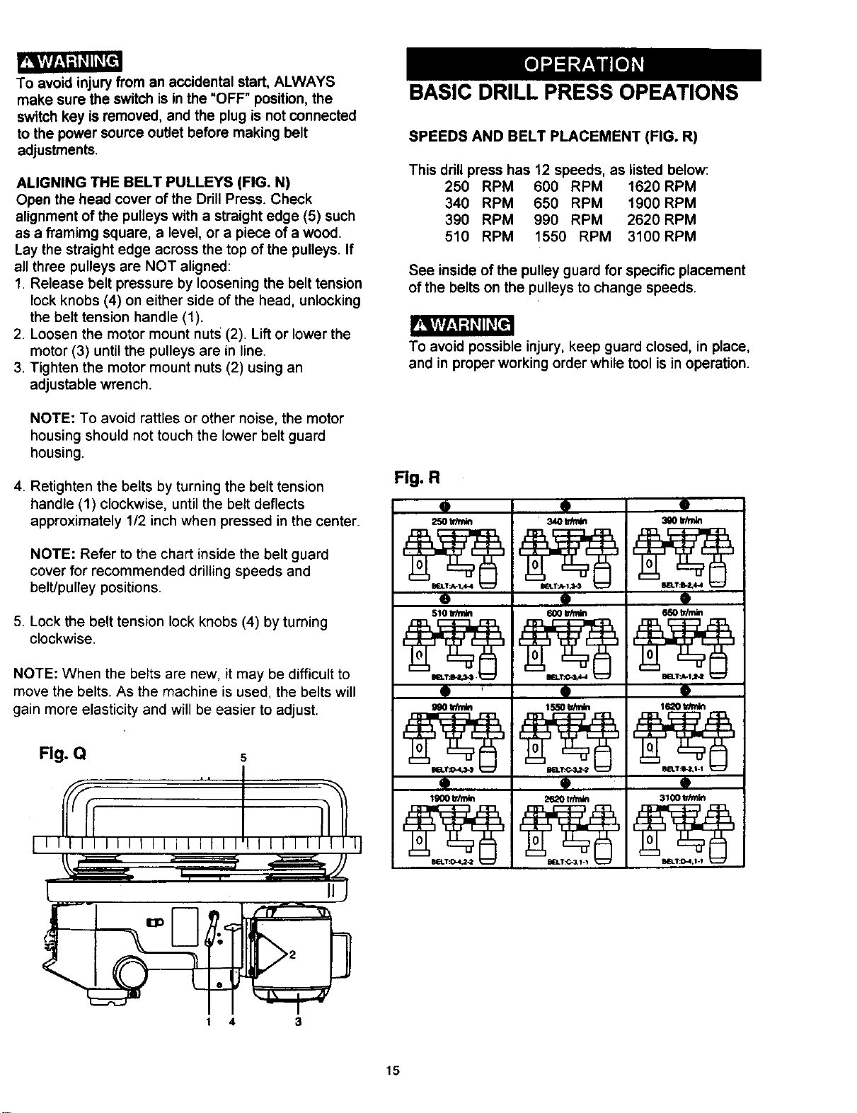
SPEEDS AND BELT PLACEMENT (FIG. R)
This drill press has 12 speeds, as listed below:
250 RPM 600 RPM 1620RPM
340 RPM 650 RPM 1900RPM
390 RPM 990 RPM 2620 RPM
510 RPM 1550 RPM 3100RPM
See inside of the pulley guard for specific placement
of the belts on the pulleys to change speeds.
To avoid possible injury, keep guard closed, in place,
and in proper working order while tool is in operation.
Fig. R
9
250 trim_
o
510 tdmin
i
9
9
9
9
9
9
Q
9
9
3100 tr_lin
1 4 3
15
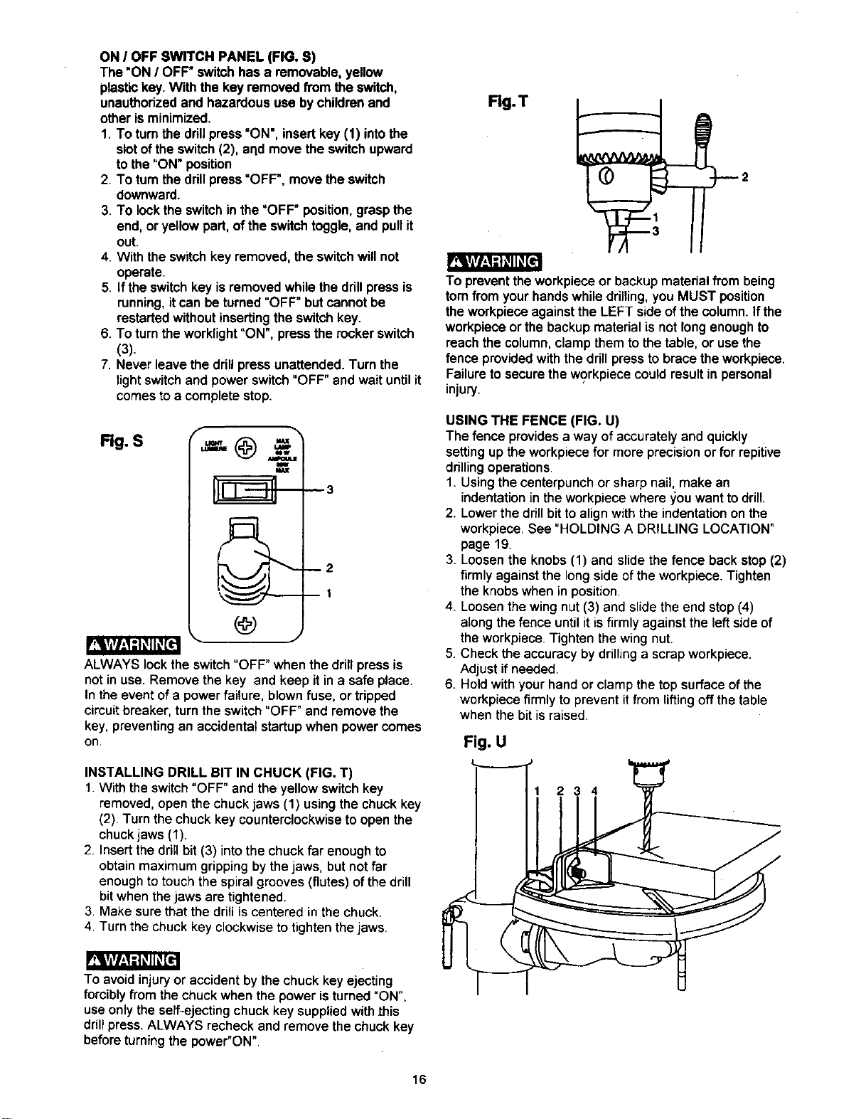
ON I OFF SWITCH PANEL (FIG. S)
The "ON I OFF" switchhas a removable, yellow
plastickey.With the key removed from the switch,
unauthorizedand hazardous use bychildrenand
otheris minimized.
1. To turnthe drillpress "ON', insertkey (1) intothe
slotof theswitch(2), aqd movethe switchupward
to the"ON" position
2. To turnthedrillpress"OFF', movethe switch
downward.
3. To lockthe switchinthe =OFF"position, graspthe
end,or yellowpart,of the switchtoggle, and pullit
out.
4. Withthe switchkey removed, theswitchwillnot
operate.
5. If theswitchkey is removedwhilethe drillpress is
running,itcan beturned "OFF"butcannotbe
restartedwithoutinsertingthe switchkey.
6. To turnthe worklight"ON", pressthe rockerswitch
(3).
7. Never leavethe drillpressunattended. Turn the
lightswitchand powerswitch"OFF" and waituntilit
comesto a completestop.
Rg. S
f
m
_3
--2
BI
ALWAYS lock theswitch"OFF" when the drill press is
not in use. Remove the key and keep it in a safe place.
In the event of a power failure, blown fuse, or tripped
circuit breaker, turn the switch "OFF" and remove the
key, preventing an accidental startup when power comes
on.
INSTALLING DRILL BIT IN CHUCK (FIG. T)
1.With theswitch"OFF"and the yellow switchkey
removed, openthe chuckjaws (1) usingthe chuckkey
(2). Turn thechuck key counterclockwiseto openthe
chuckjaws (1).
2. Insertthe drillbit (3) into the chuck far enoughto
obtainmaximum grippingbythejaws, butnot far
enoughtotouchthe spiralgrooves(flutes) ofthedrill
bitwhenthe jaws are tightened.
3. Make surethat the drillis centered inthe chuck.
4. Turn the chuckkey clockwiseto tightenthejaws.
To avoidinjury or accident by the chuckkey ejecting
forcibly from the chuck when the power is turned "ON",
use only the self-ejecting chuck key supplied with this
drill press.ALWAYS recheck and remove the chuck key
before turning the power"ON".
Fig.T
To preventthe workpieceor backup materialfrom being
tom from your hands while drilling, you MUST position
the workpiece against the LEFT side of the column. If the
workpiece or the backup material is not long enough to
reach the column, clamp them to the table, or use the
fence provided with the drill press to brace the workpiece.
Failure to secure the workpiece could result in personal
injury.
USING THE FENCE (FIG. U)
The fence provides a way of accuratelyand quickly
settingup the workpiecefor more precisionorfor repitive
drillingoperations.
1. Usingthecenterpunchor sharpnail, make an
indentationin the workpiecewhere _ou wantto drill.
2. Lowerthe drillbit toalignwith the indentationon the
workpiece.See "HOLDING A DRILLING LOCATION"
page 19.
3. Loosenthe knobs(1) and slidethe fence backstop (2)
firmly againstthe longside ofthe workpiece.Tighten
the knobswhen inposition.
4_ Loosenthe wingnut (3) and slidethe end stop(4)
alongthe fence untilitisfirmly againstthe leftsideof
the workpiece.Tightenthe wing nut.
5. Check the accuracybydrillinga scrapworkpiece.
Adjust ifneeded.
6. Holdwithyourhandor clamp thetop surface ofthe
workpiecefirmly toprevent it from liftingoff thetable
when the bit is raised.
Fig. U
234
16
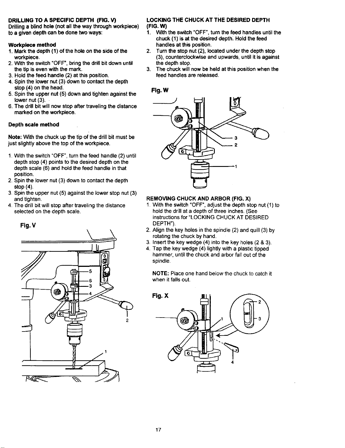
DRILLING TO A SPECIFIC DEPTH (FIG. V)
Drillinga blindhole (not all the way throughworkpiece)
toa givendepthcan be done twoways:
Workpleca method
1. Mark the depth(1) ofthe holeon the side ofthe
workpiece.
2. W'_ththe switch"OFF", bringthe drillbitdownuntil
thetip iseven with themark.
3. Hold thefeed handle (2) at thisposition.
4. Spinthe lowernut (3) downtocontactthe depth
stop(4) on the head.
5. Spinthe upper nut(5) down and tightenagainstthe
lower nut (3)..
6. The drillbitwill nowstopafter travelingthe distance
marked on theworkpiece.
Depth scale method
Note: With the chuckup the tipof'the drillbit mustbe
just slightlyabove thetop of theworkpiece.
1.With theswitch"OFF", turn the feed handle (2) until
depth stop (4) points to the desired depth on the
depth scale (6) and hold the feed handle in that
position.
2. Spin the lower nut (3) down to contact the depth
stop (4).
3. Spin the upper nut (5) against the lower stop nut (3)
and tighten.
4. The drill bit will stop after traveling the distance
selected on the depth scale.
Fig. V
LOCKING THE CHUCK AT THE DESIRED DEPTH
(FIG. W)
1. Withthe switch"OFF",turnthe feed handlesuntilthe
chuck (1) isat the desireddepth_Hold the feed
handlesat this position.
2. Turn the stopnut (2), located underthe depthstop
(3), counterclockwiseand upwards,untilitisagainst
the depthstop.
3. The chuckwillnow be heldat this positionwhen the
feed handlesare released.
Flg.W
REMOVING CHUCK AND ARBOR (FIG. X)
1. With the switch"OFF", adjust thedepth stopnut(1) to
holdthedrillat a depthofthree inches. (See
instructionsfor "LOCKING CHUCK AT DESIRED
DEPTH").
2. Align the key holesinthe spindle(2) and quill(3) by
rotatingthe chuckbyhand.
3. Insertthe key wedge (4) into the key holes(2 & 3).
4. Tap the key wedge (4) lightlywith a plastictipped
hammer, until the chuckand arborfall out ofthe
spindle.
NOTE: Place one hand below the chuck to catch it
when it falls out.
Fig. X
S
4
17
BASIC OPERATION INSTRUCTIONS
To getthe bestresultsand minimizethe likelihoodof
personalinjury,follow these instructionsfor operating
yourdrillpress.
Foryourownsafety, always observethe SAFETY
INSTRUCTIONS listedhere and on pages 3, 4 and 5
ofthe instructionmanual.
YOUR PROTECTION
To avoidbeing pulledintothe powertool,do notwear
looseclothing,gloves,neckties,orjewelry. Always tie
backlonghair.
1. If any part ofyour drill press is missing, malfunctioning,
damaged or broken, stopoperation immediatelyuntil
that partis properlyrepairedor replaced.
2. Never placeyourfingers in a positionwhere they
couldcontactthe drillbitor othercuttingtool. The
workpiecemay unexpectedlyshift,or your handcould
slip.
3. To avoidinjuryfrom partsthrownbythe spring,follow
instructionsexactlywhen adjustingthe springtension
of thequill.
4. To preventheworkpiecefrom being tornfrom your
hands,thrown,spunby the tool,or shattered, always
properlysupportyourworkpiece as follow:
a. Always positionBACKUP MATERIAL (used
beneathworkpiece) sothat itcontactsthe left
sideofthe column,or use the fence providedand
a clamp to brace a small workpiece.
b. Whenever possible,positiontheWORKPIECE to
contactthe leftside ofthe column. Ifit istoo short
or thetable istilted, usethe fence providedor
clampsolidlyto the table, usingthe table slots.
c. When usinga drillpressvise, always fasten itto
thetable.
d. Never do anywork freehand (hand-holdingthe
workpieceratherthan supportingiton the table),
exceptwhen polishing.
e. Securelylockthe head and supporttothe column,
thetable arm tothe support,and the table tothe
tablearm, beforeoperatingthe drillpress.
f. Never movethe head or the table while thetool is
running.
g. Beforestartingan operation,jog the motorswitch
tomake sure the drillor othercuttingtooldoes not
wobble orcause vibration.
h. Ifa workpieceoverhangsthe table so itwillfall or
tip ifnot held,clamp ittothe table or provide
auxiliarysupport.
i. Use fixturesfor unusualoperationsto adequately
hold,guide,and positionworkpiece.
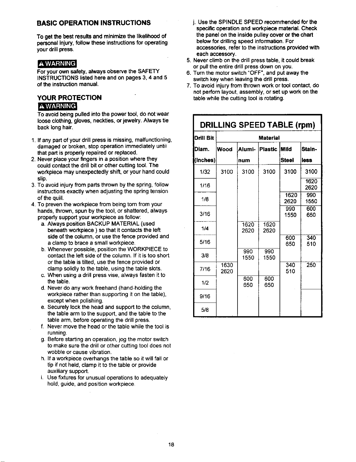
j. Use the SPINDLE SPEED recommended for the
specificoperation and workpiecematerial. Check
the panel on the insidepulleycover or the chart
belowfor drillingspeed information.For
accessories,refer tothe instructionsprovidedwith
eachaccessory.
5. Never climbon the drillpresstable, it couldbreak
or pullthe entiredrillpressdownon you.
6. Turn the motorswitch"OFF", and putaway the
switchkey when leaving the drillpress.
7. To avoidinjuryfrom thrownwork or toolcontact,do
notperfornlayout, assembly,or set up work on the
table whilethe cuttingtool isrotating.
DRILLING SPEED TABLE (rpm)
Drill Bit Material
Diam. Wood 6.1umi- Plastic Mild Stain-
(Inches) mum Steel less
1/32 3100 3100 3100 3100 3100
1620
1/16 2620
1620 990
1/8 2620 1550
990 600
3/16 1550 650
1620 1620
1/4 2620 2620
600 340
5/16 650 510
990 990
3/8 1550 1550
1630 340 250
7/16 2620 510
600 600
1/2 650 650
9/16
5/8
18
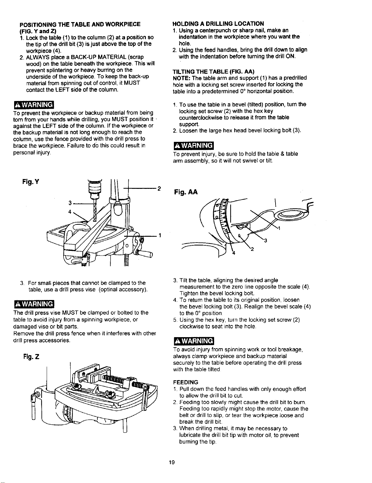
POSITIONING THE TABLE AND WORKPIECE
(FIG. Y and Z)
1. Lockthetable (1) to thecolumn(2) at a positionso
thetipofthe drillbit (3) is just abovethe topofthe
workpiece(4).
2. ALWAYS place a BACK-UP MATERIAL (scrap
wood)on the table beneaththe workpiece.Thiswill
preventsplinteringor heavyburringon the
undersideof theworkpiece. To keep the back-up
material from spinning out of control, it MUST
contact the LEFT side of the column.
To prevent the workpiece or backup material from being
torn from your hands while drilling, you MUST position it
against the LEFT side of the column. If the workpiece or
the backup matedal is not long enough to reach the
column, use the fence provided with the drill press to
brace the workpiece. Failure to do this could result in
personal injury.
HOLDING A DRILLING LOCATION
1. Usinga centerpunchor sharpnail,make an
indentationintheworkpiecewhereyouwantthe
hole.
2. Usingthefeed handles,bdng thedrilldowntoalign
withthe indentationbeforeturningthedrillON.
TILTING THE TABLE (FIG. AA)
NOTE: The table arm and support (1) has a preddlled
hole with a locking set screw inserted for locking the
table into a predetermined 0 ° horizontal position.
1. To use the table in a bevel (tilted) position, turn the
locking set screw (2) with the hex key
counterclockwise to release it from the table
support.
2. Loosen the large hex head bevel locking bolt (3).
_t
To prevent injury,be sure to hold the table& table
arm assembly, so it will not swivel or tilt.
Fig. Y
2
Fig. AA
\
3. For small pieces that cannot be clamped to the
table, use a drill press vise (optinal accessory).
The drill press vise MUST be clamped or bolted to the
table to avoid injury from a spinning workpiece, or
damaged vise or bit parts.
Remove the drill press fence when it interferes with other
drill press accessories.
Fig. Z
3. Tilt the table, aligning the desired angle
measurement to the zero line opposite the scale (4).
Tighten the bevel locking bolt.
4 To return the table to its original position, loosen
the bevel locking bolt (3). Realign the bevel scale (4)
to the 0° position
5 Using the hex key, turn the locking set screw (2)
clockwise to seat into the hole.
To avoid injury from spinning work or tool breakage,
always clamp workpiece and backup material
securely to the table before operating the drill press
with the table tilted
FEEDING
1. Pull down the feed handles with only enough effort
to allow the drill bit to cut.
2 Feeding too slowly might cause the drill bit to burn.
Feeding too rapidly might stop the motor, cause the
belt or drill to slip, or tear the workpiece loose and
break the drill bit
3. When drilling metal, it may be necessary to
lubricate the drill bit tip with motor oil, to prevent
burning the tip.
19

MAINTAINING YOUR DRILL PRESS
Foryourownsafety, turnthe switch=OFF"and remove
theplugfrom the powersourceoutletbeforemaintaining
or lubricatingyourdrillpress.
Frequentlyblow out, usingan air compressoror dust
vacuum,anydustthat accumulatesinsidethe motor.
A coatofautomotivepastewax appliedto thetable and
columnwillhelpto keep the surfaceclean.
To avoidshock or fire hazard, ifthe powercordiswornor
cutin anyway, have itreplaced immediately.
LUBRICATION
Allofthe drillpressball bearingsare packedwith grease
at the factory. They requireno further lubrication.
Periodicallylubricatethe gear and rack, table elevation
mechanismofthe spindlethe rack(teeth) ofthequill.
20
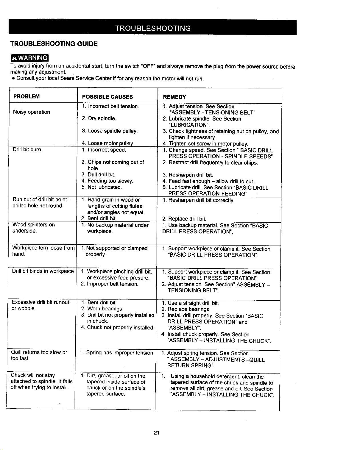
TROUBLESHOOTING GUIDE
To avoidinjuryfrom an accidentalstart,turnthe switch"OFF" and always removethe plugfrom thepowersourcebefore
makinganyadjustment.
• ConsultyourlocalSears Service Center iffor any reasonthemotorwillnotrun.
PROBLEM
Noisyoperation
Drill bit burn.
Runoutof drill bit point -
drilled holenot round.
Wood splinters on
underside.
Workpiece torn loose from
hand.
Drill bit binds inworkpiece.
Excessive drill bit runout
orwobble.
Quill returns too slow or
too fast.
Chuck will not stay
attached to spindle. It falls
off when trying to install.
POSSIBLE CAUSES
1. Incorrectbelttension.
2. Dry spindle.
3. Loose spindlepulley.
4. Loosemotor pulley.
1. Incorrect speed.
2. Chips notcomingout of
hole.
3. Dull drill bit.
4. Feeding too slowly.
5. Not lubricated.
1. Hand grain in wood or
lengths of cutting flutes
and/or angles not equal.
2. Bent drill bit.
1. No backup material under
workpiece.
1.Not supported or clamped
properly.
1. Workpiece pinching drill bit,
or excessive feed presure.
2. Improper belt tension.
1. Bent drill bit.
2. Worn bearings.
3. Drill bit not propedy installed
in chuck.
4. Chuck not properly installed.
1. Spring has improper tension.
1. Dirt, grease, or oil on the
tapered inside surface of
chuck or on the spindle's
tapered surface.
REMEDY
1. Adjust tension. See Section
"ASSEMBLY - TENSIONING BELT"
2. Lubricate spindle.See Section
"LUBRICATION".
3. Check tightness of retaining nut on pulley, and
tighten if necessary.
4. Tighten set screw in motor pulley.
1. Change speed. See Section" BASIC DRILL
PRESS OPERATION - SPINDLE SPEEDS"
2. Restract drill frequently to clear chips.
3. Resharpen drill bit.
4. Feed fast enough - allow drill to cut.
5. Lubricate drill. See Section "BASIC DRILL
PRESS OPERATION-FEEDING"
1. Resharpen drill bit correctly.
2. Replace drill bit.
1. Use backup material. See Section "BASIC
DRILL PRESS OPERATION".
1. Support workpiece or clamp it. See Section
"BASIC DRILL PRESS OPERATION".
1. Support workpiece or clamp it. See Section
"BASIC DRILL PRESS OPERATION".
2. Adjust tension. See Section" ASSEMBLY -
TENSIONING BELT".
1. Use a straight drill bit.
2. Replace bearings.
3. Install drill properly. See Section "BASIC
DRILL PRESS OPERATION" and
"ASSEMBLY".
4. Install chuck properly. See Section
"ASSEMBLY - iNSTALLING THE CHUCK".
1. Adjust spring tension. See Section
"ASSEMBLY - ADJUSTMENTS -QUILL
RETURN SPRING".
1. Using a household detergent, clean the
tapered surface of the chuck and spindle to
remove all dirt, grease and oil. See Section
"ASSEMBLY - INSTALLING THE CHUCK".
21
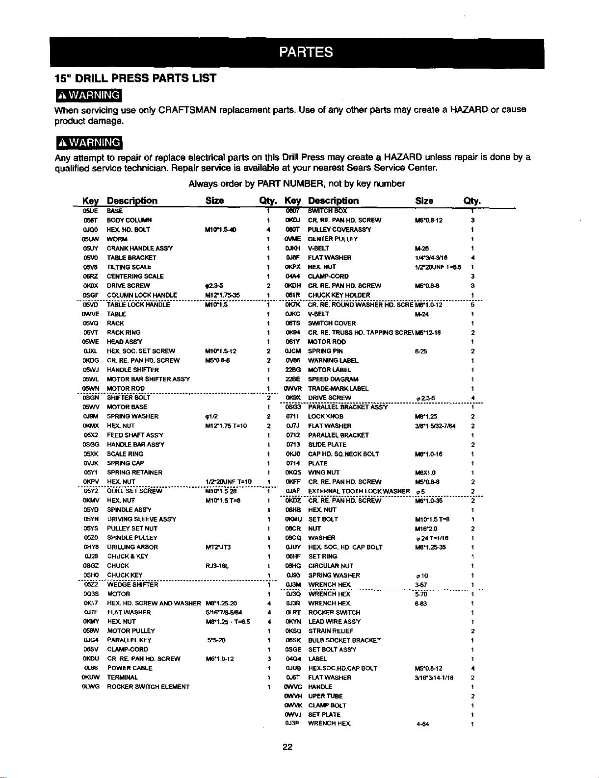
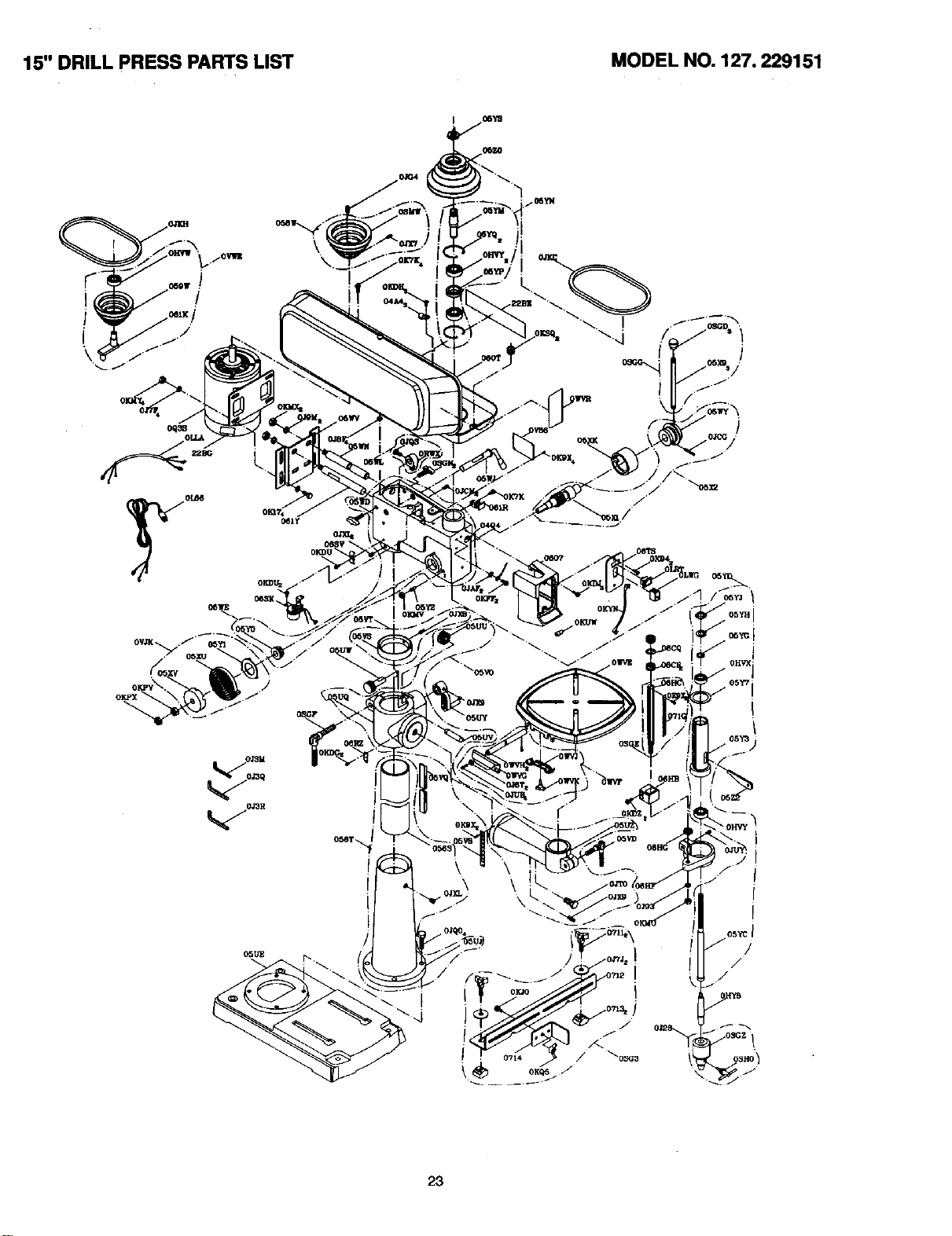
15" DRILL PRESS PARTS LIST
When servicinguse onlyCRAFTSMAN replacement parts•Use ofany other parts may create a HAZARD or cause
productdamage,
Any attemptto repairot replace electricalparts on this Ddll Press may create a HAZARD unlessrepair isdone by a
qualifiedservice technician.Repair service is availableat yournearest Sears Service Center•
Alwaysorder by PARTNUMBER, not by key number
Size Qty. Key Description
M10"1.5_I0
0e07
0e0T
0VME
OJKH
0JBF
0t_oX
04A4
_.5-5 0KDH
Key Descdpfon
0SUE BASE
0583" BODY COLUMN
0JQO HEX. HD, BOLT
05UW WORM
05UY CRANKHANDLE ASS'Y
05VO TABLEBRACKET
05V8 TILTING SCALE
06RZ CENTERING SCALE
0KgX ORIVE SCREW
(_GF COLUMN LOCKHANDLE
Size Qty.
SWITCH BOX 1
CR. RE. PAN HD. SCREW M5"0.8-12 3
PULLEY COVERASS'Y I
CENTER PULLEY 1
V-BELT I_28 I
FLATWASHER 114"3/4_/16 4
HEX. NUT 1FJ'20UNFT==6.5 1
CLAMP-CORD 3
CR. RE. PAN HD. SCREW M6"0.8-8 3
1Mt 2"1.75-35 061R CHUCK KEy HOLDER
05VD TABLE LOCK HANDLE MtO*I_S OK7K CR_ BE_ ROUND WASHES HO_ SCBE MI8"1_0.12 5
0WVE TABLE
(]SVQ RACK
0b_rF RACK RING
(]SWE HEADASS'Y
0JXL HF.._SOC. SET SCREEN M10"I .5-12
0KDG CB RE. PAN HD. SCREW M5"0.8-6
05hVJ HANDLE SHIFTER
05WL MOTOR BAR SHIFTER ASS'Y
05WN MOTOR ROD
OSGN BH3FTERBOLT
05WV MOTOR BASE
OJgM SPBINGWASHER _112
HEX.NUT M12*1_75T=|0
05X2 FEED SHAFT ASS_F
OSGG HANDLE BARABS'Y
05XK SCALERING
OVJK BPR_NGCAP
05YI SPRING RETA_NEB
OKPV HF.X.NUT II2*20UNF T=IS
05Y2 OUILL SET SCREW M10"1_5-28
SKMV HEX_NUT M16*1_ST=8
05YD SP_NBLEABS'Y
05YN DRMNG SLEEVE ASS'Y
05YS PULLEYBET NUT
05Z0 SP_NBLEPULLEY
OHY8 DRILUNG ARBOR MT2*JT3
0J28 CHUCKS KEY
OSGZ CHUCK RJ3-16L
OSHO CHUCK KEY
05Z2 WEDGE BHIFTER
OQ3S MOTOR
0K17 HEX_HD_SCRE_NAND WASHER M8"I__S-20
OJ7F FLAT WASHER 5J16"715-5i64
OfO_Y HEY..NUT M6.1_5 •T=6_5
058W MOTOR PULLEy
OJG4 PARALLEL KEy 5*5-20
06SV CLAMPJCORD
OKDU CR RB_PAN HD_SCREW M6"I_0-12
0L66 POWER CASLE
OKUW TERMINAL
OLWG ROCKER BWiTCH ELEMENT
0JKC V-BELT kk24 1
06TB SWITCH COVER 1
01<94 CR. RE. TRUSS HO. TAPPING SCRE_ M5"12-16 2
061Y MOTOR ROO 1
0JCM SPRING PIN 6-25 2
0V86 WARNING LABEL 1
22BG MOTOR LABEL 1
228E SPEED DIAGRAM 1
GWVR TRADEJA_RK LABEL 1
0_gX DRIVE SCREW _ Z3-5 4
0SG3 PARALLEL _=P,ACKET ASS"{ 1
O711 LOCK KNOB M8"1.25 2
0JTJ FLATWASHER 3/8"1_32-7,_4 2
0712 PARALLELBRACKET 1
0713 SLIDE PLATE 2
0KJO CAP HD, $QNECK BOLT M6"t,0-16 1
0714 PLATE 1
0KQ5 WING NUT M6Xl.0 1
01_F CR. RE. PAN HD. SCREW M5"0._8 2
01AF EXTERNALTOOTHLOCKWASHER _5 2
OKDZ CR_ RE_ PAN HD_ SCREW M6"1 _0-35 2
06HB HEX. NUT 1
0t_MU SET BOLT M10"1.5 T-_B 1
06CR NUT M16"2.0 2
_6CQ WASHER rp24 T=1/16 1
0JUY HEX. SOC, HD, CAP BOLT M_'1.25_5 1
06HF SET RING 1
IToHG CIRCULAR NUT 1
0J93 SPRtNG WASHER _10 1
OJ3M WRENCH HEY-. 3_57 1
0J3Q WRENCH HEX. 5-70 1
0J3R WRENCH HEX. 6-83 1
0LRT ROCKER SWITCH 1
0KYN LEADWIRE ASS'Y 1
0KSQ STRAIN REUEF 2
06SK BULB SOCKET BRACKET 1
G_GE SET BOLTASS_ 1
04Q4 LABEL 1
0JUS HEX.SOC,HD.CAP BOLT M5"0,8-12 4
0J6T FLATWASHER 3/16"3/14-1/16 2
0WVG HANDLE 1
0WVH UPER TUBE 2
0WVK CLAMP BOLT 1
0WVJ SET PLATE 1
0J3P WRENCH HEX. 4-64 1
22
15" DRILL PRESS PARTS LIST
MODEL NO. 127. 229151
/
23

24
Manual de Operaci6n
CRIIFTSMllN"
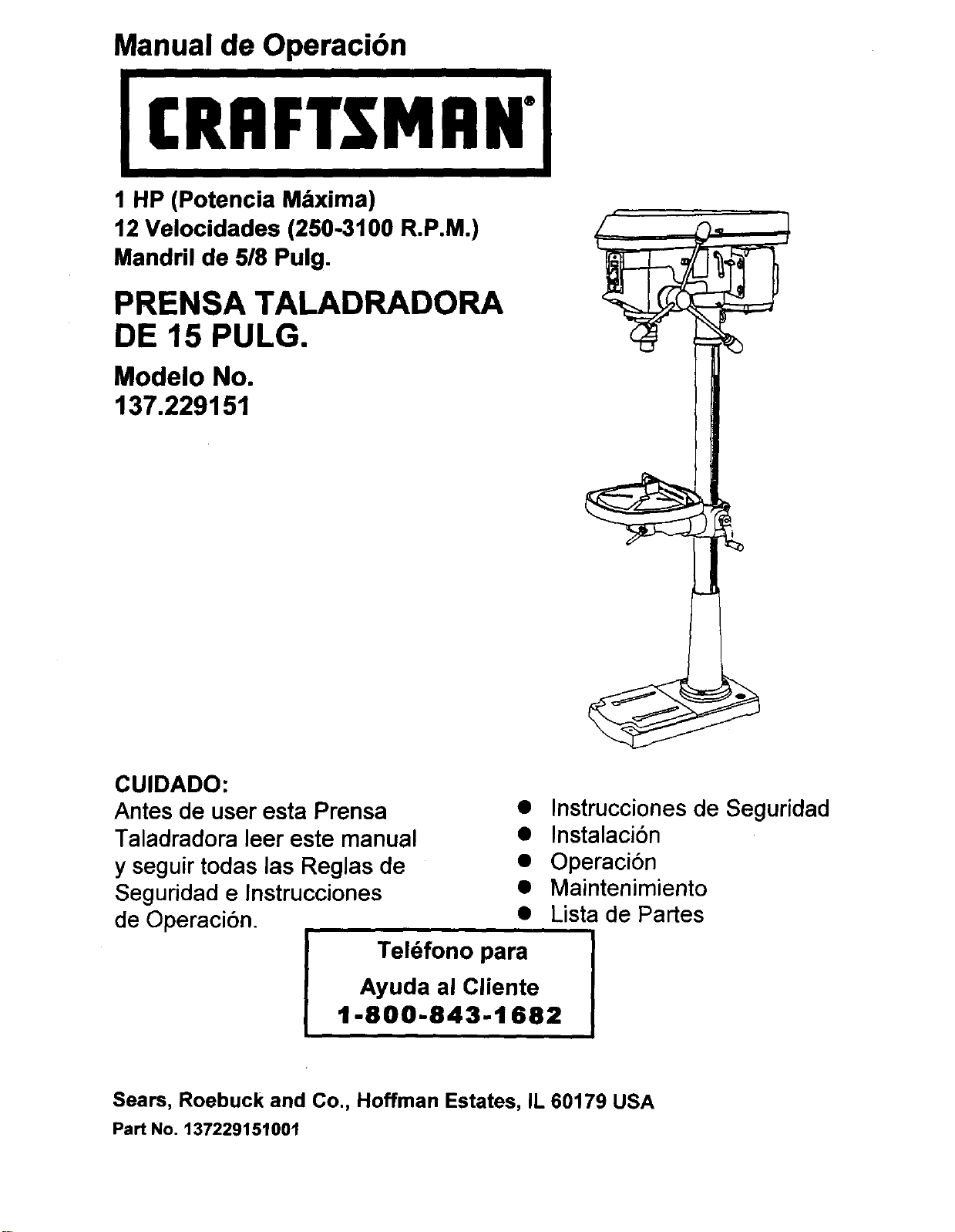
1 HP (Potencia M&xima)
12 Velocidades (250-3100 R.P.M.)
Mandril de 518Pulg.
PRENSA TALADRADORA
DE 15 PULG.
Modelo No.
137.229151
CUIDADO:
Antes de user esta Prensa •
Taladradora leer este manual •
y seguir todas las Reglas de •
Seguridad e Instrucciones •
de Operaci6n. •
Tel6fono para
Instrucciones de Seguridad
Instalaci6n
Operaci6n
Maintenimiento
Lista de Partes
Ayuda al Cliente
1-800-843-1682
Sears, Roebuck and Co., Hoffman Estates, IL 60179 USA
Part No. 137229151001
SECCI6N PAGINA
Garania ................................................................................................................. 26
Especiflcaciones de la Herramienta ................................................... ............................. 26
Instrucciones de Segutidad ....................................................................................... 27
Accosorios y Aditamentos ....................................................................................... 30
Contenido de la Caja ................................................................................................ 30
Farniliarizares con la Prensa Taladradora ................................................................ 32
Glosario de T6rminos ............................................................................................. 33
Ensamblaje y Regulaci6n ........................................................................................ 34
Operaci6n ................................................................................................................ 39
Mantenimiento ............................ _........................................................................... 44
Guia para Diagn6stico de Problemas ......................................................................... 45
Partes ...................................................................................................................... 46
GARANTJA TOTAL DE 1 ANO
Siesta herramienta presentase defectos de material o fabricacibn dentro del primer argoa partir de la fecha de
compra, Sears la reparar_ sin costo alguno
Contactarse con un Centro de Servicio de Sears pare la reparacibn.
Siesta herramienta se usa para fines comerciales o para alquiler, esta garantia se aplica s61o per los primeros 90
a partir de la fecha de compra.
Esta garantia le otorga derechos legaLes espec{ficos y tambi_n podrla usted tener otros derechos que varian de un
estado a otto
Sears, Roebuck and Co., Dept. 8t7 WA, Hoffman Estates, IL 60179
r.,_
Certaines poussieresprovenantd'activit6ssur outils_lectdques, comme ponc..age,sciage, meulage, pelage et d'autres activit_s
relatives a la construction contiennent des produits chimiques connues pour causer cancer, anomalies congenitales ou autres dsques
pour la reproduction. Certains exemples de cosproduits chimiques sont :
• plomb provenant de peintures _ base de plomb ;
• silice cristallisee provenant des bdques et du ciment et d'autresproduits de ma<;onnerie, et
• arsenic et chrome provenant du bois chimiquement traite.
Vos dsques d'6tre expos6 _ces produits vadent selon letemps pass6 &faire ce type de travail. Afin de reduire rexposition & cos
produits chimiques, ilfaut travailler dans un endroit bien a6r6, et porter de I'_quipement de securit6 approuve comme des masques
poussi6re congus sp6cialement pour ]e filtrage de particules microscopiques.
TAMAI;IO DEL MANDRIL..5/8°(16 ram)
VELOCIDADES ............... 12 (250 ~ 3,100 RPM)
MOTOR ......................... 120V, 60 Hz, 8 AMPS
CABALLAJE ...................... 1 HP (Desarrollo Max.)
LUZ INCORPORADA .........60 Wats (Mdximo)
(No incluye el foco)
TAMAI;IO DE LA MESA.....13-1/4"x13-1/4" (33.6 cm x 33.6 cm)
INCLINACION
DE LA MESA...................... 45 ° A LA DERECHA O IZQUIERDA
DESPLAZAMIENTO
DEL EJE.............................. 3-1/8"(8 cm)
CUELLO ............................... 7-1/2"(19 cm)
TAMA_IO DE LA BASE-=....11")(20-3/8" (28 cm x 52 cm)
ALTURA ............................... 63-1/4"(1.61 m)
El polvocreado per el lijado mecanico, aserrado, rectificado,
taladrado y otras actividades empleadas en construcci6n
contiene productos quimicos que se sabe causan cancer,
defectos congenitos u otros daSos al sistema reproductor.
Algunos de estos productos quimicos son :
• plomo proveniente de pinturas a base de plomo
• silicecristalizada de ladnllos y cemento y otros productos de
alba_ileria y,
• arsenico y cromo de madera tratada quimicamente.
Su riesgo de exposicibn aestos productos varia dependiendo
de cuan a menudo usted hace este tipo de trabajo. Para reducir
su exposicibn a estos productos quimicos :trabaje en lugares
bien ventiladosy utilice equipo de seguridad aprobado, tal
como mdscaras contra el polvo especialmente disefladas para
filtrar particulas microscopicas.
INSTRUCCIONES GENERALES DE 14.
SEGURIDAD
ANTES DE USAR LA PRENSATALADRADORA
Laseguridadesunacombinaci6ndesenlidocomdn,mantenerse 15.
alertaysabercomousarlaPrermaTaladradera.
'RETiPJ_I_VI_I_eg
Paraevitarermresquepuedancausarlesionesserias,no
conectareltaladrobasrahaderle|doyentendidoIosiguiente:
1 LEERy famiUarizarsocontodeestemanualde
instrucoionesENTENDERlasapiicaciones,limitacinoesy
riesgasposibles
2 MANTENERLOSPROTECTORESENPOSlCI(_Nyen
buenascondicionesdeoperadbn
3. NOOPERARENAMBIENTIESPELIGROSOS.Nousarla
herramientaenlugaresht_medos,mojadesoe._puestosa la
Iluvia.Mantenereldreadetrabajobieniluminada.
4. NOUSARherramientaseldctricasenla presenciade
Ifquidosogasesinflamables.
5. MANTIENERELAREADETRABAJOUMPIA.Lasdreasy
mesasdetrabajocongestJonadasinv_tana queocurran
accidentes.
6. MANTENERA LOSNIl;lOSALEJADOS.Todoslos
visitantesdebenmantenersea unadistanciaseguradel
_reade trabajo
7. NOFORZARLA HERRAMIENTA.Laherramientahardun
mejortmbajoy rodssegurous_ndolaS61Oenlaformapara
laquefuedisefiada.
8. USARLAHERRAMIENTAADECUADA.Noforzarla
herramientaalhaceruntrabajoparaelcoalnohaside
diseSada.
9 USARROPAADECUADANOusarropasuelta,guantes,
corbatas,anillos,brazaletesnijeyasquepuedanquedar
atrapadosanlaspiezasmoviblesdelaherramientaSe
recomiendausarcalzadoantJmsbalanteUsarprendasde
cabezaparacubrirocontenerelcabetlolargo.
10. USARUNAM/t,SCARAPARALA CARAO PARAPOLVO.
Lostrabajoscontatadroproducenpolvo.
11 DESCONECTARLAS HERRAMIENTASantesdecambiarle
accesoriostalescomo:hojas,brocas,cortadoresy similares
12. REDUCIRELRIESGODEARRANQUESACCIDENTALES.
Cerciorarsequeeiinterruptordeenergiaest_enlaposicibn
=OFF"(Apagado)antesdeenchufarlaherramientaa la
corfienteeldctrica.
13. USAR ACCESORIOS RECOMENDADOS. Consultarcon
el manualdelopemdorpara determinar cualesson los
acoesoriosrecomendados.El usode accesorios
inapropiadospuede ser peligrosoygenemr riesgode
lesionespersonales,
RETIRAR LAS HERRAMIENTAS DE
REGULACI_N. Formarseel tk_oitodeverificarquelas
herramientasy lasIlavesde regulaci6nhayansideretJradas
deltaladroantesdeactivarlo.
NUNCADEJARDESATENDIDAUNAHERRAMIENTA
ELI_CTRICACUANDOESTI_FUNClONANDO.
DESCONECTARLA FUENTEDEENERG|A.Noalejarse
dellugarhastaquelaherramientasehayadetenidopor
compieto.
16. NUNCAPARARSESOBRELA HERRAMIENTA.Pusden
ocurdrlesionesseriassilaherramientasevolteaosise
entraencontactoconeltaladro.
17. NOESTIRARSEM/t,SALLADELALCANCEDEUNO.
MantenerlosdospiesbienapoFadosyelequilibroen
todomomento.
18. DARMANTENIMIENTOCUIDADOSOA LAS
HERRAMIENTAS.Pareunaoperaci6nmejor,mdsseguray
rdpida,mantanerlesherramientasaflladasy limpias.Seguir
lasinstruccionesparalalubricack_ycambiodeaccesorios.
t9. INSPECClONARPAPADETECTARPIEZASDANADAS.
Antesdeusarla herramienta,siempreinspeccionada
cuidadosamenteparecemioraressilosprotectoresuotras
piezasest_ndahadasydeterminarsivaa operar
adecuadamenteenelusoqueselevaa dar.Inspecolonar
sihaypiezasmoviblesdesalineadasoatracadas;partes
rotasorealmontadas,y coalquierotracondici6nquepueda
afectarlaoperaci6ndelaherramienta.Siunprotectoro
cualquierotrapiezaestuvieseda_adadeberepamrse
adesuadamenteoreemp_azarse.
20. ASEGURARSEQUELOSNINOSNOTENGANACCESO
ALTALLERDETRABAJO.Usarcandados,intenuptores
maestrosy quitarlosIlavesdeactivaci_n.
21 NOoperarla herramientabajolainfluenciadedrogas,
alcoholomedicamentosquepudiesenafectarlahabilidad
paraoperarlaherramientaadecuadamente
22.
Elpolvogeneradoporciertosmaterialespuedesernocivo
parala salud.SiempreoperarlaPrensaTaladmdoraenun
areabienventiladaparaeliminarelpolvo.Cuandofuese
posible,usarsisternasrecolectoresdepotvo.
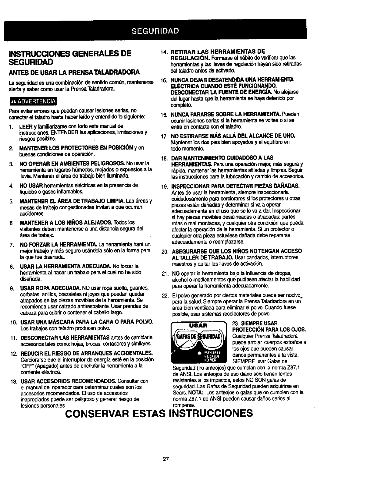
23 SIEMPREUSAR
PROTECCIONPAPALOSOJOS
CualquierPrensaTaladradora
puedearrojarcuerposextrahosa
losojosquepuedencausar
dafiospermanentesa lavista
SIEMPREusarGalasde
Seguridad (no anteojos) que cumplancon la norrna Z87.1
de ANSI. Los anteojosde uso diafiosSIotienen ]entes
resistentes a losimpactos, estos NO SON galas de
seguridad. I.as Gatas de Seguridad pueden adquirirse en
Sears. NOTA: Los anteojos o galas que no cumplen con la
norma Z87.1 de ANSI pueden causar daSosserlos al
romperse.
CONSERVAR ESTAS INSTRUCCIONES
27
REGLASDE SEGURIDADESPEC|FICAS
PARALA PRENSATALADRADOFIA
RBIJI_=I_I=K_
Porsupropiaseguddad,nobatardeusarlaPrensaTaladradorani
enchufarlahastaqueest6cornpletamenteensambladaeinstalada
deacuerdoconlasistmcciones,y hastahaberlefdoy entendido
estemanualdeinstnJcciones:
2,
3.
4.
5.
6.
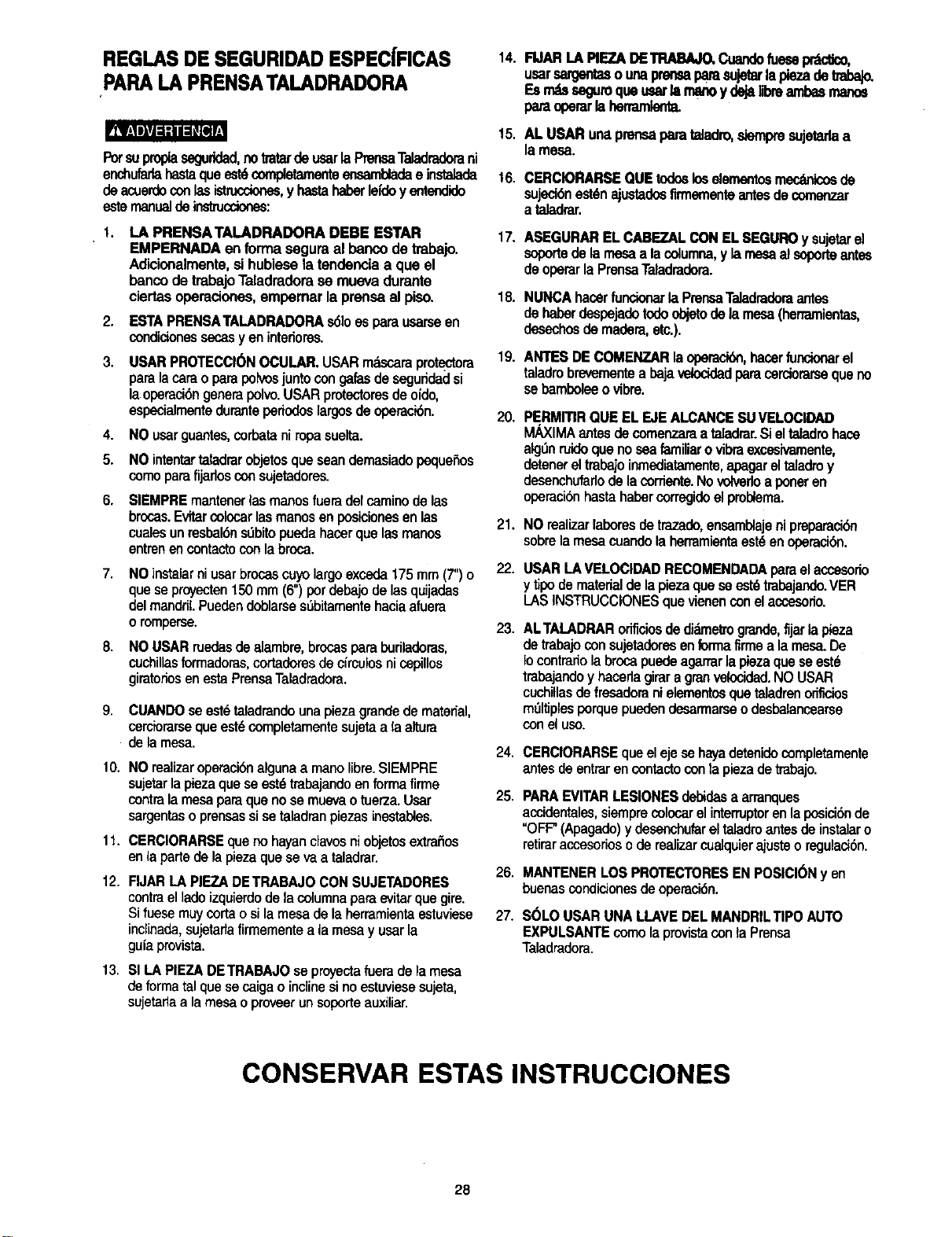
LA PRENSATALADRADORA DEBE ESTAR
EMPERNADA en formaseguraal bancodetrabajo.
Adicionalmente,sihubiesela tendenciaa que el
bancode trabajoTaladradorase muevadurante
ciertasoperaciones,empernarla prensaal piso.
ESTAPRENSATALADRADORAs61oesparaucameen
condidonessecasyen intedores.
DSARPROTECCK_NOCULAR.USARmdscaraprotectora
paralacarao parapolvosjuntocongalasdesegundadsi
laoperacibngenerapoivo.USARprotectoresdeofdo,
especialmentedurantepedodoslargosdeoperackSn.
NOusarguantes,corbataniropasuelta.
NOintentartaladrarobjetosqueseandemasiadopequerios
comeparafijarlosconsujetadores.
SIEMPREmantenerlasmanosfueradetcaminodelas
brocas.Evitarcolocarlasmanosenposicionesenlas
cualesunresbal6ns0bitopuedahacerquelasmanos
entrenencontactoconlabroca.
7.
8.
NOinstalarniusarbrocascuyolargoexceda175mm(7")o
queseproyecten150mm(6")pordebajodelasquijadas
delmandril.Puedendoblarses6bitarnentehaciaafuera
oromperse.
NOUSARruedasdealambre,brocasparaburiladoras,
cuchillasformadoras,cortadoresdecfmulosnicepillos
giratoriosenestaPrensaTaladradora.
9. CUANDOse estetaladrandounapiezagrandedematerial,
cerciorarsequeest_cornpletarnentesujetaa la altura
delamesa.
10. NOraalizaroperacibnalgunaa manolibre.SIEMPRE
sujetarlapiezaquesaest_trabajandoenforrnafirme
contralamesaparaquenosemuevaotuerza.Usar
sargentaso prensassisetaladranpiezasinestables.
11. CERCIORARSEqueno hayanclavosniobjetosextrarios
enlapartedelapiezaquesevaa taladrar.
14.
15.
t6.
17.
18.
19.
20.
21.
22.
23.
24.
25.
26.
12. FIJARLAPIEZADETRABAJOCONSUJETADORES
contraelladoizquierdode lacolumnaparaevitarque gire.
Si fuesemuycortaosilamesadelaherramientaestuviese 27.
indinada,sujetadafirmementea lamesay usarla
guiaprovista.
13. SI LA PIEZA DETRABAJO se proyecta fuera de la mesa
de forma tal que se caiga o inclinesi no estuviese sujeta,
sujetadaa la mesa o proveer unsoporteauxiliar.
FIJARLA PIEZADE"rRABAJO,Cuandofuese_,
usarsargentasounaprensaparasujetarla plezadetrabaJo.
Esn_a seguroqueusarla _ y dejalibreambasmanoe
paraoperarlaherramlerCa.
AL USARunaprensaparataJadro,siempresujetadaa
la mesa.
CERCIORARSEQUEtodosloselement.smec._nicosde
sujeci6nest6najustadosfirmementeantesdecomenzar
a taladrar.
ASEGURARELCABEZALCONELSEGUROy sujetarel
soportedelamesaa lacolumna,y larnesaalsoporteantes
deoperarla PrensaTaladradora.
NUNCAhacerfuncionarlaPrensaTaladradoraantes
dehaberdespejadotodoobjetodela mesa(henamientas,
_hos de madera,etc.).
ANTESDECOMENZARlaoperadbn,hacerfuncionarel
taladrobrevementea bajavelocidadparacarciorarsequeno
sebamboleeovibre.
PERMmRQUEELEJEALCANCESUVELOCIDAD
MAXIMAantesde comenzaraa taladrar.Sieltaladrohaca
alg_nruidoquenoseafamiliarovibraexcesivamente,
detenereltrabajoinmediatamente,apagareltaladroy
desenchufadodelacorriente.Novotverloaponeren
operaci6nhastahabercorregidoelproblema.
NOraalizarlaboresdetrazado,ensamblajenipraparaci6n
sobrelamesacuandola herramientaest_enoperacibn.
USARLA VELOCIDADRECOMENDADAparaelaccesorio
y tipode materialde lapiezaqueseest6trabajando.VER
I_ASINSTRUCCIONESquevienenconelaccecorio.
ALTALADRARorificiosdedidmetmgrande,fijarla pieza
de trabajoconsujetadoresenformafirmea la mesa.De
Iocontrariolabrocapuedeagarrarlapiezaqueseestd
trabajandoy hacerlagirara granvelocidad.NOUSAR
cuchillasdefresadoranielementosquetaladrenoriflcios
rndltiplesporquepuedendesarmarsaodesbalancearse
coneluso.
CERCIORARSEqueelejesehayadetenidocompletamente
antesde entrarencontactocontapiezadetrabajo.
PARAEVITARLESIONESdebidasa arranques
accidentales,siemprecolocarelinterruptorenlaposicibnde
"OFF"(Apagado)ydesanchufareltaladroantesdeinstalaro
ratiraraccesoriosoderealizarcualquierajusteo regulacibn.
MANTENER LOS PROTECTORES EN POSICI(_N y en
buenas condicionesde operaci6n.
SOLOUSARUNALLAVEDELMANDRILTIPOAUTO
EXPULSANTEcomolaprovistaconla Pransa
Taladradora.
CONSERVAR ESTAS INSTRUCCIONES
28
INSTRUCCIONESPARALA CONEXI6N ATIERRA
ENELEVF.N10DEUNAFALLAO MALFUNClONAMIENTO,
laconex_na_rra Ixoveeunavl'ademanorrosistenoiaparala
cordenteekY_foa,redudendoas(elriesgodechoqueel_'trico.
Estaherramientaestdequipadaconuncord6nel6ctricoqua
tieneunconductorparaconexk_na IJerraytambi#nconun
enchufeconespigaparaelmismofin.ElenchufeDEBE
conectarseenuntomacorrientequelehagajuegoy queest6
debidamenteinstaladoyconectadoa tierradeacuerdocon
TODOSloscddigosyordenanzaslocales.
NOMODIRCARELENCHUFIEPROVISTO.Sinoentraenel
tomacordente,hacerquaunelectricistacalificadoinstaleun
tomacordenteadecuado.
LACONEXJ6NINADECUADADELCONDUCTORparalJerra
deunequipopuedegenemrdesgodechoqueeldctdco.El
conductorconformaislanteverde(conosinrayasamarillas)es
elconductorparaconexibnatierra.Sielcordbnel_"tricooel
enchuferequierenreparacioneso reemplazo,NOconectarel
conductorparatierradelequipoa unterminalvivo.
AVERIGUARconunelectricistaopersonaldeserviciosise
tienecualquiardudeencuantoa la con_6n correctaa tierra
delequipo,osilasinstrucoionosparalaconexi6na tierrano
_st_nclaras.
SOLOUSARCORDONESDEEXTENSIONQUETENGAN
ENCHUFEDETRESESPIGASY UNTOMACORRIENTEQUE
_,CEPTEELENCHUFEDELA HERRAMIENTA.REPARARO
REEMPLAZARINMEDIATAMENTELOSCORDONES
DAI_ADOSO GASTADOS.
RECOMENDACIONES PARA LOS CORDONES
DE EXTENSION
Cerciorarsequeelcordbndeextensibnest_enbuenas
condiciones.AIusaruncord6nde extensi6n,cerciorarseque
seaIosuficientemente_]mesoparaconducirlacorrienteque la
herramientademandera.Uncordensubdimensionadecausar-_
unacaideen elvoltajede la lineacausandounap_rdidade
cotenciay recalentamiento.Latabtaqueaparecoenesta
paginamuestraloscalibrescorrectosde loscordonesseg_n
suextensi6ny elamperajerequeddopot laherramientaque
apareceen la placa.Encasode dude,usarel siguientecalibre
n_s grueso.CuantomenoretnL_merodelcalibre,mayorel
di_,metrodelalambre.
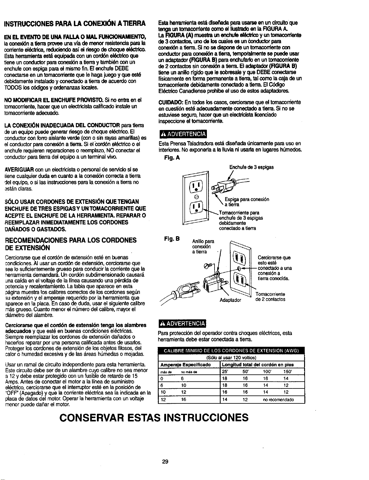
Estaherramlentaostd_ parausarseenundrcuitoque
teogauntomacorrlentecomoelilustradoeftlaRGURAA.
La RGURA(A)muestmunenchufeel_K_o y untornacontente
pe 3contactos,unode loscualesesun_onductorpare
cor_J6na _erra.Sinosedisponede untomacordentecon
conductorparaconooddna _erra,tempoPalmentesepuedeusar
unadaptader(RGURAB)paraenchufarfoenuntomacorriente
de 2 contactossinconex_ a lJerra.Eladaptader(RGURA13)
liene unanillodgidoquelesobresaley queDEBEconectarse
fisicameflteenformapermanen_a IJerra,talcomolacajade un
tomaconientedebidamenteconectadoa_erra.ElC6digo
EldctricoCanadienseprohibeelusodeestosadaptadere_
CUIDADO:Entodo6loscasos,carciorarsequeel tomacorriente
encuesti_ est6adecuadamenteconectadoa tierra.Sinose
estuvioseseguro,hacerquaunelecldcistalicenciado
inspeccioneeltomacordente.
EstaPrensaTaladraderaestddiseSadadnicamenteparausoen
intedores.Noexponedaa laIluvianiusarlaenlugaresh_medes.
Fig. A
Enchufede3espigas
®
,_ eJ'_ _Temacorriente para
enchufede3 espigas
debidamente
conectadoatierra
Fig. B cAoninllOxiPara
Adaptador
Cerciorarseque
estoest_
-- conectadoa una
conexi6na
tierraconocida.
Tomacorriente
de 2 contactos
Cerciorarsequael cord6ndeextensi6ntenga losalambres
adecuadosy queest_en buenascondicioneseldctdcas.
Siemprereemplazarloscordonesdeextensi6ndaSadoso
hacerlosrepararperunapersonacalificadaantesdeusarlos.
Protegerloscordenesdeextensi6ndelosobjetosfilosos,del
calorohumedadexcesivay delasareash_medaso mojadas.
Usar un ramal de circuito independiente para esta herramienta.
Este circuito debe ser de un alambre cuyo calibre no sea menor
a 12 y debe estar protegido con un fusi_e de retardo de 15
Amps. Antes de conectar el motor a la Iinea de suministro
el@ctrico,carciorarse que el interruptor est@en la posici6n de
='OFF"(Apagado) y que la corriente el_}ctdcasea la indicada en la
placa de datos del motor.Operar la herramienta con un voltaje
manor puede daSar el motor.
Paraproteccidedeloperadercontrachoquesel_ctdcos,esta
herramientadebeestarconectadaa tierra.
ii#;! i i:t 11=l_ydl_ll_[el i] =lllo],,-,ll(o]=1i[t]# i_.-tle]=1_:11=1_k"t[_]_ll_|_f[_l
($61oal usar 120 volUos)
Amperaje Especificado
m_s de no rods
0 6
6 10
10 12
12 16
Longltud total del cordbn en pies
25' 50' 100' 150'
18 16 16 14
18 16 14 12
16 16 14 12
14 12 norecomendado
CONSERVAR ESTAS INSTRUCCIONES
29
ACCESORIOS DISPONIBLES
$61ousaraccesoriosrecomendadosparaestaPrensa
Taladradera.Seguirlosinstrucoionesqueacompa_ana los
accesorios.[] usodeaccesoriosinadecuadospuede
generarriesgos.
VisitarelDepartamantode Ferretedadela liendaSears
mdscercanaover elCatdlogode HerramientasEI6cbicas/
Neun_ticasy ManualesdeSearsparalossiguiantos
_cesorios:
BrocasparaTaladro
• Sujetadory Gu(a
PrensasparaPransaTaladradera
• JuegodeMortajay EspigaparaPrensa
Taladradora
• JuegodeSujetadores
• Cincely BrocastipoMortajay Espiga
• TamboresLijadores
RusdasPulidorasde hasta4" (10cm)de
DidmetroM_ximo
• SierraparaOrificiosdehasta2-1/2' (6.35cm)
DESEMBALAJE Y VERIFICACI( N DEL
CONTENIDO
Sifaltasanpiezasohubiesenpiezasder3ades,noenohufarla
PrensaTaladradorahastaconseguirlaspiezasfaltantesode
reemplazarlasda_adasy basrahabercompletadeelensam_aje.
DesempaquetarcuidadosamentelaPrensaTaladradoraytodas
suspartesyverificadascontralarelaci6nqueestda
con_nuaci6n.
ParaprotegerlaPrensaTaladraderacontralahumedad,las
partesmaquinadashansiderecubiertasconunacapaprotectora
quesadeberemoverconunpasohumedecidoconkerosene
oWD-40.
rRBligPJ_l_J_l_
Paraevitarincendioso reacoionest6xicas,nuncausargasolina,
naffa,acetona,tinerparalacaso solventessimilaresdealta
volatilidadparalimpiarlaPrensaTaladradora.
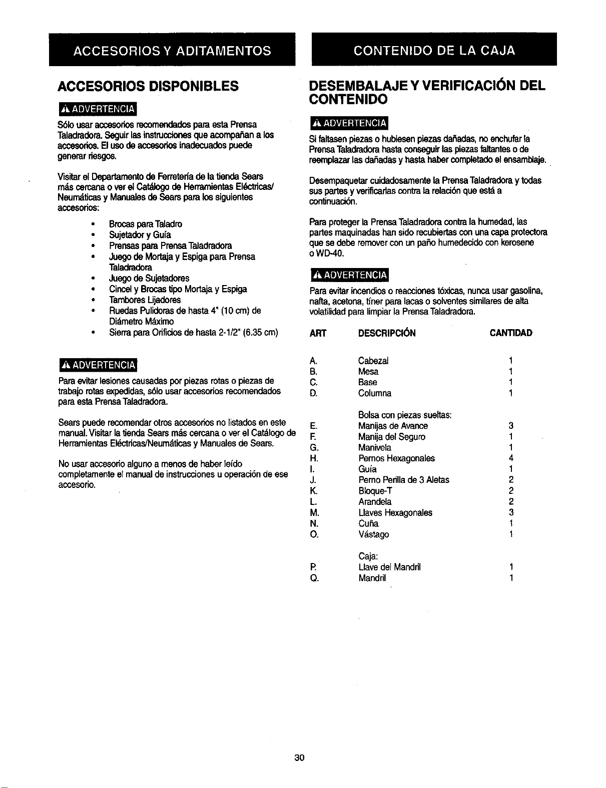
ART DESCRIPCI(_N CANTIDAD
ParaovitarIosionoscausadasporpiezasrotaso piezasde
trabajomtasexpedidas,s61ousaraccesoriosrecomendados
paraestaPrensaTaladradora.
Searspuederecomenderotrosaccesoriosnolistadoseneste
manual.VisitarlatiendaSearsn_s cercanaoverelCatdlogode
HerramientasEldctdcas/Neumdticasy ManualesdeSears.
Nousaraccesorioalgunoa manosdehaberleido
completamenteelmanualdeinstrucoionesuoperaci6ndeese
acoesorio.
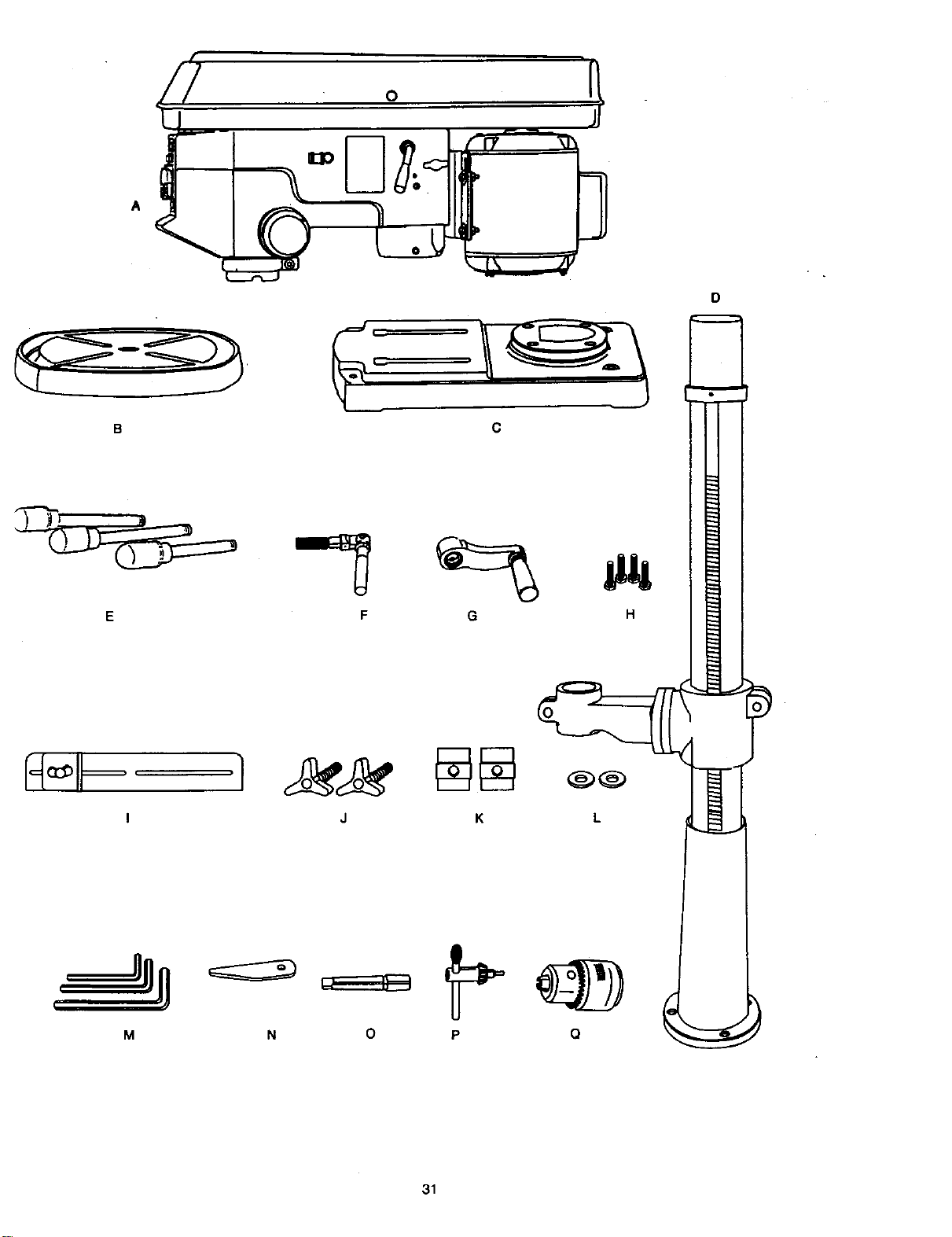
A. Cabezai
B. Mesa
C. Base
D. Columna
E.
E
G.
H.
I.
J.
K.
L
M.
N,
O.
P.
Q.
Balsaconpiezassueltas:
Manijasde Avance
Manijadel Seguro
Manivela
PernosHexagonales
Guia
PernoPerillade3 Aletas
Bloque-T
Arandela
LlavesHexaganales
Cuba
V_,stago
Caja;
Uave del Manddl
Mandril
1
I
1
1
3
1
1
4
1
2
2
2
3
1
I
3O
o
A
H_ _ .1
I
M
C
F G H
J K L
0
31
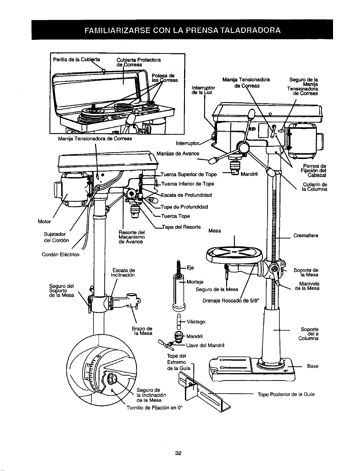
Perilla de la Cubi_
Cubierta Protectora
Poleas de
Interruptor
de la Luz
Manija Tensionadora Segurodela
Manija
Tans_nadoia
de Co_eas
ManijaTensionadora de Correas
Motor
Sujetador
de1Cordbn
Cordbn El_,_,ctdco
Segurodel
Soporte
de ia Mesa
Resole del
Mecanismo
de Avance
Escala de
Inclinaci6n
Manijas de Avance
Profundidad
_pe
tpa del Resorte
Mesa
Eje
Mortaja
Seguro de la Mesa
Drenaj,
A
Brazo de _'--
Vdstago
la Mesa __ Mandril
Llavedel Mandril
Tope del
Extremo
de la_
Segurode J ' _
la Inclinacibn I /J,_'"_
e,aMosa v
Tomillo de Fijacibnen 0_
Pemos de
Fijacibndel
Cabezal
Collarfnde
la Columna
Cremallera
Soporte de
la Mesa
Manivela
de la Mesa
Soporte
dela
Columna
Base
Tope Posterior de ia Guia
32
BASE- ,_porla laPreneaTeladradora.Paramayore6tabilidad
provisladeodfick_paraempemarlaPrensaTalaclradom81
piso.(Ver"lnstruccionesdeSeguridadEspecificasparaPransas
Teladraden ').
MATERIALDEAPOYO- Unapiezade rnaderadedesachoque
sacolocaentrelapiezaquesatmbajay lamesa.Lamademde
apoyoevitaqueseas_llelamaderaquesetaladracuandola
brocalaal_a_eza.Tambidnevitataladrarlasuperl_iedela
mesa.
CUBIERTAPROTECTORADECORREAS- Cubrelaspoleasy
correasdurantelaopemci6ndelaPrensaTeladradora.
TENSI6N DELASCORREAS- Refedrsea lassecdones:
=Ensamblaje"e =lnstalaci_yTans_ de Correas".
MANUATENSIONADORADECORREAS- Girarlamanijaen
el sanlidedelrelojperutensioharlacorreaycontmelsentidodel
relojparaaliviarlatensk_.
SEGURODELAMANUATENSIONADORADECORREAS-
Ajustandolasmanijassafijaelsoportedelmotory lamanija
tensionadoramanteniendoladistanciaytensi6ncorrectade la
coffee.
ESCALADEINCLINACI_NDELAMESA- Muestralosgrades
deinclinaci6ndela mesaparelostrabajosde pianoindinado.La
escalaestdmontadaa uncostadodelbrazo.
MANDRIL- Sujetala brocateladradoraocualquierOtTO
accesoriorecomendadeparerealizerlostrabajosdesaados.
LLAVEDELMANDRIL- Usagavequesaautoeyectadel
mandrilcuandoselesuelta.Estaacci6nest_disafiadapara
evitarquelaIlavesalgadisparadadelmandrilcuandoseactive
laherramienta.NousarIlavessubstitutas.Sisedeteriorao
pierde,ordenarunaIlavenueva.
COLUMNA - Es untubo queconecta el cabezal, la mesay la
base Loamfacilitarsu alineamientoy movimianto.
COLLARiNDELA COLUMNA- Sujetala cremelleraala
columna.Lacremallerasemantienem6vilenelcollan'npara
perm_rlosmovimientosdelsoportedelamesa.
SOPORTEDELA COLUMNA- Soportalacolumna,guiala
cremellemy proveeoriflciosparemontarlacolumnaa
labase.
TUERCASDETOPEDELAESCALADEPROFUNDIDAD-
Fijaelejea lapmfundidadseleccionada.
ESCALADEPROFUNDIDAD-Indica la profundideddelorificio
queseestataladrando.
BROCA - La herramientaque sa usaen la PrensaTaladradora
parehacer los oriflciosen la pieza de trabajo.
INTERRUPTORDELTALADRO- Tieneundispositivode
seguro.Estedispositivoestddisefiadeparaevitarelusono
autorizadoy pesiblementepeligrosoper nifiosyotraspersonas.
InsertarlaIlaveenelinterruptory girarlaparaponerelteladroen
opemci<_n.
VELOClDADDETALADRADO- Se cambiacolosandolacorrea
ancualquierade laspoleas.VerlaTablede Velocidadesenla
perteintemade lacobiertapmtectorade lascorreas.
MANUASDEAVANCE- Muevenelmandrilhaciaarribay
abajo.Sifuesenecesario,sapuedenquitarunaodosmanijas
cuandolapiezadebabajoseade unaformataninusualque
interfieraconlasmanijas.
GU_A- Se montaenlamesay sieveparealinearlap_ezade
trabajooparehacerperforacionesrepetitivasenformardpide.Es
desmontable.Sacarlacuandointerfiemconlosaccesoriosdela
PrensaTaladradora.
SEGUROSDELCABEZAL- Fijaelcabezalan la columna.
SIEMPREfijarelcabezalan posici6nconlosseguroscuandose
operelaPrensaTeladradora.
CREMALLERA- Funcionaancombinacibnconelmecanismo
deengranajes.Sirveparefacilitarla elevacibndela mesa
operandea manelamanivelade lamesa.
REVOLUCIONESPORMINBTO(R.P.M.)- ElnOmemde
vueltascompletasqueunobjetogiratoriodaenunminuto.
VELOCIDADDELEJE - LasR.RM.deleje.
TAPADELRESORTE- Regulalatensi6ndelresortedela
mortaja.
SEGURODELSOPORTEDELA MESA- AIajustarlosagums
seajustaelsoportedelamesaala columna.Siempmtenerlo
puestocuandosaoperelaPrensaTaledmdom.
MESA- Proveeunasuperficiedetrabajoparaapoyarla pieza
detrabajo.
BRAZODELAMESA- Se proyectamdsanddelsoportedela
mesaparemontar[amesay alinearia.
PERILLADESEGURODELA INCLINACI(_NDELAMESA-
Fijalamesaancualquierdngulode inclinaci6nde0°a45°.
MANIVELADELA MESA- SirVeparasubiry bajarla mesa.
Girarlaenelsantidodelrelojpareelevarlamesa.Debesottarse
elsegurodelsoporteantasdeoperalamanivela.
SEGURODELAMESA- Fijala mesaenpesici6ndespuesde
colocarlaencualquierpesici6n.
SOPORTEDELA MESA- Sedesplazaenlacolumnapare
sopodarelbrazedelamesay lamesa.
DRENAJEROSCADODE(5/8")- Instalaruntubometal
(roscado)enelorificioroscadoparadrenarelexcesodeaceitea
uncontenedor.ParaIograrunasuperficiesindrenaje,instalarun
taponroscadodemetal.Noseincluyeneltubonieltapbn.
PIEZADE TRABAJO - Elmaterialquesetaladra.
33
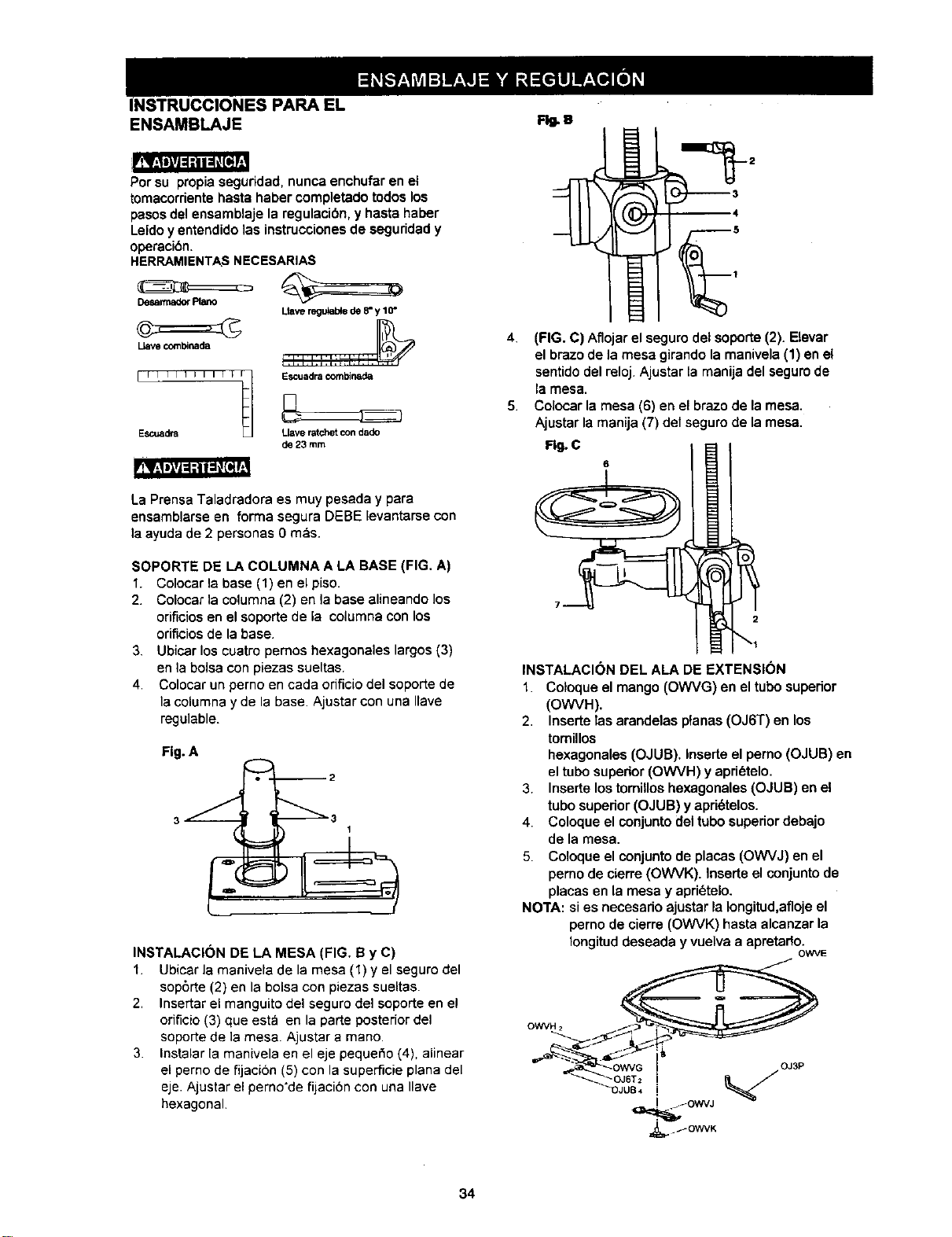
INSTRUCCIONES PARA EL
ENSAMBLAJE FlU.U
rfq_igJ_l_iK_d_
Per su propia seguddad, nunca enchufar en el
tomacorriente haste haber completado todos los
pesos del ensamblaje la regulacibe, y haste haber
Leido y entendido ]as instrucciones de seguddad y
operaci6n.
HERRAMIENTASNECESARIAS
DesarmadorPiano
Uave combinada
Llaveregufabdede 8"y 10"
[ I I I I I I I I I _ I1 I EscuadracomNnada
Escuadra Llave ratchet con dad<)
_23mm
La Prensa Taladradora es muy pesada y pare
ensamblarse en forma segura DEBE levantarse con
la ayuda de 2 personas 0 mas.
SOPORTE DE LA COLUMNA A LA BASE (FIG. A)
1. Colocar la base (1) en el piso.
2. Colocar ]a columna (2) en la base alineando los
orificiosen el soporte de la columna con los
orificiosde la base.
3. Ubicar los cuatro pemos hexagonales largos (3)
en la boise con piezas sueltas.
4. Colocar un perno en cada orificiodel soporte de
la columna y de la base Ajustar con una Ilave
regulable.
Fig. A
INSTALACI(_N DE LA MESA (FIG. B y C)
1. Ubicar la manivela de la mesa (1) y el seguro del
sop6rte (2) en la boise con piezas sueltas.
2. Inserter el manguito del seguro del soporte en el
orificio(3) que estb en la parte posteriordel
seporte de ]a mesa Ajustar a mane.
3. Instalar la manivela en el eje pequet_o(4), alinear
el perno de fijacion (5) con la superScie plane del
eje. Ajustar el perno'de fijaci6n con una Ilave
hexagonal
4. (FIG. C) Aflojar el seguro det soporte (2). Elevar
el brazo de la mesa girando la manivela (1) en el
sentido del reloj. Ajustar ta manija del seguro de
la mesa.
5. Colocar la mesa (6) en el brazo de la mesa.
Ajustar la manija (7) del seguro de la mesa.
Fig. C
6
INSTALACI(_N DEL ALA DE EXTENSION
1. Coloque el mango (OWVG) en el tubo superior
(OWVH).
2. Inserte las arandelas pfanas (OJ6T) en los
tomillos
hexagonales (OJUB). Inserte el pemo (OJUB) en
el tubo superior (OWVH) y apri_telo.
3. Inserte los tomillos hexagonales (OJUB) en el
tubo superior (OJUB) y apd6telos.
4. Coloque el conjunto del tubo superior debajo
de la mesa.
5. Coloque el conjunto de places (OWVJ) en el
pemo de cierre (OWVK). Inserte el conjunto de
places en la mesa y apd6telo.
NOTA: si es necesado ajustar la Iongitud,afloje el
perno de cierre (OWVK) hasta alcanzar la
Iongitud deseada y vuelva a apretado.
OWVE
OWVH 2
34
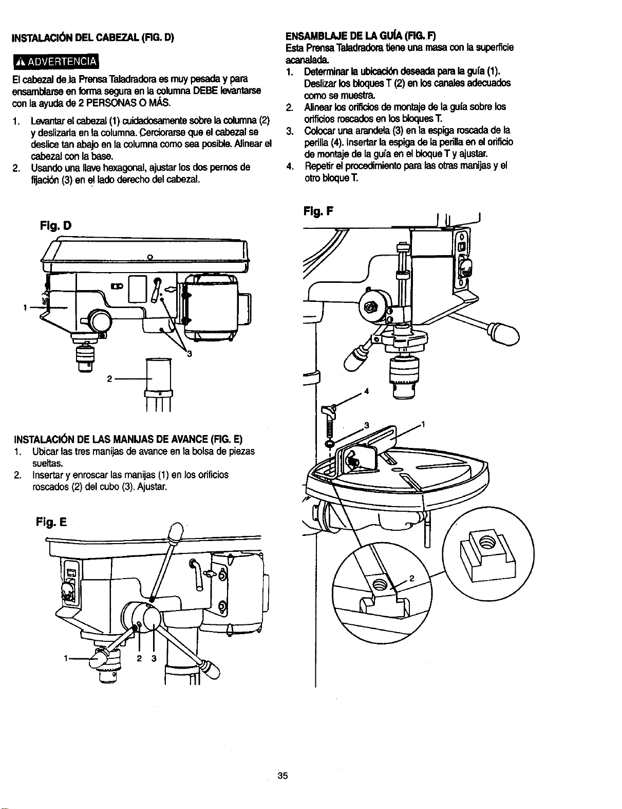
INSTALACI6N DEL CABEZAL(FIG. D)
ElcabezaldeJaPrensaTaladradoraes muypesaday para
ensamblarseenforrnaseguraen lacolumnaDEBElevantarse
conlaayudade2 PERSONASO IV_S.
1. Levantarelcabezal(1) cuidadosamentesobrelacolumna(2)
y deslizarlaenlacolumna.Cerciorarseque elcabezalse
deslicetanabajoenla columnacomosea posible.Alinearel
cabezalconlabase.
2. Usandouna,ave hexagonal,ajustarlosdospernosde
fijacibn(3) enel ladoderechodel cabezal.
ENSAMBLAJEDE LA GU_ (RG. F)
EstaPrensaTaladradom_eneuna masaconlasuperficie
acanalada.
1. Determinarla ubicack_deseadaparalagufa(1).
DeslizarlosbloquesT (2) enloscanalesadecuados
comosemuestra.
2. Alinearlosorificiosde montajedelagufasobrelos
orificiosroscadosen losbioquesT.
3. Colocarunaarandela(3) en laespigaroscadadela
perilla(4).Insertarlaespigadelapedllaenelorifido
demontajedelaguiaene]bloqueTy ajustar.
4. RepelJrel procedimientoparalasotrasmanijasy el
otrobloqueT.
Fig. D
Fig. F
INSTALACI(_NDE LAS MANIJASDEAVANCE(FIG.E)
1. Ubicarlastresmanijasde avariceenla bolsade piezas
sueltas.
2. Insertary enroscar las manijas (1) en losorificies
roscados(2) del cubo(3).Ajustar.
F
35
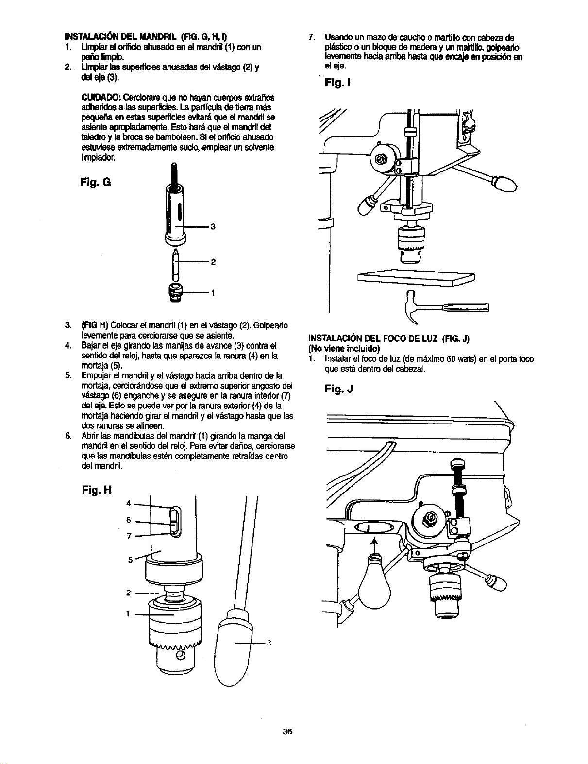
INSTALACI(_)NDELMANDRIL(RG.G,H,I)
1. Umplarelorifldoahusadoenetmandril(1)conun
pasolimp_o.
2. Umpiarlassuperfldesahusadasdelwf_tago(2)y
deleje(3):
7. Usandounrnazodecauchoo rnartnoconcabezade
pl_dcoounbloquedemaderayunrna_llo,golpearlo
levementehadaardbahastaqueencajeenposicklnen
eleje.
Fig. I
CUIDADO:Cercioramquenoha/ancuerposextr'a_os
adheridosalas superficies.I.apartfculadelJermms
peque_aenestassuperficiesevitar_queelmandrilse _-_
_mienteapropiadamente.Estohardqueelmanddldel
taladroy labrocasebamboleen.Sielorifidoahusado
estuvieseextrernadamentesucio,ernplearunsolvente
limpiador.
3. (FIGH)Colocarelmandril(1) enel v_tago (2).Golpearlo
levementeparacerciorarsequeseasiente.
4. Ba'larelejegirandolasmanijasdeavance(3)contrael
senfidodelreloj,hastaqueaparezcalaranura(4)enla
mortaja(5).
5. Empujarelmandnly elvastagohaciaarribadentrodela
mortaja,cercior_doseque elextremosuperiorangostodel
vdstago(6)enganchey seasegureenlaranurainterior(7)
deleje.Estosepuedeverporlaranumexterior(4)dela
mortajahaciendogirarelmandrily elvdstagohastaquelas
dosranurassealineen.
6. Abrirlasmandll_ulasdelmandr;I(1)girandolamangadel
mandrilenelsentidodelreloj.Pareevitarda_s, cerciorarse
quelasmandibulasest_ncompletamenteretmfdasdentro
delmandril.
L=J
INSTALACI(_NDELFOCODELUZ (RG.J)
(Novieneincluido)
1. Instalarelfocodeluz(demdximo60wars)enelportafoco
queestadentrodelcabezaL
Fig. J
Fig. H
36
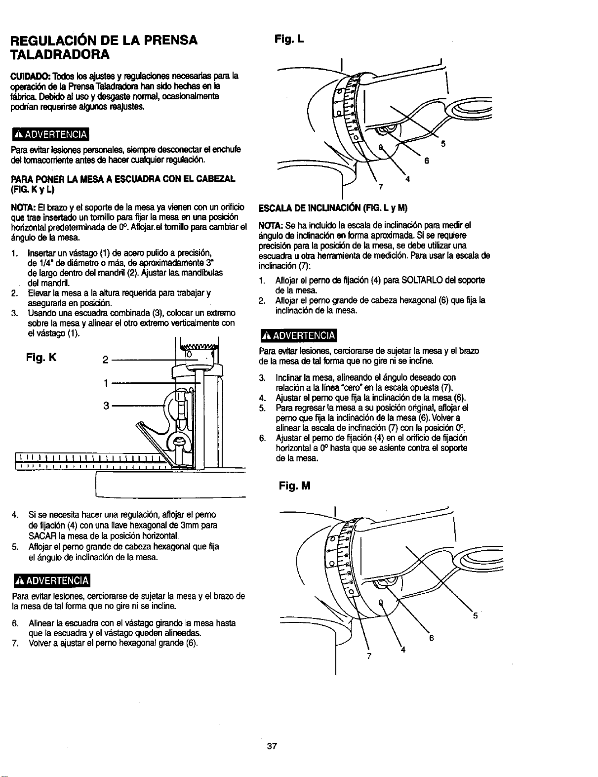
REGULACI6N DE LA PRENSA
TALADRADORA
CUIDADO:Todoslosajustesyregulacionesnecesariasparala
operesibndelaPrensaTeladradorahansidohechesenla
f_brica,DelYdoalusay desgestenormal,ocask_almente
podrfanrequedrseelgunosreajustes.
Paraevitarlesionespersonales,siempredesconectarelenchufe
deltomacorrienteantesdehasarcualquierregulacibn.
PAPAPONERLAMESAA ESCUADRACONELCABEZAL
(RG. Ky L)
NORA:Elbrazo y elsoportede la mesa ya vienen con unorificio
que traeinsertadoun tomilloparafijarlamesa en una posici6n
horizontalpredeterminadade 0°. Aflojar.eltornilloparacambiarel
_ngulo de la mesa.
1. Insartarunv_stago(1)de aceropulidoa precisi6n,
de1/4"dedidmetroomds,deaproximademente3"
delargodentrodelmandril(2).Ajustarlasmandibulas
• delmandril.
2. Elevarlamesaa laalturarequeridaparatmbajary
asagurarlaenposici6n.
3. Usandounaescuadracombinada(3),colocarunextremo
sobrelamesay alinearelotroextzernovertJcatmentecon
elv_stago(1).
I I_..._._.J
Fig. K 2 _:_
I t_5--- -- __
I I _ I _ t I I I I I I/
4. Sisa necesitahaceruna regulaci6n,aflojarelpemo
defljaci6n(4)conunaIlavehexagonalde3mmpara
SACARla mesadela posici6nhorizontal.
5. Aflojarel pernograndede cabezahexagonalquefija
elangulode inclinaci6ndela mesa.
Paraevitarlesiones,cerciorarsedesujetartamesay elbrazede
la mesade talformaque nogireni seincline.
6. Alinaarlaescuadraconelv_stagogimndela mesahasta
quela escuadrayel vdstagoquedenalineadas.
7. Volveraajustarelpernohexagonalgrande(6).
Fig. L
5
6
4
7
ESCALADEINCLINACI6N(FIG,Ly M)
NOTA: Se ha induido laescalade inclinaci6n paramedirel
&ngulo de indinaci6nen formaaproximada.Si sa requiem
precisi6nparala posici6nde la mesa, se debe utilizaruna
escuadra uotra herramientade medici6n.Para usarla escala de
inclinaci6n(7):
1. Aflojarelpernodefljaci6n(4) paraSOLTARLOdelsoporte
delamesa.
2. Aflojarelpernograndedecabezahexagonal(6)quefijala
inclinaci6ndelamesa.
Paraevitarlesionas,cemiorarsadesujetarla mesay elbraze
dela mesadetalformaquenogireniseincline.
3. Inclinarlamesa,anneandoel_,ngulodesaadocon
ralaci6na lalinea"sam"enla escalaopuesta(7).
4. Ajustarelpernoquefija lainclinaci6nde la mesa(6).
5. Pararegresarla mesaa suposial6nodginel,aflojarel
pemoquefljala inclinaci6nde la mesa(6).Volvera
alinearla escalade indinaei6n(7)conlaposici6n0°,
6. Ajustarelpemode fijacibn(4)enelorificiode fijaci6n
horizontala 0° hastaquesaasientecontrael sogorte
de lamesa.
Fig. M
5
6
37
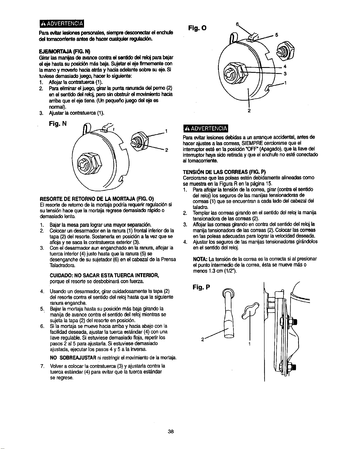
rRB[i_PJ_l_e[
Parae_r lesionespecsona_ siempredesco_ el enchub
delton_,co,-den_antesdehanercualquierreguladdn.
F OnT A (RG.N)
Girarlasmanijasdeavancecontrael sanlJdodelrelojparebajar
elejehastesuposiciderndsbaja.Sujetarel ejefirmementecon
lamanoymovedohaciaatrdsy haciaadelantesobresusje.Si
tuviesedemasiadojuego,hacerIosiguiente:
1. Aflojarb contratuerca(1).
2. Paraeliminarel juego,girarlapuntaranuradadetperno(2)
enelsentidodelreloj,perusinobstruirelrnovimientohada
arribaqueelejetiene.(Unpeque6ojuegodelejeas
normal).
3. Ajustarlacontmtuerca(1).
Fig. N
RESORTEDE RETORNODELAMORTAJA(FIG.O)
Elresortederetomodelamortajapodr_arequerirregulacibnsi
sutensi6nhaosquelamortajaregrasedemasiadordpidoo
demasiadelento.
1. Bajarla mesapareIograrunamayorseparaci6n.
2. Colocarundesarmadorenlaranura(1)frontalinferiordela
tape(2)del rasorte.Sostenedeenposici6nala vezquese
aflojay sesacalacontmtuercaexterior(3).
3. Coneldesarmadoraunenganchadoenlaranura,aflojarla
tuercainterior(4)justohastaquelaranura(5)sa
desenganchede susujetador(6)enelcabezaldelaPreosa
Taladradora.
CUIDADO: NO SACAR ESTA TUERCA INTERIOR,
porqueel rasorlese desbobinardcon fuerza.
4. Usandoundesarmador,girarcuidadosamentelatape(2)
delresortecontraelsentidodelrelojhastaquelasiguiente
ranuraenganche.
5. Bajarlamortajehastasuposici6nrodsbajagirandola
manijadeavancecontraelsentidodelrelojmientrasse
sujetalatapa(2) delresorteenposici6n.
6. Sila mortajasemuevehaciaarribay haciaabajoconla
facilidaddeseade,ajustarla tuercaestdndar(4)conuna
Ilaveregulable.Siestuviasedemasiadofloja,repetirlos
pasos2 al5 paraajustarla.Siestuviasedemasiado
ajustade,ejecutarlospasos4 y5 ala inversa.
7.
NO SOBREAJUSTARnirestringirelmovimientodelamortaja.
Volvera colocarlacontratuerca(3)yajustarlacontrala
tuercaestandar(4)paraevitarquelatuercaestdndar
se regrase,
Fig. O
Pareevitarlesionesdsbidesa unarranqueaccidental,antesde
hacerajustesalasconeas,SIEMPREcerciorarsequeel
intermptore_6 en laposici6n=OFF"(Apagado),quelaIlavedel
interruptorhayasidoretiraday queelenchufenoest6conectado
altomacorTiente.
TENSI(_NDEI.AS CORREAS(FIG.P)
Cerciorarsequelaspoleasest6ndebidamentealineadascoma
semuestraenlaRguraRenlapdgina15.
1. Pareaflojarlatensi6nde lacorrea,girar(contraelsen_do
delreloj)lossegurosdelasmanijastensionadorasde
correas(1)queseencuentranacedeladedelcabezaldel
taladro.
2. Templar[ascorreasgirandoenelsentidodelrelojlamanija
tensionadoradelascorreas(2).
3. Aflojarlascorreasgirandoencontradelsen_dodelrelojla
manijatensionadoradelascorreas(2).Colocarlascorreas
enlasIx)leasadecuadasparaIograrla velocideddaseada.
4. Ajustarlossegurosdetasmanijastensionadorasgirdndolos
enelsentidodelreloj.
NORA:Latensi6nde lacorreaeslacorrectasialprasionar
elpuntointermediodelacorrea,_stase muevemdso
menos1.3cm(1/2").
Fig. P
38
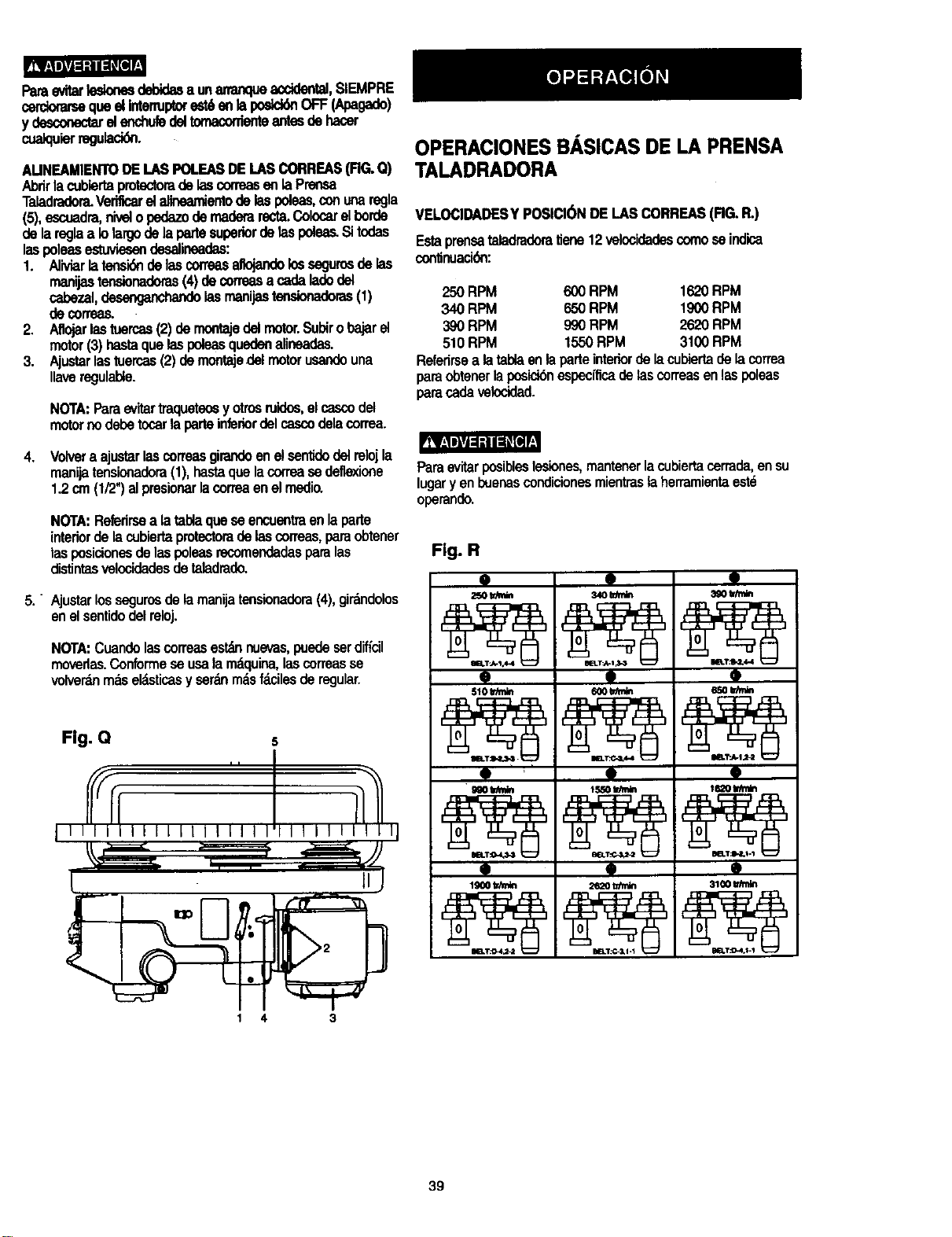
Paraevitartesionesdebidasa unananqueacddental,SIEMPRE
cerdomrsequeelIntenupexestdenlaposid6nOFF(Apagado)
y desconecWelenchuledeltomaconienteantesdehacer
cualquierregulacidn.
AUNEAMIENTODELASPOLEASDE[.ASCORREAS(FIG.Q)
AbrirlacubiertaprotectomdelascorreasenlaPrensa
Taladradora.Verificarelalineamientodelaspoleas,conunaregla
(5),escuadra,nive;opednTodemaderarecta.Colocarelborde
delareglaa Iolargodelapartesupedordelaspoleas.Sitodas
laspoleasestuviesendesalineadas:
1. Aliviarlatensi6ndelascorreasaltojandolossegurosdelas
manijastensionadoras(4) decorreasa cadaladodel
cabezal,desenganchandolasmanijastensionadoras(1)
decorreas.
2. Aflojarlastuercas(2)demofltajedelmotor.Subirobajarel
motor(3)hastaquelaspoleasquedenalineadas.
3. Ajustarlastuercas(2) demontajedelmotorusandouna
gaveregulable.
NOTA:Paraevitartraqueteosyotrosruidos,elcascodel
motornodebetocarlaparteinfenordelcascodelacorrea.
4. Volvera ajustarlascorreasgirandoenelsentidodelrelojla
manijatensionadora(1),hastaquelacorreasedefle_ione
1.2cm(1/2")alpresionarlacorreaenelmsdio.
NOTA:Refedrsea latablaquese encuentraenlaparte
interiordelacubiertaprotectomdelascorreas,paraobtener
lasposidonesdelaspoleasrecomendadasparalas
distintasvelocidadesdetaladrado.
5. " Ajustarlossegurosdelamanijatensionadora(4),girdndolos
enelsentidodelreloj.
NOTA:Cuandolascorreasestdnnuevas,puedeserdificil
moverlas.Conformeseusalamdquina,lascorreasse
volverdnmaseldsticasy serdnmdsfdcilesderegular.
Fig. Q s
OPERACIONESBASICASDE LA PRENSA
TALADRADORA
VELOClDADESY POSlCI(_NDEI.ASCORREAS(RG.R.)
Estaprensataladmdomtiene12velocidadescomoseindica
continuaciOn:
250RPM 600RPM 1620RPM
340 RPM 650RPM 1900RPM
390RPM 990RPM 2620RPM
510RPM 1550RPM 3100RPM
Referirsea latabtaenlaparteinteriordelacubiertadelacorrea
paraobtenerlaposicibnespecfficadelascorreasenlaspoleas
paracadavelocidad.
Paraevitarpo_ibleslesiones,mantenerlacubiertacerrada,ensu
lugary enbuenascondicionesmientraslaherramientaestd
operando.
Fig. R
9 9
250 tdmin 340 tdndn
Ip •
9 =' •
gQO_ 1_ _mln
o 9
9
9
9
9
3100 tdmln
1 4 3
39
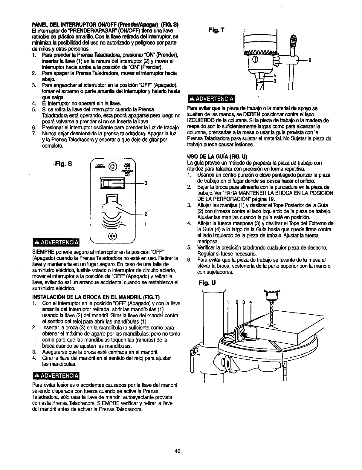
PANELDELINTERRUPTORON/OFF(PrenderlApegar)(RG. S)
[] intermptorde"PRENDER/APAGAR'(ON/OFF)tleneunanave
retlrabledepl_=_:o=na,'t_ Conlallavere_adadelIntermptor,se
rn]nimizalapos_lidaddelusonoautodzadoy pellgrosopotparte
denii_osy otraspersonas.
1. ParaprenderlaPrensaTeladradora,presionar"ON"(Prender),
insertarlaIlave(1) enlaranuradelinterruptor(2) ymoverel
interrupterhaciaarribaa laposici6nde"ON"(Prender).
2. ParaapagarlaPrensaTeladradora,moverelinterruptorhacia
abajo.
3. Paraengancharelinterruptorenlaposic_n'OFF"(Apagado),
tomarelextremooparteamarilladelinterruptory halarlohasta
queselga.
4. ElinterruptornooperardsinlaUave.
5, SisereliralaIlavedelinterruptorcuandolaPrensa
Taladradoraestdoperando,dstapodrdapagarseperoluegono
pod_volversea prendersinoseinsertalaIlave.
6. Presionarelinterruptoroscilanteparaprenderlaluzdetrabajo.
7. Nuncadejardesatendidalaprensataladradora.Apagarlaluz
y laPrensaTaladradorayesperura quedejedegirarper
completo.
.Rg. S
f
m3
m2
DI
SIEMPREponerlesaguroalinterrupterenlaposici6n"OFF"
(Apagado)cuandelaPrensaTaladraderanoest_enuso.Retirarla
llavey mantenerlaenuntugarseguro.Encasodeunafallade
suministroel6ctrico,fusiblevoladeointenuptordecircuitoabierto,
moverelinterruptera laposici6nde"OFF"(Apagado)y retirar]a
Ilave,evftandeas{unarranqueaccidentalcuandose restaUezcael
suministroel_ctdcc.
INSTALACI(_NDELABROCAENELMANDRIL(FIG.T)
1. Conelinterruptorenlaposici6n"OFF"(Apagado)yconla Ilave
amarinadelinterruptorretirada,abdrlasmandll_ulas(1)
usandolaIlave(2)delmandrfl.GirarlaIlavedelmandrilcontra
elsentidodelrelojparaabrirlasmandll_ulas(1).
2. Insartarlabroca(3) enlarnandtl_ulaIosuflcientacomopara
obtenerelmdximodeagarreporlasmandl_ulas;peronotanto
comeparaque lasmandibulastoquenlas(ranuras)dela
brocacuandoseajustenlasmandibulas.
3. Asegurarseque labrocaest_centradaenelmandril.
4. Girarla Ilavedelmandrilenelsentidodelrelojparaajustar
lasmandibulas.
Fig. T
12
Paraevitarquela piezadetrabajoo larsaterialde apoyose
sueltende lasmanos,saDEBENposicionarcontraellado
IZQUIERDOdelacolumna.Silapiezadetrabajoolamaderade
respaldosonIosuficientementelargascomoparaalcanzarla
columna,prensarlasa lamesaousarlaguiaprovistaconla
PrensaTaladradoraparasujetarelmateriel.NoSujetarlapiezade
trabajopuedecausarlesiones.
USODELAGU[A(RG. U)
Laguiaproveeunm6tododeprepararlapiezadetrabajocon
rapidezparataladmrconprecisi6nenforrnarelxYl_dva.
1. Usandouncentropunz6noclavopuntiagudopunzarlapieza
detrabajoenellugardondese deseahacerel orificio.
2. Bajarlabrcoaparaalinearlaconlapunzaduraenlapiezade
trabajo.Ver"PARAMANTENERLABROCAENLAPOSICI(_N
DELAPERFORACI_N"pdgina19.
3. Aflojarlasmanijas(1)ydesnzarelTopePcoteriordelaGuia
(2)confirmezacontraelladoizquierdodelapiezadetrabajo.
Ajustarlasmanijascuandolaguiaest6enposicidn.
4. Aflojarlatuercamariposa(3)y deslizarelTopedelExtremede
laGuia(4)a IolargodelaGufahastaquequedefirmecontra
elladoizquierdodelapiezadetrabajo.Ajustarlatuerca
mariposa.
5. Verificarlaprecisibntaladrandocualquierpiezadedesecho.
Regularsifuesanecesado.
6. Paraevitarquelapiezadetrabajoselevantedelamesael
elevarlabroca,sostenedadelapartesuperiorconlamanoo
consujetadores.
Fig. U
234
Para evitar lesioneso acoidentes causados por la Ilavedel mandril
saliendo disparada con fuerza cuando se active la Prensa
Taladradora, s61ousar la Ilavede mandril autoeyectante provista
con esta PrensaTaladradora. SIEMPRE verificar y retirar la Ilave
del mandril antes de activar la PrensaTaladradora.
4O
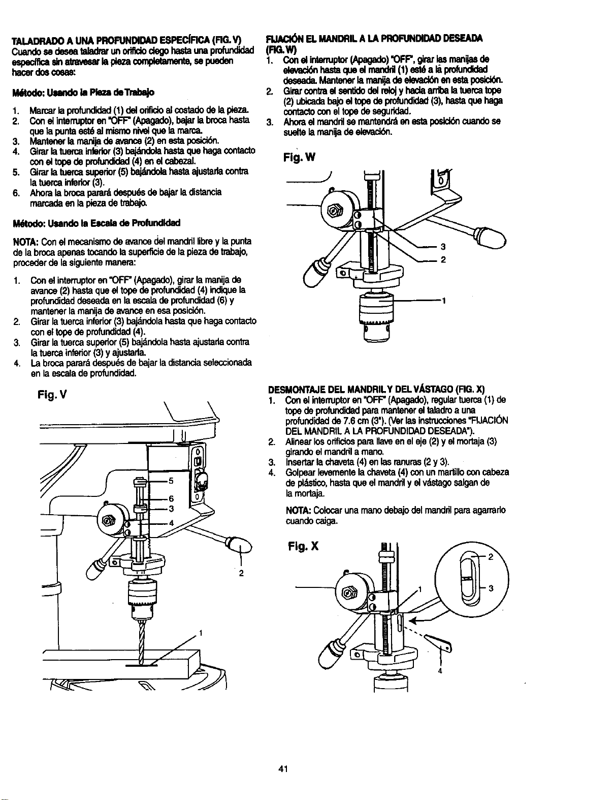
TALADRADOA UNAPROFUNDIDADESPECIFICA(RG.V)
Cuar_ se deseatalad_ unoritUodegohastaunaprofundk_
espemca¢na_=ar _pk3zacompk_amem,sep.eden
hacerdoscocas:
Uitodo: Uundo la Pie_ €leTrldx_
1, Marcarlaprofundidad(1)delorifidoelco6"tadodelapieza,
2. Conel intenuptoren"OFF"(Apegado),bajarlabrocahasta
quelapuntaest6el mismonivelquelamarca.
3. Mantenerlarnanijadeavarice(2)enestaposlo_.
4. Girarlatuercainfeder(3)bajatndelahastaquehagacontacto
coneltopedeprofundidad(4) enel cabezaL
5. Girarlatuercasuperior(5)bajdndolahastaajustadacontra
latuercainferkx(3).
6. Ahoralabrocapararddespudsdebajarladistancia
marcadaenlapiezadetmbajo.
I_todo: Usanclob Es_b deProfundld_l
NOTA:Conelmecanismodeavancedelmandrillibrey lapunta
delabrocaapenastocandolasuperficiedelapiezadetrabajo,
procoderdelasiguientemanera:
1. Conelinterruptoren"OFF"(Apagado),girarlamanijade
avance(2) basraqueel topedeprofundidad(4)indiquela
profundidaddeseadaenlaescalade pmfundidad(6)y
mantenerlamanijade avanceenesaposick_n.
2. Girarlatuercainferior(3)bajdndolahastaquehagacontaclo
coneltopedeprofundidad(4).
3. Girarlatuercasuperior(5)_la hastaajustadacontra
latuercainferior(3)y ajustarla.
4. Labrocaperarddespu6sdebajarladistanciaselecoionada
enlaescaladeprofundidad.
Fig. V
RJACI(_I ELMANDRILALA PRO_DAD DESEADA
(FIG.W)
1. Cone|intenuptor(Apagade)"OFF",g_ar_ manijasde
devad_ basraqueelmanddl(1)est6a li prdundidad
deseade.Mantenerlamanfjadedevack_enestapodck_.
2. Girarcontrael serfddodelrelojy hadaarribalatuercatope
(2)ubicadabajoeltopedeprofundidad(3),hastaquehaga
contactoconeltopede seguridad.
3. Ahoraelmanddlsemantendr,_enestaposick_cuandese
sueltelamanijadeelevackSn.
Fig. W
2
DESMONTAJEDEL MANDRILYDELV/_STAGO(FIG.X)
1. Conel intenuptoren"OFF"(Apegado),regulartuerca(1)de
topedeprofundidadperamantenerelteladroa una
profundidadde 7.6cm(3').(Verlasinstrucciones"FIJACK_
DELMANDRILA LAPROFUNDIDADDESEADA'),
2. Alinearlosorificiosparanaveeneleje(2)y elmortaja(3)
girandoelmandrila memo.
_. Insertarlachaveta(4)enlasranuras(2y 3).
• Golpearlevementelachaveta(4)conunma_lloconcabeza
depldsfico,hastaqueel mandrily elv"astagosalgande
larnortaja.
NOTA:Colocarunarnanodebajodelmandrilparaagarrado
coandocaJga.
Fig. X
2
1
4
41
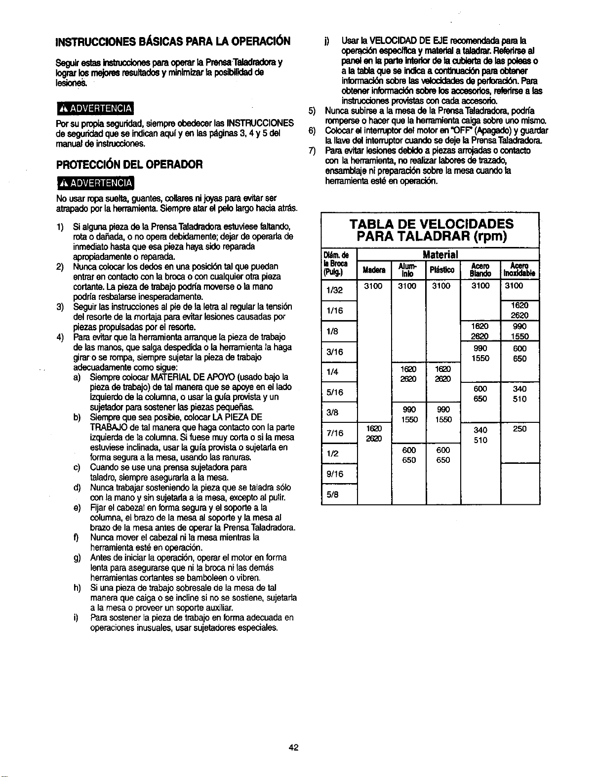
INSTRUCCIONES BASICAS PARA LA OPERACI6N
SegJirestasbs'm,,cdonesparaoperarla Prensa.Teladradoray
_ rnejomsresultadosy minlmizarla podbi_adde
Porsuproplasaguridad,siempreobedecerlasINSTRUCCIONES
deseguridadqueseindicanaqufyen lespdginas3,4y 5 del
manualdeinstrucdones.
PROTECCI6N DEL OPERADOR
R_r=1_=[=_l=Kffe]T.
Nousarropasuelta,guante_cdlaresnijoyasparaevitarser
atrapadoporla herramienta.Slampreafarelpstolargohaciaatrds.
1)
2)
3)
4)
$i algunapiezadela PrensaTeladradoraestuviesefaltando,
rotaoda_ada,o nooperadebidamente;dejardeoperarlade
inmediatobasraque esapiezahayasidereparada
apropiadamenteoreparada.
Noncacolocarlosdedosenunaposici6ntelque pusdan
entrarencontactoconlabrooaoconcualquierotrapieza
cortante.Lapiezadetrabajopodriamoverseola mano
podn'aresbalarseinesperadamente.
Seguirlasinstruccionesalpiedela letraal regularlatensibn
delresortede lamortajaparaevitarlesionescausadaspor
piezaspropulsadasporel resorte.
Parae_tarquela herramientaarranquela piezadetrabajo
de lasmanos,que salgadespedideo la herramientala haga
giraro serompa,siempresujetarla piezadetrabajo
adecuadamentecomosigue:
a) SiemprecolocarMATERIALDEAPOYO(usadobajola
piezade tmbajo)detalmaneraqueseapse enellade
izquierdodelacolumna,o usarla gufaprovistayun
sujetadorparasostenerlaspiezaspequeSas.
b) Siemprequeseaposible,colocarLAPIEZADE
TRABAJOdetalmaneraquehagacontactoconlaparte
izquierdadelacolumna.Sifuesemuycortaosila mesa
estuvieseinclinada,usarla guiaprovistaosujetarlaen
formaseguraa lamesa,usandolasranuras.
c) Cuandosauseunaprensasujetadorapara
taladro,siempreasaguradaa la mesa.
d) Nuncatrabajarsosteniendolaplazaquesataladras61o
conla manoy sinsujetarlaa la mesa,excoptoalpulir.
e) Fijarelcabezatenformaseguray elsoportea la
columna,elbrazodelamesaalsoportey lamesaal
brazodelamesaantesde operarlaPrensaTaladradora.
f) Nuncamoverelcabezalnila mesamientrasla
herramientaest_enoperacion.
g) Antesdeiniciarlaoperaci6n,operarelmotorenforma
lentaparaasegurarseque nilabrocanilesdem_.s
herramientascortantesse bamboleenovibran.
h) Siunapiezadetrabajosobresalede lamesadetal
maneraquecaigao seinclinesinosesostiene,sujetarla
a lamesao proveerunsoporteauxiliar.
i) Farasostenerlapiezadetrabajoenformaadecuadeen
operacionesinusuales,usarsujetadoresespeciales.
5)
6)
7)
j) Usarla VELOClDADDEEJErecomendadeparala
opemddnespedflcay materiala teladrar.Refedrseel
panelenI==parteInteriordetambierladelaspoleeso
a la tablaqueseindlcaa conUnuack_nparaobtener
informac_ sobrelasveloddedesdeperlomci_.Para
obtenerinformaci_ sobre Im accesodm, relerirsea las
in_nes provistasconcade accesodo.
Nuncasubirsea lamesade la PrensaTeladradora,podrfa
romperseohacerquelaherramientacaigasobreunomismo.
Colocarelintenuptordelmotoren"OFF"(Apagado)y guardar
la IlavedelinternJptorcuandosedejela PrensaTeladradora.
Paraevitarlesionesdebldea piezasarrojadasocontacto
conlaherramienta,norealizarlaboresdetrazado,
ensamblajeni prepamd6nsobrelamesacuandola
herramientaest6enoperaci6n.
TABLA DE VELOCIDADES
PARA TALADRAR (rpm)
_tm.de Material
;laBroca Alum- Pl_stico Acero Acero
i(Pulg.) Madera ink) BlandoInoxfdable
1/32 3100 3100 3100 3100 _3100
1/16
1620
118
262O
3/16 990
1550
1/4 16_0 16_0
262O 262O
5/16 600
65O
3/8 990 990
1550 1550
1620 340
7/16
2_0 510
1/2 600 6OO
650 650
1620
2_0
9_
1550
6_
6_
34O
510
25O
9/16
5/8
42
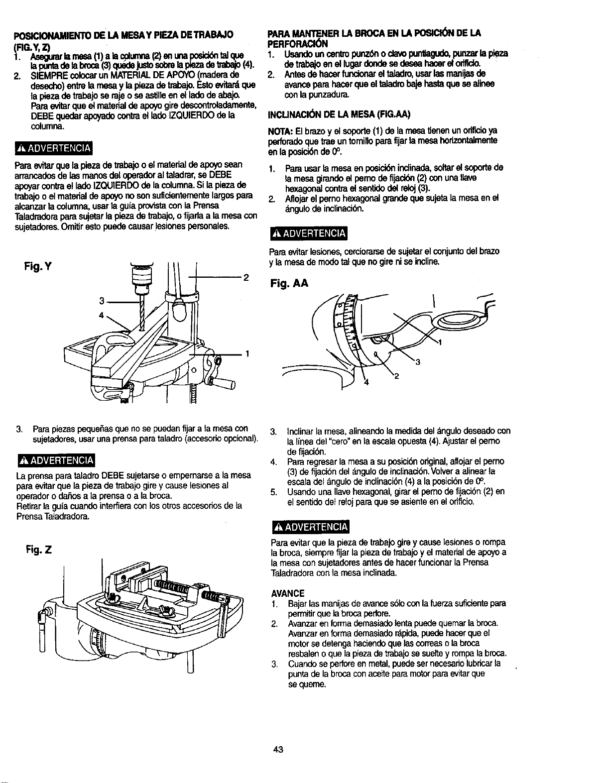
POSICIONAMIENTODELA MESAYPIEZADETRABAJO
(Rr-Y, Z)
1. Asagulark m',==a(1)a lacplurnna(2)an unaposidd_talqoe
lapuntadelabrcoa(3)quedejustosobrelaplezadetrabajo(4).
2. SIEMPREcolocarunMATERIALDEAPOYO(maderade
desecho)eff_relamesay lapiezadetrabajo.Estoevitardque
la piezadetrabajoserajeoseestflleenelladodeabaj_
Paraevitarqueetmaterialdeapoyogiredescontroladamente,
DEBEqu6daral_tado contraetladoIZQUIERDOdela
columna.
Paraevftarquefapiezadetrabajoo efmatertaldealx_ sean
arrancadosdelasmanosdeloperadoraltaladrar,se DEBE
apoyarcontraelladoIZQUIERDOdelacolumna.Silapiezade
trabajooelmatedaldeapoyonosonsuficienternentelargospara
alcanzarlacolumna,usartagu(aprovistaconlaPransa
Taladradoraparasujetarlapiezadetrabajo,ofijarlaa lamesacon
sujetadores.Omitirestopuedecausarlesionespersonales.
PARAMANTENERI.ABROCAENLAPOSICl6NDELA
PERFORACl6N
1. Usandoancentropunz6nodavopunliagudo,punzarlapieza
detrabajoenellugardondesedeseahacerelod_do.
2. Antesdehacerfuncionareltaladro,usarlasmanijasde
avanceparahacerqueeltaladrobajehastaquesaalinee
conlapunzadura.
INCUNACl0NDELA MESA(RG.AA)
NOTA: Elbrazo y el soporte(1) de la mesatJanenun oriflcioya
perfomdoque tree untomilloparefijarlamesa hofizontalmente
en laposici6nde 0°.
1. Parausarlamesaanposici6nindinad_coltarelsoportede
la mesagirandoelpemodefljaci_ (2)conuna,ave
hexsgon_contmelsantklodelreloj(3).
2. Aflojarelpemohexagonalgrandequesujetalamesaanel
_ngulodeinclinaci6n.
Pt__
Fig. Y
3 2 Fig. AA
c
Paraevitarlesiones,cemiorarsedesujetarelconjuntodelbrazo
y lamesademodotalquenogireniseincline.
3. Para piezas pequefias que nose puedan fijar a lamesa con
sujetadores, usar unaprensa para taladro (accesorio opcional).
LaprensaparataladroDEBEsujetarseo empemarseala mesa
paraevitarquelapiezade tmbaiogirey causelesionesal
operadorodafiosa la prensao a la broca.
Retirarla guiacuandointeffieraconlosotrosaccesofiosde la
PrensaTaladmdora.
3. Inclinarlamesa,alineandola medidadel_,ngulodeseadocon
laIfneadel"cero"enla escalaopuesta(4).Ajustarel pemo
de fijaciSn.
4. Pararegresarlamesaasuposicibnoriginal,aflojarelperno
(3) defijacibndel_mgulode inclinaci6n.Vo_veraalinearla
escaladelangulodeindinacibn(4)a laposicibnde0°.
5. UsandounaIlavehexagonal,girarelpemodefijacibn(2)en
elsentidodelrelojparaqueseasienteenelodflcio.
Fig. Z
Paraevitarquela piezade trabajogireycauselesioneso tampa
la bresa,siemprefijarla piezadetrabajoyelmaterialde apoyoa
la mesaconsujetadoresantesde hacerfuncionarla Prensa
Taladradoraconla mesaindinada.
AVANCE
1. Bajarlasmanijesdeavarices61oconlafuerzasuficientepara
permitirquelabrocaperlore.
2. Avanzarenformademasiadolentapuedequemarla broca.
Avanzarenformademesiado_koida,puedehacerqueel
motorsadetengahaciendoquelascorreaso labroca
resbaleno quelapiezadetrabajosasueltey rompalabresa.
3. Cuandoseperforeenmetal,puedesetnesesariolubricarla
puntade labrcoaconaceiteparamotorparaevitarque
sequeme.
43
MANTENIMIENTO DE LA PRENSA
TALADRADORA
Por supropiaseguddadcolocarel interruptorenla posicibn
"OFF" (Apagado)y desconectarelenchufedeltomacorriente
antesdedademantenimientoolubdcarlaPrensaTaiadmdora.
Eliminarconfrecuenciaelpolvoquesa acumuladentrodelmotor
sopl_ndoleairecon uncompresoro aspir_dolo.
Laaplicaci6ndeunacapadeceraautomotrizenpastaa lamesa
y a lacoLumnaayudar_ta mantenerlassuperficieslimpias.
Paraevitarlosdesgosdechoqueel6ctdcooincendio,siel
cordbneli.._,'tdcoestuviesegastadoo cortado,reparadoo
cambiarlode inmediato.
LUBRICACI( N
Todosloscojinetesdebolasdela PrensaTaladradoravienen
rellenosdegrasadesdelaf_brica.Norequierenlubrisaci6n
adicional.
Lubdcarperibdicamentelosengranajesy lacremallera,el
mecanismodeelevacibnde lamesa,elejedeltaladroy las
mandfbulasdesumortaja.
44
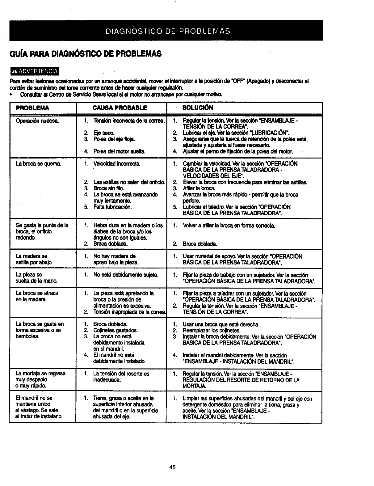
GUfAPARADIAGN( )STICODEPROBLEMAS
PareeviWIRionesocaslonadupotunmnmqueacdd_tal, moverelIntem¢_ alaposld_ de'OFF"(_) y _ _
cord_ desumlnls_delton_corrientem dehacercualqu_ regulaci6n,
• ConsultaralCentredeSen_doSeamlocal_ elmolornoammcMepotcualqulermo_w
PROBLEMA SOLUCI6N
Operac_ nddo_
Labrocaseq.ern_
Se _mlala_r_ _ la
Regular.laten_ Vetlasecd6n"ENSAMBI._E-
TENSIONDELACORREA'.
Lubdcareleje.Vetlasecci6n"LUBRICAClON'.
Asegummequelatuercaderetenck_delapo_a est6
ajusu_eyNumdeeHuesenece_a_
Aiuetereli_no de,jeck_ delai_ea delmotor.
i
Cambiarlavelocidad.Vetlasecck_n"OPERACIC_N
BJ_SICADELAPRENSATALADRADORA-
VELOCIDADESDELEJE'.
Elevarlabrocaoonfrecuendaparaeliminarlasaslglas.
Afllarlabroca.
Avanzarlabrocam_ r'apido- pem_itirquelabroca
perfom
LubdcareltaladroVerlasecctdn'OPERACION
BASICADELAPRENSATALADRADORA'.
Volvera afilarla brocaenformacorrecta.
1,
2.
3.
4.
1.
2.
3.
4.
5.
1.
2.
1.
1.
1.
2.
1.
2.
3.
4.
1.
Brocadoblada.
CAUSA PROBABLE
Tensk_incon'ectadelacorrea. 1.
Ejeee_. 2.
P_a_ _,oi_ 3.
Poleadelmotorsuelta. 4.
Velocidadincorrect_ 1.
Lasas_dllasnosalendelorifido. 2.
Brocasinfilo. 3.
Labrocasees_ avanzando 4.
muylefltamente.
Faitalubricack_. 5
HebradumenlamademoIo_ 1.
dlabesdelabrocay/olos
_gulosnosoniguales.
Brocadob_ 2.
Nohaymaderade I.
apoyobajo__za.
Noestddebidamentesujeta. 1.
Lapiezaest_apretandola 1.
brocao lapresi6nde
alimentaci_ese_cesiva. 2.
Tensi_inapropiadadelaconea
Brocadoblada. 1.
Cojinetesgastados. 2.
Labrocanoestd 3.
debidamenteinstalada
enetmanddl.
Elmanddlnoestd 4.
debidamenteinstalado.
Latensi6ndetresortees 1.
inadecuada.
Tierra,grasaoaceiteen la 1.
superfideinteriorahusada
delmandriloenlasuper6de
ahusadadeleje.
Lamaderase Usarmaterialdeapoyo.Verlaseccidn"OPERACION
asl_llaporabajo BASICADELAPRENSATALADRADORA'
Lapiezase Rjarlapieza,de.'qzzbajoconunsujetador.Verlasecck_
sueltadela mano. OPERACIONBASICADELAPRENSATALADRADORA'.
Labrocaseatraca Rjarla_ a ta;_,L_lmrconunsu'.lel_or.Verlaseccibn
enla madem. "OPERAClONBASICADELA PRENSATALADRADORA'.
Regula[,latensi6n.Verlasecck_'ENSAMBLAJE-
TENSIONDELA CORREA'.
Labrocasegastaen
foffnaexcesivao se
bambolea.
Usarunabrocaqueest6derecha.
Reemp_zzarlosmjinetes,
Instalarlabrocadebidamente.Vetlasecc_n"OPERACI(_N
BASICADELAPRENSATALADRADORA'.
Instalarelrnanddldebidamente.Verlasecck_n
'ENSAMBLAJE- INSTALACI(_NDELMANDRIL'.
Lamortajase regresa Regularlatensk_.Verlasec_ "ENSAMBLAJE-
muydespado REGULACIONDELRESORTEDERETORNODELA
o muyr_..pido. MORTAJA.
Elmanddlnose 1. Limpiarlassuperficiesahusadasdelmanddly d_ ejecon
man6eneunido detergentedorn6stJcopareeliminarlatierra,grasay
alvSsta9o.Sesale aceite.Vetlasecck_n"ENSAMBLAJE-
altratardeinstalado. INSTALACIC_)NDELMANDRIL'.
45
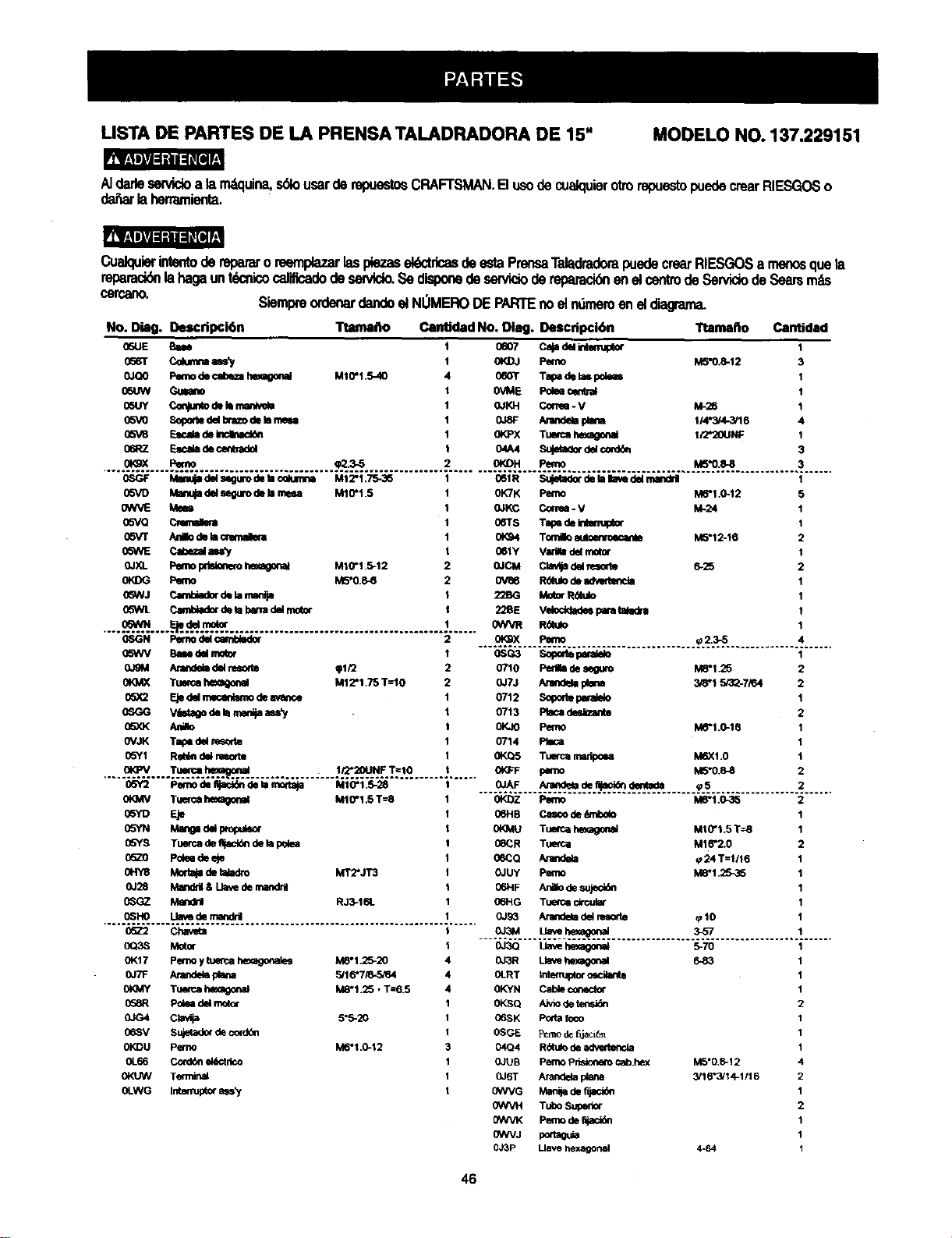
LISTA DE PARTES DE LA PRENSA TALADRADORA DE 15" MODELO NO. 137.229151
AIdarlesewicioa la m_quina,s_o usarderepuestosCRAFTSMAN.B usodecuak:luierotrorepuestopuedecrearRIESGOSo
da_arlaherramienta.
Cualquierinte_oderepararoreemplazarlaspiezasel6ctdcasdeestaPrensaTaladradorapuedecrearRIESGOSa rne/x_quela
repamck_lahagaunt_cnicocalificadodesen/Ido.Sedisponedeservicioderepamcidnenel_ _ _ _ _ m_
cercano. SiempreordenardandoelNOMERODEPARTEnoelnOmeroeneld_
No. Diag. Descripci6n Ttamaflo Canbdad No. Diag. Descdpci6n
06UE E_m
0_r Cokm_==.s_/
0JO0 Pemode¢al0ezahexagonal
05UW GLeam
05UY Cequmode_ man_ve_
05VO SopohedelbrazodeIsm
05V8 _ deIncinad_
06RZ FJN_adeceqbadel
M1_1.5-40
Ttamaho Cantidad
oeo7 caja d_ _tmup_ 1
0KDJ Pef_o M5"0.8-12 3
060T TalPade bmpdems 1
0VME Poleecentral t
OJKH Corree - V M-26 1
0JSF Arar_ F_ana 114"N4-3/16 4
0_3=X Tuwca hexagonal I/2*20UNF 1
04A4 Sujeta_r del cord_ 3
ORgX Pemo _2.3-5 OI_H Pemo M5"0.8-8 3
0SGF IV_ del s6guro de lac(_mna MI 2"1.75-35 061R Sujetader de faIlave del ma_d_ 1
05VD Ma_ del segurode kl meu M10"1.5 0K7K Peso M6"1.0-12 5
_NVE Meal 0JKC Collru - V M-24 1
05VQ Cmmalma 06Ts Tal_ deIntm_otor 1
05VT AnBodehlm 0KS4 Tomao N M5"12-16 2
05WE Cabl_al al_y 06ty Vldla d_ motor 1
0JXL I_mo pdstonemhexagonal MI0"t.5-12 0JCM Clavqa d_ resor_ 625 2
0_I)G Pemo M5"0.8_ 0V86 R6ttdodem 1
05WJ CamUador d_ _-m 22BG Motor RUado I
05WL Canl_ader de ta bana del r_tor 228E Vek)ddade_ para ta_dra t
...._....._..._....m_..................................................... _ R_o 1
0SGN Pemo del carffolador
05WV Based_ mo_ 0SG3 Sopode perm_
0J_M Arandeb del reso_te _t/2 0710 Pedla de seguro M8"1.25
0K]_K TLWCa heo_onal M12"1.75 1"=10 0JTJ Arandela plana 348"15r32-7_4
05_2 Ejedel mecanlsmo de avar_e 0712 S_ paral_o
0SGG V_ de I_ marf_aass_ 0713 F_a_l desl_ante
05XK AJr_o _ Pefno M6"1.0-16
OVJK Tap_ del resorle 0714 PIIca
05Y1 Ret_n del nmorte OKQ5 Tuerca manlx_a M6X1.0
O_X Pemo
............................................ ._..z._............... 4......
1
2
.... ...o_........T.....=._ ............. ;.__.I_N._..T==!0.............
(:6Y2 Pemodeqact_nde_amodaja M10"1.5-28
0t_qV Tuemahexagor,al M10"1.5T--8
0SYD Eje
0SYN Ma_gad_ Wop_,_o(
05YS Tu_fcadefljacldndelap_ea
O57-O I='o_edeeje
0HY8 Morta_det_adro MT2"JT3
O.128 Manddl& Lla_ dernandfig
0_GZ _ RJ3-t61.
0_HO Llavedemandril
0KFF pemo M5"0.8-8
._.OJ.AF...._._._._ ......._.S.........................
0K_Z Pemo M6"1.0-3_
06HB Casco de_ni0olo
0KMU Tue_c_ h_agor_l M10"1.5 T=8
08CR Tue_ca M16"2.0
06CQ Arandela (724 T=1/16
OJUY Pemo M8"1.25-35
06HF Ani_ode sujec_n
06HG Tt_e_ circular
0J93 Arandela de_msode _10
o_z c_m ___.%_......._ ................. .._...........................
0Q3S Motor
01<17 Pe_noy tuef_a he_agonales M8"1.25-20
OJ7F Arandegaplana 5/16"7/8-,5_4
0tOAY Tu_ca h_ M8"I .25 • T=6.5
058R Polea del motor
0JG4 _ 5"5-20
06SV Sujetadorde cordon
0KDU Pemo M6*t _-12
0L66 Con/_n ekk:tdco
0KUW Terminal
0LWG Inte_ asset
0J3Q _ hexagonal 5-70
0J3R Llave hexagonal
04J_T tnte_uptor oscilante
0KYN Cable conect_
0KSQ Aivio de _
06SK Poda foco
0SGE P_modefi_aci6n
04Q4 R_ulo de advede_<',ia
OJUB Pemo P_ cab.he0( M5"0.8-12
0J6T Arandelaplana 3/16"3/14-1/16
0WVG Mani_ de ft_
(_VVH Tubo Superior
OWVK Pernode r_ac_n
0WVJ po_taguia
0J3P Llave hexagonal 4-64
46

LISTA DE PA_ES DE _ PRENSATA_DRADORA DE 15" MODELO NO. 137.229151
i
\
I
\
L
/
i
_R
r
47

Your Home
For repair-in your home-of all major brand appliances,
lawn and garden equipment, or heating and cooling systems,
no matter who made it, no matter who sold it!
For the replacement parts, accessories and
Operator's Manuals that you need to do-it-yourself.
For Sears professional installation of home appliances
and items like garage door openers and water heaters.
1-800-4-MY-HOME ® (1-800-469-4663)
Call anytime, day or night (U.S.A. and Canada)
www,sears.com www.sears.ca
Our Home
For repair of carry-in items like vacuums, lawn equipment,
and electronics, call or go on-line for the location of your nearest
Sears Parts & Repair Center.
1-800-488-1222
Callanytime,dayor night(U.S.A.only)
www.sears.com
To purchase a protection agreement (U.S.A)
or maintenance agreement (Canada) on a product serviced by Sears:
1-800-827-6665 (u.s.A.) 1-800-361-6665 (Canada)
Para pedir servicio de reparacibn
a domicilio, y para ordenar piezas:
1-888-SU-HOGAR s"
(1-888-784-6427)
Au Canada pour service en franctais:
1-800"LE-FOYER "c
(1-800-533-6937)
www.sears.ca
6EAR6
® Registered Trademark I TM Trademark / SMService Mark of Sears, Roebuck and CO
® Marca Registrada / TMMarca de Fdbrica / sMMarca de Servicio de Sears, Roebuck and Co
uc Marque de commerce / MOMarque d_pos_e de Sears, Roebuck and Co © Sears, Roebuc_ and Co