Loading ...
Loading ...
Loading ...
Part number 550-100-400/0119
79
®
Series 4
gas-fired water boiler — Boiler Manual
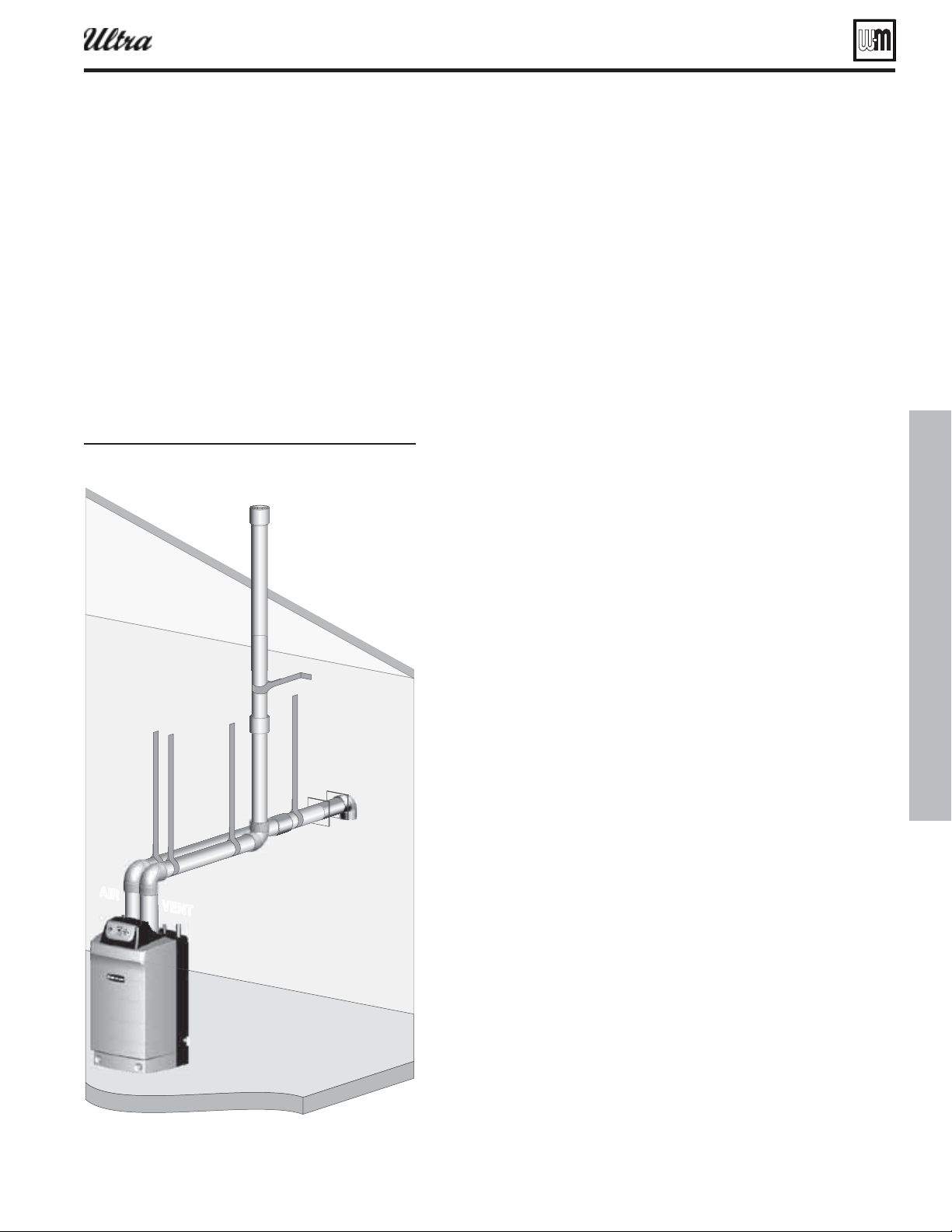
DIRECT VENT: Vertical vent / sidewall air
Determine location
1. Locate the vent termination using the following guidelines:
2. The vent piping must terminate in an up-turned coupling as shown
in Figure 92, page 80 . The top of the coupling must be at least 1 foot
above the air intake.
3. You must consider the surroundings when terminating the vent and air:
a. Position the vent termination where vapors will not damage nearby
shrubs, plants or air conditioning equipment or be objectionable.
b. The fl ue products will form a noticeable plume as they condense in
cold air. Avoid areas where the plume could obstruct window views.
c. Prevailing winds could cause freezing of condensate and water/ice
buildup where fl ue products impinge on building surfaces or plants.
d. Avoid possibility of accidental contact of fl ue products with people
or pets.
e. Do not locate the terminations where wind eddies could affect
performance or cause recirculation into building or appliance air
intakes, such as inside building corners, near adjacent buildings
or surfaces, window wells, stairwells, alcoves, courtyards or other
recessed areas.
f. Do not terminate above any door or window. Condensate can freeze,
causing ice formations.
g. Locate or guard vent to prevent condensate damage to exterior
fi nishes.
4. Maintain clearances to vent termination as given below:
a. Vent must terminate:
At least 6 feet from adjacent walls.
No closer than 5 feet below roof overhang.
At least 3 feet above any forced air intake within 10 feet.
No closer than 12 inches below or horizontally from any door
or window or any other gravity air inlet.
b. Do not terminate vent closer than 4 feet horizontally from any
electric meter, gas meter, regulator, relief valve or other equip-
ment. Never terminate above or below any of these within 4 feet
horizontally.
5. Locate terminations so they are not likely to be damaged by foreign ob-
jects, such as stones or balls, or subject to buildup of leaves or sediment.
6. Do not connect any other appliance to the vent pipe. Do not connect
multiple boilers to a common vent pipe.
Prepare roof penetrations
1. Vent pipe penetration:
a. Cut a hole for the vent pipe. For either combustible or noncombus-
tible construction, size the vent pipe hole at least 0.4” larger than
the vent pipe diameter:
2¾” hole for 2”
4” hole for 3”
5” hole for 4”
b. Insert a galvanized metal thimble in the vent pipe hole.
2. Follow all local codes for isolation of vent pipe when passing through
fl oors, ceilings and roofs.
3. Provide fl ashing and sealing boots sized for the vent pipe and air pipe.
Allowable vent/air pipe materials
1. Use only the materials listed in Figure 13, page 19 .
2. Purchase bird screens for vent and air termina-
tions separately. See the parts list at the end of this
manual.
Maximum piping lengths
1. Locate the terminations such that the total air pip-
ing and vent piping from the boiler to the termina-
tion will not exceed the maximum length given in
Figure 12, page 18 .
2. Maximum lengths listed in Figure 12, page 18 allow
for 1 elbow in the air piping and 1 elbow in the vent
piping. Additional elbows required a reduction in
maximum length as explained in the table notes.
Figure 91
674CX
7&/5
"*3
Loading ...
Loading ...
Loading ...