Loading ...
Loading ...
Loading ...
Part number 550-100-400/0119
71
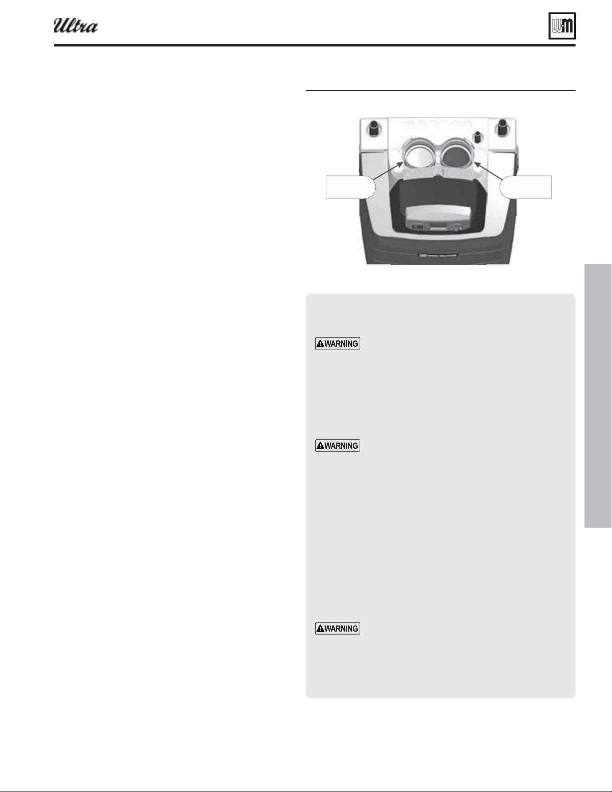
Install vent/air piping — boiler to W-M termination
Figure 77 Boiler ent and air connections
"JSQJQF
DPOOFDUPS
7FOUQJQF
DPOOFDUPS
6
Inserting/securing vent or air pipe into
boiler connectors
AL29-4C vent pipe — If using AL29-4C stainless
vent pipe, you must install a PVC-to-vent pipe
adapter at the boiler vent connection (and at the
termination if using the Weil-McLain plate or the
concentric termination). Use only the adapter made
by the vent pipe manufacturer.
1. PVC/ABS pipe — Clean and chamfer insertion end of pipe.
Deburr inside of insertion end. Clean and deburr inside and
outside of other end of pipe.
The pipe end must be smooth and chamfered to
prevent possible damage to sealing gasket in vent
or air pipe adapter. Failure to comply could result
in leakage, causing possible severe personal injury
or death.
2. Inspect vent or air adapter (above) — verify no obstructions
or foreign objects inside.
3. Loosen clamp screw.
4. Measure 3½ inches from end of pipe and make a mark with
felt-tip pen.
5. Loosen adapter clamp screw.
6. Apply small amount of silicon grease to end of pipe to ease
insertion.
7. Insert pipe into adapter.
8. Slide pipe down until the 3½-inch mark is reached.
Do not apply excessive force or bend the adapter
or fl ue/air pipe when inserting. The adapter or seal
could be damaged.
9. Secure vent or air pipe by tightening the adapter clamp se-
curely. Do not overtighten. The seal is accomplished with the
internal gasket. The clamp is only to hold the pipe in place.
®
Series 4
gas-fired water boiler — Boiler Manual
Complete termination preparation
1. Install vent and air terminations before proceeding.
See previous pages for instructions.
Installing vent and air piping
1. For reference in the following, see previous pages.
2. Work from the boiler to vent or air termination. Do not
exceed the lengths given in the previous pages for either
the air or vent piping.
a. As shown in the maximum length tables, the
Ultra-80 or Ultra-105 may be installed with either
2-inch or 3-inch vent and air piping.
b. As shown in the maximum length tables, the
Ultra-230 may be installed with either 3-inch or
4-inch vent and air piping.
c. You must install appropriate pipe reducers, where
required, at both the boiler and at the termination
assembly.
3. See Figure 77 for attaching vent and air pipes at the
boiler.
4. Cut pipe to required lengths.
5. Deburr inside and outside of pipe ends.
6. Chamfer outside of each pipe end to ensure even cement
distribution when joining.
7. Clean all pipe ends and fi ttings. Dry thoroughly.
8. Dry assemble entire vent or air piping to ensure proper
fi t before assembling any joint.
9. For each joint:
a. Handle fi ttings and pipes carefully to prevent con-
tamination of surfaces.
b. Apply primer liberally to both joint surfaces — pipe
end and fi tting socket.
c. While primer is still damp, lightly apply approved
cement to both surfaces in a uniform coating.
d. Apply a second coat to both surfaces. Avoid using
too much cement on sockets to prevent cement
buildup inside.
e. With cement still wet, insert pipe into fi tting, twist-
ing ¼ turn. Make sure pipe is fully inserted.
f. Wipe excess cement from joint. Check joint to be
sure a smooth bead of cement shows around the
entire joint.
10. Install pipe supports as shown in Figure 76, page 70 .
11. Slope vent and air piping continuously toward boiler,
with at least 1/4 inch drop per foot of run. Do not allow
sags at any point.
12. Maintain minimum clearance of
3/16 inch between vent
pipe and any combustible wall or material.
13. Seal wall or fl oor penetration openings following local
code requirements.
Loading ...
Loading ...
Loading ...