Boiler Manual
Gas-fi red water boilers – Series 4
Featuring
Flexibility
®
®
Part number 550-100-400/0119
This manual must only be used by a qualifi ed heating installer/service technician. Read all instructions, including this manual and
all other information shipped with the boiler, before installing. Perform steps in the order given. Failure to comply could result in
severe personal injury, death or substantial property damage.
®
Contents Ultra at-a-glance
(see page 44 and page 46 for details of all models)
The following defi ned terms are used throughout this manual to bring
attention to the presence of hazards of various risk levels or to important
information concerning the life of the product.
Indicates presence of hazards that will cause severe
personal injury, death or substantial property
damage.
Indicates presence of hazards that can cause severe
personal injury, death or substantial property
damage.
Indicates presence of hazards that will or can cause
minor personal injury or property damage.
Indicates special instructions on installation,
operation or maintenance that are important but not
related to personal injury or property damage.
Hazard defi nitions
Part number 550-100-400/0119
2
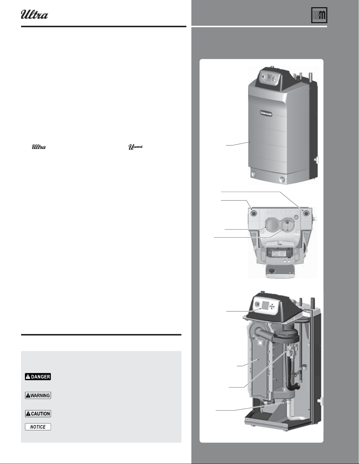
'SPOU
5PQ
DPOUSPMQBOFMTXVOHPQFO
*OUFSJPS
UZQJDBM
'SPOUEPPS
&MFDUSPOJDEJTQMBZ
CVUUPOT
4VQQMZ
3FUVSO
"JSJOUBLF
'MVF
"MVNJOVN
DPOEFOTJOH
IFBUFYDIBOHFS
(BTWBMWFCMPXFS
BOEWFOUVSJ
$POEFOTBUF
ESBJO
6
®
Series 4
GAS-FIRED WATER BOILER
aard de nitions Ultra at-a-lance . . . . . . . . . . . . . . 2
lease read efore proceedin . . . . . . . . . . . . . . . . . . 4
repare oiler location . . . . . . . . . . . . . . . . . . . . . . 5
repare oiler. . . . . . . . . . . . . . . . . . . . . . . . . . . 7
Install ater pipin . . . . . . . . . . . . . . . . . . . . . . . . 9
Usin ith eil-cLain AUA LUS ater heaters . . . . . . 14
entinair pipin eneral . . . . . . . . . . . . . . . . . . 16
Sideall entair termination Separate pipes . . . . . . . . . 20
DIRECT VENT . . . . . . . . . . . . . . . . . . . . . . . . . 25
Install condensate line . . . . . . . . . . . . . . . . . . . . . 27
as pipin . . . . . . . . . . . . . . . . . . . . . . . . . . . 29
ield irin asic sstem . . . . . . . . . . . . . . . . . . 30
U-Control operation and setup . . . . . . . . . . . . . . . . . 32
Startup ll the sstem . . . . . . . . . . . . . . . . . . . . 35
Startup nal checs . . . . . . . . . . . . . . . . . . . . . 37
Chec-outstartup eri cation. . . . . . . . . . . . . . . . . . 42
The
as- red ater oiler eaturin leiilit . 44
repare oiler conert for propane . . . . . . . . . . . . . 48
lacin oiler all-mountin option . . . . . . . . . . . . . 50
Install ater pipin adanced . . . . . . . . . . . . . . . . 52
irect-connected pipin . . . . . . . . . . . . . . . . . 56
ultiple oiler installations . . . . . . . . . . . . . . . . . . . 58
entinair pipin assachusetts installations . . . . . . . 65
entair pipin options . . . . . . . . . . . . . . . . . . . . 66
Sideall entair termination eil-cLain cap . . . . . . . . 67
Sideall entair termination or concentric. . . . . . . . 72
ertical entair termination or concentric. . . . . . . . 75
Concentric entair termination asseml. . . . . . . . . . . . 78
ICT NT ertical ent sideall air . . . . . . . . . . . 79
Install entair pipin oiler to termination . . . . . . . . . . 82
ICT AUST entin eneral. . . . . . . . . . . . . 83
ICT AUST Boiler room air openins . . . . . . . . 84
ICT AUST Sideall . . . . . . . . . . . . . . . . 86
ICT AUST ertical . . . . . . . . . . . . . . . . . 89
Install ent from oiler to termination . . . . . . . . . . . . 91
as pipin siin as lines . . . . . . . . . . . . . . . . . 93
ield irin adanced . . . . . . . . . . . . . . . . . . . . 94
U-Control operation and setup adanced . . . . . . . . . . 99
Annual startup and eneral maintenance. . . . . . . . . . . . 108
Annual startup . . . . . . . . . . . . . . . . . . . . . . . . . 109
Trouleshootin. . . . . . . . . . . . . . . . . . . . . . . . . 115
aintenance . . . . . . . . . . . . . . . . . . . . . . . . . . 125
eplacement parts . . . . . . . . . . . . . . . . . . . . . . . 128
imensions . . . . . . . . . . . . . . . . . . . . . . . . . . . 136
atins Ultra Series oilers . . . . . . . . . . . . . . . . 137
Installation and Serice Certi cate . . . . . . . . . . . . . . . 140

MAINTENANCE &
SPECIFICATIONS
(Pages 108–140)
This section covers maintenance require-
ments for all boilers, repair parts lists, boiler
dimensions and specications.
BASIC INSTALLATION
Quick view . . .
Pages
Procedure
4
Please read before proceeding
•Readsafetyinformationbeforeproceeding
5–6
Prepare boiler location
•Clearances,oorandfoundation
•Airopeningstoroomforventilation
7–8
Prepare boiler
•Makesurevent/airpipingcanbeconnected
•Removefromcrate
•Convertforpropane,ifrequired
•Hydrostatictest
•Placeboilerinposition
9–15
Install water piping
•Installboilertrimandnearboilerpiping
•Completesystempipingandconnections
16
Appliances left on an existing vent system
•Forappliancesremainingonaventsystemaerold
boilerisdisconnected—verifythattheventsystem
worksforremainingappliances
16-26
Vent/air piping
•Locateairintakepipingtopreventcontaminantsfrom
enteringboiler
•Installvent/airtermination
•Installventandairpipingusingacceptablematerials
27–28
Install condensate piping
•Connectcondensatehose
•Installcondensatepumpandlter,ifrequired
29
Gas piping
•Verifygaspipesize
•Connectboilertogasline
30-31
Field wiring
•Connectwiringtoboilerandcomponents
32–34
U-Control operation and setup
•U-Controloperationandsetupinformation
35–42
Start-up
•Cleansystem,thenll;addinhibitor
•Verifywaterchemistry
•Purgeairfromsystem
•Performnalchecks
•Startandoperateboiler
•Performnalvericationtests
•FilloutInstallationandServiceCerticate
BASIC INSTALLATION
ADVANCED INSTALLATION
(Pages 44–107)
Read and follow the instructions in the
BASIC INSTALLATION section rst. Then
use the ADVANCED section for additional
information.
This section covers multiple boiler systems
and additional system types not covered
under the BASIC section. It also includes
alternative vent/air piping methods, water and
gas pipe sizing guidelines and advanced,
detailed information on the U-Control.
Part number 550-100-400/0119
3
BASIC INSTALLATION
(Pages 3–42)
This section covers basic installation and
start-up for most applications. It is limited to
conventional systems and to sidewall vent/
air piping using the Weil-McLain termina-
tion cap.
For applications not covered in this sec-
tion, see the ADVANCED INSTALLATION
section.
Part number 550-100-400/0119
4
Please read before proceeding
Failure to adhere to the guidelines below can result in severe personal injury, death or substantial property damage.
When servicing boiler —
To avoid electric shock, disconnect all
electrical supplies to the boiler before
performing maintenance.
To avoid severe burns, allow boiler to
cool before performing maintenance.
This boiler contains ceramic fi ber and
fi berglass materials. Refer to the WARN-
ING and instructions on page 109 .
Do not block fl ow of combustion or
ventilation air to boiler.
Should overheating occur or gas supply
fail to shut off, do not turn off or discon-
nect electrical supply to pump. Instead,
shut off the gas supply at a location
external to the appliance.
DO NOT install combustion air intake
where there is a risk of combustion air
contamination.
A carbon monoxide detector that is
wired on the same electrical circuit as
the boiler is strongly recommended.
Provide surge protection in the boiler
power supply. This will reduce the pos-
sibility of damage to the boiler control.
Boiler water —
The Ultra heat exchanger is made of
aluminum, and requires that system pH
always be between 7.0 and 8.5 and water
chemistry be checked. Chemical treat-
ment may be necessary.
. See page 35 for details.
Thoroughly fl ush the system (
connecting boiler) to remove sediment.
The high-effi ciency heat exchanger can
be damaged by build-up or corrosion
due to sediment.
Do not use petroleum-based cleaning
or sealing compounds in boiler system.
Gaskets and seals in the system may be
damaged. This can result in substantial
property damage.
Continual fresh make-up water will
reduce boiler life. Mineral buildup in
eat exchanger reduces heat transfer,
overheats the aluminum heat exchanger,
and causes failure. Addition of oxygen
carried in by make-up water can cause
internal corrosion. Leaks in boiler or
piping must be repaired at once to
prevent make-up water. Use this boiler
ONLY in a closed-loop system.
Do not add cold water to a hot boiler.
Thermal shock can cause heat exchanger
to crack.
Freeze protection fl uids —
NEVER use automotive or standard
glycol antifreeze. Use only freeze-protec-
tion fl uids made for hydronic systems.
Use only freeze-protection fl uids recom-
mended in this manual (see page 35 ).
Follow all guidelines given by the anti-
freeze manufacturer. Thoroughly clean
and fl ush any replacement boiler system
that has used glycol before installing the
new Ultra boiler
Frozen Water Damage
Hazard
Residences or buildings that are unat-
tended in severely cold weather, boiler
system components failures, power out-
ages, or other electrical system failures
could result in frozen plumbing and water
damage in a matter of hours. For your
protection, take preventative actions such
as having a security system installed that
operates during power outages, senses low
temperature, and initiates an effective ac-
tion. Consult with your boiler contractor
or a home security agency.
If any part of a boiler, burner or its controls has
been sprayed with or submerged under water,
either partially or fully, DO NOT attempt to op-
erate the boiler until the boiler has been either
replaced or completely repaired, inspected, and
you are sure that the boiler and all components
are in good condition and fully reliable.
Otherwise, by operating this boiler, you will
cause a fi re or explosion hazard, and an electrical
shock hazard, leading to serious injury, death, or
substantial property damage. See the instructions
at right.
— The exposure of boiler components to
saltwater can have both immediate and long-term effects. While the
immediate effects of saltwater damage are similar to those of fresh-
water (shorting out of electrical components, washing out of critical
lubricants, etc.), the salt and other contaminants left behind can lead
to longer term issues after the water is gone due to the conductive
and corrosive nature of the salt residue. Therefore, Weil-McLain
equipment contaminated with saltwater or polluted water will no
longer be covered under warranty and should be replaced.
— If any or
came into contact with water, or was suspected to have come into
contact with water, replace the boiler with a new Weil-McLain boiler.
Commonwealth of
Massachusetts
When the boiler is installed within the Commonwealth of Massachusetts:
This product must be installed by a licensed plumber or gas fi tter.
If antifreeze is used, a reduced pressure back-fl ow preventer device shall be used.
Sidewall vent air installations — see instruction on page 65 .
— Read all instructions, including this
manual and all other information shipped with the
boiler, before installing. Perform steps in the order
given.
— This manual is for use only by a qualifi ed
heating installer/service technician. Refer to User’s
Information Manual for your reference.
— Have this boiler serviced/inspected by a
qualifi ed service technician, at least annually.
Failure to comply with the above could result in severe
personal injury, death or substantial property damage.
Write in the CP number in the space provided on
the Installation certifi cate on page 140 if not already
shown.
When calling or writing about the boiler— Please
have the boiler model number from the boiler rating
label and the CP number from the boiler jacket.
Consider piping and installation when determining
boiler location.
Any claims for damage or shortage in shipment
must be fi led immediately against the transportation
company by the consignee.
®
Series 4
gas-fired water boiler — Boiler Manual
Part number 550-100-400/0119
5
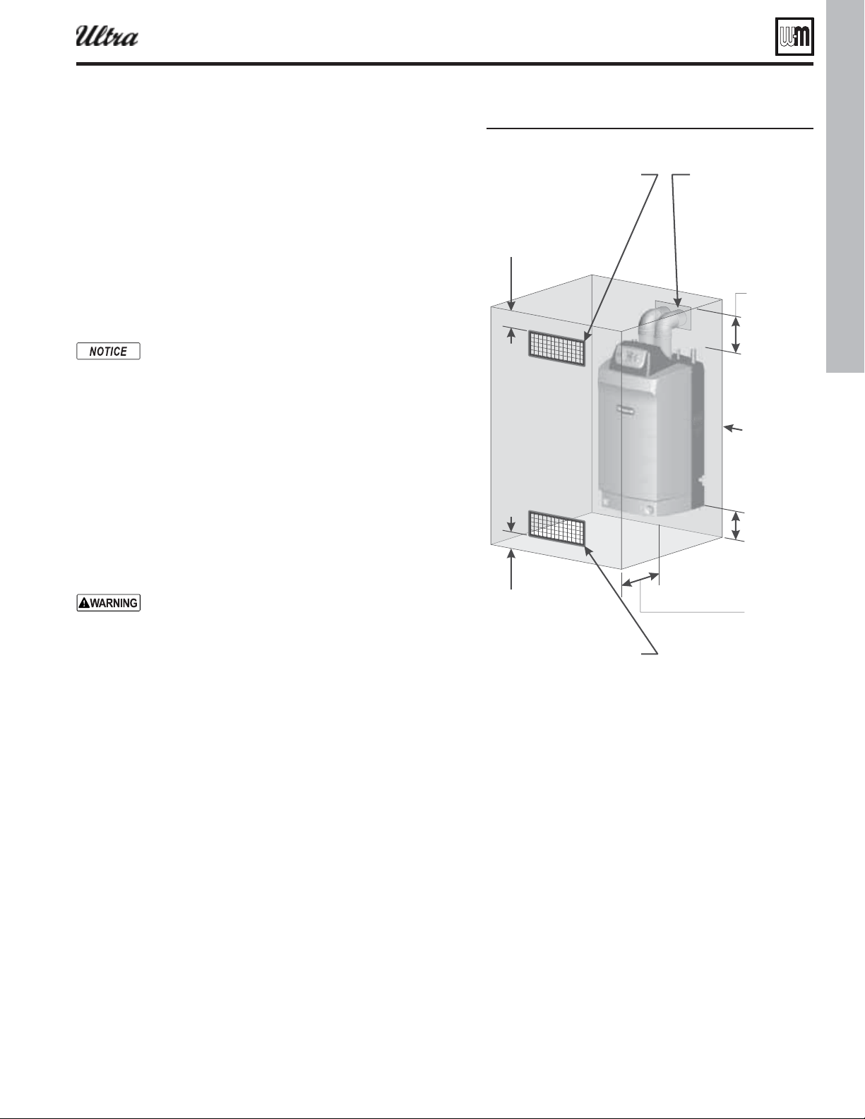
Figure 1Clearances reuired
Prepare boiler location
Installations must comply with:
Local, state, provincial, and national codes, laws, regulations and
ordinances.
National Fuel Gas Code, ANSI Z223.1 /NFPA 54 – latest edition.
Standard for Controls and Safety Devices for Automatically Fired
Boilers, ANSI/ASME CSD-1, when required.
National Electrical Code.
For Canada only: Natural Gas and Propane Installation Natural
Gas and Propane Installation
CAN/CSA
B149.1 or B149.2 Instal-
lation Code, CSA C22.1 Canadian Electrical Code Part 1 and any
local codes.
The Ultra boiler gas manifold and controls met safe
lighting and other performance criteria when boiler un-
derwent tests specifi ed in ANSI Z21.13 — latest edition.
Before locating the boiler, check:
1. Check for nearby connection to:
System water piping
Venting connections
Gas supply piping
Electrical power
Condensate drain
2. Check area around boiler. Remove any combustible materials,
gasoline and other fl ammable liquids.
Failure to keep boiler area clear and free of combustible
materials, gasoline and other fl ammable liquids and
vapors can result in severe personal injury, death or
substantial property damage.
3. The Ultra boiler must be installed so that gas control system com-
ponents are protected from dripping or spraying water or rain
during operation or service.
4. If new boiler will replace existing boiler, check for and correct
system problems, such as:
System leaks causing oxygen corrosion or heat exchanger cracks
from hard water deposits.
Incorrectly-sized expansion tank.
Lack of freeze protection in boiler water causing system and
boiler to freeze and leak.
Provide clearances:
Clearances from combustible materials
1. Hot water pipes — at least ½” from combustible materials.
2. Vent pipe — at least
3/16” from combustible materials.
3. See Figure 1 for other clearance minimums.
Clearances for service access
1. See Figure 1 for recommended service clearances. If you
do not provide minimum clearances shown, it might
not be possible to service the boiler without removing
it from the space.
Wall mounti ng option
1. Ultra boilers can be wall mounted (using special wall
mount kit) or fl oor mounted.
, either for service or
for clearance to combustible surfaces.
2. Boilers can be wall mounted ONLY if using the optional
wall-mount kit available from Weil-McLain. See page 50
for instructions.
PD[LPXPDERYH
IORRURIHQFORVXUH
PD[LPXPEHORZ
FHLOLQJRIHQFORVXUH
8
$LUYHQWLODWLRQRSHQLQJVZKHQ
UHTXLUHG²VHH³3URYLGHDLU
RSHQLQJVWRURRP´
723
6HUYLFH²
PLQ
&RPEXVWLEOH
VXUIDFHV²
òPLQ
5LJKW6,'(
6HUYLFHRU
FRPEXVWLEOH
VXUIDFHV²
PLQ
/HIW6,'(
6HUYLFH²
PLQ
&RPEXVWLEOH
VXUIDFHV²
òPLQ
%27720
6HUYLFH²
PLQ
&RPEXVWLEOH
VXUIDFHV²
PLQ
)/8(3,3(
&RPEXVWLEOHVXUIDFHV²
´PLQ²
2SHQLQJLQFRPEXVWLEOH
ZDOOIORRUFHLOLQJRUURRI
ODUJHUWKDQIOXHSLSH
GLDPHWHUILWWHGZLWK
JDOYDQL]HGVWHHOWKLPEOH
&RPEXVWLEOH
VXUIDFHV²
òPLQ
)5217
6HUYLFH²
PLQ
$LUYHQWLODWLRQRSHQLQJV
VHHLQVWUXFWLRQVLQWKLVPDQXDO
®
Series 4
gas-fired water boiler — Boiler Manual

Part number 550-100-400/0119
6
Prepare boiler location (continued)
Flooring and foundation
Flooring
The Ultra boiler is approved for installation on combustible fl ooring,
but must never be installed on carpeting.
Do not install boiler on carpeting even if foundation is
used. Fire can result, causing severe personal injury, death
or substantial property damage.
Foundation
1. Provide a solid foundation pad, at least 2 inches above the fl oor, if
any of the following is true:
fl oor can become fl ooded.
the fl oor is dirt, sand, gravel or other loose material.
the boiler mounting area is severely uneven or sloped.
2. The minimum foundation size is:
Ultra-80 to -230: 24 inches wide x 20 inches deep.
Ultra-299/310 to -399: 24 inches wide x 23 inches deep.
3. Foundation may be of wood, brick or concrete (minimum 2 inches
thick) construction.
4. If fl ooding is possible, elevate boiler suffi ciently to prevent water
from reaching boiler.
Residential garage installation
Precautions
Take the following special precautions when installing the boiler in a
residential garage. If the boiler is located in a residential garage:
Mount the boiler at a height above the fl oor as specifi ed in
the National Fuel Gas Code, ANSI Z223.1 NFPA 54 for U. S.
installations, or Natural Gas and Propane Installation
CAN/
CSA
B149.1 and B149.2 for Canadian installations.
Locate or protect the boiler so it cannot be damaged by a
moving vehicle.
Ensure that the installation complies with all applicable codes.
Provide air openings to room
Air openings — Ultra boiler alone in boiler
room
1. No air ventilation openings into boiler room are needed
when clearances around Ultra boiler are at least equal
to the SERVICE clearances shown in Figure 1, page 5 .
2. For spaces that do NOT supply this clearance, provide
two openings as shown in Figure 1, page 5 . Each open-
ing must provide 1 square inch free area per 1,000 Btuh
of boiler input.
Air openings — Ultra boiler in same
space with other gas or oil-fi red
appliances
1. Follow the National Fuel Gas Code (U. S.) or Natural
Gas and Propane Installation
CAN/CSA
B149.1 and
B149.2 (Canada) to size/verify size of the combustion/
ventilation air openings into the space.
2. Size openings only on the basis of the other appliances in
the space. No additional air opening free area is needed
for the Ultra boiler because it takes its combustion air
from outside (direct vent installation).
®
Series 4
gas-fired water boiler — Boiler Manual
The space must be provided with
combustion/ventilation air openings
correctly sized for all other appliances
located in the same space as the Ultra
boiler.
Reinstall boiler jacket front door after
servicing. The boiler front door must be
securely fastened to the boiler to prevent
boiler from drawing air from inside the
boiler room. This is particularly impor-
tant if the boiler is located in the same
room as other appliances.
Failure to comply with the above warn-
ings could result in severe personal
injury, death or substantial property
damage.
Part number 550-100-400/0119
7
Vent and air piping ( page 16 )
1. The Ultra boiler requires a special vent system, designed for pres-
surized venting. Ultra boilers are rated ANSI Z21.13 Category IV
(pressurized vent, likely to condense in the vent). See instructions
beginning on page 16 .
2. You must also install air piping from outside to the boiler air
intake adapter. The resultant installation is categorized as direct
vent (sealed combustion). Note prevention of combustion air
contamination on
page 16 when considering vent/air termination.
3. Vent and air must terminate near one another and may be vented
vertically through the roof or out a side wall. You may use any of
the vent/air piping methods covered in this manual. Do not attempt
to install the Ultra boiler using any other means.
4. Be sure to locate the boiler such that the vent and air piping can be
routed through the building and properly terminated. The vent/air
piping lengths, routing and termination method must all comply
with the methods and limits in instructions beginning on
page 16 .
Remove boiler from crate
Cold weather handling — If boiler has been stored in a
very cold location (below 0°F) before installation, handle
with care until the plastic components come to room
temperature.
1. The Ultra boiler is generally easier to handle and maneuver after
removing from crate.
2. After removing outer shipping carton from boiler, REMOVE jacket
front door by loosening two (2) screws at lower front. Removing
the door will prevent possible damage to the door during handling.
3. To remove boiler from pallet (after removing jacket front door):
a. Remove the lag screws securing the shipping brackets.
b. Unscrew the two rear boiler legs and remove the shipping
brackets.
c. Replace legs.
d. Discard the cardboard protector insert on the rear of the boiler.
Do not drop boiler or bump jacket on fl oor or pallet.
Damage to boiler can result.
Prepare boiler
Prepa re boiler for propane
(when required)
Propane operation
.
Propane-ready boilers have suffi x “LP”
after the model number. All other boilers
require conversion for propane opera-
tion.
Refer to propane conversion instructions
beginning on page 48 .
Failure to comply could result in severe
personal injury, death or substantial
property damage.
Placing fl oor-mounted boilers
1. Set boiler in place and check level.
a. Adjust legs, if necessary to level boiler.
Wall-mounted boilers
1. Boilers can be wall mounted ONLY if using the optional
wall-mount kit available from Weil-McLain. See page 50
for instructions.
®
Series 4
gas-fired water boiler — Boiler Manual
Part number 550-100-400/0119
8
Prepare boiler (continued)
. This is the maximum allowable relief
valve setting for the Ultra boiler.
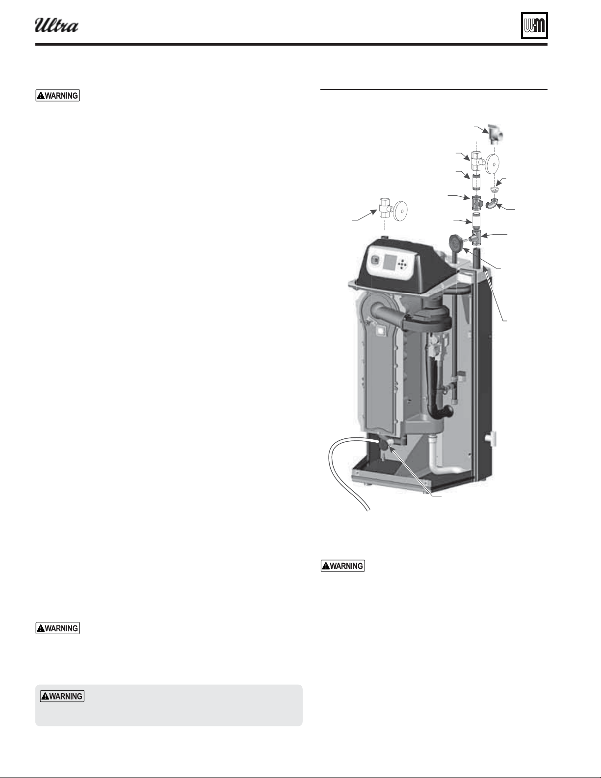
Perform hydrostatic pressure test
Pressure test boiler before permanently attaching water or gas piping
or electrical supply.
Prepare boiler for test
1. See Figure 2 for reference in following steps.
2. Remove supply line tees* and 3/4” elbow from accessory bag.
Pipe to boiler supply connection as shown. Use pipe dope spar-
ingly. (* 1”x1”x1/4” and *1”x1”x3/4” tees with Ultra-80 to -230
or * 1-1/4”x1-1/4”x1/4” and *1-1/4”x1-1/4”x3/4” tees with Ultra
299/310/399.
3. Temporarily plug the ¾” relief valve tapping in the street elbow
with a ¾” NPT pipe plug.
4. Connect a hose to the boiler drain valve, the other end connected
to a fresh water supply. Make sure the hose can also be used to
drain the boiler after test.
5. Connect a nipple and shutoff valve to system supply connection
on the supply tee. This valve will be used to bleed air during the
fi ll. (Valve and nipple are not included with boiler.)
6. Connect a shutoff valve to system return connection. (Valve is not
included with boiler.)
7. To avoid getting water on boiler, you may want to pipe street elbows
on top of shutoff valves and attach catch-buckets beneath.
8. If convenient, install the boiler circulator and any other piping
compatible with Figure 2 that would still allow bleeding air from
shutoff valves.
9. Follow guidelines in this manual for piping components, locations
and sizing.
Fill and pressure test
1. Open the shutoff valves you installed on supply and return con-
nections.
2. Slowly open boiler drain valve and fresh water supply to fi ll boiler
with water. The boiler will fi ll quickly because of its low water
content.
3. When water reaches shutoff valves, close boiler drain valve.
4. Close shutoff valves.
5. Slowly reopen boiler drain valve until test pressure on the pres-
sure/temperature gauge reaches at least 45 psig, but no higher
than 55 psig.
6. Hold at test pressure for 10 minutes.
Do not leave boiler unattended. A cold water fi ll could
expand and cause excessive pressure, resulting in severe
personal injury, death or substantial property damage.
7. Make sure constant gauge pressure has been maintained through-
out test. Check for leaks. Repair if found.
Failure to do so
can damage boiler, resulting in substantial property
damage.
Do not use petroleum-based cleaning or seal-
ing compounds in boiler system. Gaskets and
seals in the system may be damaged. This can
result in substantial property damage.
Drain and remove fi ttings
1. Disconnect fi ll water hose from water source.
2. Drain boiler through drain valve. Remove hose after
draining.
3. Remove nipples and valves unless they will remain for
use in the system piping.
4. Remove plug from relief valve street elbow. See page 9
to install relief valve.
Figure 2drostatic test pipin connections
6
$POOFDUIPTFGSPNCPJMFSESBJOWBMWFUPGSFTIXBUFSTVQQMZ
%SBJOWBMWF
4VQQMZQJQF
/15PO
6MUSBUP
6MUSB
/15PO
6MUSB
5FNQPSBSZTIVUPGG
WBMWFPOCPJMFSTVQQMZ
5FNQPSBSZ
TIVUPGGWBMWFPO
CPJMFSSFUVSO
ÑTUSFFU
FMCPXTVQQMJFE
XJUICPJMFSMPPTF
YYÑPS
YYÑUFF
TVQQMJFEXJUI
CPJMFSMPPTF
ÑQMVH
SFNPWFBGUFS
UFTUJOH
/JQQMFPS
/15
3FNPWFÑQMVHGSPNTUSFFUFMCPXBOEJOTUBMMSFMJFGWBMWF
BGUFSIZESPTUBUJDUFTUJOHJTDPNQMFUFE'PMMPXJOTUSVDUJPOT
JOUIJTNBOVBM
YYPS
YYUFF
TVQQMJFEXJUI
CPJMFSMPPTF
/JQQMFPS
/15
1SFTT5FNQFS
HBVHFTVQQMJFE
XJUICPJMFSMPPTF
®
Series 4
gas-fired water boiler — Boiler Manual
Part number 550-100-400/0119
9
Install water piping
Use two wrenches when tightening water piping at boiler,
using one of the wrenches to prevent the boiler interior
piping from turning. Failure to support the boiler piping
connections to prevent them from turning could cause
damage to boiler components.
General piping information
Additional controls, when required
The U-Control module uses temperature sensors to
provide both high limit protection and modulating tem-
perature control. The U-Control module also provides
low water protection by sensing the temperature of the
heat exchanger. Some codes/jurisdictions may require
additional external controls for high limit and/or low
water cutoff protection.
Additional limit controls
Following standard industry practices, if installation is to comply with
ASME or Canadian requirements, an additional high temperature limit
may be needed. Consult local requirements for other codes/standards
to determine if needed.
1. Install a manual reset high temperature limit constructed to prevent
a temperature setting above 200°F in system supply piping between
boiler and isolation valve. (Note that the U-Control module op-
erating limit function shuts the boiler down at 195°F, or lower if
set to a lower value.)
— If the heating system
includes circuits that require lower temperature water
(radiant slab circuits, for example) as well as higher
temperature circuits, it is recommended to protect low-
temperature circuits with limit controls that are wired to
a U-Control external limit circuit (P13 terminals 1 and 2
for manual reset, or P13 terminals 3 and 4 for automatic
reset).
2. See instructions beginning on page 30 for wiring information.
a. Manual reset operation: If external limit controls are to cause
of the U-Control module, connect series-wired
isolated contacts to P13 terminals 1 and 2 (see page 30 for wir-
ing information).
b. Automatic reset operation: If external limit controls are to cause
of the U-Control module, connect series-
wired isolated contacts to P13 terminals 3 and 4 (see page 30
for wiring information).
c. If using a manual reset limit control or wiring in the manual
reset circuit, set U-Control boiler limit at least 20°F less than
the external manual reset limit (i.e., set U-Control no higher
than 180°F for a 200°F external limit, for example).
Separate low water cutoff
1. A low water cutoff device is recommended when the boiler is in-
stalled above piping level, and may be required by certain state or
local codes or insurance companies. Consult local requirements to
determine. See the NOTICE above regarding the inherent protec-
tion provided by the U-Control module.
2. The U-Control’s integral protection is accepted in many jurisdic-
tions as meeting the requirement for low water protection. See
page 95 for details.
3. When required, use a low water cutoff designed for water
installations. Electrode probe-type is recommended. See
Replacement parts section at the end of this manual for
the Weil-McLain low water cut-off kit.
4. Purchase low water cutoff and install in a tee in the
supply piping above boiler.
5. See fi eld wiring instructions beginning on page 30 for
wiring additional limit controls.
Backfl ow preventer
1. Use backfl ow check valve in cold water supply as re-
quired by local codes.
Instal l r elief valve
1. Install relief valve in ¾” street elbow piped from boiler
supply piping tee ( Figure 2, page 8 ). Pipe the relief valve
only as shown, in the location shown.
2. Connect discharge piping to safe disposal location, fol-
lowing guidelines in the
below.
:
Discharge line must be connected to relief
valve outlet and run to a safe place of
disposal. Terminate the discharge line in
a manner that will prevent possibility of
severe burns or property damage should
the valve discharge.
Discharge line must be as short as possible
and be the same size as the valve discharge
connection throughout its entire length.
Discharge line must pitch downward
from the valve and terminate at least 6”
above the fl oor drain where any discharge
will be clearly visible.
The discharge line shall terminate plain,
not threaded, with a material serviceable
for temperatures of 375 °F or greater.
Do not pipe the discharge to any place
where freezing could occur.
No shutoff valve shall be installed be-
tween the relief valve and boiler, or in the
discharge line. Do not plug or place any
obstruction in the discharge line.
Test the operation of the valve after fi ll-
ing and pressurizing system by lifting
the lever. Make sure the valve discharges
freely. If the valve fails to operate cor-
rectly, replace it with a new relief valve.
Failure to comply with the above guide-
lines could result in failure of the relief
valve to operate, resulting in possibility
of severe personal injury, death or sub-
stantial property damage.
®
Series 4
gas-fired water boiler — Boiler Manual
Part number 550-100-400/0119
10
Install water piping (continued)
System water pip ing methods
All piping methods shown in this manual use primary/
secondary connection to the boiler loop. These designs
ensure proper fl ow through the Ultra boiler, for the most
effi cient and reliable operation of the boiler and the heat-
ing system. For other piping methods, consult your local
Weil-McLain representative or see separate Ultra boiler
piping guides.
Circulators
The boiler circulator (Taco 007 for Ultra-80 and -105; Taco 0014 for
Ultra-155, -230, and -299/310; Taco 0013 for Ultra-399) is shipped
loose. Locate it in the return piping, as shown in the appropriate pip-
ing diagram in this manual.
use the boiler circulator in any location other
than the ones shown in this manual. The boiler circula-
tor is selected to ensure adequate fl ow through the Ultra
boiler.
Install the boiler circulator only on the boiler return pip-
ing. This ensures the pressure drop through the boiler
will not cause low pressure in the circulator intake.
Failure to comply could result in unreliable performance
and nuisance shutdowns from insuffi cient fl ow.
Circulator fl ow rate
Size circulators based on the fl ow rate required to achieve the tem-
perature change needed. You can closely estimate temperature rise (or
drop) through a circuit by using the following formula, where TD is
temperature rise (or drop), FLOW is fl ow rate (in gpm), and BTUH
is the heat load for the circuit:
=
:
Consider a system loop for a system with total heating load equal to
210,000 Btuh. The desired temperature drop through the system piping
is 20°F. Then the required fl ow rate is:
=
=
Circulator head requirement
The circulator must be capable of delivering the required fl ow against
the head loss that will occur in the piping. Determine the pipe size
needed and the resultant head loss using accepted engineering meth-
ods. The simplifi ed pipe sizing here is limited to residential systems,
and does not include systems with fan coil units or radiant tubing.
The following simplifi ed method for pipe and circulator
sizing must be limited to residential applications using
baseboard (fi nned or cast iron), cast iron radiators or
convectors. DO NOT apply for radiant heating, fan coil
units or commercial installations.
Simplifi ed pipe/circulator selection
1. Install the boiler and piping using the recommended
piping layouts beginning on page 12 and in the AD-
VANCED section of this manual.
2. Size the piping and components for each circuit in the
space heating system using Figure 3 .
a. Determine the heating load (Btuh) for each circuit.
b. Calculate the fl ow rate for each circuit using its load.
To use a 20°F temperature drop, just divide the
MBH (1,000’s of Btuh) by 10.
Example — Flow for 20°F temp drop with 35,000 Btuh:
FLOW = 35 MBH / 10 = 3.5 gpm
c. Find the pipe size in
Figure 3 that has a max fl ow rate just
larger than that required for the circuit.
d. Find the total equivalent length (TEL) of the circuit.
TEL accounts for losses through fi ttings and valves by
using the equivalent length of pipe that would cause the
same head loss. Add these numbers to the measured length
of the circuit to fi nd TEL in feet.
TEL is usually close to 1.5 times the length of
the circuit for residential baseboard, radiator or
convector applications.
e. Measure the length of each circuit from the circulator
outlet back to its inlet. Then multiply this length times
1.5 to get the approximate TEL of the circuit.
f. Find the head loss for each circuit:
(feet)
(feet water column)
g. NOTE: Size system header piping for the total fl ow of all
connected zones.
3. Example:
a. For a circuit with heating load = 45,000 Btuh (= 45 MBH).
Measured length of circuit is 88 feet.
b. Flow = 45 MBH / 10 = 4.5 gpm.
c. TEL = 1.5 x 88 feet = 132 feet.
d. From Figure 3 , select 1" pipe (max fl ow = 7.1 gpm).
e. Head loss = TEL x 0.04 = 132 x 0.04 = 5.28 feet.
f. Select a circulator that can deliver at least 4.5 gpm at a
head of 5.28 feet. (Read the NOTICE below.)
To use this method, limit the fl ow through ¾"
fi nned-tube baseboard to 3.9 gpm, or use 1"
baseboard and limit fl ow to 7.1 gpm. If the
total load of the circuit requires more fl ow,
split the circuit into two or more.
Also see Figure 10, page 15 for quick-selection
information for applications using Taco 007
circulators or equivalent for zone piping.
Figure 3
lo rates for
0.04 feet head loss per foot
of pipe
ater
Pipe size
(inches)
MAX Flow rate (GPM)
@ 0.04 feet per foot
Pipe size
(inches)
MAX Flow rate (GPM)
@ 0.04 feet per foot
¾
3.9
45
7.1
75
16
140
24
290
®
Series 4
gas-fired water boiler — Boiler Manual
Part number 550-100-400/0119
11
In stall water piping (continued)
Expansion tank and make-up water
1. Ensure expansion tank size will handle boiler and system water
volume and temperature. Allow 3 gallons for boiler and its piping.
Undersized expansion tanks cause system water to be
lost from relief valve and make-up water to be added
through fi ll valve. Eventual boiler failure can result due
to excessive make-up water addition.
2. Tank must be located as shown in this manual, or following rec-
ognized design methods. See tank manufacturer’s instructions
for details. When installing air vents and expansion tanks, refer to
manufacturer’s instructions.
3. Connect the expansion tank to the air separator only if the separa-
tor is on the suction side of the circulator. Always install the system
fi ll connection at the same point as the expansion tank connection
to the system.
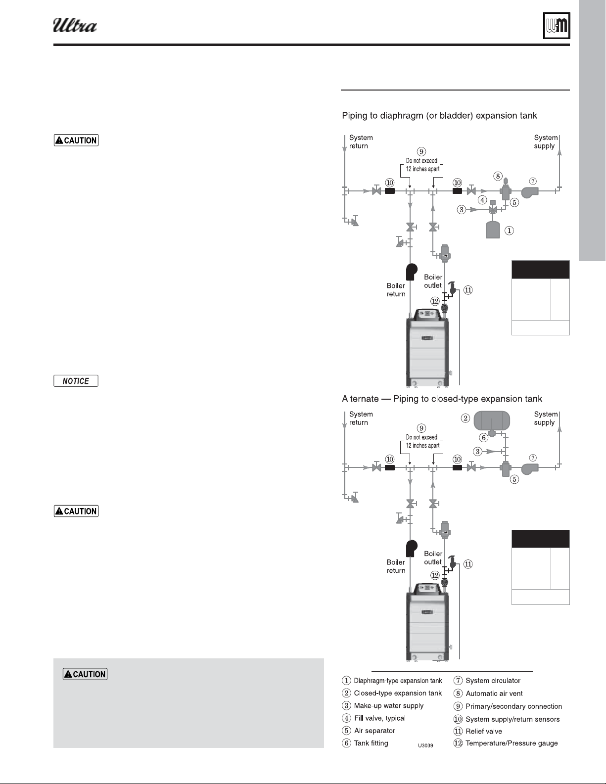
4. Most piping drawings in this manual show diaphragm expansion
tanks. See Figure 4 for piping from air separator to expansion tank
and make-up water line using a closed-type expansion tank.
5. Most chilled water systems are piped using a closed-type tank, as
shown in Figure 51, page 55 .
Diaphragm (or bladder) expansion tank
1. ( Figure 4 ) Always install an automatic air vent on top of the air
separator to remove residual air from the system.
When using diaphragm or bladder tanks only — when the
boiler is installed above the system main piping, install
an automatic air vent in the top of the outgoing boiler
piping to prevent air pocketing.
Closed-ty pe expansion tank
1. See Figure 4 , Alternate, for piping connections when using a closed-
type expansion tank.
2. Pitch any horizontal piping up towards tank 1 inch per 5 feet of
piping. Connect to tank with at least ¾” piping to allow room for
air to rise.
DO NOT install automatic air vents on closed-type
expansion tank systems. Air must remain in the system
and return to the tank to provide its air cushion. An au-
tomatic air vent would cause air to leave system, resulting
in water-logging the expansion tank.
DO NOT use a closed-type expansion tank on a system
with a Weil-McLain AQUA PLUS water heater. The water
heater must use an automatic air vent. Operation of the
automatic air vent will deplete air in the piping, causing
the expansion tank to waterlog.
Figure 4pansion tan pipin
Use the pipe size shown in
Figure 4 on all boiler loop piping (connecting boiler
to and from the primary/secondary connection,
item 9).
Failure to follow these guidelines could
result in system problems.
Boiler loop pipe size
Ultra-80, 105
Ultra-155, 230
Ultra-299/310,
399
1”
1¼”
1½”
See CAUTION at left.
Boiler loop pipe size
Ultra-80, 105
Ultra-155, 230
Ultra-299/310,
399
1”
1¼”
1½”
See CAUTION at left.
®
Series 4
gas-fired water boiler — Boiler Manual
Part number 550-100-400/0119
12
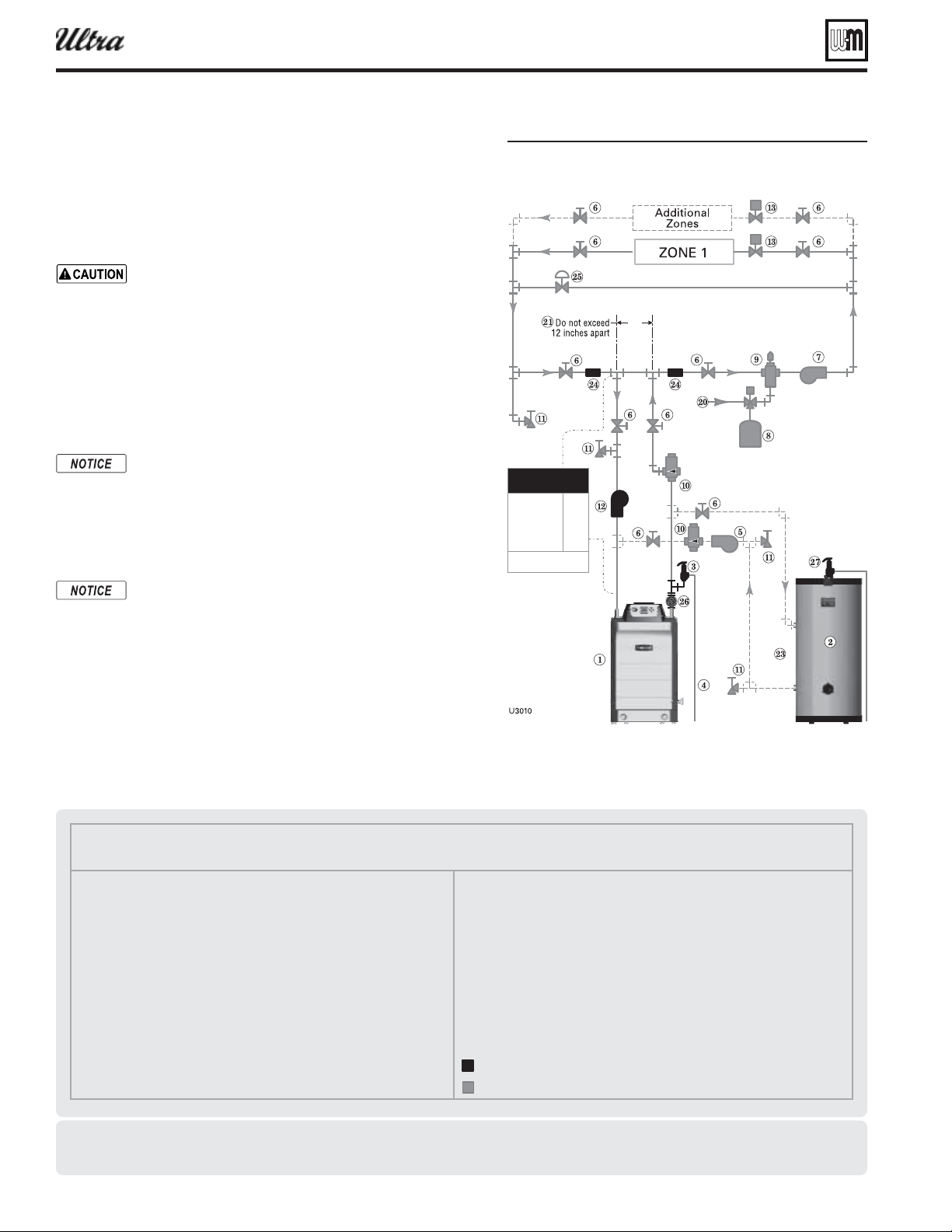
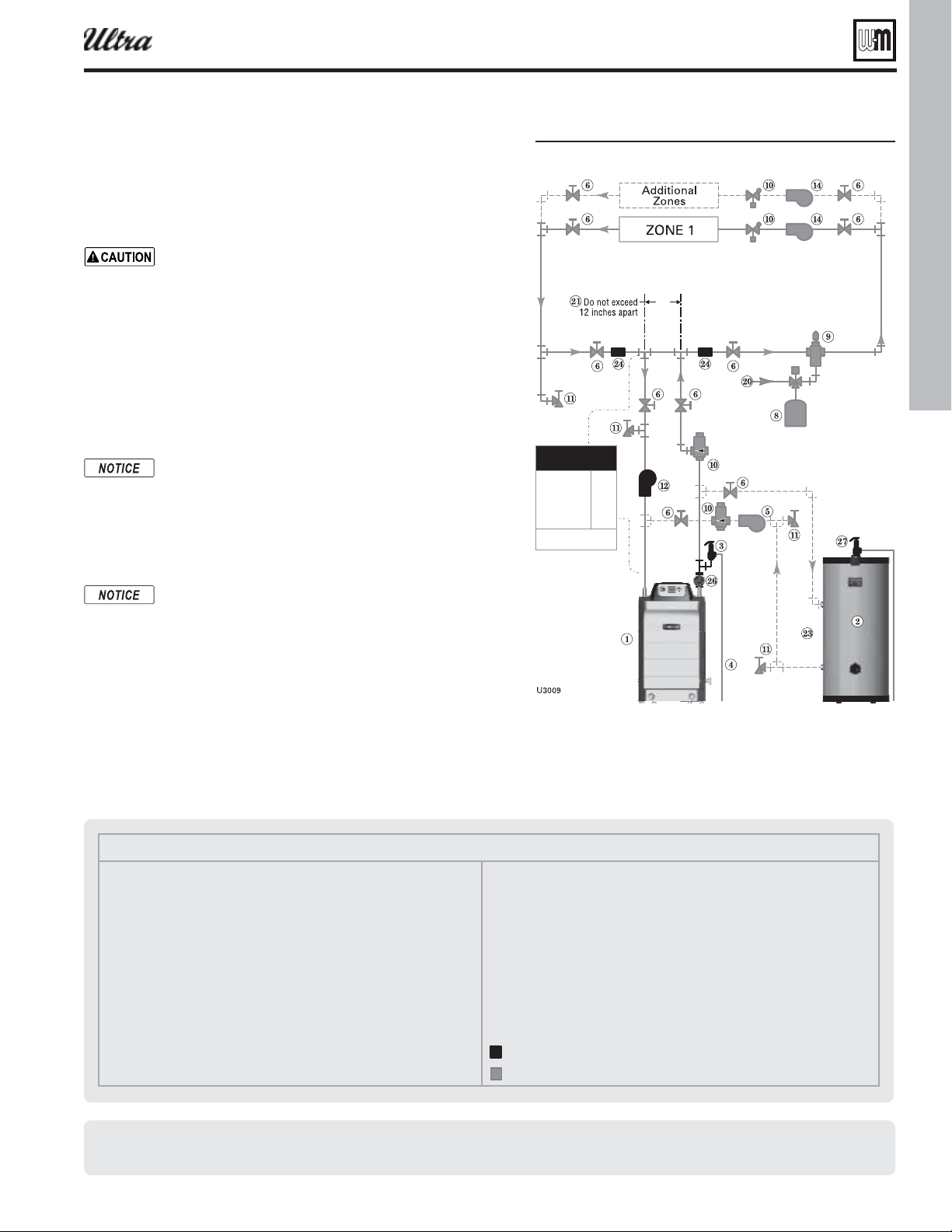
Legend — Figure 5
1 Ultra boiler
2 Indirect water heater (DHW), if used
3 Boiler relief valve (see page 9 for piping details)
4 Relief valve discharge piping (see page 9 for details)
5 DHW circulator (see page 56 for suggested sizing)
6 Isolation valves
7 System circulator (see information above for wiring)
8 Diaphragm (or bladder) type expansion tank (see page 56 for piping of
closed-type expansion tank, if used)
9 Air separator [with automatic air vent only on systems using diaphragm
(or bladder) type expansion tank]
10 Flow/check valves
11 Purge/drain valves
12 Boiler circulator
13 Zone valves, typical
20 Make-up water supply
21 Primary/secondary connection
23 DHW connections — see water heater manual for piping
24 Strap system supply and return sensors to lines as shown, at least 6 pipe
diameters (but no more than 3 feet) from boiler connection tees.
25 Systems using high-head pumps may require a bypass pressure regulator
to prevent damage to control valves.
26 Temperature/Pressure gauge
27 DHW relief valve, if used
Items supplied with boiler
Items supplied by others
Install water piping — typical systems
Figure 5one ale onin plus optional pipin
Zoning with zone valves
1. Connect boiler to system as shown in Figure 5 when zone valve
zoning. The primary/secondary piping shown ensures the boiler
loop will have suffi cient fl ow. It also avoids applying the high head
of the boiler circulator to the zone valves. Also see the information
on page 14 and page 15 for suggested piping and sizing.
Use the pipe size shown in Figure 5
on all boiler loop piping (connecting boiler to and from
the primary/secondary connection, item 21).
Failure to fol-
low these guidelines could result in system problems.
2. When using a closed-type expansion tank, connect the expansion
tank and make-up water piping as shown in Figure 4, page 11 . (DO
NOT use a closed-type tank with a AQUA PLUS water heater.)
3. Connect DHW (domestic hot water) piping to indirect storage
water heater as shown.
By default, the U-Control Module turns off space heating
during DHW heating (if DHW input is priority 1). The
boiler circulator will turn off, preventing hot water from
circulating to the system (optional time out setting can
be used to override). The fl ow/check valve shown on the
boiler outlet piping prevents gravity circulation in the
boiler loop during DHW heating.
Overriding the Outdoor Reset function by setting control to
DHW mode when system is intended for space heating may
violate Section 303 of the 2007 Energy Act. See page 137 for
compliance information and exemptions.
4. Controlling the circulators
a. The U-Control can control up to three circulators (boiler cir-
culator and two others). Refer to Field wiring, beginning on
page 30 , for instructions on wiring to circulators.
b. The factory default settings are: DHW circulator as Circula-
tor 1, boiler circulator as Circulator 2 and system circulator
as Circulator 3. See Field wiring instructions, beginning on
page 30 , for details.
Other piping alternatives
See page 14 and page 15 and ADVANCED INSTALLATION section for additional piping suggestions.
Boiler loop pipe size
Ultra-80, 105
Ultra-155, 230
Ultra-299/310,
399
1”
1¼”
1½”
See CAUTION at left.
®
Series 4
gas-fired water boiler — Boiler Manual
Part number 550-100-400/0119
13
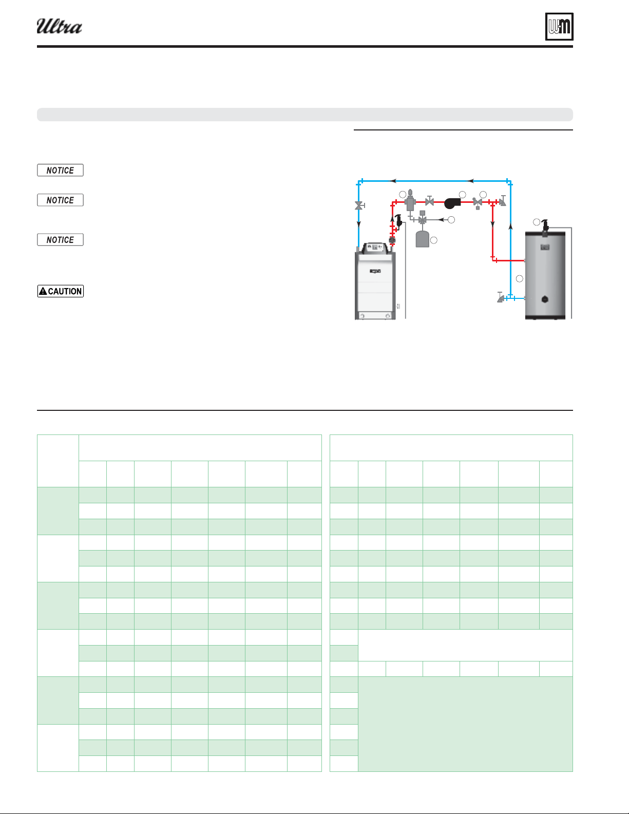
Legend — Figure 6
1 Ultra boiler
2 Indirect water heater (DHW), if used (see page 56 )
3 Boiler relief valve (see page 9 for piping details)
4 Relief valve discharge piping (see page 9 for details)
5 DHW circulator (see page 56 for suggested sizing)
6 Isolation valves
7 System circulator (see information above for wiring)
8 Diaphragm (or bladder) type expansion tank (see page 56 for piping of
closed-type expansion tank, if used)
9 Air separator [with automatic air vent only on systems using diaphragm
(or bladder) type expansion tank]
10 Flow/check valves
11 Purge/drain valves
12 Boiler circulator
14 Zone circulators, typical
20 Make-up water supply
21 Primary/secondary connection (tees no more than 12 inches apart)
23 DHW connections — see water heater manual for piping
24 Strap system supply and return sensors to lines as shown, at least 6 pipe
diameters (but no more than 3 feet) from boiler connection tees.
26 Temperature/Pressure gauge
27 DHW relief valve, if used
Items supplied with boiler
Items supplied by others
Install water piping — typical systems (continued)
Figure 6Circulator onin plus optional pipin
Zoning with circulators
1. Connect boiler to system as shown in Figure 6 when circulator
zoning. The boiler circulator cannot be used for a zone. It must
supply only the boiler loop. Also see the information on page 14
and page 15 for suggested piping and sizing.
Use the pipe size shown in Figure 6
on all boiler loop piping (connecting boiler to and from
the primary/secondary connection, item 21).
Failure to fol-
low these guidelines could result in system problems.
2. Install a separate circulator for each zone.
3. When using a closed-type expansion tank, connect the expansion
tank and make-up water piping as shown in Figure 4, page 11 . (DO
NOT use a closed-type tank with a AQUA PLUS water heater.)
4. Connect DHW (domestic hot water) piping to indirect storage
water heater as shown.
By default, the U-Control Module turns off space heating
during DHW heating (if DHW input is priority 1). The
boiler circulator will turn off, preventing hot water from
circulating to the system (optional timeout setting can
be used to override). The fl ow/check valve shown on the
boiler outlet piping prevents gravity circulation in the
boiler loop during DHW heating.
Overriding the Outdoor Reset function by setting control to
DHW mode when system is intended for space heating may
violate Section 303 of the 2007 Energy Act. See page 137 for
compliance information and exemptions.
5. Controlling the circulators
a. The U-Control can control up to three circulators (boiler cir-
culator and two others). Refer to Field wiring, beginning on
page 30 , for instructions on wiring to circulators.
b. The factory default settings are: DHW circulator as Circula-
tor 1, boiler circulator as Circulator 2. See Field wiring instruc-
tions, beginning on page 30 , for details.
c. The zone circulators in Figure 6 must be controlled by circula-
tor relays activated by the zone thermostats or zone controller.
Other piping alternatives
See page 14 and page 15 and ADVANCED INSTALLATION section for additional piping suggestions.
Boiler loop pipe size
Ultra-80, 105
Ultra-155, 230
Ultra-299/310,
399
1”
1¼”
1½”
See CAUTION at left.
®
Series 4
gas-fired water boiler — Boiler Manual
Part number 550-100-400/0119
14
Using w ith Weil-McLain AQUA PLUS water heaters
See - roduct anual for tpical ater pipin.
AQUA PLUS DHW installation — quick-
selection
The information in this section is for usage of Ultra boilers
with Weil-McLain AQUA PLUS indirect water heaters.
For dedicated DHW applications, use the circulator supplied
with the boiler to circulate to the water heater as shown in
this section.
By default, the U-Control Module turns off space heating dur-
ing DHW heating (if DHW input is priority 1). The boiler cir-
culator will turn off, preventing hot water from circulating to
the system (optional timeout setting can be used to override).
DO NOT use a closed-type expansion tank on a system with
a Weil-McLain AQUA PLUS water heater. The water heater
must use an automatic air vent. Operation of the automatic
air vent will deplete air in the piping, causing the expansion
tank to waterlog. Always use a diaphragm- or bladder-type
expansion tank with AQUA PLUS water heaters.
1. Follow the guidelines on this page and page 15 to connect the water
heater to the boiler. Use Figure 8 for dedicated water heating-only
applications. Use Figure 10 and Figure 9, page 15 for combined space
heating/water heating applications.
See ADVANCED INSTALLATION section for additional piping information and applications.
Figure 7 Use the tale elo to sie loop pipin and select a circulator see AANC section for other tans
40 6.5 71/71 160/124 8.5 1 007 40 6.5 71/71 160/124 8.5 1 007
60 6.5 71/71 168/132 8.5 1 007 60 6.5 71/71 168/132 8.5 1 007
80 6.5 71/71 176/140 8.5 1 007 80 6.5 71/71 176/140 8.5 1 007
40 10.1 94/94 217/154 17.0 1¼ 0014 40 6.4 94/86 203/141 8.6 1 007
60 6.4 94/94 211/162 8.6 1 007 60 6.4 94/94 211/162 8.6 1 007
80 6.4 94/94 219/170 8.6 1 007 80 6.4 94/94 219/170 8.6 1 007
40 12.1 119/98 248/160 15.9 1¼ 0014 40 12.1 119/98 248/160 15.9 1¼ 0014
60 12.1 139/120 295/220 15.9 1¼ 0014 60 12.1 139/120 295/220 15.9 1¼ 0014
80 12.1 139/139 305/230 15.9 1¼ 0014 80 12.1 139/139 305/230 15.9 1¼ 0014
40 13.5 120/100 251/162 15.2 1¼ 0014 40
Not recommended — boiler capacity
exceeds maximum output of water heater
60 18.4 169/128 350/207 23.7 1½ 1400-20 60
80 13.5 207/207 430/325 15.2 1¼ 0014 80 13.5 207/207 430/325 15.2 1¼ 0014
40 13.1 120/100 250/162 9.7 1¼ 0010 40
Not recommended —
boiler capacity exceeds
maximum output of water heater
60 19.3 170/129 351/208 11.7 1½ 0014 60
80 24.9 252/252 510/381 18.4 1½ 1400-20 80
40 13.1 120/100 250/162 9.7 1¼ 0010 40
60 19.3 170/129 351/208 11.7 1½ 0014 60
80 24.9 320/253 636/382 18.4 1½ 1400-20 80
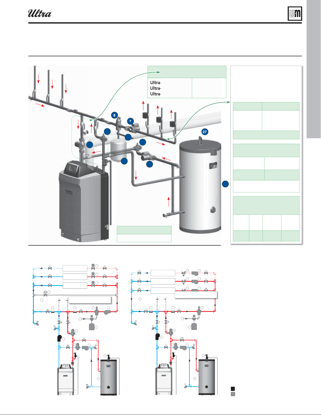
Figure 8 Ultra oiler ith Ultra LUS or AUA
LUS ater heater dedicated ater
heatin application tpical pipin
schematic
6
2. The AQUA PLUS water heater can also be installed
as one of the zones in the system. This method,
however, requires fl ow through the main system
even during the summer (non-space heating)
months. Piping as shown in Figure 10 and Fig-
ure 9, page 15 allows isolation of fl ow to just the
water heater piping during non-heating periods.
®
Series 4
gas-fired water boiler — Boiler Manual
Part number 550-100-400/0119
15
6
"EEJUJPOBM
;POFT
%POPUFYDFFE
JODIFTBQBSU
;0/&
;0/&
6
"EEJUJPOBM
;POFT
%POPUFYDFFE
JODIFTBQBSU
;0/&
;0/&
Figure 9 Ultra oiler ith Ultra LUS or AUA LUS ater heater tpical pipin
schematics
for Figure 10 and Figure 9
DHW circulator (see page 56 for sug-
gested sizing)
System circulator (provided by installer)
Diaphragm type expansion tank ONLY
— DO NOT use a closed-type tank with
AQUA PLUS water heaters, because the
automatic air vent will deplete the air
from the system, causing the expansion
tank to waterlog.
Air separator with automatic air vent
Flow/check valves
Boiler circulator — provided with boiler
Zone valves, typical
Make-up water supply
Primary/secondary connection
DHW connections — see water heater
manual for piping
Strap system supply and return sensors
to lines as shown, at least 6 pipe diam-
eters (but no more than 3 feet) from
boiler connection tees.
Systems using high-head pumps may
require a bypass pressure regulator to
prevent damage to control valves.
DHW relief valve must be installed in the
tapping on top of the AQUA PLUS water
heater.
Items supplied with boiler
Items supplied by others
For residential space heating appli-
cations (other than radiant heating
or unit heaters) ONLY, you can use:
-80
-105, -155
-230
-299/310, 399
1” or larger
1¼” or larger
1½” or larger
2” or larger
Recommendations are based on a 20°F temp
drop through the system.
Zone piping selection for series loops
with fi nned-tube baseboard — general
Copper pipe and
baseboard size
Max recommended
feet of baseboard
¾"
1"
106
179
Contact your supplier to size the system and zone
circulators needed. See below for zone piping
using Taco 007 or equivalent circulators.
Limits for series loop zones with
fi nned-tube baseboard using
Taco 007 (or equivalent) circulators
Copper
pipe and
baseboard
Max
load
MBH
Max feet of
baseboard
Max total
length of
circuit (feet)
¾"
1"
50
79
82
104
93
123
Figure 10 Ultra oiler ith Ultra LUS or AUA LUS- - or - ater heater one ale onin tpical pipin
12
20
23
27
10
10
7
5
9
8
Boiler loop pipe size
Ultra-80, -105
Ultra-155, -230
Ultra-299/310, 399
1” or larger
1¼” or larger
1½ or larger
DHW loop pipe size
See Figure 7, page 14
®
Series 4
gas-fired water boiler — Boiler Manual
Using with Weil-McLain AQUA PLUS water heaters
(cont.)
See - roduct anual for tpical ater pipin.
Part number 550-100-400/0119
16
Venting/air piping — general
®
Series 4
gas-fired water boiler — Boiler Manual
Figure 11 Corrosie contaminants and sources
Do not install the Ultra boiler into a common vent with
any other appliance. This will cause fl ue gas spillage or ap-
pliance malfunction, resulting in possible severe personal
injury, death or substantial property damage.
Existing common vent systems may be too large for the
appliances remaining connected after the existing boiler
is removed.
Failure to follow all instructions can result in fl ue gas
spillage and carbon monoxide emissions, causing severe
personal injury or death.
When removing a boiler from an existing
common vent system
. When an existing boiler is replaced with an Ultra boiler, the Ultra
boiler CANNOT use the existing common vent. The Ultra boiler requires
its own vent and air piping, as specifi ed in this manual. This may cause a
problem for the appliances that remain on the old common vent, because
the vent may be too large. The following test is intended to check for proper
operation of the appliances remaining on the old common vent system.
Vent system verifi cation
At the time of removal of an existing boiler, the following steps shall be
followed with each appliance remaining connected to the common venting
system placed in operation, while the other appliances remaining connected
to the common venting system are not in operation. Seal any unused open-
ings in the common venting system.
Existing vent test procedure
(The following is intended to test whether the appliances
remaining on an existing vent system will operate
satisfactorily.)
1. Visually inspect the venting system for proper size and horizontal pitch
and determine there is no blockage or restriction, leakage, corrosion or
other defi ciencies which could cause an unsafe condition.
2. Test vent system — Insofar as is practical, close all building doors and
windows and all doors between the space in which the appliances
remaining connected to the common venting system are located and
other spaces of the building. Turn on clothes dryers and any appliance
not connected to the common venting system. Turn on any exhaust
fans, such as range hoods and bathroom exhausts, so they will oper-
ate at maximum speed. Do not operate a summer exhaust fan. Close
fi replace dampers.
3. Place in operation the appliance being inspected. Follow the lighting
instructions. Adjust thermostat so appliance will operate continuously.
4. Test for spillage at draft hood relief opening after 5 minutes of main
burner operation. Use the fl ame of a match or candle, or smoke from
a cigarette, cigar, or pipe.
5. After it has been determined that each appliance remaining connected
to the common venting system properly vents when tested as outlined
herein, return doors, windows, exhaust fans, fi replace dampers, and
any other gas-burning appliance to their previous conditions of use.
Any improper operation of common venting system should be corrected
so the installation conforms with the National Fuel Gas Code, ANSI Z223.1
— latest edition. Correct by re-sizing to approach the minimum size as
determined using the appropriate tables in Part 13 of that code. Canadian
installations must comply with B149.1 or B149.2 Installation Code.
Products to avoid
Spra cans containin chloro uorocarons
ermanent ae solutions
Chlorinated aescleaners
Chlorine-ased simmin pool chemicals
Calcium chloride used for thain
Sodium chloride used for ater softenin
efrierant leas
aint or arnish remoers
drochloric acidmuriatic acid
Cements and lues
Antistatic faric softeners used in clothes drers
Chlorine-tpe leaches deterents and cleanin
solents found in household laundr rooms
Adhesies used to fasten uildin products and other
similar products
cessie dust and dirt
.
— Install air inlet piping for the Ultra
boiler as described in the Boiler manual and this ad-
dendum. The air termination fi tting must be installed
with the clearances and geometry relative to the vent
outlet depicted in this manual to ensure that fl ue
products do not enter the air intake.
— Provide combustion air openings
to boiler room/building as specifi ed in this adden-
dum and as required by all applicable codes.
.
place combustion air supply opening or intake near
a swimming pool, for example. Avoid areas subject
to exhaust fumes from laundry facilities. These areas
will always contain contaminants.
Contaminated combustion air will damage the boiler,
resulting in possible severe personal injury, death or
substantial property damage.
Areas likely to have contaminants
r cleaninlaundr areas and estalishments
Simmin pools
etal farication plants
Beaut shops
efrieration repair shops
hoto processin plants
Auto od shops
lastic manufacturin plants
urniture re nishin areas and estalishments
Ne uildin construction
emodelin areas
araes ith orshops
Buildings under construction (where air is contaminated
with particulates)
Part number 550-100-400/0119
17
Venting/air piping — general (continued)
®
Series 4
gas-fired water boiler — Boiler Manual
.
.
common vent with any other appliance.
See page 16.
Inspect fi nished vent and air piping thoroughly
to ensure all are airtight and comply with the
instructions provided and with all require-
ments of applicable codes.
Failure to provide a properly-installed vent and
air system will cause severe personal injury or
death.
Venting/combustion air piping - Installations
must provide provisions for combustion and
ventilation air in accordance with the sec-
tion “Air for Combustion and Ventilation,” of
the National Fuel Gas Code - ANSI Z223.1/
NFPA54 – latest edition, or Sections 8.2, 8.3,
or 8.4 of Natural Gas and Propane Installation
Code - CAN/CSA B149.1, or applicable provi-
sions of the local building codes.
Use only the materials listed in this manual for
vent and air pipe and fi ttings. Failure to comply
could result in severe personal injury, death or
substantial property damage.
If used, a masonry chimney can ONLY be used
as a PIPE CHASE for vent and air pipes —
The vent and air piping must be installed as
instructed in this manual and all joints must
be sealed. The chimney must be used only for
Ultra boilers. NO OTHER appliance or fi re-
place can be connected to the chimney.
The chimney must be straight, with no offsets,
and the vent and air piping materials must
comply with this instruction manual.
The chimney must be fi tted with a sealed ac-
cess opening, through which the interior of the
chimney can be inspected.
The chimney and liner must be inspected at
least once annually to verify condition.
Failure to comply could result in severe personal
injury, death or substantial property damage.
Combustion air piping
1. Combustion air must be piped from outside to the boiler,
following the instructions in this manual, and compliant with
all applicable codes. Read the warning in Figure 11, page 16,
and ensure the air intake will not be likely to draw in con-
taminated air.
2. Combustion air can be piped individually for each boiler, or
it can be manifolded as shown in Figure 59, page 59 . Air pip-
ing must always terminate on the same side (or roof ) of the
building as the vent.
Vent piping
1. Boiler fl ue gases must be piped from the boiler to outside, fol-
lowing the instructions in this manual, and compliant with all
applicable codes. The vent pipe must terminate either through
the sidewall or through the roof, located with the correct
separation from the air termination. See Figure 14, page 18,
and the associated instructions referenced.
2. Each Ultra boiler requires a separate vent. Do not common
vent.
Vent and air piping materials
1. See Figure 13, page 19 for approved vent and air piping
materials.
Part number 550-100-400/0119
18
®
Series 4
gas-fired water boiler — Boiler Manual
Venting & air — general (cont.)
Figure 12 Vent and air pipe options and maximum allowable piping lengths
Ultra model
Vent or air
pipe size
t.BYJNVNFRVJWBMFOUGFFUPGQJQJOH
t/VNCFSPGFMCPXTBMMPXFEBUUIFTFMFOHUIT
(All applications include allowance for the terminations.)
Direct vent
Sidewall
with
Weil-McLain
vent/air cap
Direct vent
Sidewall with
separate pipes
— or —
%JSFDUFYIBVTU
(sidewall or vertical)
3” Concentric
Sidewall or Vertical
DO NOT use CPVC
or ABS
[Note 1]
4” Concentric
Sidewall or Vertical
DO NOT use CPVC
or ABS)
[Note 1]
Direct vent
Vertical
with separate
pipes
Direct vent
Vertical exhaust
Sidewall air
Direct vent
only
Direct vent or
Direct exhaust
Direct vent
only
Direct vent
only
Direct vent
only
Direct vent
only
Length Ells Length Ells Length Ells Length Ells Length Ells Length Ells
-80/105
2” * 100 (ab) 2 100 (a) 2 100 (ab) 1 NA 100 (a) 1 100 (a) 1
3” 100 2 100 2 100 1 NA 100 1 100 1
-155 3” 100 2 100 2 100 1 NA 100 1 100 1
-230
3” 30 (c) 2 30 (c) 2 30 (c) 1 30 (c)(d) 1 30 (c) 1 30 (c) 1
4” 100 (d) 2 100 2 70 (d) 1 100 1 100 1 100 1
-299 4” 100 2 100 2 70 (d) 1 100 1 100 1 100 1
-310
4” 100 2 100 2 70 (d) 1 100 1 100 1 100 1
-399 4” 100 2 100 2 NA 100 1 100 1 100 1
Note 1:
IPEX 3” and 4” PVC concentric vent kits can be used with standard PVC pipe, fi ttings and cement (ANSI/ASTM D1785)
except where ULC S636 compliance is required. For ULC S636 compliance, all pipe, fi ttings and cement must be IPEX
System 636. When using IPEX kits, use only IPEX product code 196006 for 3” venting or IPEX product code 196021 for 4”
venting.
Contact Weil-McLain for ordering information and availability of Weil-McLain venting kits.
Polypropylene - Separate pipe and concentric termination by respective manufacturers.
Additional
notes
a —
Use 3”x2” reducer at boiler
b —
Use 3”x2” reducers at termination
c —
Use 4”x3” reducer at boiler
d —
Use 4”x3” reducers at termination
* Ultra-80 and 105 boilers installed with 2-inch vent piping automatically derate due to the pressure loss in the vent and air
piping. The derate ranges up to 10% for the Ultra-80 at 100 feet or 15% for the Ultra-105 at 100 feet.
Equivalent feet for elbows — deduct from maximum equivalent length of
piping:
Stainless steel (AL29-4C) vent pipe
install an adapter at the boiler for all applications. Also install
an adapter at the termination unless using separate-pipe
termination.
Part number 550-100-400/0119
19
®
Series 4
gas-fired water boiler — Boiler Manual
Venting & air — general (cont.)
Figure 13 Vent and air piping materials Use onl the materials listed elo ensurin that all materials meet local
codes
PVC schedule 40 ANSI/ASTM D1785
Plastic vent pipe must be
certifi ed to ULC S636 when
required. (Note 2)
Air pipe can be any of those
listed at left if acceptable for
local codes.
PVC-DWV (Note 1) ANSI/ASTM D2665
CPVC schedule 40 (Note 1) ANSI/ASTM F441
ABS-DWV schedule 40 (Note 1) ANSI/ASTM D2661
PVC ANSI/ASTM D2564
CPVC (Note 1) ANSI/ASTM F493
ABS (Note 1) ANSI/ASTM D2235
Polypropylene
vent pipe,
¿ ttings,
terminations
Obtain all materials from
M&G Simpson-Duravent
Obtain all materials from Centrotherm
See manufacturer’s literature for detailed
information
MUST USE LOCKING COLLAR ON
EVERY JOINT
ULC S636
Heat Fab, Inc. — Saf-T-Vent
®
Z-Flex, Inc. — Z-Vent II
Simpson Dura-Vent — FasNSeal™
Certifi ed for Category IV and direct vent
appliance venting
Certifi ed for Category IV and
direct vent
appliance venting
(purchase separately)
For 2” or 3” vent or air termination
(cut to size if necessary)
3” vent screen:
W-M part number 383-500-105
For 3” or 4” vent or air termination
(cut to size if necessary)
4” vent screen:
W-M part number 383-500-110
Note 1: DO NOT use DWV, CPVC or ABS when using concentric vent termination. Use ONLY PVC schedule 40.
Note 2: IPEX PVC concentric terminations utilize PVC pipe/fi ttings certifi ed to ULC S636. Where ULC S636 compliance is required, use
only IPEX System 636 pipe, fi ttings and cement.
AL29-4C vent piping — Install a PVC-to-stainless adapter supplied by the vent pipe manufacturer at the boiler vent connection
and at the termination (when using Weil-McLain plate or concentric PVC termination). DO NOT mix piping from different vent
pipe manufacturers unless using adapters specifi cally designed for the purpose by the manufacturer.
Plastic piping — Do not attempt to connect different types of plastic piping together.
DO NOT use cellular core pipe.
All vent and air pipes require a where specifi ed in the manual or vent supplement. Purchase
bird screens separately from Weil-McLain or vent kit supplier. Note that most kits do not include the screens.
Part number 550-100-400/0119
20
®
Series 4
gas-fired water boiler — Boiler Manual
Sidewall vent/air termination: Separate pipes
Figure 14
eet los eet los eet los
- 100 2 100 2
Not
alloed
- 100 2 100 2
- Not alloed 100 2
- Not alloed 30 2 100 2
- Not alloed Not alloed 100 2
- Not alloed Not alloed 100 2
Install pipe reducers to adapt from pipe sie used to the outside
diameter reuired at the oiler. ou do not hae to reduce allo-
ale pipe lenth for the reducers.
Ultra- and oilers installed ith -inch ent pipin
automaticall derate due to the pressure loss in the ent and air
pipin. The derate ranes up to for the Ultra- at feet
or for the Ultra- at feet.
or pipin usin more than elos reduce maimum alloale
lenth
feet for each additional -inch elo or
feet for each additional or -inch lon radius elo
feet for each or -inch short radius elo
feet for each or -inch -deree elo.
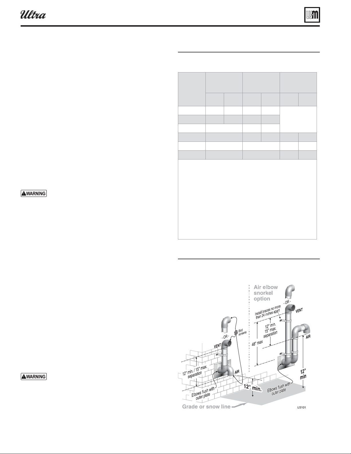
Figure 15 Sideall termination separate pipes
con uration options and minimum clearances
from ent to air terminations
Allowable vent/air pipe materials
1. Use only the materials listed in Figure 13, page 19 .
2. The Weil-McLain vent termination kit includes inside and
outside wall plates, bird screens, and mounting hardware to
secure the plates (kit included with boiler).
Maximum piping length
1. Locate the terminations such that the total air piping and vent
piping from the boiler to the termination will not exceed the
maximum length given in Figure 14 .
2. Maximum lengths listed in Figure 14 allow for 2 elbows. Ad-
ditional elbows required a reduction in maximum length as
explained in the table notes.
Connecting from termination to boiler
1. Install the terminations as instructed in the following. Then
proceed to page 82 to complete the air and vent piping be-
tween the termination and the boiler.
Determine location — separate elbows
A gas vent extending through an exterior wall shall
not terminate adjacent to the wall or below build-
ing extensions such as eaves, parapets, balconies
or decks. Failure to comply could result in severe
personal injury, death or substantial property dam-
age.
1. Locate the vent/air terminations using the following guide-
lines.
2. The air piping must terminate in a down-turned elbow as
shown in Figure 15 . This arrangement avoids recirculation
of fl ue products into the combustion air stream.
a. Apply the confi guration on the left side of Figure 15 unless
the terminations would fail to meet minimum clearance
to grade or snow line.
b. Apply the confi guration on the right side of Figure 15
when the terminations need to be raised higher to meet
clearance to grade or snow line.
c. The vent and air pipes may run up as high as 4 feet, as
shown in Figure 15 right side with no enclosure. The vent
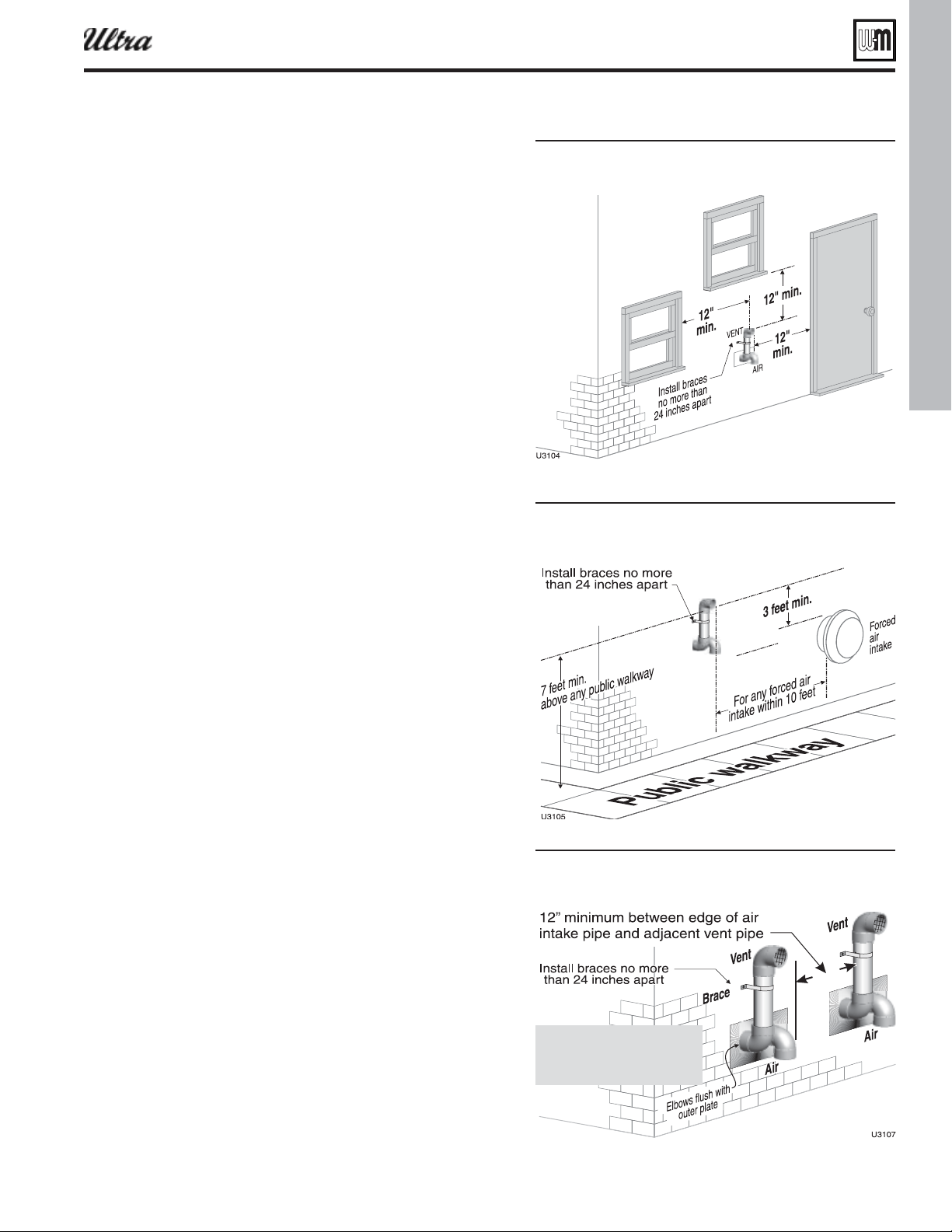
and air pipes must be secured with braces, and all clear-
ances and lengths must be maintained. Space braces no
further than 24 inches apart. (See WARNING below for
extremely cold climates.)
d. External venting greater than 4 feet requires an insulated
enclosure around the vent and air pipes. The vent and air
terminations must exit through the enclosure as shown
in Figure 15 , maintaining all required clearances.
3. The vent piping must terminate in an elbow pointed outward
or away from the air inlet, as shown in Figure 15 .
Do not exceed the maximum lengths of the outside
vent piping shown in Figure 15 . Excessive length
exposed to the outside could cause freezing of con-
densate in the vent pipe, resulting in potential boiler
shutdown. In extremely cold climates, install an
insulated chase around the vent piping, particularly
when using longer lengths. The chase must allow
for inspection of the vent pipe, and insulation must
be protected from water.
Part number 550-100-400/0119
21
Figure 16 Sideall termination ith separate pipes
clearances to openins
Figure 17 Sideall termination ith separate pipes
clearances to pulic ala or forced air
intae
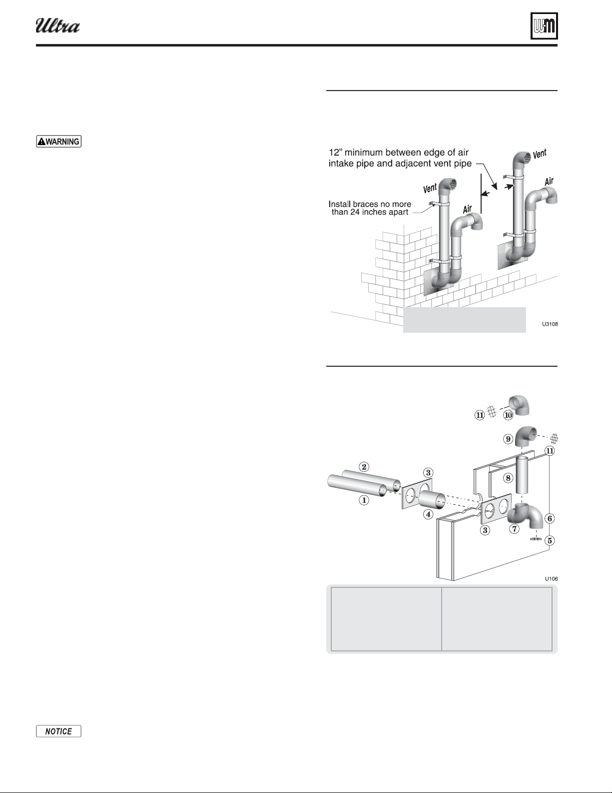
Figure 18 ultiple terminations separate pipes
clearance from ent of one to air intae of the
net
®
Series 4
gas-fired water boiler — Boiler Manual
Sidewall vent/air termination: Separate pipes (continued)
4. You must consider the surroundings when terminating the vent
and air:
a. Position the vent termination where vapors will not damage
nearby shrubs, plants or air conditioning equipment or be
objectionable.
b. The fl ue products will form a noticeable plume as they con-
dense in cold air. Avoid areas where the plume could obstruct
window views.
c. Prevailing winds could cause freezing of condensate and
water/ice buildup where fl ue products impinge on building
surfaces or plants.
d. Avoid possibility of accidental contact of fl ue products with
people or pets.
e. Do not locate the terminations where wind eddies could affect
performance or cause recirculation, such as inside building
corners, near adjacent buildings or surfaces, window wells,
stairwells, alcoves, courtyards or other recessed areas.
f. Do not terminate above any door or window or under a deck.
Condensate can freeze, causing ice formations.
g. Locate or guard vent to prevent condensate damage to exterior
fi nishes.
5. Maintain clearances as shown in the illustrations in this manual
section. Also maintain the following:
a. Vent must terminate:
At least 6 feet from adjacent walls.
No closer than 5 feet below roof overhang.
At least 7 feet above any public walkway.
At lease 3 feet above any forced air intake within 10 feet.
No closer than 12 inches below or horizontally from any
door or window or any other gravity air inlet.
b. Do not terminate closer to 4 feet horizontally from any electric
meter, gas meter, regulator, relief valve or other equipment.
Never terminate above or below any of these within 4 feet
horizontally.
6. Locate terminations so they are not likely to be damaged by
foreign objects, such as stones or balls, or subject to buildup of
leaves or sediment.
7. Do not connect any other appliance to the vent pipe or multiple
boilers to a common vent pipe.
Completing the vent/air piping
1. Install vent/air penetrations as explained in the following pages
before installing vent and air piping from the boiler to the termi-
nations. Insert piping from boiler air and vent connections, then
attach exterior termination piping.
2. Follow instructions beginning on page 71 to complete piping from
boiler to termination.
Part number 550-100-400/0119
22
Sidewall vent/air termination: Separate pipes (continued)
Figure 19 ultiple terminations separate pipes
clearance from ent of one to air intae of the
net alternate con uration of air and ent
terminations
Figure 20 Sideall termination asseml usin
separate pipes
1 Vent piping
2 Air piping
3 Sidewall termination plates, by
installer
4 Galvanized thimbles, by installer
5 Bird screen (air), by installer
6 Air inlet elbow
7 Elbow
8 Nipple
9 Elbow (vent termination)
10 Alternate elbow orientation
11 Bird screen (vent termination) —
supplied by installer
®
Series 4
gas-fired water boiler — Boiler Manual
Multiple vent/air terminations
1. When terminating multiple Ultra boilers, terminate each vent/air
connection as described in this manual.
All vent pipes and air inlets must terminate at the same
height to avoid possibility of severe personal injury, death
or substantial property damage.
2. Place wall penetrations to obtain minimum clearance of 12 inches
between vent pipe and adjacent air inlet elbow, as shown in Fig-
ure 18, page 21 for U. S. installations.
3. For Canadian installations, provide clearances required by Natural
Gas and Propane Installation
CAN/CSA
B149.1 or B149.2 Instal-
lation Code.
4. The air inlet of an Ultra boiler is part of a direct vent connection.
It is not classifi ed as a forced air intake with regard to spacing from
adjacent boiler vents.
5. Combustion air (NOT vent piping) can be manifolded as shown
in Figure 59, page 59 .
Prepare wall penetrations
1. Air pipe penetration:
a. Cut a hole for the air pipe. Size the air pipe hole as close as desired
to the air pipe outside diameter.
2. Vent pipe penetration:
a. Cut a hole for the vent pipe. For either combustible or noncom-
bustible construction, size the vent pipe hole at least 0.4” larger
than the vent pipe diameter:
2¾” hole for 2”
4” hole for 3”
5” hole for 4”
b. Insert a galvanized metal thimble in the vent pipe hole as shown
in Figure 20 .
3. Use a sidewall termination plate as a template for correct location of
hole centers. Sidewall termination plates must be purchased sepa-
rately. See the parts list at the end of this manual for part numbers.
4. Follow all local codes for isolation of vent pipe when passing through
fl oors or walls.
5. Seal exterior openings thoroughly with exterior caulk.
Termination and fi ttings
1. Prepare the vent termination elbow and the air termination elbow
( Figure 20 ) by inserting bird screens. Bird screens must be pur-
chased separately. See the parts list at the end of this manual for
part numbers.
2. When completed, the air termination coupling must be oriented
at least 12 inches below the vent termination and at least 12 inches
above grade or snow line as shown in Figure 15, page 20.
3. You can orient the vent termination elbow either directly outward
or 90 degrees away from the air inlet elbow as shown in Fig-
ure 15, page 20.
4. Maintain the required dimensions of the fi nished termination piping
as shown in Figure 15, page 20.
5. Do not extend exposed vent pipe outside of building more than
shown in this document. Condensate could freeze and block vent
pipe.
If extending the vent and air pipes out from the wall,
install a coupling on each pipe. Mount the piping with
the coupling fl ush with the outer plate.
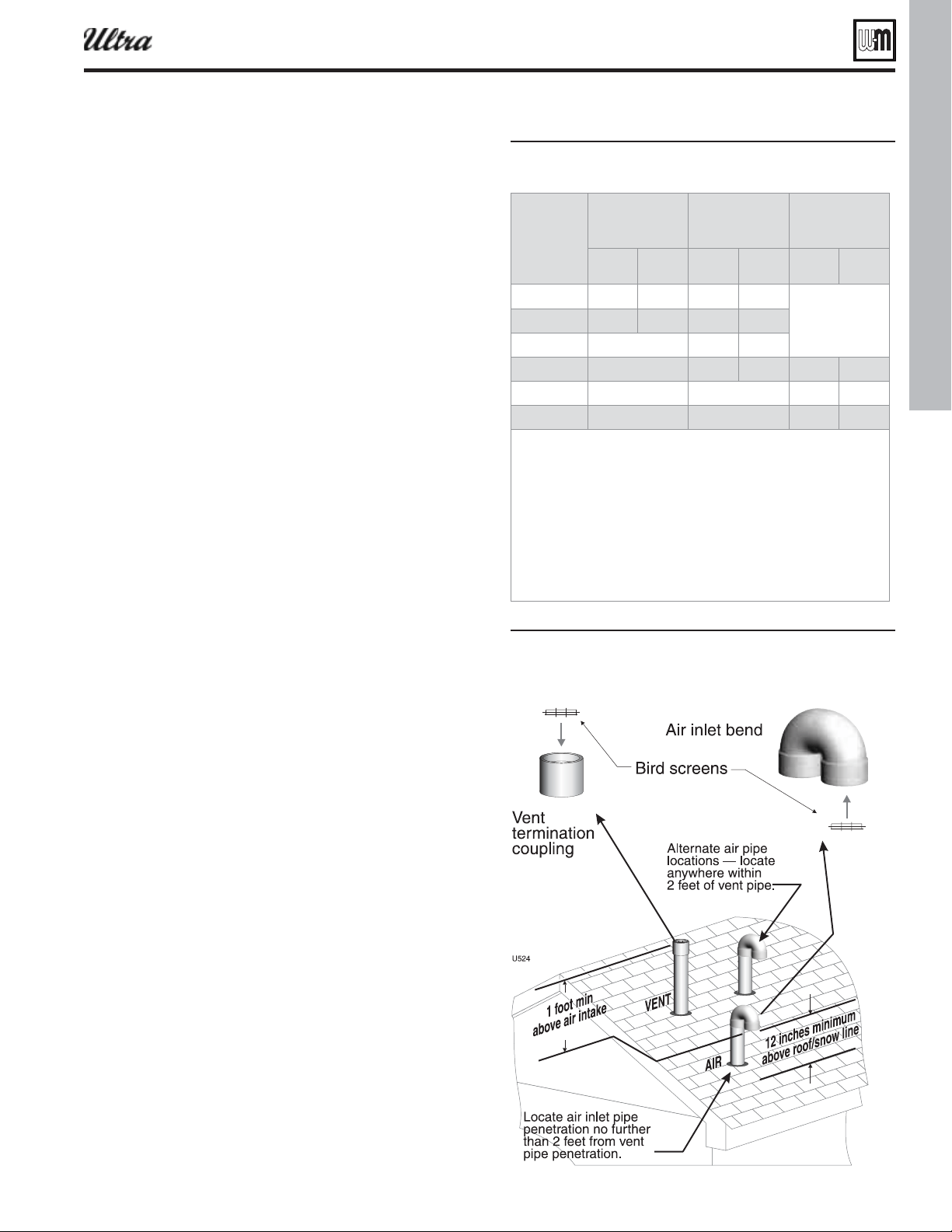
Part number 550-100-400/0119
23
Figure 21
eet los eet los eet los
- 30 1 100 1
Not
alloed
- 30 1 100 1
- Not alloed 100 1
- Not alloed 30 1 100 1
- Not alloed Not alloed 100 1
- Not alloed Not alloed 100 1
Install reducers as necessar here connectin to the oiler
ent and air connections.
or pipin usin more than elo reduce maimum alloale
lenth
feet for each additional -inch elo or
feet for each additional
or -inch lon radius elo
feet for each or -inch short radius elo
feet for each or -inch -deree elo.
NOT The -deree return end is included in the alloed t-
tins. No deduction is reuired.
Figure 22ertical termination separate pipes
®
Series 4
gas-fired water boiler — Boiler Manual
Vertical vent/air termination: Separate pipes
Allowable vent/air pipe materials
1. Use only the materials listed in Figure 13, page 19 .
2. Purchase bird screens for vent and air terminations separately.
See the parts list at the end of this manual.
Maximum piping length
1. Locate the terminations such that the total air piping and vent
piping from the boiler to the termination will not exceed the
maximum length given in Figure 21 .
2. Maximum lengths listed in Figure 21 allow for 1 elbow. Ad-
ditional elbows required a reduction in maximum length as
explained in the table notes.
Connecting from termination to boiler
1. Install the termination penetrations as instructed in the follow-
ing. Then proceed to page 82 to complete the piping between
the termination and the boiler.
Determine location
1. Locate the vent/air terminations using the following guidelines:
2. The air piping must terminate in a down-turned 180-degree
return bend as shown in Figure 22 . Locate the air inlet pipe
no further than 2 feet from the center of the vent pipe. This
placement avoids recirculation of fl ue products into the com-
bustion air stream.
3. The vent piping must terminate in an up-turned coupling as
shown in Figure 22 . The top of the coupling must be at least 1
foot above the air intake. The air inlet pipe and vent pipe can
be located in any desired position on the roof, but must always
be no further than 2 feet apart and with the vent termination
at least 1 foot above the air intake.
4. You must consider the surroundings when terminating the
vent and air:
a. Position the vent termination where vapors will not dam-
age nearby shrubs, plants or air conditioning equipment
or be objectionable.
b. The fl ue products will form a noticeable plume as they
condense in cold air. Avoid areas where the plume could
obstruct window views.
c. Prevailing winds could cause freezing of condensate and
water/ice buildup where fl ue products impinge on building
surfaces or plants.
d. Avoid possibility of accidental contact of fl ue products
with people or pets.
e. Do not locate the terminations where wind eddies could
affect performance or cause recirculation, such as inside
building corners, near adjacent buildings or surfaces,
window wells, stairwells, alcoves, courtyards or other
recessed areas.
f. Do not terminate above any door or window. Condensate
can freeze, causing ice formations.
g. Locate or guard vent to prevent condensate damage to
exterior fi nishes.
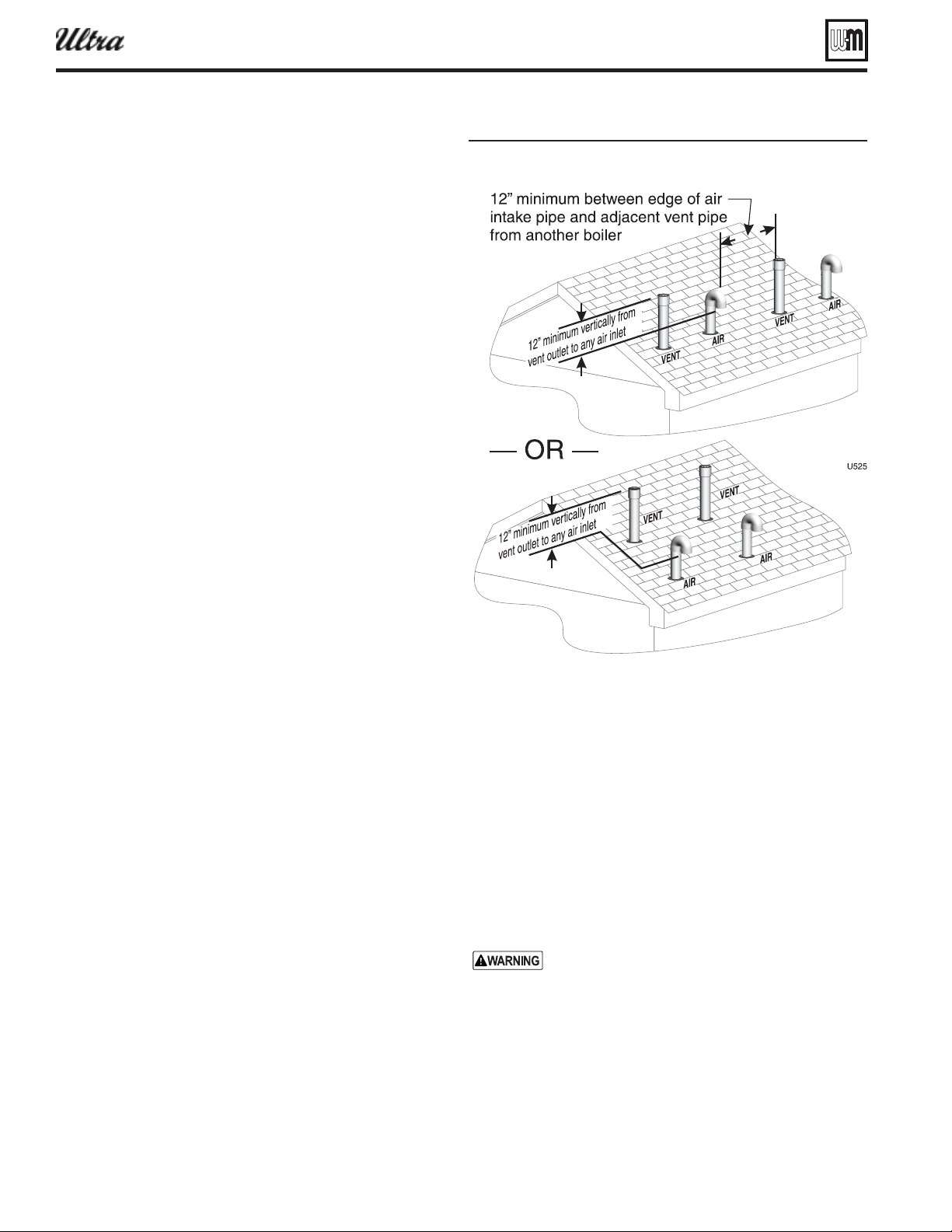
Part number 550-100-400/0119
24
®
Series 4
gas-fired water boiler — Boiler Manual
5. Maintain clearances to vent termination as given below:
a. Vent must terminate:
At least 6 feet from adjacent walls.
No closer than 5 feet below roof overhang.
At least 7 feet above any public walkway.
At least 3 feet above any forced air intake within
10 feet.
No closer than 12 inches below or horizontally from
any door or window or any other gravity air inlet.
b. Air inlet must terminate at least 6 inches above the roof or
snow line and at least 12 inches below the vent termina-
tion as shown in Figure 22, page 23 .
c. Do not terminate closer to 4 feet horizontally from any
electric meter, gas meter, regulator, relief valve or other
equipment. Never terminate above or below any of these
within 4 feet horizontally.
6. Locate terminations so they are not likely to be damaged by
foreign objects, such as stones or balls, or subject to buildup
of leaves or sediment.
7. Do not connect any other appliance to the vent pipe or mul-
tiple boilers to a common vent pipe.
Prepare roof penetrations
1. Air pipe penetration:
a. Cut a hole for the air pipe. Size the air pipe hole as close
as desired to the air pipe outside diameter.
2. Vent pipe penetration:
a. Cut a hole for the vent pipe. For either combustible or
noncombustible construction, size the vent pipe hole at
least 0.4” larger than the vent pipe diameter:
2¾” hole for 2”
4” hole for 3”
5” hole for 4”
b. Insert a galvanized metal thimble in the vent pipe hole.
3. Space the air and vent holes to provide the minimum spacings
shown in Figure 22, page 23 .
4. Follow all local codes for isolation of vent pipe when passing
through fl oors, ceilings and roofs.
5. Provide fl ashing and sealing boots sized for the vent pipe
and air pipe.
Termination and fi ttings
1. Prepare the vent termination elbow and the air termination
elbow ( Figure 22, page 23 ) by inserting bird screens. Bird
screens must be purchased separately. See the parts list at the
end of this manual for part numbers.
a. If using 3-inch piping for an Ultra-230, cut a 4-inch bird
screen by placing 3-inch fi tting on screen and cutting
around it as a template.
2. The air piping must terminate in a down-turned 180-degree
return bend as shown in Figure 22, page 23 . Locate the air
inlet pipe no further than 2 feet from the center of the vent
pipe. This placement avoids recirculation of fl ue products
into the combustion air stream.
Vertical vent/air termination: Separate pipes (continued)
Figure 23 Termination location separate pipes
terminations for multiple oilers
3. The vent piping must terminate in an up-turned coupling as
shown in Figure 22, page 23 . The top of the coupling must be
at least 1 foot above the air intake. The air inlet pipe and vent
pipe can be located in any desired position on the roof, but
must always be no further than 2 feet apart and with the vent
termination at least 1 foot above the air intake.
4. Maintain the required dimensions of the fi nished termination
piping as shown in Figure 22, page 23 .
5. Do not extend exposed vent pipe outside of building more
than shown in this document. Condensate could freeze and
block vent pipe.
Multiple vent/air terminations ( Figure 23 )
1. When terminating multiple Ultra boilers, terminate each vent/
air connection as described in this section.
Terminate all vent pipes at the same height and all
air pipes at the same height to avoid possibility of
severe personal injury, death or substantial property
damage.
2. Place roof penetrations to obtain minimum clearance of
12 inches between edge of air intake elbow and adjacent vent
pipe of another boiler for U. S. installations (see Figure 2).
For Canadian installations, provide clearances required by
Natural Gas and Propane Installation
CAN/CSA
B149.1 or
B149.2 Installation Code.
3. The air inlet of an Ultra boiler is part of a direct vent con-
nection. It is not classifi ed as a forced air intake with regard
to spacing from adjacent boiler vents.

Part number 550-100-400/0119
25
®
Series 4
gas-fired water boiler — Boiler Manual
DIRECT VENT
Figure 24DIRECT VENT
DIRECT VENT
SIDEWALL termination
DIRECT VENT
VERTICAL termination
DIRECT VENT
VERTICAL vent and
SIDEWALL air
6CX
7&/5
"*3
674CX
7&/5
"*3
Step 1 Install the boiler.
Step 2 Determine the termination method — sidewall or vertical, concentric or separate pipes, etc.
Step 3 Determine proper location for wall or roof penetration for each termination.
Step 4 Install termination assembly as described in this manual.
Step 5 Install air and vent piping from boiler to termination.
Step 6 Install pipe supports and brackets as required.
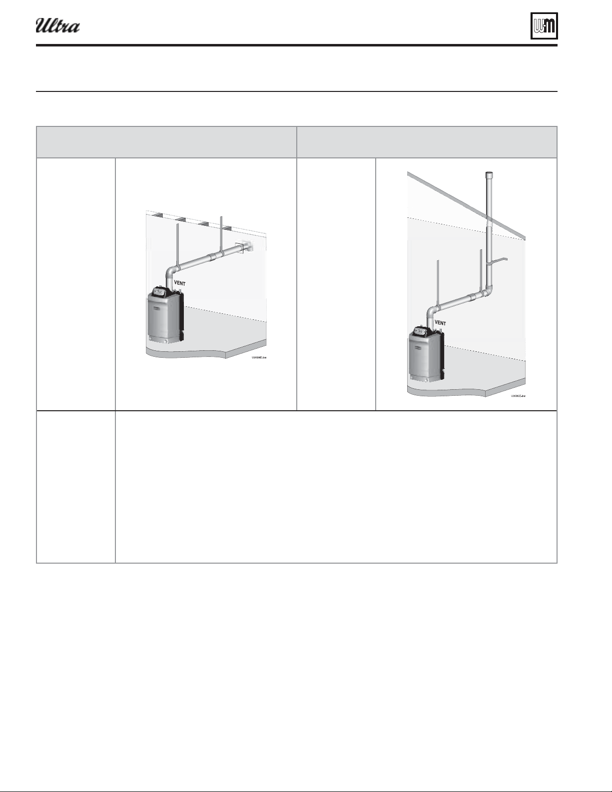
Part number 550-100-400/0119
26
®
Series 4
gas-fired water boiler — Boiler Manual
DIRECT EXHAUST
Figure 25DIRECT EXHAUST
DIRECT EXHAUST
Sidewall termination
DIRECT EXHAUST
Vertical termination
Step 1 Install the boiler.
Step 2 Determine the proper location for roof or wall penetration for each termination.
Prepare roof penetrations before installing vent piping.
Finish by attaching external pipe and fi ttings as shown in the termination instructions.
Vertical terminations only — Install terminations as described in this addendum.
Support vertical runs on the outside of the building with brackets as shown in the termination
instructions.
Step 3 Install vent piping from boiler to termination.
Install a hanger support within 6 inches of any upturn in the piping.
Slope horizontal piping downward toward the boiler at least 1/4 inch per foot.
Step 4 Connect the vent piping at the boiler per manual instructions.
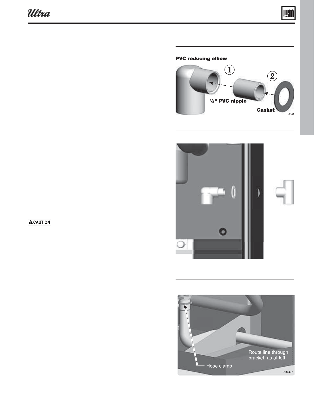
Part number 550-100-400/0119
27
Install condensate line
Figure 26Condensate trap asseml
Figure 27
Figure 28 Condensate drain Ultra- -
®
Series 4
gas-fired water boiler — Boiler Manual
Prepare condensate fi ttings
1. Remove PVC fi ttings and gasket from the accessories bag.
2. Deburr and chamfer outside and inside of ½” x 1¼” PVC nipple
to ensure even cement distribution when joining.
3. Clean nipple ends and all fi ttings. Dry thoroughly.
4. For each joint in the condensate line, apply the following. Assemble
parts ONLY in the order given.
a. Apply primer liberally to both joint surfaces — pipe end and
fi tting socket.
b. While primer is still damp, lightly apply approved cement to
both surfaces in a uniform coating.
c. Apply a second coat of cement to both surfaces. Avoid using
too much cement on sockets to prevent cement buildup inside.
d. With cement still wet, insert pipe into fi tting, twisting ¼ turn.
Make sure pipe is fully inserted.
e. Wipe excess cement from joint. Check joint to be sure a smooth
bead of cement shows around the entire joint.
5. See Figure 26 .
6. Assemble the ½” PVC nipple to the PVC reducing elbow as shown.
7. Allow joint to dry completely.
8. Then slide gasket over nipple as shown in Figure 27 .
9. Slide nipple through jacket condensate line hole to position as
shown in Figure 27 .
10. Cement the ½” tee to the protruding ½” nipple. Be sure both nipple
and reducing elbow fi nish upright.
Firmly press the reducing elbow and the tee together
while the cement sets to ensure the gasket is securely
compressed. The gasket ensures the jacket enclosure is
airtight at this location.
Connect condensate trap line and fi ttings
1. Remove condensate trap line from bag.
2. Figure 28
a. Guide the condensate trap line through the bracket hole as
shown.
b. Place a hose clamp over the end of the condensate line.
c. Then slide the end of the trap line over the heat exchanger
condensate connection.
d. Tighten the hose clamp to secure the trap line.
e. Place a hose clamp over the other end of the condensate trap
line.
f. Slide the trap line over the reducing elbow and secure with
the hose clamp.
3. Ultra-155 and larger — Figure 30, page 28 or Figure 31, page 28
a. Slide a hose clamp over each end of the condensate trap line.
b. Slide the trap line onto the heat exchanger condensate connec-
tion and PVC reducing elbow as shown.
c. Tighten the hose clamps to secure the trap line.
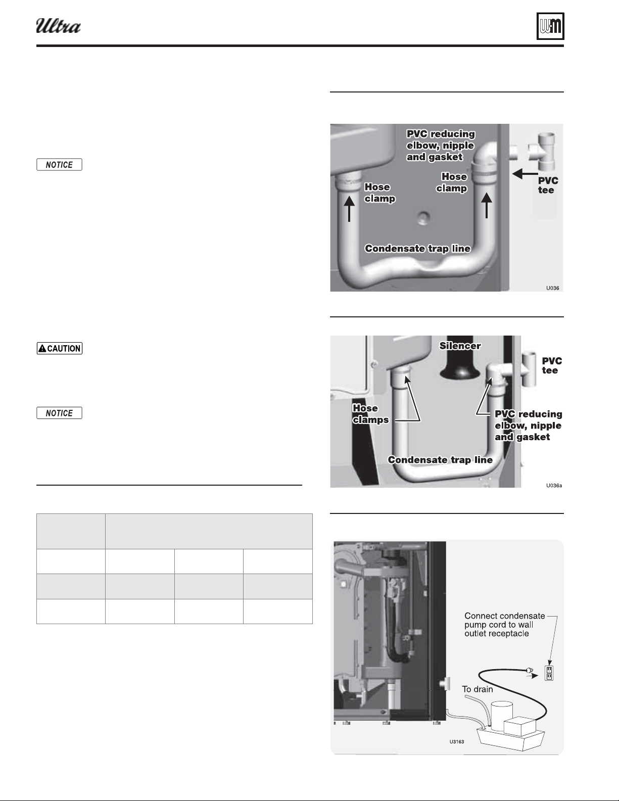
Part number 550-100-400/0119
28
Install condensate line (continued)
Figure 30Condensate drain Ultra- - C
tee installation shon applies to all models
Figure 31Condensate drain Ultra- -
Figure 32 Condensate pump others tpical
®
Series 4
gas-fired water boiler — Boiler Manual
Condensate drain tubing
1. Connect condensate drain tubing to the ½” PVC tee and run to
fl oor drain or condensate pump (see Figure 32 ). Use ½” PVC or
CPVC pipe; or 5/8” I. D. tubing.
Use materials approved by the authority having juris-
diction. In the absence of other authority, PVC and
CPVC pipe must comply with ASTM D1785, F441 or
D2665. Cement and primer must comply with ASTM
D2564, F656, or F493. For Canada, use CSA or ULC
certifi ed PVC or CPVC pipe, fi ttings and cement.
2. Leave the top of the ½” tee OPEN. This is needed as a vacuum
break.
3. When installing a condensate pump, select one approved for use
with condensing boilers and furnaces. The pump should have an
overfl ow switch to prevent property damage from condensate
spillage. See Figure 29 for required fl ow capacity.
4. When sizing condensate pumps, make sure to include the total
load of all Ultra boilers connected to it.
The condensate line must remain unobstructed, allow-
ing free fl ow of condensate. If condensate is allowed
to freeze in the line or if the line is obstructed in any
other manor, condensate can exit from the boiler tee,
resulting in potential water damage to property.
Condensate from the Ultra boiler will be slightly
acidic (typically with a pH from 3.2 to 4.5). Install
a neutralizing fi lter if required by local codes. See
Replacement parts section at the end of this manual
for the Weil-McLain kit.
Figure 29 Suested condensate pump capacit
Boiler
Minimum recommended condensate pump
capacity, per boiler, GPH
Ultra-80 2 Ultra-230 6
Ultra-105 3 Ultra-299/310 8
Ultra-155 4 Ultra-399 8
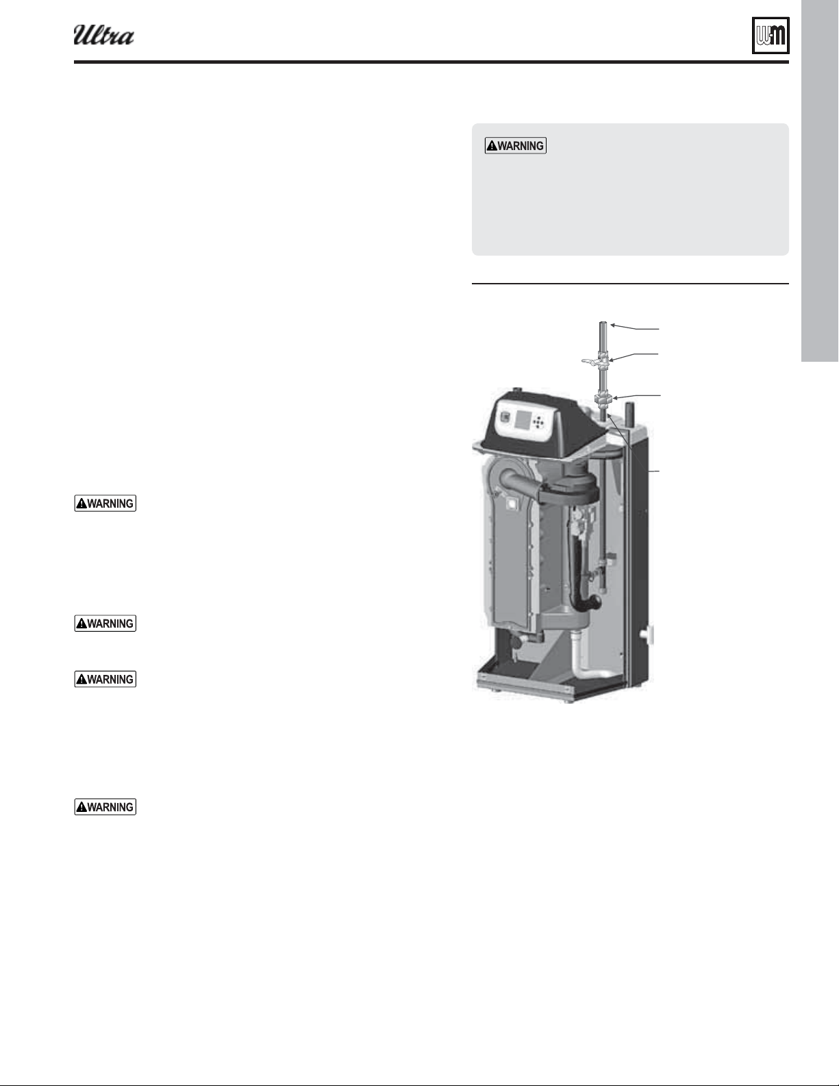
Part number 550-100-400/0119
29
Gas piping
Connecting gas supply piping
1. Remove jacket front panel and refer to Figure 33 to pipe gas to
boiler.
a. Install ground joint union for servicing, when required.
b. Install manual shutoff valve in gas supply piping outside
boiler jacket when required by local codes or utility require-
ments.
c. In Canada — When using manual main shutoff valve, it must
be identifi ed by the installer.
2. Wall-mounted boilers
a. Refer to separate Ultra Boiler Wall-mounting instructions.
b. Gas connection may enter from the bottom of boiler as
explained in the Wall-mounting instructions.
3. Support piping with hangers, not by boiler or its accessories.
4. Purge all air from gas supply piping.
5. Before placing boiler in operation, check boiler and its gas con-
nection for leaks.
a. Close manual main shutoff valve during any pressure testing
at less than 13” w.c.
b. Disconnect boiler and gas valve from gas supply piping dur-
ing any pressure testing greater than 13” w.c.
Do not check for gas leaks with an open fl ame — use
bubble test. Failure to use bubble test or check for gas
leaks can cause severe personal injury, death or sub-
stantial property damage.
6. Use pipe dope compatible with propane gases. Apply sparingly
only to male threads of pipe joints so that pipe dope does not
block gas fl ow.
Failure to apply pipe dope as detailed above can result
in severe personal injury, death or substantial property
damage.
DO NOT adjust or attempt to measure gas valve outlet
pressure. The gas valve is factory-set for the correct
outlet pressure. This setting is suitable for natural gas
and propane, requiring no fi eld adjustment. Attempt-
ing to alter or measure the gas valve outlet pressure
could result in damage to the valve, causing potential
severe personal injury, death or substantial property
damage.
Ultra boilers are shipped ready to fi re natural gas ONLY.
(Exception: Ultra-80LP is propane-ready.) You must
install the propane orifi ce if the boiler will be connected
to propane. See page 48 . Failure to comply could result
in severe personal injury, death or substantial property
damage.
Gas pipe sizing
1. See page 93 for gas line sizing information.
Check gas pressure at inlet to boiler
1. See Figure 39, page 40 , Figure 40, page 40 , or Figure 41, page 41
for location of the gas inlet pressure test port.
Use two wrenches when tightening gas
piping at boiler, using one wrench to pre-
vent the boiler gas line connection from
turning. Failure to support the boiler gas
connection pipe to prevent it from turn-
ing could damage gas line components.
Figure 33
Connect as suppl pipin
Natural gas supply pressure
1. Pressure required at gas valve inlet pressure port:
a. Maximum: 13” w.c. with no fl ow (lockup) or with
boiler on
b. Minimum: 4” w.c. (for all except 5” for -299/310)
with gas fl owing (verify during boiler startup, while
boiler is at high fi re)
2. Install 100% lockup gas pressure regulator in supply line
if inlet pressure can exceed 13” w.c. at any time. Adjust
lockup regulator for 13” w.c. maximum.
Propane supply pressure
1. Adjust propane supply regulator provided by gas sup-
plier for 13” w.c. maximum pressure.
2. Pressure required at gas valve inlet pressure port:
a. Maximum: 13” w.c. with no fl ow (lockup) or with
boiler on
b. Minimum: 4” w.c. with gas fl owing (verify during
boiler startup, while boiler is at high fi re).
®
Series 4
gas-fired water boiler — Boiler Manual
.BOVBMNBJOHBT
TIVUPGGWBMWF
(SPVOEKPJOU
VOJPO
5PHBTTVQQMZ
#PJMFSHBT
DPOOFDUJPO
6
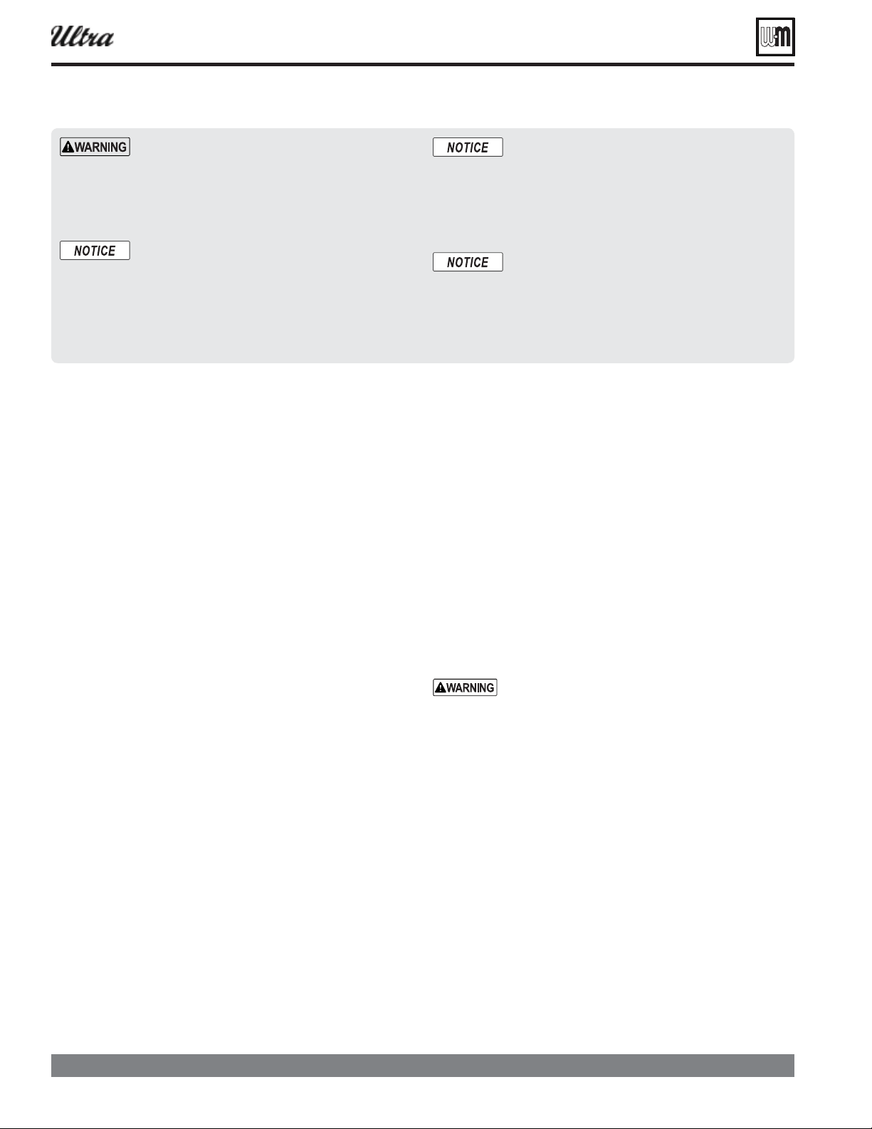
Part number 550-100-400/0119
30
Field wiring — basic system
®
Series 4
gas-fired water boiler — Boiler Manual
— For your
safety, turn off electrical power supply at service
entrance panel before making any electrical connec-
tions to avoid possible electric shock hazard. Failure
to do so can cause severe personal injury or death.
The installation must comply with: National Electrical
Code and any other national, state, provincial or local
codes or regulations. In Canada, CSA C22.1 Canadian
Electrical Code Part 1, and any local codes.
Wiring must be N.E.C. Class 1. If original wiring
as supplied with boiler must be replaced, use only
type 105 °C wire or equivalent. Boiler must be
electrically grounded as required by National Elec-
trical Code ANSI/NFPA 70 – latest edition, and/
or the Canadian Electrical Code Part I, CSA C22.1,
Electrical Code.
The boiler when installed, must be electrically bonded
to ground in accordance with the requirements of the
authority having jurisdiction or, in the absence of
such requirements, with the National Electrical Code,
ANSI/NFPA 70 – latest edition, and/or the Canadian
Electrical Code Part I, CSA C22.1, Electrical Code.
Line voltage power input
1. Provide and install a fused disconnect or service switch
(15-ampere rated recommended) as required by applicable
codes.
2. Connect minimum 15-ampere, 120 VAC power wiring
to Ultra boiler line voltage terminal strip as shown in
Figure 34, page 31 , and Figure 111, page 96 .
Wiring circulators
1. The U-Control provides for connection of up to three circula-
tors, one of which must be the boiler circulator. In addition,
you can connect a system circulator and a DHW circulator,
for examples.
. For circula-
tors with higher amp ratings, you must install a
circulator relay or starter to provide line voltage to
the circulator. For circulators rated over 2.2 amps,
connect only the circulator relay or starter coil to
the Ultra circulator terminals.
Wiring — general
1. The U-Control provides plug-in, color-coded, non-
interchangeable terminal strips for all fi eld wiring. See the
schematic diagram ( Figure 111, page 96
( Figure 112, page 97 ).
2. The U-Control provides programmable fl exibility in system
operation, allowing control of heat supply for up to three dif-
ferent heating systems. Read this manual thoroughly before
connecting the wiring to ensure trouble-free start-up and
operation.
Wiring — overview
See this and following pages for wiring information. Also
see the Advanced section of this manual for additional wir-
ing connections and options
.
Make the following connections, some of which depend on
your system and how the U-Control will be programmed.
❏
❏
❏
The U-Control can regulate the boiler for up to three
different heating systems.
❏
The boiler is shipped with an outdoor sensor, a system
supply sensor and a system return sensor. The system
supply sensor will be required for most space heating ap-
plications. The system return sensor must also be installed
when using the system supply sensor. Use of the outdoor
sensor is optional.
Locate the sensors on the system piping as shown in
Figure 4, page 11 and other piping drawings throughout
this manual.
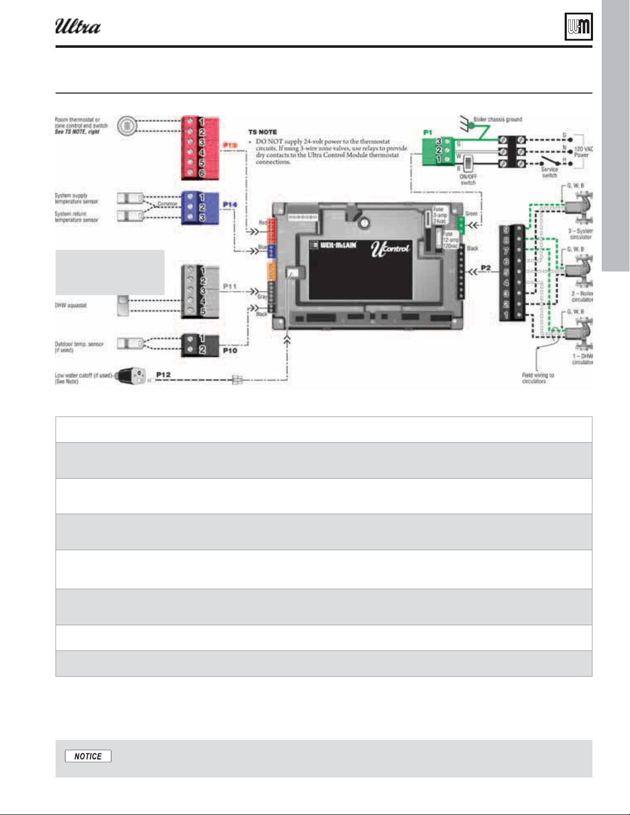
Part number 550-100-400/0119
31
Field wiring — basic system (continued)
— see the ADVANCED INSTALLATION section of this
manual.
Figure 34 Simpli ed irin asic sstem ith and space heatin see AANC section for more information
ire the tan auastat to the U-Control heat demand input terminals and .
ire the space heatin thermostat or one controller or one ale end sitches across the U-Control heat demand
input terminals and .
Attach a sensor supplied ith oiler to the sstem suppl pipe and ire to terminals and .
Locate sensor in the position shon in pipin diarams on pae throuh pae .]
Attach a sensor supplied ith oiler to the sstem return pipe and ire to terminals and .
Locate sensor in the position shon in pipin diarams on pae throuh pae .]
Install the outdoor temperature sensor supplied ith oiler and ire to terminals and .
ire the circulator supplied installer as circulator folloin instructions on Connect the oiler circulator sup-
plied ith oiler as circulator folloin instructions on pae .
ire the oiler circulator supplied ith oiler as circulator folloin instructions on pae .
ire the sstem circulator supplied installer as circulator folloin the instructions on pae .
Locate the sensors on the system
piping as shown in
Figure 4, page 11
and other piping drawings throughout
this manual.
®
Series 4
gas-fired water boiler — Boiler Manual
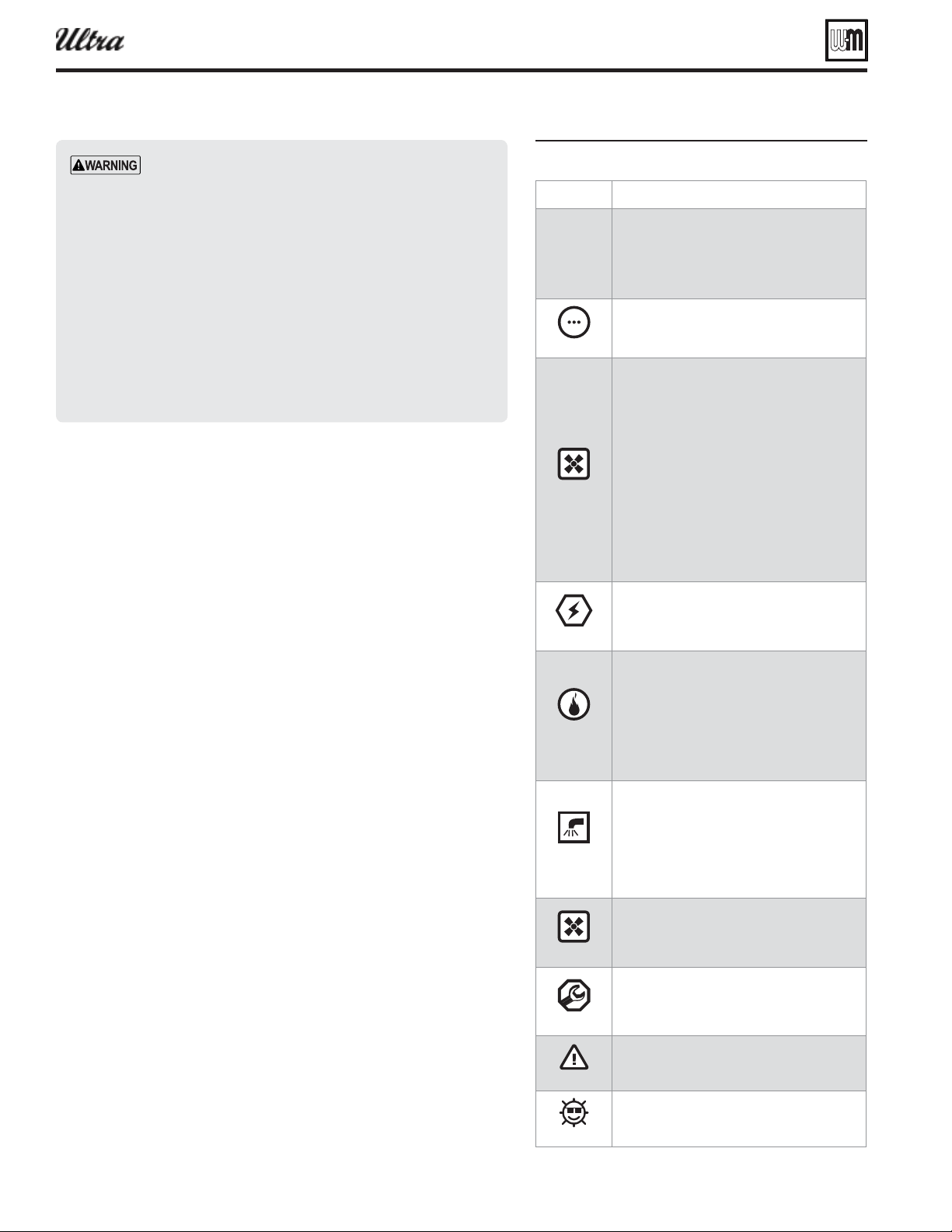
Part number 550-100-400/0119
32
U-Control operation and setup
— You must ensure that the U-
Control is set for the proper water temperatures for the
system. Excessive water temperature can cause signifi cant
property damage in some applications.
— If the heating system
includes circuits that require lower temperature water
(radiant slab circuits, for example) as well as higher
temperature circuits (DHW, fi nned tube baseboard, etc.),
it is recommended to protect low-temperature circuits
with limit controls that are wired to a U-Control external
limit circuit. Failure to provide regulation can result in
substantial property damage.
Figure 35 U-Control seuence of operation
U-Control overview
The U-Control is fully programmable to meet system requirements, allow-
ing supply water regulation for up to three different systems.
U-Control features include:
❏
Blower speed modulation to control the Ultra boiler’s fi ring rate.
❏
Advanced PID response to anticipate system needs based on response
to heat input.
❏
Graphic and robust text display for ease of operation monitoring and
troubleshooting.
❏
Preset operating parameters for typical heating systems (fi nned tube
baseboard, radiant fl oor, DHW, and others), including target tempera-
tures, reset curves and circulator assignments.
❏
Control of up to three circulators (boiler circulator plus two others),
assignable for each of the three possible inputs.
❏
Programmable priority assignments for the heat inputs.
❏
Integral outdoor reset option, with reset curves matched to the system
type selected.
❏
Multiple boiler/heat source sequencing or modulation.
❏
Built-in 0–10 VDC signal generator to allow parallel modulation of
multiple boilers; also capable of accepting 0–10 VDC input.
❏
Dual sensors for boiler outlet temperature and fl ue temperature, pro-
viding redundant protection.
❏
Integral low water protection (by monitoring boiler heat exchanger
temperature).
❏
Boiler is shipped with an outdoor sensor and strap-on system supply
and return sensors.
Sequence of operation
1. Figure 35 is a summary of the operating sequence for the U-Control.
2. The symbols shown appear in the display as the U-Control cycles the
boiler.
3. The wrench symbol appears when a scheduled maintenance date ar-
rives. This informs the homeowner to call the contractor for service.
4. The exclamation mark symbol appears when a problem has been
detected.
®
Series 4
gas-fired water boiler — Boiler Manual
(also see Figure 36, page 33 )
Check the boiler model listed on the power-up
screen. If it is not correct, turn off the boiler. See
Figure 115, page 102 to change setting.
When power is turned on, the screen lists sen-
sors that are detected. If any sensor is not listed,
make sure it is connected correctly. Turn off
power and restart.
Standby — no calls for heat
Toggles through no dots, 1 dot, 2 dots, then
3 dots while in standby (wrench symbol will
show instead if maintenance is needed)
Call for heat detected
Display on with BLUE light (space heating) or
PURPLE light (DHW)
Start min/max on timers if more than one system
is calling — highest priority starts fi rst
Start circulators for this priority setup
Calculate target temp — If sensor temp is below
target temp, begin fi ring sequence
Blower to ignition speed for prepurge
— Start
additional-heat timer — type 1 boiler starts
immediately; type 2 activates other heat source
immediately, but doesn’t start unless the timer
times out; type 3 (LEAD boiler) starts immedi-
ately and sends 0–10 VDC signal to others after
timer times out; type 4 receives signal from
LEAD boiler and starts immediately (and starts
timer for the next boiler, if programmed)
After prepurge times out, begin ignition cycle
Activate gas valve and ignition spark
Continue ignition spark for ignition period
Turn off spark and use electrode to check for
fl ame signal
Flame detected
Hold boiler at low fi re for 1 minute
Release boiler to modulation
NOTE: If fl ame is not detected, the gas valve
is turned off, blower turns on (postpurge), and
control starts cycle again. After 5 failures, the
control waits 60 minutes, then tries again.
If priority timer times out, switch to next priority
and start priority timer
If demand satisfi ed, go to postpurge
Flame detected
Release boiler to modulation immediately
NOTE: If fl ame is not detected, the gas valve
is turned off, blower turns on (postpurge), and
control starts cycle again. After 5 failures, the
control waits 60 minutes, then tries again.
If priority timer times out, switch to next priority
and start priority timer
If demand satisfi ed, go to postpurge
Demand satisfi ed (temperature reaches target
temperature or limit setting)
Gas valve off
Blower to ignition speed for postpurge
Return to standby after purge
Display turns RED, toggling between graphic
screen and maintenance screen (occurs when
maintenance schedule timer times out)
Will show during standby only
Boiler operates as normal
Display turns RED due to error or limit event
Flashing display means lockout condition —
display toggles between three screens as in
Figure 124, page 117 .
Warm weather shutdown — the boiler will not
be allowed to fi re if the outside temperature is
greater than the WWSD setting.
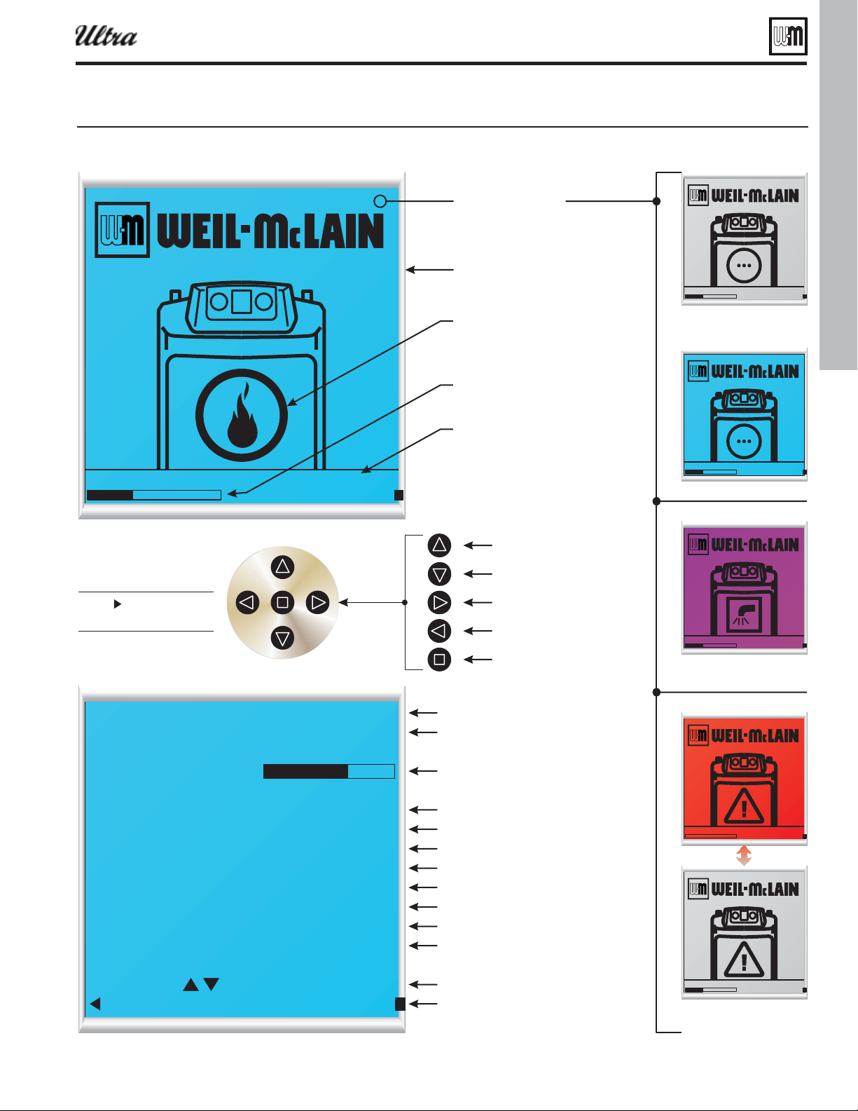
Part number 550-100-400/0119
33
U-Control operation and setup (continued)
ÊÊÊÊÊÊ "Ê
"1/" ÊÊÊ
\ÊÊÊÊÊÊÉÉ99
"1/" \
\ÊÊÊÊÊÊÉÉ99
-//1-\ÊÊÊÊÊ
/,/\ÊÊÊÊÊÊÊÊÊc
-1**9\ÊÊÊÊÊÊÊÊÊc
,/1, \ÊÊÊÊÊÊÊÊÊc
"1/"",\ÊÊÊÊÊÊÊÊc
\ÊÊÊÊÊ
*1*-\ÊÊÊÊÊÊÊÊÊÊÊÊ
¿Ê/Ê \
-// -
Ê*,6"1-ÊÊÊÊÊÊ /,Ê
1SFTTUPTXJUDIUP
*/'0TDSFFO
%JTQMBZBCPWFJTUZQJDBM
GPSOPSNBMPQFSBUJPO5IF
DFOUFSTZNCPMDIBOHFT
UPTIPXPQFSBUJPOTUBUVT
5IF*/'0TDSFFOCFMPX
JTGPSBUBHMBODFJOGPSNBUJPO
EVSJOHOPSNBMPQFSBUJPO
6
5JNFBOEEBUF
4DSFFODPMPS
#MVFTQBDFIFBUJOHPSXIFOBCVUUPOJTQSFTTFE
4DSFFOXJMMTIPXTPMJESFEXJUIUIFFYDMBNBUJPO
NBSLTZNCPMJGBOPOTIVUEPXOGBJMVSFPDDVSTJF
GBJMVSFPGBOPODSJUJDBMTFOTPSTVDIBTPVUEPPSPS
TZTUFNTVQQMZPSSFUVSOTFOTPS
4UBUVTHSBQIJD
5JNFBOEEBUF
"DUJWFTZTUFNUZQF
4VQQMZUFNQFSBUVSF
3FUVSOUFNQFSBUVSF
0VUEPPSBJSUFNQFSBUVSF
4ZTUFNTXJUI
IFBUEFNBOE
1VNQTPQFSBUJOH
0/PS0''
4FMFDUUPDIBOHFTFUUJOHT
4DSPMMVQPSEPXO
1SFWJPVTTDSFFOPS&/5&3
.PWFTFMFDUJPOVQ
/FYUTDSFFO
1SFWJPVTTDSFFO
&OUFS
.PWFTFMFDUJPOEPXO
-/ÊÊ
'JSJOHSBUF
4FUQPJOUUFNQFSBUVSF
ÊÊÊÊÊÊ "Ê
"1/" ÊÊÊÊÊÊ,/ÊÊÊ
\ÊÊÊÊÊÊÉÉ99
ÊÊÊÊÊÊ "Ê
"1/" ÊÊÊ
\ÊÊÊÊÊÊÉÉ99
ÊÊÊÊÊÊ "Ê
"1/" ÊÊÊ
\ÊÊÊÊÊÊÉÉ99
"MUFSOBUJOHDPMPST
ÊÊÊÊÊÊ "Ê
"1/" ÊÊÊ
\ÊÊÊÊÊÊÉÉ99
45"/%#:
1SFTTJOHBOZCVUUPODIBOHFT
CBDLHSPVOEUPCMVFCFMPX
ÊÊÊÊÊÊ "Ê
"1/" ÊÊÊ
\ÊÊÊÊÊÊÉÉ99
%)8)&"5*/(
%PNFTUJDIPUXBUFSIFBUJOH
#0*-&3*/-0$,065
"UUFOUJPOSFRVJSFEUP
SFTUBSUCPJMFS
#6550/4
'JSJOHSBUFCBS
0QFSBUJOHTUBUVT
"DUJWFTZTUFN
/0#"$,-*()5#-6&#"$,-*()51631-&#"$,-*()53&%#"$,-*()5/0#"$,-*()5
Figure 36 U-Control displa and naiation
(see Figure 114, page 101 )
(see Figure 114, page 101 )
®
Series 4
gas-fired water boiler — Boiler Manual
Part number 550-100-400/0119
34
U-Control operation and setup (continued)
EXPRESS SETUP — using default settings
1. The U-Control is factory programmed to supply a DHW circuit (control
priority 1) and fi nned tube baseboard space heating (control priority 2).
2. Control priority 3 is also available, and preset to run all three circulators
if desired, but requires settings to be confi gured.
Figure 37 actor default settins
1
irect
190°F Onl
2
inned
tue BB
ed if no outdoor sensor or
at outside at
outside
and
3 Custom
ed if no outdoor sensor or
at outside at
outside
None
3. You can use the factory default settings for most systems supplying
space heating with fi nned-tube baseboard with or without a DHW
tank, provided:
a. A DHW tank, if used, must be piped directly to the boiler, as in the
piping shown in Figure 5, page 12 or Figure 6, page 13 .
b. If the DHW tank is a separate zone off of the system main, or if it is
piped as in Figure 48, page 52 , you will need to enable additional cir-
culators for DHW operation. The U-Control is factory programmed
to operate only the DHW circulator during DHW heating.
c. The heat emitters in the system must be fi nned tube baseboard
only. Other heat emitters require changes in the U-Control setup.
See ADVANCED INSTALLATION section for information.
4. Wiring to use the factory default settings — see information in
Figure 34, page 31 for wiring instructions.
, see the
ADVANCED INSTALLATION
section of this manual.
(ra-
diant slab, etc.) — use
the Ultra boiler control as the only
means of water temperature regula-
tion for low-temperature systems if
higher-temperature systems are also
supplied.
®
Series 4
gas-fired water boiler — Boiler Manual
Part number 550-100-400/0119
35
Startup — fi ll the system
Antif reeze
1. Use only antifreeze listed by Weil-McLain as suitable for use
with Ultra Gas Boilers. A list of approved antifreeze products
is available at www.Weil-McLain.com.
2. See Replacement parts at the end of this manual for Weil-
McLain part numbers to obtain antifreeze through a Weil-
McLain distributor.
Use the correct amount of antifreeze
1. Determine the freezing temperature needed (to protect
against lowest likely temperature the system water will
encounter).
2. Find the antifreeze concentration by volume needed for this
temperature from the antifreeze manufacturer’s data on the
antifreeze container.
3. Add up the volume (gallons) of all system piping and com-
ponents, including the expansion tank and boiler.
a. Boiler water content is listed on page 137 .
b. Remember to include expansion tank water content.
4. Multiply this volume by the (percent) antifreeze needed to
fi nd the number of gallons of antifreeze to add.
Fill and test water system
1. Fill system only after ensuring the water meets the require-
ments of this manual.
2. Close manual and automatic air vents and boiler drain valve.
3. Fill to correct system pressure. Correct pressure will vary
with each application.
a. Typical cold water fi ll pressure for a residential system
is 12 psi.
b. Pressure will rise when boiler is turned on and system
water temperature increases. Operating pressure must
never exceed 25 psig.
4. At initial fi ll and during boiler startup and testing, check
system thoroughly for any leaks. Repair all leaks before
proceeding further.
Eliminate all system leaks. Continual fresh make -up
water will reduce boiler life. Minerals can build up
in sections, reducing heat transfer, overheating heat
exchanger, and causing heat exchanger failure.
X100 inhibitor is required
1. It is required that the Ultra boiler have Sentinel X100 added
to the system to prevent damage to the boilers’ heat exchanger.
Replacement Parts section at the end of this manual for re-
ordering information.
2. After fi lling the system as directed in these instructions, use
a caulking gun to inject the X100 inhibitor concentrate into
the system, or fi ll with the X100 in its liquid form, following
the instructions on the tube or container.
3. After adding the inhibitor to the system, allow time for the
water to circulate and mix. Then check the inhibitor level.
Add additional inhibitor if necessary.
4. See separate instructions or Weil-McLain website for sug-
gested guidelines to determine how much inhibitor to use.
Clean system to remove sediment
1. You must thoroughly flush the system (without boiler
connected) to remove sediment. The high-effi ciency heat
exchanger can be damaged by buildup or corrosion due to
sediment.
2. For zoned systems, fl ush each zone separately through a purge
valve. (If purge valves and isolation valves are not already
installed, install them to properly clean the system.)
3. Flush system until water runs clean and you are sure piping
is free of sediment.
Do not use petroleum-based cleaning or seal-
ing compounds in boiler system. Damage to
elastomer seals and gaskets in system could
occur, resulting in substantial property dam-
age.
Before fi lling the boiler and system with water,
verify the following.
Boiler corrosion can occur.
Failure to comply could result in boiler failure
or unreliable operation.
Water c hemistry
Water pH between 7.0 and 8.5
1. Maintain boiler water pH between 7.0 and 8.5. Check with
litmus paper or have chemically analyzed by water treatment
company.
2. If pH differs from above, consult local water treatment com-
pany for treatment needed.
3. DO NOT use softened water. Softened water can cause cor-
rosion.
Hardness less than 7 grains
1. Consult local water treatment companies for unusually hard
water areas (above 7 grains hardness).
Chlorine concentration must be
LESS THAN 200 ppm
1. Filling with chlorinated fresh water should be acceptable
since drinking water chlorine levels are typically less than
5 ppm.
2. Do not use the boiler to directly heat swimming pool or
spa water.
3. Do not fi ll boiler or operate with water containing chlorine
in excess of 200 ppm.
®
Series 4
gas-fired water boiler — Boiler Manual

Part number 550-100-400/0119
36
Startup — fi ll the system (continued)
Freeze protection (when used)
Follow these guidelines to prevent pos-
sibility of severe personal injury, death
or substantial property damage:
,
. Use only
freeze-prevention fl uids recommended
by Weil-McLain for application in Ultra
Boiler systems.
before installing the
new Ultra boiler.
for the fl uid used with
the boiler owner and leave a copy for
reference. The MSDS contains informa-
tion on potential hazards and fi rst aid
procedures for exposure or ingestion.
. Glycol concentration
and inhibitor levels may change over
time. Add antifreeze to increase con-
centration if necessary. Add inhibitor
as needed to bring to acceptable level,
using inhibitor test kit to verify.
When using freeze protection fl uid with
automatic fi ll,
. Freeze pro-
tection fl uid may leak before the water
begins to leak, causing concentration
to drop, reducing the freeze protection
level.
. Antifreeze moves more
sluggishly than water and can interfere
with heat transfer. At antifreeze concen-
trations higher than 50%, sludge can
develop in the boiler, potentially causing
damage to the heat exchanger.
.
Always drain and flush the system
thoroughly before fi lling with antifreeze.
Sludge, iron oxide deposits and other
sediment in the system inhibit fl ow and
can cause rapid breakdown of inhibi-
tors.
Use only antifreeze recommended by
Weil-McLain.
Weil-McLain provides information for
application of the antifreeze products
listed in this document only for use in
Weil-McLain Ultra boilers. Do not apply
these products or instructions for other
applications. Local codes may require a
backfl ow preventer or actual disconnec-
tion from city water supply.
Check/verify water chemistry
1. The system may have residual substances that could affect water
chemistry.
2. After the system has been fi lled and leak tested, verify water pH and
chlorine concentrations are acceptable.
3. Verify antifreeze concentration, when used.
4. Follow the instructions on the Sentinel test kit to sample the system
water and verify inhibitor concentration.
Check inhibitor concentration annually
1. Test the pH of a sample of system water at least annually. The pH of
the water mixture must be between 7.0 and 8.5. (Or use the Sentinel
inhibitor test kit to check concentration.)
2. If pH is outside this range (or inhibitor test kit indicates low level), the
inhibitor level may not be suffi cient to prevent corrosion.
3. Test antifreeze concentration.
Test antifreeze concentration at least annually. If concentra-
tion is low, add antifreeze or drain system and refi ll with
correct mixture.
4. Follow instructions on antifreeze container to determine the amount
of antifreeze needed. exceed 50% by volume concentration
of antifreeze.
5. Check inhibitor level after adjustments are made.
Purge air from water system
1. Connect a hose to the purge valve (see purge/drain valves, item 11, in
piping diagrams beginning on page 12 and page 52 . Route hose to an
area where water can drain and be seen.
2. Close the boiler or system isolation valve between the purge valve and
fi ll connection to the system.
3. Close zone isolation valves.
4. Open quick-fi ll valve on cold water make-up line.
5. Open purge valve.
6. One zone at a time, open the isolation valves. Allow water to run through
the zone, pushing out the air. Run until no noticeable air fl ow is present.
Close the zone isolation valves and proceed with the next zone. Follow
this procedure until all zones are purged.
7. Close the quick-fi ll water valve and purge valve and remove the hose.
Open all isolation valves. Watch that system pressure rises to correct
cold-fi ll pressure.
8. After the system has operated for a while, eliminate any residual air by
using the manual air vents located throughout the system.
9. If purge valves are not installed in system, open manual air vents in
system one at a time, beginning with lowest fl oor. Close vent when
water squirts out. Repeat with remaining vents.
10. Open automatic air vent (diaphragm-type or bladder-type expansion
tank systems only) one turn.
11. Starting on the lowest fl oor, open air vents one at a time until water
squirts out.
12. Repeat with remaining vents.
13. Refi ll to correct pressure.
®
Series 4
gas-fired water boiler — Boiler Manual
Part number 550-100-400/0119
37
Startup — fi nal checks
Check thermostat circuit(s)
1. Disconnect the two external wires connected to the boiler
thermostat terminals (see Field wiring, beginning on page 30
for terminal locations).
2. Connect a voltmeter across these two incoming wires. Close
each thermostat, zone valve and relay in the external circuit
one at a time and check the voltmeter reading across the
incoming wires.
3. There should NEVER be a voltage reading.
4. If a voltage does occur under any condition, check and correct
the external wiring. (This is a common problem when using
3-wire zone valves.)
5. Once the external thermostat circuit wiring is checked and
corrected if necessary, reconnect the external thermostat
circuit wires. Allow the boiler to cycle.
Inspect/fi ll condensate system
Inspect/check condensate lines and fi ttings
1. Inspect the condensate drain line, condensate PVC fi ttings
and condensate trap. (See page 27 for component locations.)
2. Pour water into the top of the boiler’s ½” PVC condensate
tee and check for any leaks in the condensate drain line or
fi ttings. Repair any leaks.
Fill condensate trap with water
1. Loosen the hose clamp securing the right end of the conden-
sate trap to the PVC reducing elbow (see page 27 for details).
2. Slide the trap hose end off of the elbow.
3. Fill the trap with fresh water to within an inch of the end
of the hose.
4. Replace trap hose on PVC reducing elbow and tighten the
hose clamp.
The condensate trap must be fi lled with water dur-
ing all times of boiler operation to avoid fl ue gas
emission from the condensate drain line. [Prime
the condensate trap (by pouring water into the
outlet tee while restricting fl ow in drain tube) if
boiler has been out of service for an extended pe-
riod.] Failure to fi ll the trap could result in severe
personal injury or death.
Final checks before starting boiler
❏
Read the instructions to adjust and set up the U-Control
module.
❏
Verify that the boiler model is set correctly in the U-Control,
and that it displays correctly.
❏
Verify that the boiler and system are full of water and all
system components are correctly set for operation.
❏
Fill vent condensate trap with water (by removing hose
clamp and hose at PVC reducing elbow). Replace hose on
PVC reducing elbow and tighten clamp.
❏
Verify electrical connections are correct and securely at-
tached.
❏
Inspect vent piping and air piping for signs of deteriora-
tion from corrosion, physical damage or sagging. Verify air
piping and vent piping are intact and correctly installed per
this manual.
Check for gas leaks
Before starting the boiler, and during ini-
tial operation, use a leak detector or smell
near the fl oor and around the boiler for
gas odorant or any unusual odor. Remove
boiler front door and smell interior of
boiler enclosure. Do not proceed with
startup if there is any indication of a gas
leak. Repair any leak at once.
DO NOT adjust or attempt to measure
gas valve outlet pressure. The gas valve is
factory-set for the correct outlet pressure.
This setting is suitable for natural gas and
propane, requiring no fi eld adjustment. At-
tempting to alter or measure the gas valve
outlet pressure could result in damage to
the valve, causing potential severe personal
injury, death or substantial property dam-
age.
Propane boilers only — Your propane sup-
plier mixes an odorant with the propane
to make its presence detectable. In some
instances, the odorant can fade, and the
gas may no longer have an odor. Before
startup (and periodically thereafter), have
the propane supplier verify the correct
odorant level in the gas.
®
Series 4
gas-fired water boiler — Boiler Manual
Part number 550-100-400/0119
38
To start the boiler
1. Turn OFF the boiler ON/OFF switch.
2. Read and follow the Operating Instructions,
Figure 38, page 39 .
3. The U-Control display will show installed sensors when fi rst
powered. Make sure the right sensors are detected. If not,
determine the cause and correct before proceeding.
If boiler does not start correctly
1. Check for loose connections, blown fuse or service switch
off?
2. Is external limit control (if used) open? Is boiler water tem-
perature above 200 °F?
3. Is thermostat set below room temperature?
4. Is gas turned on at meter or boiler?
5. Is incoming gas pressure less than 5” w.c. for natural gas or
4” w.c. for propane?
6. Are parameters set correctly in this manual?
7. Is the warm weather shutdown activated?
8. If none of the above corrects the problem, refer to Trouble-
shooting, beginning on page 115 .
❏ Check system and boiler
❏ Check water piping
9. Check system piping for leaks. If found, shut down boiler
and repair immediately. (See WARNING on page 35 regard-
ing failure to repair leaks.)
10. Vent any remaining air from system using manual vents. Air
in the system will interfere with circulation and cause heat
distribution problems and noise.
❏ Check vent piping and air piping
1. Check for gas-tight seal at every connection and seam of air
piping and vent piping.
Venting system must be sealed gas-tight to prevent
fl ue gas spillage and carbon monoxide emissions
which will result in severe personal injury or death.
Startup — fi nal checks (continued)
❏ Check gas piping
1. Check around the boiler for gas odor following the proce-
dure of page 29 of this manual.
If you discover evidence of any gas leak, shut
down the boiler at once. Find the leak source with
bubble test and repair immediately. Do not start
boiler again until corrected. Failure to comply
could result in severe personal injury, death or
substantial property damage.
❏ Propane boilers — verify conversion
1. Verify propane orifi ce has been installed per Propane Con-
version instructions.
DO NOT adjust or attempt to measure gas
valve outlet pressure. The gas valve is factory-
set for the correct outlet pressure. This set-
ting is suitable for natural gas and propane,
requiring no fi eld adjustment.
Attempting to alter or measure the gas valve
outlet pressure could result in damage to the
valve, causing potential severe personal injury,
death or substantial property damage.
Ultra boilers are shipped ready to fi re natu-
ral gas ONLY. Exception: The Ultra-80LP is
factory-equipped to fi re propane. You must
install the propane orifi ce if the boiler will be
connected to propane. See page 48 .
Failure to comply could result in severe per-
sonal injury, death or substantial property
damage.
®
Series 4
gas-fired water boiler — Boiler Manual
Part number 550-100-400/0119
39
Startup — fi nal checks (continued)
)25<2856$)(7<
5($'%()25(23(5$7,1*
:+$772'2,)<2860(//*$6
$7KLVDSSOLDQFHGRHVQRWKDYHD
SLORW,WLVHTXLSSHGZLWKDQ
LJQLWLRQGHYLFHZKLFK
DXWRPDWLFDOO\OLJKWVWKH
EXUQHU'RQRWWU\WROLJKWWKH
EXUQHUE\KDQG
%%HIRUH23(5$7,1*VPHOODOO
DURXQGWKHDSSOLDQFHDUHDIRU
JDV%HVXUHWRVPHOOQH[WWR
WKHIORRUEHFDXVHVRPHJDVLV
KHDYLHUWKDQDLUDQGZLOOVHWWOH
RQWKHIORRU6HHEHORZ
&8VHRQO\\RXUKDQGWRWRJJOHWKHSRZHU
VZLWFKDQGRUWXUQWKHPDQXDOJDVYDOYH
,IWKHVZLWFKRUYDOYHZLOOQRWWXUQE\
KDQGGRQWWU\WRUHSDLULWFDOODTXDOLILHG
VHUYLFHWHFKQLFLDQ)RUFHRUDWWHPSWHG
UHSDLUPD\UHVXOWLQDILUHRUH[SORVLRQ
''RQRWXVHWKLVDSSOLDQFHLIDQ\SDUWKDV
EHHQXQGHUZDWHU,PPHGLDWHO\FDOOD
TXDOLILHGVHUYLFHWHFKQLFLDQWRLQVSHFW
WKHDSSOLDQFHDQGWRUHSODFHDQ\SDUWRI
WKHFRQWUROV\VWHPDQGDQ\JDVFRQWURO
ZKLFKKDVEHHQXQGHUZDWHU
,PPHGLDWHO\FDOO\RXUJDVVXSSOLHUIURPD
QHLJKERUVSKRQH)ROORZWKHJDV
VXSSOLHUVLQVWUXFWLRQV
,I\RXFDQQRWUHDFK\RXUJDVVXSSOLHU
FDOOWKHILUHGHSDUWPHQW
'RQRWWU\WROLJKWDQ\DSSOLDQFH
'RQRWWRXFKDQ\HOHFWULF
VZLWFKGRQRWXVHDQ\SKRQHLQ
\RXUEXLOGLQJ
,I \RX GR QRW IROORZ WKHVH LQVWUXFWLRQV
H[DFWO\D ILUH RUH[SORVLRQ PD\ UHVXOW
FDXVLQJSURSHUW\GDPDJHSHUVRQDOLQMXU\
RUORVVRIOLIH
23(5$7,1*,16758&7,216
6723
5HDGWKHVDIHW\LQIRUPDWLRQDWOHIWRQWKLVODEHO7KLVDSSOLDQFHLVHTXLSSHGZLWKDQ
LJQLWLRQGHYLFHZKLFKDXWRPDWLFDOO\OLJKWVWKHEXUQHU'RQRWWU\WROLJKWWKHEXUQHUE\KDQG
6HWURRPWKHUPRVWDWVWRORZHVWVHWWLQJ
7XUQ2))DOOHOHFWULFDOSRZHUWRWKHDSSOLDQFH
7RJJOHWKHSRZHUVZLWFKORFDWHGRQ%RLOHUWR´RIIµSRVLWLRQ
/RFDWHERLOHUPDQXDOJDVYDOYHLQWKHJDVSLSLQJFRQQHFWHGWRWKHERLOHU
7XUQERLOHUPDQXDOJDVYDOYHNQREFRXQWHUFORFNZLVH¬WRRSHQJDVVXSSO\
:DLWILYHPLQXWHVWRFOHDURXWDQ\JDV7KHQVPHOOIRUJDVLQFOXGLQJQHDUWKHIORRU
,I\RXVPHOOJDV
6723
7XUQWKHERLOHUPDQXDOJDVYDOYHWR2))7KHQIROORZ
:+$772'2,)<2860(//*$6,I\RXGRQWVPHOOJDVJRWRVWHSEHORZ
7XUQ21DOOHOHFWULFDOSRZHUWRWKHDSSOLDQFHLQFOXGLQJWKHSRZHUVZLWFKORFDWHGRQ%RLOHU
6HWWKHUPRVWDWVWRGHVLUHGVHWWLQJ
7KHERLOHUGLVSOD\ZLOOVKRZV\PEROVDQGRUWH[WGHVFULELQJWKHVWDWXVRIWKHERLOHUDVLW
SURFHHGVWKURXJKLWVRSHUDWLQJVHTXHQFH6WDQGE\VWDWXVPHDQVWKHEXUQHULVRII
,IWKHDSSOLDQFHZLOOQRWRSHUDWHZKHQWKHUHLVDFDOOIRUKHDWDQGSLSLQJLVQRWKRWIROORZWKH
LQVWUXFWLRQV7R7XUQ2II*DV7R$SSOLDQFHEHORZDQGFDOO\RXUVHUYLFHWHFKQLFLDQRUJDV
VXSSOLHU
7278512))*$6727+($33/,$1&(
6HWURRPWKHUPRVWDWVWRORZHVWVHWWLQJ
7XUQ2))DOOHOHFWULFDOSRZHUWRWKHDSSOLDQFH
LQFOXGLQJWKHSRZHUVZLWFKORFDWHGRQ%RLOHU
&ORVHH[WHUQDOPDQXDOJDVFRFNYDOYHKDQGOHSHUSHQGLFXODUWRJDVSLSLQJ7XUQ
JDVYDOYHNQREFORFNZLVH¬WRFORVHJDVVXSSO\
5HSODFHERLOHUDFFHVVGRRU
0/1PTJUJPO4IPXO
(BTWBMWF
$-04&%
(BTWBMWF01&/
5ZQJDBMHBTWBMWFTIPXO
"DUVBMWBMWFNBZWBSZ
UP$-04&
UP01&/
Figure 38 Operatin instructions ANIN erif that the U-Control is set for the correct oiler model efore
proceedin.
®
Series 4
gas-fired water boiler — Boiler Manual
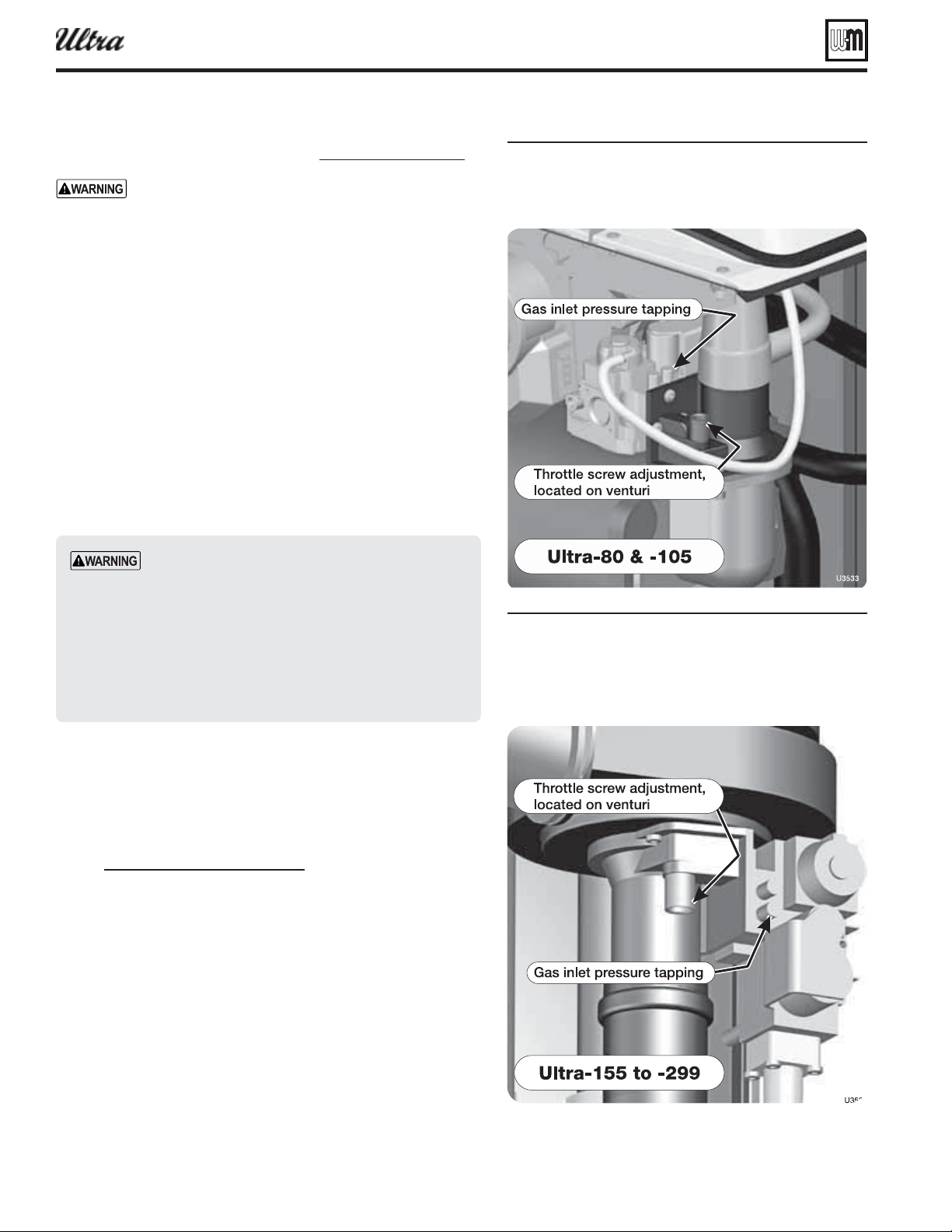
Part number 550-100-400/0119
40
Startup — fi nal checks (continued)
❏ Chec k fl ame & combustion with instruments
For Ultra-399 propane boilers, special start-up is re-
quired. See page 41 for procedure. See DANGER on
page 49 before proceeding.
1. Initiate a call for heat on one of the heat demand inputs.
2. Access the U-Control installer menus by pressing and holding the
UP and DOWN arrow keys for fi ve seconds.
3. Use the U-Control display to navigate to Manual test mode (see
Figure 115, page 102 ) and force the fi ring rate to MAX (high fi re).
4. Look at the fl ame through the fl ame inspection window. The high
fi re fl ame should be blue and should be stable. The burner surface
should be covered with orange dots.
5. Remove the fl ue temperature sensor from the fl ue pipe and in-
sert a combustion test probe., using a calibrated combustion test
instrument.
6. Test for CO
2
(or O
2
) and for CO. The CO
2
values must be within
1.0% of the values listed in Figure 42, page 41 . If results are ac-
ceptable, proceed to step 7. IF NOT, follow the instructions under
“Throttle screw adjustment procedure” to set the throttle screw
position. See WARNING below.
If combustion at either high or low fi re is outside the
range given in Figure 42 , follow the procedure given
on page 41 for adjusting the throttle screw on the
venturi. If throttle screw adjustment does not correct
the problem, then shut down the boiler and contact
your local Weil-McLain representative. Throttle
screw adjustment must be done only by a qualifi ed
technician, using calibrated test instruments. Failure
to comply could result in severe personal injury,
death or substantial property damage.
7. Measure natural gas input:
a. Operate boiler 10 minutes.
b. Turn off other appliances.
c. At natural gas meter, measure time (in seconds) required to
use one cubic foot of gas.
d. Calculate gas input:
3600 x 1000
number of seconds from step c
= Btuh
e. Btuh calculated should approximate input rating on boiler
rating label.
8. Use the U-Control display to navigate to Manual test mode (see
Figure 115, page 102 ) and force the fi ring rate to MIN (low fi re).
9. Look at the fl ame through the fl ame inspection window. The low
fi re fl ame should be stable and evenly distributed over burner
surface with a uniform orange color.
10. Repeat the combustion test of steps 4 and 5 above.
11. Use the U-Control display to navigate to Manual test mode (see
Figure 115, page 102 ) and force the fi ring rate to AUTO (normal
operation).
12. Replace the fl ue gas temperature sensor. When replacing the sen-
sor, remove the rubber grommet from the probe. Insert the rubber
grommet into the fl ue pipe, then insert the probe into the rubber
grommet.
Figure 39
®
Series 4
gas-fired water boiler — Boiler Manual
Figure 40
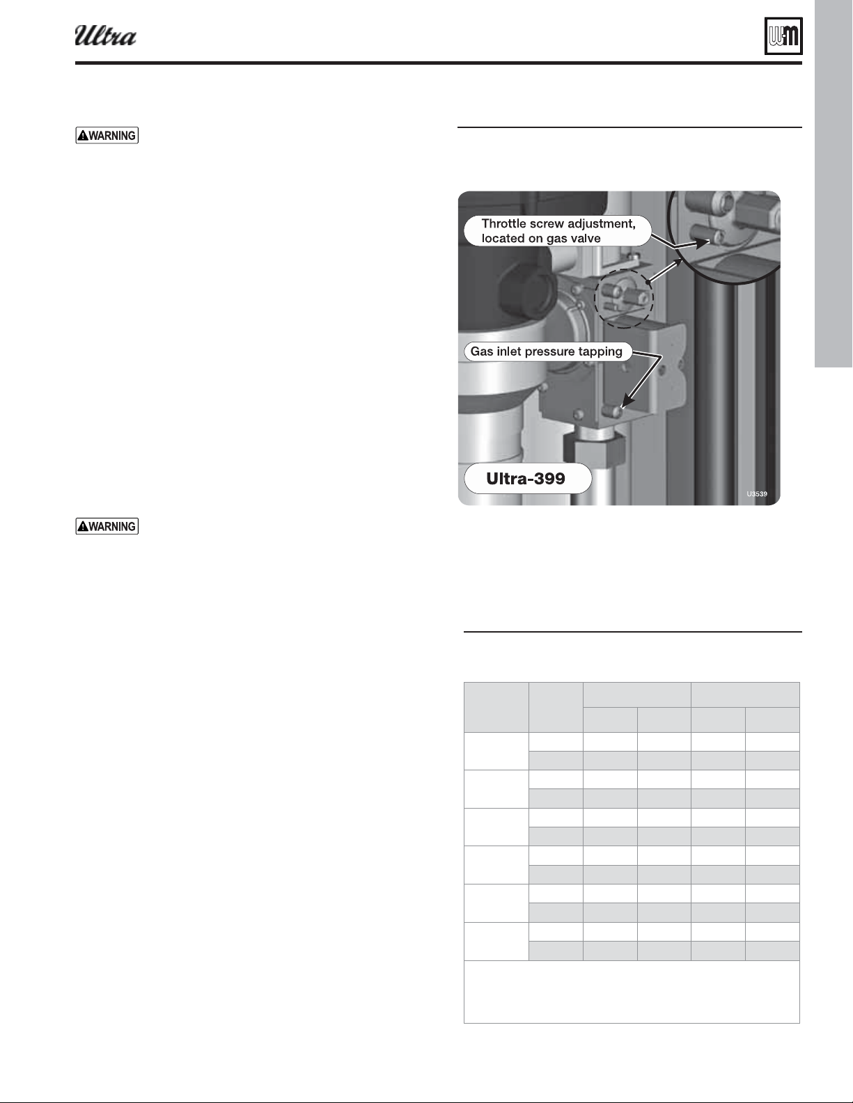
Part number 550-100-400/0119
41
Startup — fi nal checks (continued)
Figure 41
You must replace the fl ue gas temperature sensor to
prevent fl ue gas spillage into the boiler enclosure.
Failure to comply could result in severe personal
injury, death or substantial property damage.
Ultra-399 propane con version & start-up
Ultra-399 boilers are converted for propane by adjustment of the
gas valve throttle screw (no orifi ce change) — Figure 41 . This must
only be done while using a combustion analyzer.
1. Turn the gas valve throttle screw clockwise 5 turns before start-
ing the boiler. Then follow the start-up procedure on page 40 .
2. Once the boiler is started, make slight adjustments to the throttle
screw to obtain a CO
2
of 10.2% with CO less than 100 ppm air
free. (Allow the combustion analyzer’s reading to stabilize before
making adjustments.)
3. After the boiler has been set up correctly, the conversion is
complete. Fill in the information on the propane conversion
label and attach the label to the boiler rating plate.
Throttle screw adjustment procedure
See Figure 39, page 40 , Figure 40, page 40 , or Figure 41 for location
of the throttle screw.
DO NOT attempt to adjust the throttle screw unless by
a qualifi ed technician, and with the use of calibrated
combustion test instruments. Adjust the throttle
screw only as needed to meet the combustion values
given in Figure 42 .
1. This procedure is only necessary when specifi ed elsewhere in
this manual or when combustion tests indicate the need, as
explained under “❏ Check fl ame & combustion with
instruments, page 40.”
2. Boiler behavior that might indicate a need to check combustion
values at high fi re (as per page 40 ) to verify boiler is in adjust-
ment include: diffi culty igniting, poor fl ame stability at low fi re,
combustion noise or high carbon monoxide values.
3. Combustion readings must be taken at both high fi re and low
fi re. DO NOT attempt an adjustment of the throttle screw at
low fi re. Just check the combustion values.
4. Use the U-Control display to navigate to Manual test mode
(see Figure 115, page 102 ) and force the fi ring rate to MAX
(high fi re). After the boiler has had time to stabilize, take a
CO
2
reading.
a. If the CO
2
is HIGH, turn the throttle screw CLOCKWISE to
lower the input. Allow the boiler to stabilize and take another
reading. Continue until the desired CO
2
value is achieved.
b. If the CO
2
is LOW, turn the throttle screw COUNTER-
CLOCKWISE to increase the input. Allow the boiler to sta-
bilize and take another reading. Continue until the desired
CO
2
value is achieved.
5. Lock the boiler into low fi re. Check the combustion readings. If
results are acceptable at low fi re, verify high fi re readings again.
Restore fi ring rate to AUTO.
6. Consult your local Weil-McLain representative if acceptable
results cannot be obtained for both high and low fi re.
❏ Adjust and test boiler controls
1. Follow instructions in this manual to set and verify
operation of the boiler controls.
Figure 42 Acceptale CO and CO alues CO alues
must e ithin . of the alues listed
Ultra
-
NG 8.6 < 60 7.8 < 60
L 9.6 < 60 8.6 < 60
-
NG 9.0 < 60 8.4 < 60
L 10.1 < 60 9.2 < 60
-
NG 9.0 < 60 8.0 < 60
L 10.0 < 60 8.5 < 60
-
NG 9.0 < 60 8.0 < 60
L 10.0 < 60 9.0 < 60
-
NG 9.0 < 60 8.0 < 60
L 10.0 < 60 9.0 < 60
-
NG 9.2 < 100 8.4 < 60
L 10.2 < 100 10.0 < 60
The alues aoe are ith the oiler front door remoed. alues
ill tpicall increase aout . once the door is reinstalled.
The alues aoe are for altitudes up to feet. or hiher
altitudes CO
2
ma e slihtl loer and CO slihtl hiher.
®
Series 4
gas-fired water boiler — Boiler Manual
Part number 550-100-400/0119
42
Check-out/startup verifi cation
❏
Ve r i fi ed that the U-Control is set for the correct boiler model?
❏
Entered installation date and installer contact information
into U-Control?
❏
Boiler and heat distribution units fi lled with water?
❏
Water chemistry verifi ed per page 35 ?
❏
Sentinel X100 corrosion inhibitor added and water tested
to be within range?
❏
Automatic air vents, if used, open one full turn?
❏
Air purged from system?
❏
Air purged from gas piping? Piping checked for leaks?
❏
Primed condensate trap?
❏
Propane orifi ce installed for propane fi ring and propane
conversion label affi xed to jacket?
Ultra boilers are shipped ready to fire natural
gas ONLY. Exception: The Ultra-80LP is factory-
equipped to fi re propane. To fi re on propane, for
all other models, you must follow the instructions
in this manual to install the propane orifi ce or
conversion kit, or make adjustments required, if
the boiler will be connected to propane. See page 9.
Failure to comply could result in severe personal
injury, death or substantial property damage.
❏
Thermostat circuit wiring checked to ensure there are no
stray voltages?
❏
Followed Operating Instructions, Figure 38, page 39 ?
❏
Burner fl ame and combustion verifi ed per page 40 ?
❏
Ve r i fi ed control operation for space heating and DHW (if
used) per this manual?
❏
Tested additional fi eld-installed controls? — If boiler has
a low water cutoff, additional high limit or other controls,
tested for operation as outlined by manufacturer? (Boiler
should be operating and should go off when controls are
tested. Verify controls cause automatic reset lockout or
manual reset lockout as desired.)
❏
Set additional field-installed limit control(s) to system
temperature requirements? Adjusted balancing valves and
controls to provide design temperature to system?
❏
For multiple zones, adjusted for correct fl ow in each zone?
❏
Ve r i fi ed thermostat heat anticipator (if available) set prop-
erly?
❏
Cycled boiler with thermostat (and with DHW aquastat, if
installed) — Raised to highest setting and verifi ed boiler goes
through normal startup cycle? Lowered to lowest setting and
verifi ed boiler goes off?
❏
Measured natural gas input? ( page 40 )
❏
Checked incoming gas pressure by connecting manometer
to gas valve ahead of boiler? (Gas pressure must be at least
5 inches w.c. for natural gas, and 4 inches w.c. for propane,
with boiler operating at high fi re, and no more than 13 inches
w.c. with boiler operating or boiler off.)
❏
Observed several operating cycles for proper operation?
❏
Set room thermostat to desired room temperature (and
DHW aquastat, if installed, to desired DHW storage tem-
perature)?
❏
Reviewed all instructions shipped with this boiler with owner
or maintenance person?
❏
Fill in , page 140 .
❏
Fill out the warranty registration card and send to
Weil-McLain.
❏
Return instructions to envelope and give to owner or place
inside boiler housing.
Fill out start-up data on the Installation and
Service Certifi cate, page 140 .
®
Series 4
gas-fired water boiler — Boiler Manual
Part number 550-100-400/0119
43
43
®
Series 4
gas-fired water boiler — Boiler Manual
Quick view . . .
Pages
44 –47
r3FBEBCPVUCPJMFSGFBUVSFTBOEGVODUJPOT
48–49
r"MMCPJMFSTFYDFQUUIF6MUSBSFRVJSFBOPSJêDFDIBOHFUP
PQFSBUFPOQSPQBOFGPMMPXJOTUSVDUJPOT
50–51
r8BMMNPVOUJOH6MUSBCPJMFSTSFRVJSFTBTQFDJBMLJU
r'PMMPXJOTUSVDUJPOTJOUIJTTFDUJPOUPXBMMNPVOUUIFCPJMFS
52–55
rѮJTTFDUJPOQSPWJEFTBEEJUJPOBMQJQJOHTVHHFTUJPOTOPUDPWFSFE
JOUIF#"4*$TFDUJPO
r*UJODMVEFTBOBQQMJDBUJPOXJUIBOFYJTUJOHJOEJSFDUXBUFSIFBUFS
QJQFEBTB[POF
56–57
rѮJTTFDUJPOQSPWJEFTJOGPSNBUJPOPOCPJMFSIFBEMPTTWTëPX
BOEPUIFSJOGPSNBUJPOOFFEFEGPSTJ[JOH%)8QJQJOH
58–64
rѮJTTFDUJPOQSPWJEFTBQQMJDBUJPOJOGPSNBUJPOBOETVHHFTUFE
QJQJOHGPSNVMUJQMFCPJMFSTZTUFNT
66–92
r5IJTTFDUJPOQSPWJEFTJOTUBMMBUJPOJOTUSVDUJPOTGPSGPVS
BEEJUJPOBMWFOUBJSQJQJOHNFUIPETOPUDPWFSFEJOUIF
#"4*$TFDUJPOUXPTJEFXBMMDPOêHVSBUJPOTBOEUXPWFSUJDBM
DPOêHVSBUJPOT
93
r4J[FPSWFSJGZTJ[JOHPGHBTTVQQMZMJOFTXJUIUIFJOGPSNBUJPO
JOUIJTTFDUJPO
94–98
rѮJTTFDUJPOJODMVEFTXJSJOHEJBHSBNTBOEBEEJUJPOBMXJSJOH
PQUJPOTBWBJMBCMFXJUIUIF6$POUSPMNPEVMF
99–
107
rѮJTTFDUJPOQSPWJEFTBDPNQMFUFEFTDSJQUJPOPG6$POUSPM
TFUUJOHPQUJPOTBOEEJBHOPTUJDT
A AN OLLO
INSTUCTIONS IN T
BASIC INSTALLATION
SCTION IST. This
section is supplemental
information onl.
This section coers
multiple oiler sstems
and sstem tpes not
coered under the BASIC
section. It also includes
alternatie entair pipin
methods ater and as
pipe siin uidelines
and adanced detailed
information on the
U-Control and oiler
irin.

Part number 550-100-400/0119
44
The Gas-fi red water boilerFeaturing Flexibility
Ultra Models -80, -105 , -155 and -230
The advanced blower design and air inlet silencer on Ultra boilers
result in very quiet operation.
the air intake adapter (18), fl ows through the enclosure, enters the
air inlet silencer (5), then enters the blower. The blower pulls air
through the silencer and pushes it into the venturi (6), where it mixes
with gas before entering the burner.
the air intake adapter (18), fl ows through the enclosure, enters the
air inlet silencer (5), then enters the venturi (6). The blower pulls air
and gas through the venturi and pushes the mixture into the burner.
The automatic gas valve (4a) senses the vacuum in the venturi
caused by fl owing air, and allows gas to fl ow when power is applied.
Models 80 and 105 use a sensing line (4c) from the gas valve to the
blower outlet so the gas valve references the same pressure as the
venturi inlet.
The horn-shaped air inlet silencer signifi cantly reduces fan noise,
providing exceptionally quiet operation.
When air fl ows through the venturi, it creates a vacuum. This vacuum
pulls gas from the gas valve. So gas will only fl ow if air is fl owing.
On model 80 and 105, the gas/air mixture enters the burner after
the venturi. On models 155 and 230, the gas/air mixture enters the
blower before passing on to the burner.
This sensor monitors boiler outlet water temperature. The control
module adjusts boiler fi ring rate so the outlet temperature is correct,
based on boiler outlet and system supply temperatures.
This sensor monitors return water temperature. The control module
reduces or increases boiler input, depending on how close the return
water temperature is to the outlet water temperature.
The electronic display is used to confi gure boiler settings and moni-
tor boiler operation.
The buttons allow changing display mode, entering setting values,
and resetting after lockout.
Made with high-grade stainless steel construction, the burner uses
pre-mixed air and gas. The burner and control provide modulat-
ing fi ring.
U-Control
The
U-Control
odule responds to signals from the room ther-
mostats, DHW aquastats (when used), boiler sensors (boiler return,
boiler supply, system return, system supply, fl ue temperature, and
outdoor temperature, if used). The control module automatically
adjusts blower speed (and gas fl ow rate) to match boiler output to
space heating and/or DHW heating demand.
The Ultra control panel is mounted to a hinged sub panel, allow-
ing the panel to be swung forward and down for easy access to the
electrical connections.
The air intake adapter incorporates an internal drain on models 80
and 105.
Knockouts are provided in the jacket top panel, allowing conduit
entry directly behind the control panel or near the wall.
Connect the boiler internal condensate trap line to the heat ex-
changer here (parts supplied with boiler, but fi eld installed).
The condensate trap PVC fi ttings are fi eld-installed, connected to
the condensate trap line as shown in this manual.
The front door is sealed to the boiler assembly around its entire
perimeter.
Two (2) screws secure the door in place.
The burner fl ame is ignited by applying a high voltage to the igni-
tion electrode. This causes a spark (from electrode to ground). After
ignition, the electrode measures fl ame signal.
The quartz glass window provides a view of the burner surface
and fl ame.
This dual sensor monitors the fl ue gas exit temperature. The control
module will shut down the boiler if fl ue gas temperature gets too hot.
This protects the fl ue pipe and the heat exchanger from overheating.
®
Series 4
gas-fired water boiler — Boiler Manual
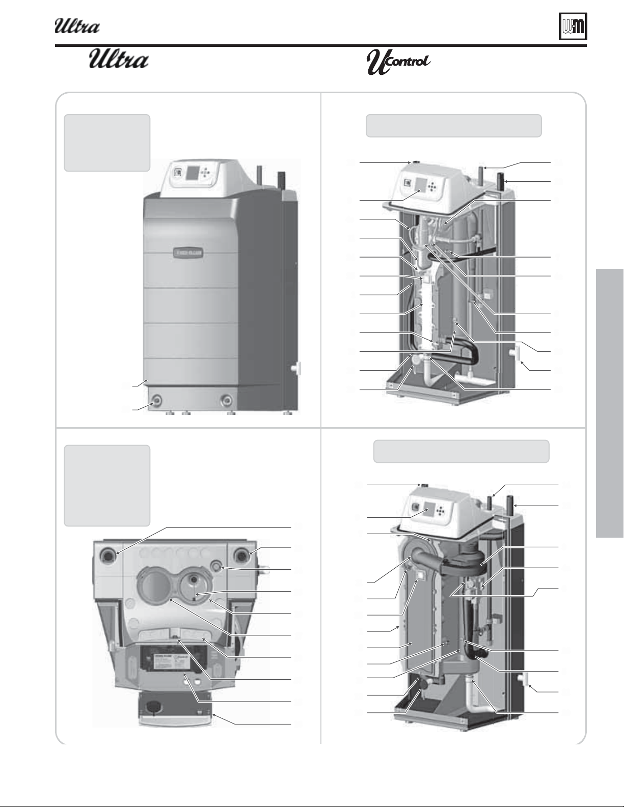
Part number 550-100-400/0119
45
'SPOUWJFX
BMMNPEFMT
8
6MUSB
GSPOUEPPSSFNPWFE
5PQWJFX
BMMNPEFMT
5PQJTTIPXOXJUIUPQDPWFS
SFNPWFEBOEDPOUSPMQBOFM
TXVOHEPXOGPSFBTZ
BDDFTTUPXJSJOHUFSNJOBMT
B
D
6MUSB
GSPOUEPPSSFNPWFE
B
BUTVQQMZQJQFFYJU
The Gas-fi red water boilerFeaturing Flexibility
®
Series 4
gas-fired water boiler — Boiler Manual

Part number 550-100-400/0119
46
The Gas-fi red water boilerFeaturing Flexibility
Ultra Models -299/310 and -399
The advanced blower design and air inlet silencer on Ultra boilers
result in very quiet operation.
Air enters the boiler enclosure through the air intake adapter (18),
fl ows through the enclosure, enters the air inlet silencer (5), then
enters the venturi (6). The blower pulls air and gas through the
venturi and pushes the mixture into the burner.
The automatic gas valve (4a) senses the vacuum in the venturi caused
by fl owing air, and allows gas to fl ow when power is applied. The
manual gas valve (4b) allows shutting off the gas supply for servic-
ing or shutdown.
The horn-shaped air inlet silencer signifi cantly reduces fan noise,
providing exceptionally quiet operation.
When air fl ows through the venturi, it creates a vacuum. This vacuum
pulls gas from the gas valve. So gas will only fl ow if air is fl owing. The
gas/air mixture enters the blower before passing on to the burner.
This sensor monitors boiler outlet water temperature. The control
module adjusts boiler fi ring rate so the outlet temperature is correct,
based on boiler outlet and system supply temperatures.
This sensor monitors return water temperature. The control module
reduces or increases boiler input, depending on how close the return
water temperature is to the outlet water temperature.
The electronic display is used to confi gure boiler settings and moni-
tor boiler operation.
The buttons allow changing display mode, entering setting values,
and resetting after lockout.
Made with high-grade stainless steel construction, the burner uses
pre-mixed air and gas. The burner and control provide modulat-
ing fi ring.
U-Control
The U-Control
odule responds to signals from the room ther-
mostats, DHW aquastats (when used), boiler sensors (boiler return,
boiler supply, system return, system supply, fl ue temperature, and
outdoor temperature, if used). The control module automatically
adjusts blower speed (and gas fl ow rate) to match boiler output to
space heating and/or DHW heating demand.
The Ultra control panel is mounted to a hinged sub panel, allow-
ing the panel to be swung forward and down for easy access to the
electrical connections.
Knockouts are provided in the jacket top panel, allowing conduit
entry directly behind the control panel or near the wall.
Connect the boiler internal condensate trap line to the heat ex-
changer here (parts supplied with boiler, but fi eld installed).
The condensate trap PVC fi ttings are fi eld-installed, connected to
the condensate trap line as shown in this manual.
The front door is sealed to the boiler assembly around its entire
perimeter.
Two (2) screws secure the door in place.
The burner fl ame is ignited by applying a high voltage to the igni-
tion electrode. This causes a spark (from electrode to ground). After
ignition, the electrode measures fl ame signal.
The quartz glass window provides a view of the burner surface
and fl ame.
This dual sensor monitors the fl ue gas exit temperature. The control
module will shut down the boiler if fl ue gas temperature gets too hot.
This protects the fl ue pipe and the heat exchanger from overheating.
®
Series 4
gas-fired water boiler — Boiler Manual
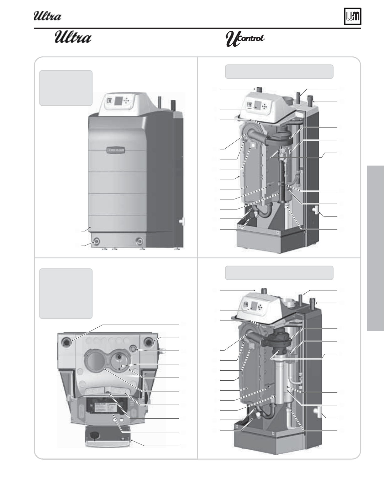
Part number 550-100-400/0119
47
5PQWJFX
BMMNPEFMT
5PQJTTIPXOXJUIUPQDPWFS
SFNPWFEBOEDPOUSPMQBOFM
TXVOHEPXOGPSFBTZ
BDDFTTUPXJSJOHUFSNJOBMT
8
6MUSB
GSPOUEPPSSFNPWFE
CFIJOETJMFODFS
B
BUTVQQMZQJQFFYJU
'SPOUWJFX
BMMNPEFMT
6MUSB
GSPOUEPPSSFNPWFE
CFIJOETJMFODFS
B
BUTVQQMZQJQFFYJU
The Gas-fi red water boilerFeaturing Flexibility
®
Series 4
gas-fired water boiler — Boiler Manual
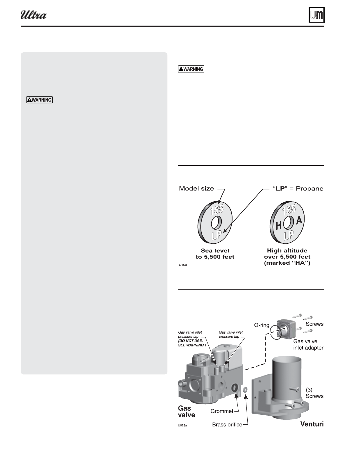
Part number 550-100-400/0119
48
Prepare boiler — convert for propane
Installing propane orifi ce
— You must turn
off electrical supply to the boiler and close the
external manual gas shut-off valve to isolate the
boiler during conversion. Allow the boiler to cool
if it has been operating. Following conversion of
an installed boiler, follow all instructions in this
manual to start up the boiler and verify operation
of the boiler and all system components.
1. Locate propane orifi ce disc from conversion kit bag.
2. Verify that the stamping on the orifi ce disk matches the model
size (see Figure 43 ).
3. With the new boiler on its back, remove jacket front door by
removing two (2) screws at lower front.
Figure 43 Ori ce identi cation
Figure 44 Installin propane ori ce
Ultra- or Ultra-L ONL
®
Series 4
gas-fired water boiler — Boiler Manual
Prepa re boiler for propane
(when required)
Propane operation
. Propane-ready boilers
have suffi x “LP” after the model number. All
other boilers require conversion for propane
operation.
natural gas boilersrequire instal-
lation of a burner in addition to an orifi ce
change. use the instructions in this
manual for these boilers. Use only the instruc-
tions included in the special-order conversion
kits.
— For a boiler already
installed, you must turn off gas supply, turn
off power and allow boiler to cool before
proceeding. You must also completely test the
boiler after conversion to verify performance
and start up the boiler following instructions
beginning on page 35 of this manual.
— For instal-
lations more than 5,500 feet above sea level,
obtain the high altitude propane orifi ce kit..
— See Figure 43 . Verify
when installing that the orifi ce size marking
matches boiler size. Use only the special-order
orifi ce for altitudes above 5,500
feet.
–– Sea level (to 5,500 feet), Part number 540-
202-833, Assembly Bag Orifi ce Gas Ultra 310
Canada supplied with boiler.
–– High altitude (above 5,500 feet), Part num-
ber 383-500-648, Kit Conversion Liquefi ed
Petroleum (Propane) Gas Ultra 310 - special
order.
Failure to comply could result in severe per-
sonal injury, death or substantial property
damage.
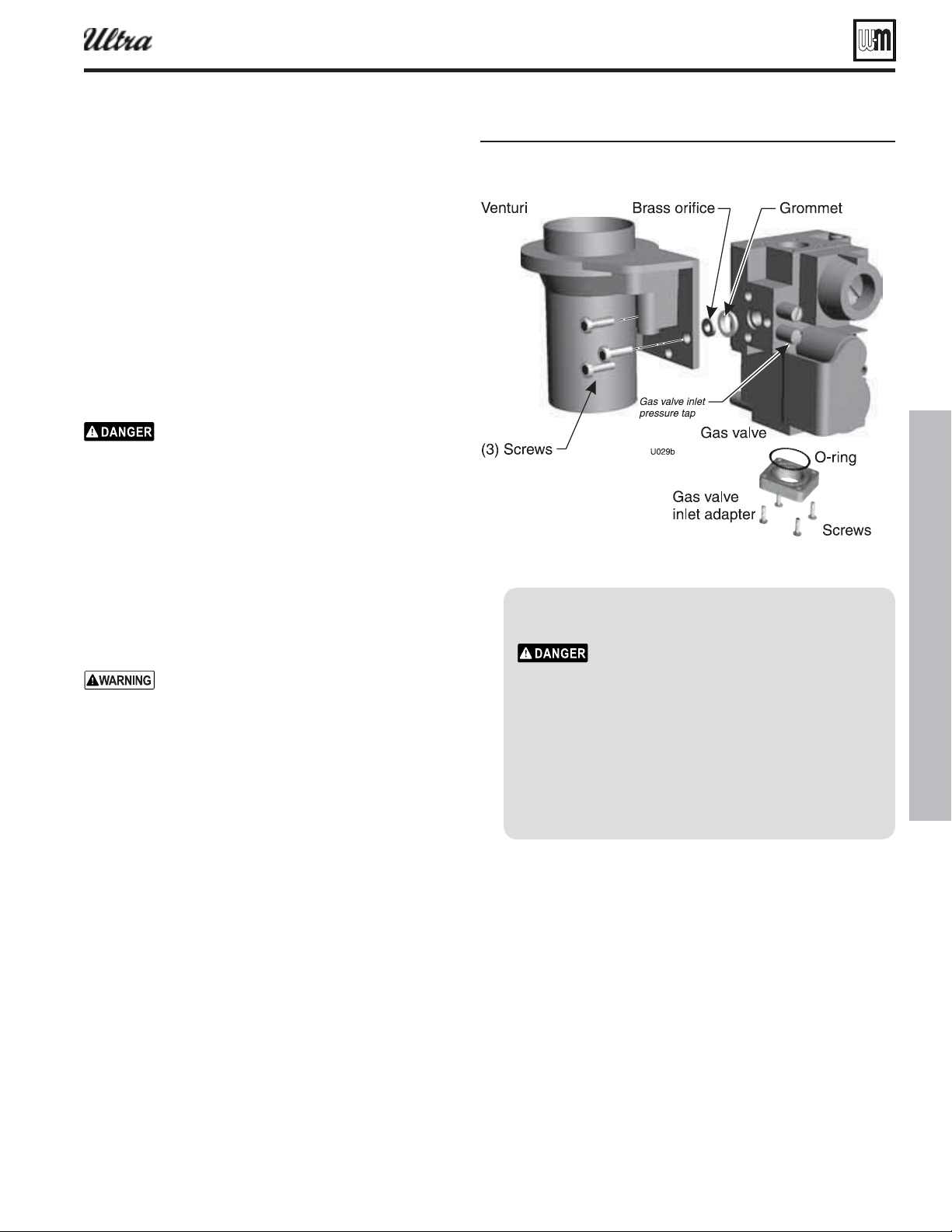
Part number 550-100-400/0119
49
4. Lift the door away from boiler.
5. Remove the air inlet silencer from the adapter:
a. Models 80 and 105: See Figure 134, page 133 .
b. Models 155 and 230: See Figure 135, page 134 .
c. Models 299/310 and 399: See Figure 136, page 135 .
6. Disconnect the gas valve electrical plug.
7. See Figure 43, page 48 or Figure 45 . Remove the 4 screws
securing gas valve inlet adapter to valve.
8. Use a 5mm wrench to remove the three Allen-head screws
securing the gas valve to the venturi ( Figure 43, page 48
or Figure 45 ).
9. Place orifi ce in the black rubber grommet in the side of
the gas valve and secure in valve ( Figure 43, page 48 or
Figure 45 ).
See Figure 43, page 48 or Figure 45 . Inspect the
O-ring between the gas valve and gas valve inlet
adapter whenever they are disassembled. The
O-ring must be in good condition and must be
installed. Failure to comply will cause a gas leak,
resulting in severe personal injury or death.
10. Reposition gas valve against venturi and replace (3) Allen-
head screws securing valve to venturi ( Figure 43, page 48
or Figure 45 ).
11. See Figure 43, page 48 or Figure 45 . Secure gas valve inlet
adapter to gas valve with 4 screws. Make sure the plastic
hose is connected from gas valve to inlet elbow on Ultra-80
and -105.
The valve could be dam-
aged by manometer fl uid contamination. Failure
to comply could result in severe personal injury,
death or substantial property damage.
12. Connect gas valve electrical plug to valve terminals.
13. Re-attach the air inlet silencer.
14. After installation is complete, attach the propane conver-
sion label (in conversion kit bag) next to the boiler rating
plate.
15. Replace jacket front panel.
Figure 45Installin propane ori ce Ultra- - -
®
Series 4
gas-fired water boiler — Boiler Manual
Ultra-399 boilers
Ul tra-399 boilers are converted for propane by
adjustment of the gas valve throttling screw.
See instructions on page 41 of this manual.
Do not perform the propane conversion of
an Ultra-399 boiler without using a fl ue gas
analyzer. The proper use of a fl ue gas analyzer
is required to determine proper gas valve set-
tings. Improper gas valve settings can cause
severe personal injury, death or substantial
property damage.
Prepare boiler — convert for propane (continued)
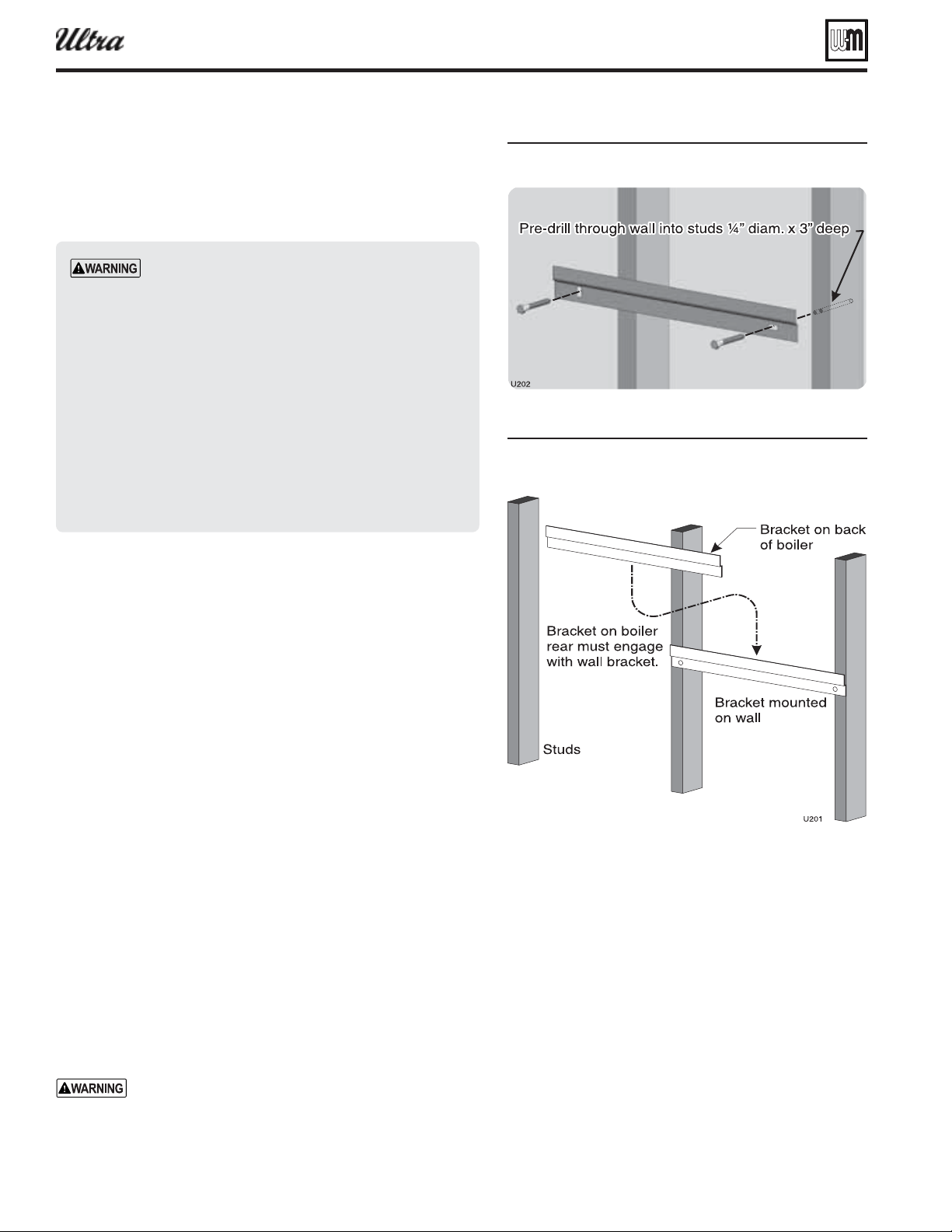
Part number 550-100-400/0119
50
Placing boiler — wall-mounting option
Figure 46Install all-mount racet
Figure 47lace oiler on all-mount racet
®
Series 4
gas-fired water boiler — Boiler Manual
Wall-mounted boilers (Ultra-80 through -399)
1. The wall-mounting kit is NOT supplied as standard equipment
with the boiler, and must be purchased separately. See
below.
Wall mount Ultra boilers only using the Weil-
McLain Ultra boiler wall-mounting kit and accom-
panying instructions. (See Repair parts section for
part number of wall mounting kit.) DO NOT use
the shipping bracket to wall mount the boiler.
The wall must be vertically plumb and capable of
carrying the weight of the boiler. The operating
weights for wall-mountable boilers are:
Ultra-80: 139 pounds Ultra-105: 145 pounds
Ultra-155: 181 pounds Ultra-230: 192 pounds
Ultra-299/310: 229 pounds U lt r a -3 9 9: 22 9
pounds
Failure to comply with above and the procedure
given below could result in severe personal injury,
death or substantial property damage.
2. Verify kit contents:
a. Wall-mount bracket.
b. Black iron bushing, 1” x 1/8” NPT.
c. Lag screws, (2) 3/8” x 3” hex head.
d.
e. Automatic air vent, 1/8” NPT.
f. Items b through e are needed only if routing piping through
bottom of enclosure (applies only for Ultra-80 through -230).
g. Verify all parts listed above are available before proceeding.
3. Stud spacing: Bracket holes are spaced for studs on 16-inch centers.
For other stud spacing, provide secure, solid mounting surface on
which to attach the boiler wall-mounting bracket.
4. Wood stud wall: Install bracket with lag screws (3/8” x 3”) included
in kit, only into the studs.
5. Metal stud wall: Secure bracket to studs with 3/16-inch toggle bolts
and 3/16-inch fl at washers (not included with kit).
attempt to attach the wall mount bracket using anchors
or any means other than directly securing to the wall studs (or
equivalent wood structure if studs are not on 16-inch centers).
7. The boiler bracket must engage with the wall-mount bracket. Make
sure the brackets are not just resting edge to edge.
8. Mount the boiler on the wall following these instructions. Perform
all procedures given in the Boiler Manual on pages 1 through 9
before mounting the boiler.
The boiler is heavy. Use caution not to drop the boiler
or cause bodily injury while lifting and handling. Verify
that the boiler is securely attached to prevent possibility
of boiler falling after installation.

Part number 550-100-400/0119
51
®
Series 4
gas-fired water boiler — Boiler Manual
Prepare boiler for wall mounting
1. Remove the jacket front panel. This will simplify lifting and han-
dling the boiler when mounting.
2. When piping will be routed out the top of the boiler, no special
preparation is needed other than that given in this manual.
Install wall-mount bracket
1. Locate studs.
2. Place the wall-mount bracket on the wall, using a level to align
correctly.
3. Place the bracket so the mounting slots are centered over the studs.
4. Level the bracket and trace the outline of the screw slots with a
pencil.
5. Remove bracket and drill holes 1/4” diameter by 3 inches deep,
centered on the screw slot outlines. (For metal stud walls, using
3/16” toggle bolts, drill required clearance holes.)
6. See Figure 47, page 50 . Position bracket on wall. Insert and loosely
tighten the two lag screws (or toggle bolts for metal studs).
7. Level the bracket. Then tighten screws securely. For drywall or
plaster lathe installations, avoid tightening so much that brackets
dig into wall surface.
Place boiler on bracket
1. Measure 30
3
/
4
inches below the bottom edge of the wall-mount
bracket for Ultra-80 to -230 (35
5
/
8
” for Ultra-299/310/399). Strike
a line or place a piece of masking tape on the wall with its top
edge even with the 30-inch mark. (This line, or tape, will indicate
whether the boiler has been properly seated onto the wall-mount
bracket.)
2. Obtain assistance to lift the boiler into position:
a. Lift the boiler high enough that its rear bracket will be above
the wall-mount bracket.
b. Let the rear of the boiler slide against the lag screw heads as
you lower the boiler into place.
c. When the brackets are engaged correctly, the bottom of the
boiler enclosure will be at or near the pencil line, or tape, you
applied in step 1.
d. If the boiler does not slide down close to the mark, or tape,
adjust until the brackets properly engage.
Placing boiler — wall-mounting option (continued)
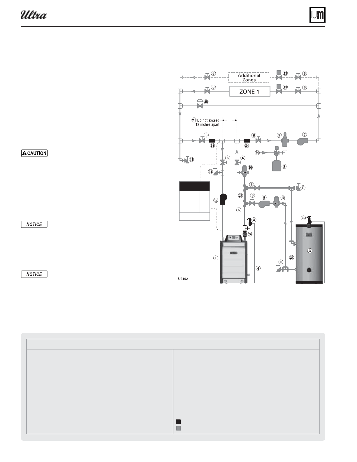
Part number 550-100-400/0119
52
Legend — Figure 48
1 Ultra boiler
2 Indirect water heater (DHW), if used
3 Boiler relief valve (see page 9 for piping details)
4 Relief valve discharge piping (see page 9 for details)
5 DHW circulator (see page 56 for suggested sizing)
6 Isolation valves
7 System circulator (see information above for wiring)
8 Diaphragm (or bladder) type expansion tank (see page 56 for piping of
closed-type expansion tank, if used)
9 Air separator [with automatic air vent only on systems using diaphragm
(or bladder) type expansion tank]
10 Flow/check valves
11 Purge/drain valves
12 Boiler circulator
13 Zone valves, typical
20 Make-up water supply
21 Primary/secondary connection (tees no more than 12 inches apart)
23 DHW supply/return
24 Strap system supply and return sensors to lines as shown, at least 6 pipe
diameters (but no more than 3 feet) from boiler connection tees.
25 Systems using high-head pumps may require a bypass pressure regulator
to prevent damage to control valves.
26 Temperature/Pressure gauge
27 DHW relief valve, if used
Items supplied with boiler
Items supplied by others
Install water piping — advanced
Figure 48one ale onin plus optional pipin
Zoning with zone valves
(alternate to piping shown in Figure 5, page 12 )
High-fl ow-rate/high-head-loss DHW
circuits
1. For applications requiring DHW circuit fl ow rates higher than
allowable for the boiler, or for high pressure-drop coil-type
DHW tanks, connect the piping as in Figure 48 . The DHW
water only fl ows through the secondary circuit connector pip-
ing. NOTE: Make sure to size the connector piping ( Figure 48 ,
item 23) to handle the total fl ow it must handle.
2. Connect boiler to system as shown in Figure 48 when zone
valve zoning. The primary/secondary piping shown ensures
the boiler loop will have suffi cient fl ow. It also avoids apply-
ing the high head of the boiler circulator to the zone valves.
Use the pipe size shown in Fig-
ure 48 on all boiler loop piping (connecting boiler
to and from the primary/secondary connection,
item 21).
Failure to follow these guidelines could
result in system problems.
3. When using a closed-type expansion tank, connect the
expansion tank and make-up water piping as shown in
Figure 4, page 11 .
4. Connect DHW (domestic hot water) piping to indirect stor-
age water heater as shown.
By default, the U-Control Module turns off space
heating during DHW heating (if DHW input is
priority 1). The boiler circulator will turn off, pre-
venting hot water from circulating to the system
(optional timeout setting can be used to override).
The fl ow/check valve shown on the boiler outlet
piping prevents gravity circulation in the boiler
loop during DHW heating.
Overriding the Outdoor Reset function by setting control
to DHW mode when system is intended for space heat-
ing may violate Section 303 of the 2007 Energy Act. See
page 137 for compliance information and exemptions.
5. Controlling the system circulator and boiler circulator
a. You will have to set up the U-Control to operate both the
boiler circulator and the DHW circulator during DHW
operation. The system circulator should be off during
DHW heating. Read the instructions on U-Control op-
eration and setup, beginning on page 32 .
®
Series 4
gas-fired water boiler — Boiler Manual
Boiler loop pipe size
Ultra-80, 105
Ultra-155, 230
Ultra-299/310,
399
1”
1¼”
1½”
See CAUTION at left.
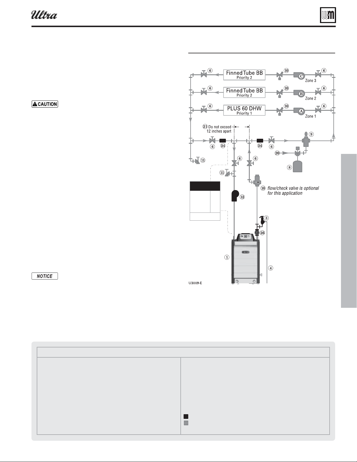
Part number 550-100-400/0119
53
Install water piping — advanced (continued)
Legend — Figure 49
1 Ultra boiler
2 Indirect water heater (DHW), if used
3 Boiler relief valve (see page 9 for piping details)
4 Relief valve discharge piping (see page 9 for details)
6 Isolation valves
8 Diaphragm (or bladder) type expansion tank (see page 56 for piping of
closed-type expansion tank, if used)
9 Air separator [with automatic air vent only on systems using diaphragm
(or bladder) type expansion tank]
10 Flow/check valves
11 Purge/drain valves
12 Boiler circulator
20 Make-up water supply
21 Primary/secondary connection (tees no more than 12 inches apart)
24 Strap system supply and return sensors to lines as shown, at least 6 pipe
diameters (but no more than 3 feet) from boiler connection tees.
26 Temperature/Pressure gauge
Items supplied with boiler
Items supplied by others
Figure 49Circulator onin plus optional pipin
Example system with DHW as a zone,
zoning with circulators
1. Connect boiler to system as shown in Figure 49 when circula-
tor zoning. The boiler circulator cannot be used for a zone.
It must supply only the boiler loop. Also see the information
on page 10 for suggested piping and sizing.
Use the pipe size shown in
Figure 49 on all boiler loop piping (connecting
boiler to and from the primary/secondary connec-
tion, item 21).
Failure to follow these guidelines
could result in system problems.
2. Install a separate circulator for each zone.
3. DO NOT use a closed-type tank with a AQUA PLUS water
heater in the system. The automatic air vent required on the
water heater will deplete air in the system, causing the expan-
sion tank to waterlog. Use only a diaphragm- or bladder-type
tank, suitable for automatic air vent applications.
4. In this example, the AQUA PLUS 60 DHW tank is piped as
a zone in the system, with piping connections to the tank in
accordance with the AQUA PLUS manual.
5. Wiring to the U-Control
a. Priority 1 = AQUA PLUS 60 (zone 1): wire AQUA PLUS
60 aquastat terminals to U-Control P11, pins 4 and 5.
Wire DHW circulator, A, to U-Control P2, terminals 1,
4 and 7 (H, N, G).
b. Wire zone pumps B and C to a two-zone circulator relay.
c. Priority 2 = fi nned-tube baseboard (zones 2 and 3): wire
circulator relay end switch 1 to U-Control P15, pins 1
and 2.
6. Make sure to set Priority 1 to DHW system, not DHW direct.
Overriding the Outdoor Reset function by setting control
to DHW mode when system is intended for space heat-
ing may violate Section 303 of the 2007 Energy Act. See
page 137 for compliance information and exemptions.
7. Controlling the system circulator and boiler circulator
a. You will have to set up the U-Control to operate both the
boiler circulator and the DHW circulator during DHW
operation. Read the instructions on U-Control operation
and setup, beginning on page 32 .
®
Series 4
gas-fired water boiler — Boiler Manual
Boiler loop pipe size
Ultra-80, 105
Ultra-155, 230
Ultra-299/310,
399
1”
1¼”
1½”
See CAUTION at left.
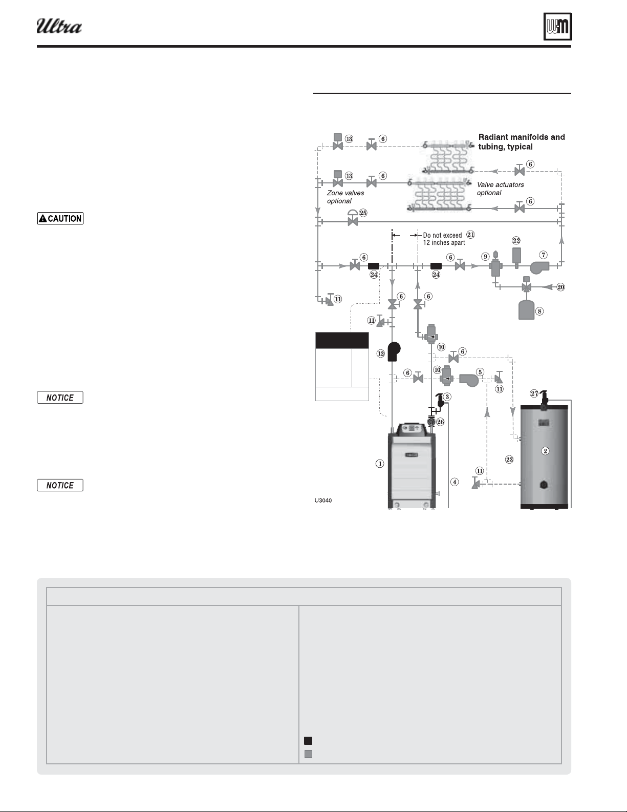
Part number 550-100-400/0119
54
Legend — Figure 50
1 Ultra boiler
2 Indirect water heater (DHW), if used
3 Boiler relief valve (see page 9 for piping details)
4 Relief valve discharge piping (see page 9 for details)
5 DHW circulator (see page 56 for suggested sizing)
6 Isolation valves
7 System circulator (see information above for wiring)
8 Diaphragm (or bladder) type expansion tank (see page 56 for piping of
closed-type expansion tank, if used)
9 Air separator [with automatic air vent only on systems using diaphragm
(or bladder) type expansion tank]
10 Flow/check valves
11 Purge/drain valves
12 Boiler circulator
13 Zone valves, when used (zoning may also be done using manifold-mounted
valve actuators)
20 Make-up water supply
21 Primary/secondary connection (tees no more than 12 inches apart)
22 Optional high limit temperature control, set to protect radiant tubing
23 DHW supply/return
24 Strap system supply and return sensors to lines as shown, at least 6 pipe
diameters (but no more than 3 feet) from boiler connection tees.
25 Systems using high-head pumps may require a bypass pressure regulator
to prevent damage to control valves.
26 Temperature/Pressure gauge
27 DHW relief valve, if used
Items supplied with boiler
Items supplied by others
Figure 50Tpical radiant heatin sstem pipin plus
optional
Radiant heating applications
1. The Ultra boiler is ideal for use in radiant heating. The Ultra
boiler’s unique heat exchanger design allows it to work well
even in condensing mode. So there is no need to regulate boil-
er return water temperature in radiant heating applications.
2. Connect boiler to system as shown in Figure 50 for typical
radiant heating applications. The primary/secondary piping
shown ensures the boiler loop will have suffi cient fl ow. Size
the system piping and circulator to provide the fl ow and
pressure drop needed for the radiant system.
Use the pipe size shown in Fig-
ure 50 on all boiler loop piping (connecting boiler
to and from the primary/secondary connection,
item 21).
Failure to follow these guidelines could
result in system problems.
3. Adding the recommended high limit control ( Figure 50 ,
item 22) can help ensure supply water temperature will not
exceed the maximum allowable for the radiant system. Wire
this limit control in either the manual reset or automatic reset
external limit circuit of the U-Control.
4. When using a closed-type expansion tank, connect the
expansion tank and make-up water piping as shown in
Figure 4, page 11 .
5. Connect DHW (domestic hot water) piping to indirect stor-
age water heater as shown.
By default, the U-Control Module turns off space
heating during DHW heating (if DHW input is
priority 1). The boiler circulator will turn off, pre-
venting hot water from circulating to the system
(optional timeout setting can be used to override).
The fl ow/check valve shown on the boiler outlet
piping prevents gravity circulation in the boiler
loop during DHW heating.
Overriding the Outdoor Reset function by setting control
to DHW mode when system is intended for space heat-
ing may violate Section 303 of the 2007 Energy Act. See
page 137 for compliance information and exemptions.
6. Controlling the circulators
a. The U-Control can control up to three circulators (boiler
circulator and two others). Refer to Field wiring, begin-
ning on page 30 , for instructions on wiring to circulators.
Install water piping — advanced (continued)
b. The factory default settings are: DHW circulator as Circu-
lator 1, boiler circulator as Circulator 2. See Field wiring
instructions, beginning on page 30 , for details.
®
Series 4
gas-fired water boiler — Boiler Manual
Boiler loop pipe size
Ultra-80, 105
Ultra-155, 230
Ultra-299/310,
399
1”
1¼”
1½”
See CAUTION at left.
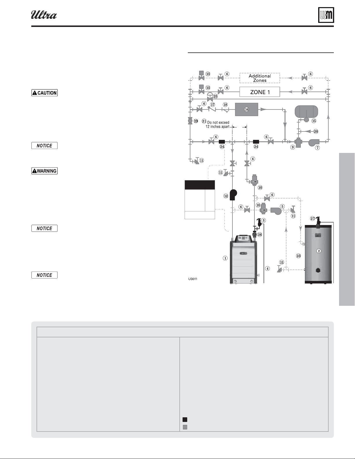
Part number 550-100-400/0119
55
Legend — Figure 51
1 Ultra boiler
2 Indirect water heater (DHW), if used
3 Boiler relief valve (see page 9 for piping details)
4 Relief valve discharge piping (see page 9 for details)
5 DHW circulator (see page 56 for suggested sizing)
6 Isolation valves
7 System circulator (see information above for wiring)
8 Diaphragm (or bladder) type expansion tank (see page 56 for piping of
closed-type expansion tank, if used)
9 Air separator [with automatic air vent only on systems using diaphragm
(or bladder) type expansion tank]
10 Flow/check valves
11 Purge/drain valves
12 Boiler circulator
13 Zone valves, typical
15 Closed-type expansion tank
16 Water chiller
17 Check valve
18 Strainer
19 Balancing valve
20 Make-up water supply
21 Primary/secondary connection (tees no more than 12 inches apart)
23 DHW supply/return
24 Strap system supply and return sensors to lines as shown, at least 6 pipe
diameters (but no more than 3 feet) from boiler connection tees.
25 Systems using high-head pumps may require a bypass pressure regulator
to prevent damage to control valves.
26 Temperature/Pressure gauge
27 DHW relief valve, if used
Items supplied with boiler
Items supplied by others
Chilled water systems
1. Install boiler so that chilled medium is piped in parallel with
the heating boiler. Use appropriate valves to prevent chilled
medium from entering boiler. See Figure 51 for typical instal-
lation of balancing valve and check valve.
Use the pipe size shown in Fig-
ure 51 on all boiler loop piping (connecting boiler
to and from the primary/secondary connection,
item 21).
Failure to follow these guidelines could
result in system problems.
2. The space heating system may be zoned with circulators if
a separate circulator is supplied for the chilled water loop.
If antifreeze is used in the system, consider the ef-
fects of antifreeze on circulator sizing and DHW
performance. Some local codes may require double-
wall DHW heat exchanger design.
Chilled medium, if used, is piped in parallel with
heating boiler as shown in Figure 51 . Use appropri-
ate valves to prevent chilled medium from entering
boiler.
If boiler is connected to heating coils located in
air handling units where they can be exposed to
refrigerated air, use fl ow control valves or other
automatic means to prevent gravity circulation
during cooling cycle.
By default, the U-Control Module turns off space
heating during DHW heating (if DHW input is
priority 1). The boiler circulator will turn off, pre-
venting hot water from circulating to the system
(optional timeout setting can be used to override).
The fl ow/check valve shown on the boiler outlet
piping prevents gravity circulation in the boiler
loop during DHW heating.
Overriding the Outdoor Reset function by setting control
to DHW mode when system is intended for space heat-
ing may violate Section 303 of the 2007 Energy Act. See
page 137 for compliance information and exemptions.
3. Controlling the circulators
a. The U-Control can control up to three circulators (boiler
circulator and two others). Refer to Field wiring, begin-
ning on page 30 , for instructions on wiring to circulators.
Figure 51Chilled ater sstem plus optional
pipin
Install water piping — advanced (continued)
b. The factory default settings are: DHW circulator as
Circulator 1, boiler circulator as Circulator 2. See Field
wiring instructions, beginning on page 30 , for details.
®
Series 4
gas-fired water boiler — Boiler Manual
Boiler loop pipe size
Ultra-80, 105
Ultra-155, 230
Ultra-299/310,
399
1”
1¼”
1½”
See CAUTION at left.
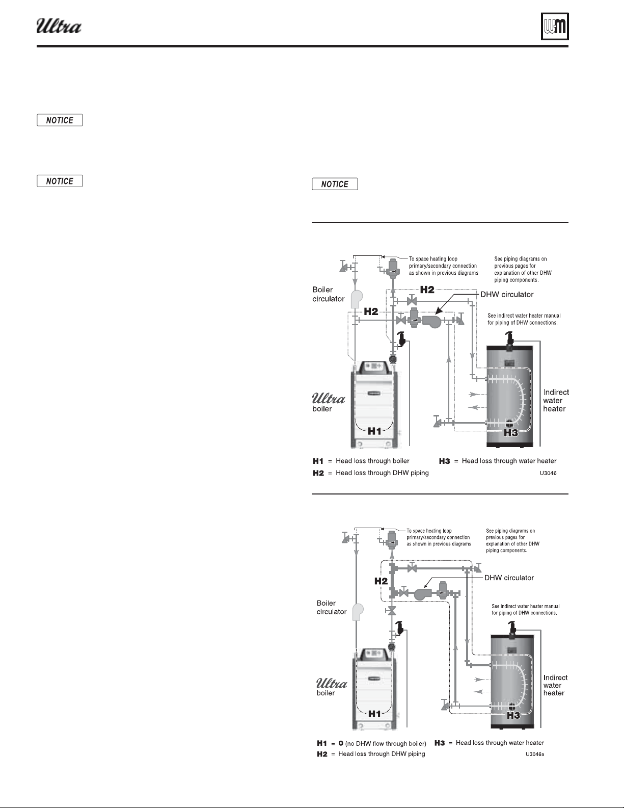
Part number 550-100-400/0119
56
Sizing dire ct-connected DHW piping
The closest circulator selection (from Figure 55, page 57 )
that can deliver 12 gpm at 22.7 feet head is either a Taco
1400 (top chart) or a Taco 0013 (bottom chart).
Note that, if the water heater were piped as in Figure 53 ,
then H1 would be 0, so total head loss would be H2 + H3,
or 9.4 feet (3.9 + 5.5). A Taco 0010 would handle the load
if piped this way.
See previous pages in this manual for piping details
not shown below. For DHW piping as shown below,
use sizing information in Figure 54, page 57 .
Figure 52 pipin direct-connected across the oiler
Figure 53 pipin as a secondar circuit for hih-
o-rate applications
®
Series 4
gas-fired water boiler — Boiler Manual
Direct-connected DHW piping
For ,
refer to the AQUA PLUS water heater manual for
application information. Also see quick-select in-
formation on page 14 . The information here is for
other water heater designs.
When using the Ultra boiler for dedicated DHW
applications, use the circulator supplied with
the boiler (007 for Ultra-80/105; 0014 for Ul-
tra-155/230/299/310; 0013 for Ultra-399) to circu-
late to the water heater, except where higher fl ow
rates may be required for the heater used. Use the
following method to select a circulator for the water
heater on combined space heating/DHW systems.
1. To pipe the DHW tank and boiler, follow the suggested piping
diagrams beginning on page 12 .
2. Figure 55, page 57 shows the pump curves for typical DHW
circulators. Use these curves along with boiler pressure drop
data from Figure 54, page 57 to size the DHW piping and
circulator.
3. Procedure to select a DHW circulator:
:
From the water heater manufacturer’s data, fi nd:
feet water column (this is H3 in the formula below).
:
Find your boiler model in
Figure 54, page 57 .
Select a fl ow rate in the Flow rate column just larger than the
required boiler water fl ow rate from Step 1.
:
Read across the row selected to fi nd the boiler pressure drop,
H1, and the pressure drop in the piping, H2. Make sure to
use the copper pipe size given in column 3 when piping the
water heater.
:
Add the pressure drop across the water heater, from Step 1,
to the values of H1 and H2 for total head loss.
:
Select a circulator that can deliver the required fl ow rate,
gpm, against the total head loss found in Step 4.
:
Consider an Ultra-155 used with a water heater that requires
a fl ow of 12 gpm with boiler water at 190°F. The water heater
is to be piped as in Figure 52 .
From the example water heater manufacturer’s data, the
head loss across the water heater at 12 gpm is 5.5 feet water
column.
Read down the fi rst column of
Figure 54, page 57 for the
Ultra-155 until you fi nd a fl ow rate just larger than the re-
quired 12 gpm. You’ll fi nd a value of 13 gpm in the third row.
At 13 gpm, with an Ultra-155, the recommended pipe size
is 1¼ inch. From the table, the head losses are:
H1 = 13.3 feet H2 = 3.9 feet
H3 = 5.5 feet (from water heater manufacturer’s data)
H
total
= 13.3 + 3.9 + 5.5 = 22.7 feet.
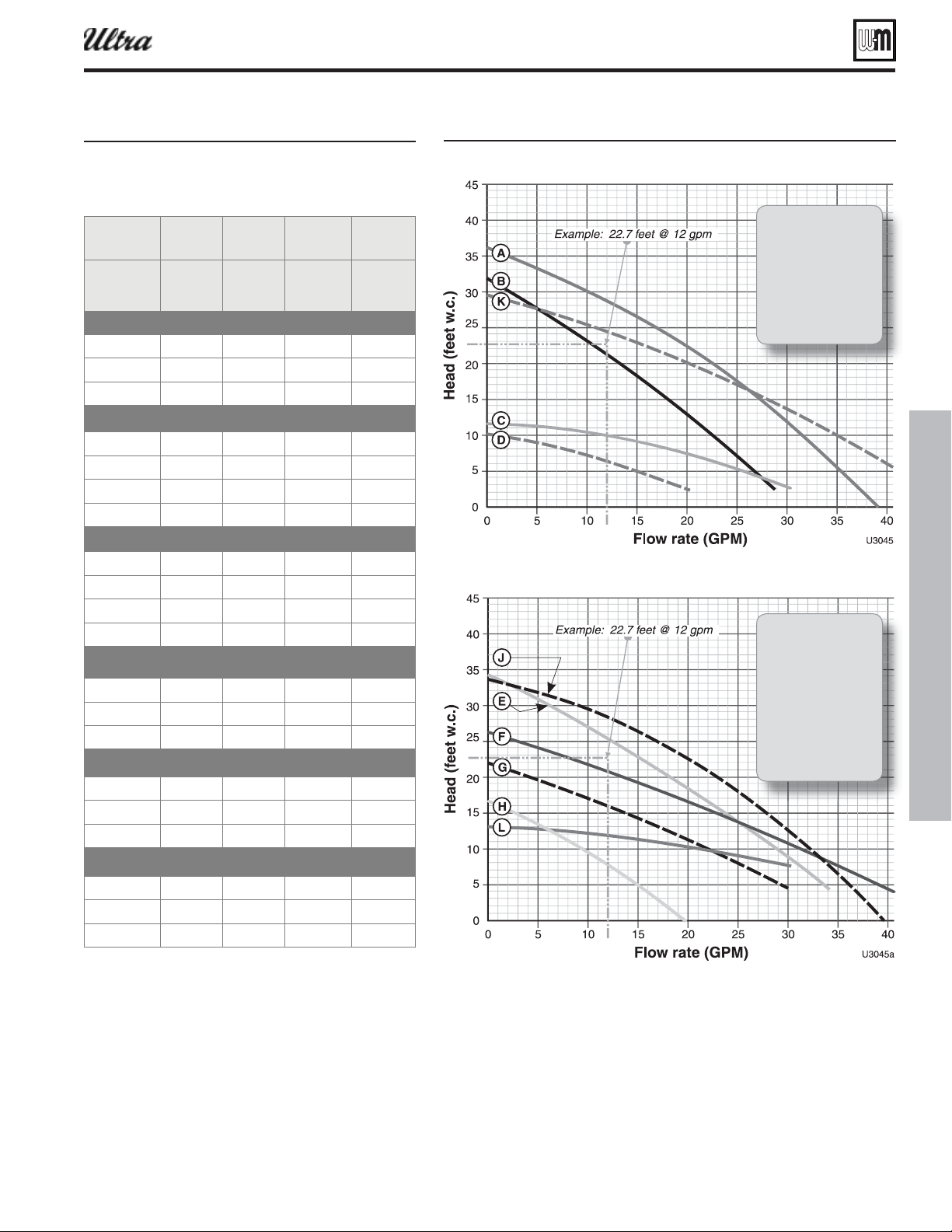
Part number 550-100-400/0119
57
Figure 55 ump cures for tpical circulators suested for loop
Figure 54ipe siin and head losses for
applications
(H1=Ultra boiler head loss;
H2=piping head loss)
Flow
rate
Temp
rise
Pipe
size
H1 H2
GPM °F Inches
Boiler head
loss
Feet w.c.
Piping head
loss
Feet w.c.
72016.62.7
9 16 1 11.6 4.2
10 14 1¼ 14.6 2.5
72717.02.7
9 21 1 11.2 4.2
10 19 1¼ 13.6 2.5
13 14 1¼ 22.2 3.9
9311¼6.22.1
10.0 28 1¼ 7.7 2.5
13 21 1¼ 13.3 3.9
16 17 1¼ 20.5 5.7
13 32 1¼ 9.4 3.9
16 26 1¼ 13.7 5.7
21 20 1½ 22.0 2.9
18 31 1½ 6.6 2.2
22 25 1½ 9.5 3.1
29 19 2 17.4 2.9
22 34 1½ 9.5 3.1
29 25 2 15.5 2.9
36 20 2 22.8 4.3
Taco 0011
Taco 0010
Taco 007
Taco 1400-30
Taco 0013
Grundfos 43-75
Taco 0014
Grundfos 15-42
Taco 1400-20
Taco 0012
®
Series 4
gas-fired water boiler — Boiler Manual
Sizing dire ct-connected DHW piping (continued)
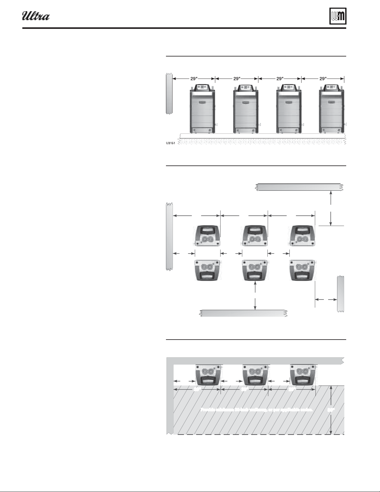
Part number 550-100-400/0119
58
Multiple boiler installations
Placing multiple boilers
1. Locate multiple boilers in boiler room according to:
a. Figure 56 (side-to-side), or
b. Figure 57 (back-to-back).
c. Figure 58 (wall mounting).
2. Provide indicated clearances around boilers for
access and servicing. If recommended dimensions
are not possible, provide at least the minimum
clearances given on page 5 . Also follow local codes.
3. Construct boiler foundation if boiler room fl oor
is uneven or if there is a danger of fl ooding. Size
foundation to allow for clearance and spacing di-
mensions shown in the illustrations at right.
4. Chalk line boiler locations on foundation or boiler
room fl oor.
5. Uncrate, assemble and mount boilers according to
instructions in this manual.
6. Provide clearance for installation of venting, air
piping, gas piping, expansion tank, primary circula-
tor and other accessories.
Wall mounting
(Ultra Models 80 – 399)
1. Ultra boilers may be wall mounted, following the
instructions on page 50 . (See Repair parts section
for part number of wall mounting kit.)
2. When wall mounting boilers, provide approxi-
mately 6 inches between boilers for easy removal
of boiler jacket door. See Figure 58 .
3. Follow all applicable codes regarding piping, electri-
cal connections and clearances.
4. When wall mounting boilers, verify the wall con-
struction is suitable for the structural load. See
page 50 for details.
Figure 56 Side-to-side mountin of multiple Ultra oilers
Figure 57 Bac-to-ac installation of multiple Ultra oilers
1ΣxÓ
Figure 58 all mountin multiple Ultra oilers
1ΣxÎ
*ÀÛ`iÊÕÊÎäVÊÜ>Ü>Þ]ÊÀÊ«iÀÊ>««V>LiÊV`ið
®
Series 4
gas-fired water boiler — Boiler Manual
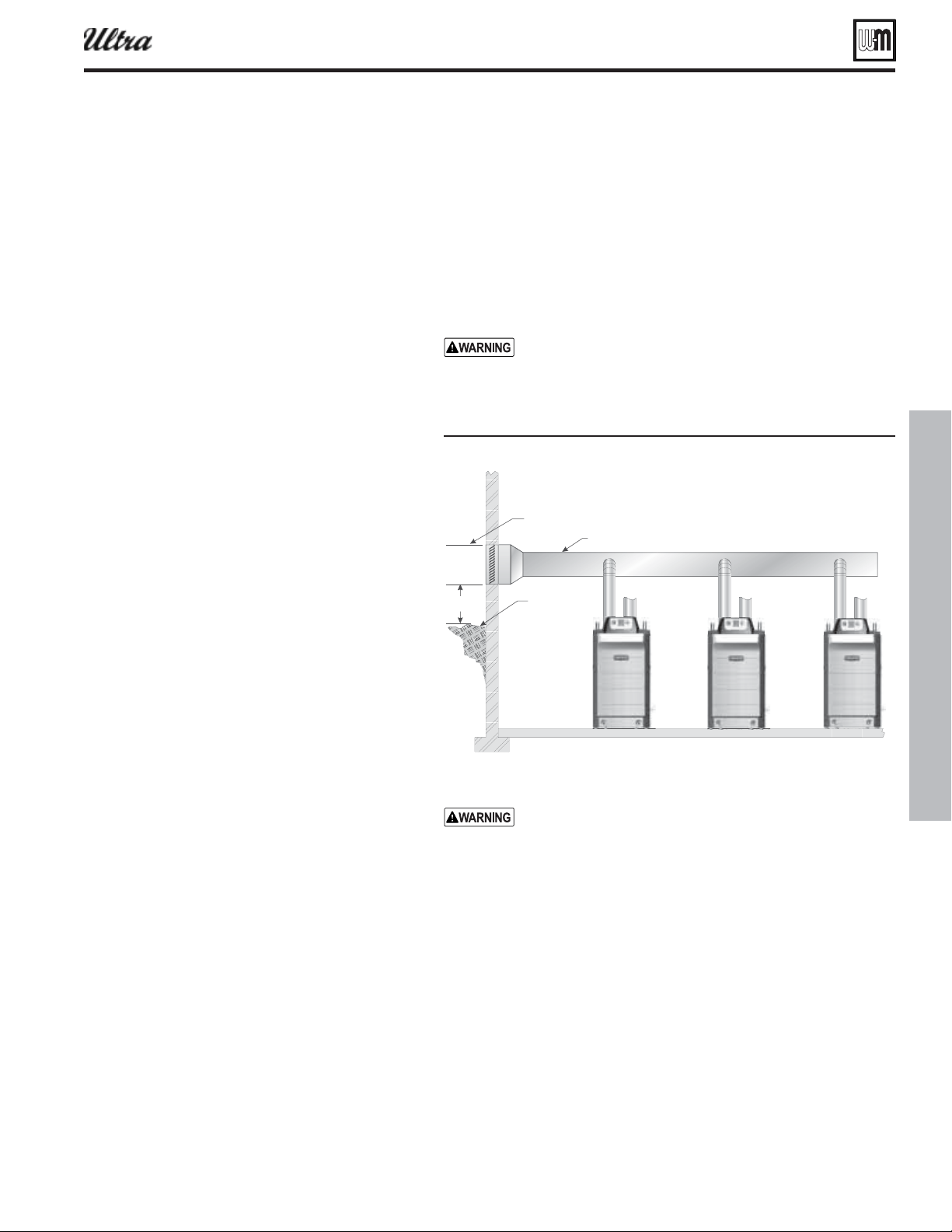
Part number 550-100-400/0119
59
Figure 59 anifolded comustion air option
1ΣÈä
À6iÌ
£Ó¸Ê
À>`iÊÀ
ÃÜÊi
ÕÊÎÊviiÌÊLiÜÊ>ÞÊÛiÌÊÌiÀ>ÌÊÜÌÊ£äÊviiÌ
À6iÌÀ6iÌ
ÀÊ`ÕVÌ
Multiple boiler installations (continued)
®
Series 4
gas-fired water boiler — Boiler Manual
Manifolded combustion air option
1. Multiple Ultra boilers can use a common combustion air manifold.
a. See Figure 139, page 138 for minimum cross sectional area of
combined air ducts.
b. Provide minimum clearance to adjacent vents and grade/snow line
as shown in Figure 59 .
c. Provide minimum free area in duct (adjusted for louver restriction)
of
total boiler input.
d. If combustion air damper is used, wire to boilers to prevent opera-
tion except after damper has opened.
ONLY air piping can be combined. DO NOT use combined
vent piping. Flue gas leakage and boiler component damage
can occur. Failure to comply could result in severe personal
injury, death or substantial property damage.
DO NOT use common venting — the manifold option is
only for combustion air — all vent pipes must be routed and
terminated individually as described in this manual.
See Figure 139, page 138 for minimum cross sectional area
of combined air ducts.
OR
Calculate required cross section (for area in square inches):
Example: A multiple boiler system with (6) Ultra-155 boilers
has a total input of 6 x 155 = MBH (930,000 Btuh). The
required duct cross sectional area is:
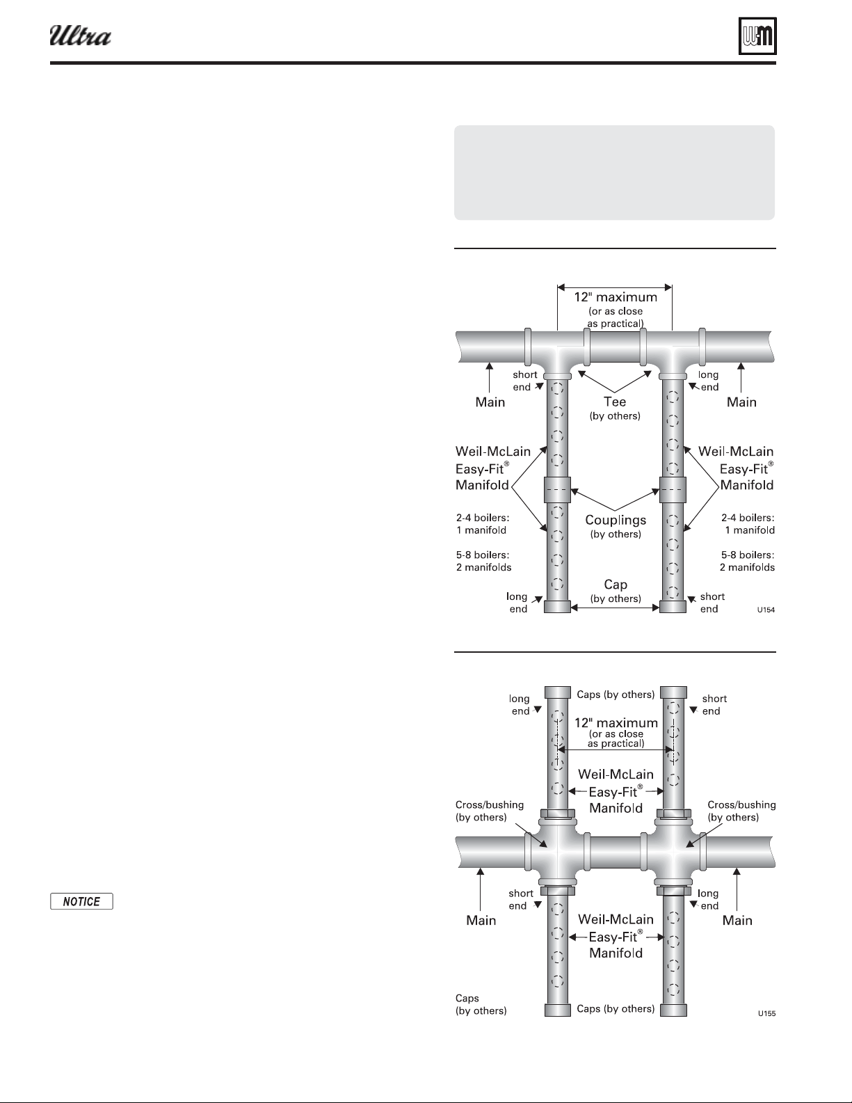
Part number 550-100-400/0119
60
Multiple boiler installations (continued)
Easy-Fit
piping installation
1. Main header and Easy-Fit
®
Manifold pipe sizing.
a. New system — See page 10 .
b. Replacing boilers in an existing system — Without reducing
size, connect system supply and return lines. Install tees or
crosses for Easy-Fit
®
manifolds as shown in Figure 60 or Fig-
ure 61 . Size manifolds to handle total connected boiler output
as shown.
2. Provide connections in main header for Easy-Fit® manifolds as
close as possible to the midpoint of multiple boilers.
a. Use tees for four or less boilers, as in Figure 60 .
b. Use either tees ( Figure 60 ) or crosses ( Figure 61 ) for fi ve or
more boilers.
3. Manifold placement:
a. To alternate spacing for supply and return lines to boilers,
reverse the short-end and long-end of the manifolds as shown
in Figure 60 and Figure 61 .
b. Return manifold must be on the return side of the main and
supply manifold must be on the supply side of the main. Draw-
ings in this manual show fl ow in system main from right to
left. For system fl owing left to right, reverse the locations of
the manifolds accordingly.
4. Connect from Easy-Fit® manifold branches to boiler supply and
return connections using copper or steel pipe, sized for the required
fl ow rate.
5. Provide a fl ow/check valve in the supply piping of each boiler as
shown in piping diagrams in this manual. Install an isolation valve
on the supply and return of each boiler as shown. Some local codes
may require the use of individual water level controls and limits
on each boiler when isolation valves are installed.
6. Install main system air eliminator and primary circulator in sup-
ply piping as shown in piping diagrams. Place expansion tank on
suction side of system circulator as shown.
7. Install system accessories as shown in drawings.
8. Piping recommendation drawings:
a. Figure 60 and Figure 61 show details of Easy-Fit
®
manifolds.
b. Figure 62, page 61 is a schematic piping drawing showing the
locations of typical boiler piping and system piping, including
limits and other devices often required by local codes.
c. Figure 63, page 62 and Figure 64, page 63 are three-dimensional
piping drawings of typical multiple boiler installation.
d. Figure 65, page 64 shows recommended piping when an isolat-
ing heat exchanger is needed.
9. If desired, other primary/secondary piping arrangements can be
used.
When using isolation valves on each boiler, some codes
may require providing a low water control and additional
limit for each boiler. Consult local codes to determine
if omission of the individual boiler isolation valves
may allow the use of a single water level control and
additional limit for the entire multiple boiler system.
. This will satisfy some code requirements for
low water cutoff protection.
Figure 60 Sinle-sided -it eader connection
Figure 61 oule-sided -it eader connection
®
Series 4
gas-fired water boiler — Boiler Manual
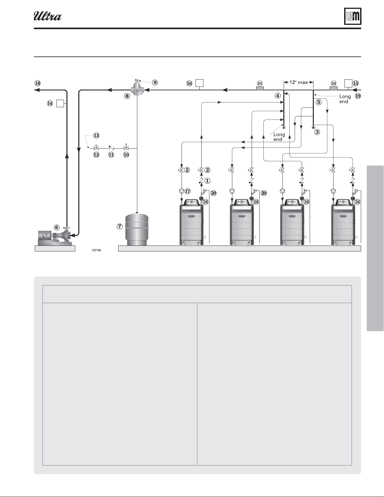
Part number 550-100-400/0119
61
Multiple boiler installations (continued)
Legend — Figure 62
1 Flow/check valve (each boiler)
2 Isolation valves (when used)
3 Cap
4 Easy-Fit® Manifold (supply) — layout and size per page 60
5 Easy-Fit® Manifold (return) — layout and size per page 60
6 Primary circulator
7 Expansion tank (diaphragm type)
8 System air eliminator
9 System automatic air vent
10 Pressure reducing valve
11 Check valve or backfl ow preventer, as required by applicable codes
12 Isolation valve
13 Cold water supply
14 Supply water temperature control (when used)
15 Low water cutoff (when used) (place above primary header)
16 Water fl ow switch (when used)
17 Boiler circulator (each boiler)
18 System supply
19 System return
20 Boiler relief valve and discharge piping, installed per Ultra Boiler
Manual
24 Strap system supply and return sensors to lines as shown, at least 6
pipe diameters (but no more than 3 feet) from boiler connection tees.
26 Temperature/pressure gauge
Figure 62 ipin schematic tpical pipin for multiple Ultra oilers usin eil-cLain as-it manifolds
®
Series 4
gas-fired water boiler — Boiler Manual
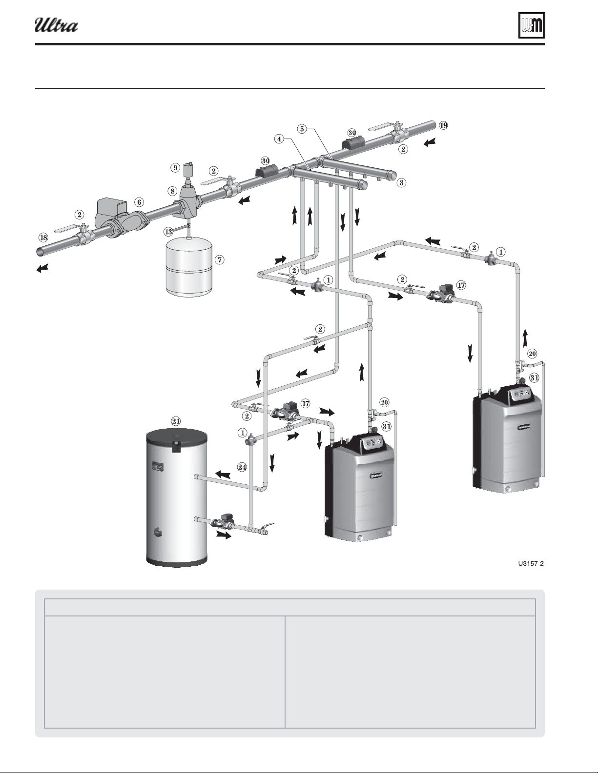
Part number 550-100-400/0119
62
Multiple boiler installations (continued)
Legend — Figure 63
1 Flow/check valve (each boiler)
2 Isolation valves (when used)
3 Caps
4 Easy-Fit® Manifold (supply) — layout and size per page 60
5 Easy-Fit® Manifold (return) — layout and size per page 60
6 Primary circulator
7 Expansion tank (diaphragm type)
8 System air eliminator
9 System automatic air vent
13 Cold water supply
17 Boiler circulator (each boiler)
18 System supply
19 System return
20 Boiler relief valve and discharge piping, installed per Ultra Boiler Manual
21 Indirect-fi red storage water heaters (Weil-McLain AQUA PLUS shown) —
Example is shown connected to one boiler of the system. Preferably, use
the last boiler in the lead/lag sequence and set its Priority to
so it will switch to DHW fi ring and turn off its boiler circulator on a call
for domestic water heating.
24 DHW boiler-side circulator
30 Strap system supply and return sensors to lines as shown, at least 6 pipe
diameters (but no more than 3 feet) from boiler connection tees.
32 Temperature/pressure gauge
Figure 63 ipin laout tpical pipin for multiple Ultra oilers usin eil-cLain as-it manifolds -oiler sstem
®
Series 4
gas-fired water boiler — Boiler Manual
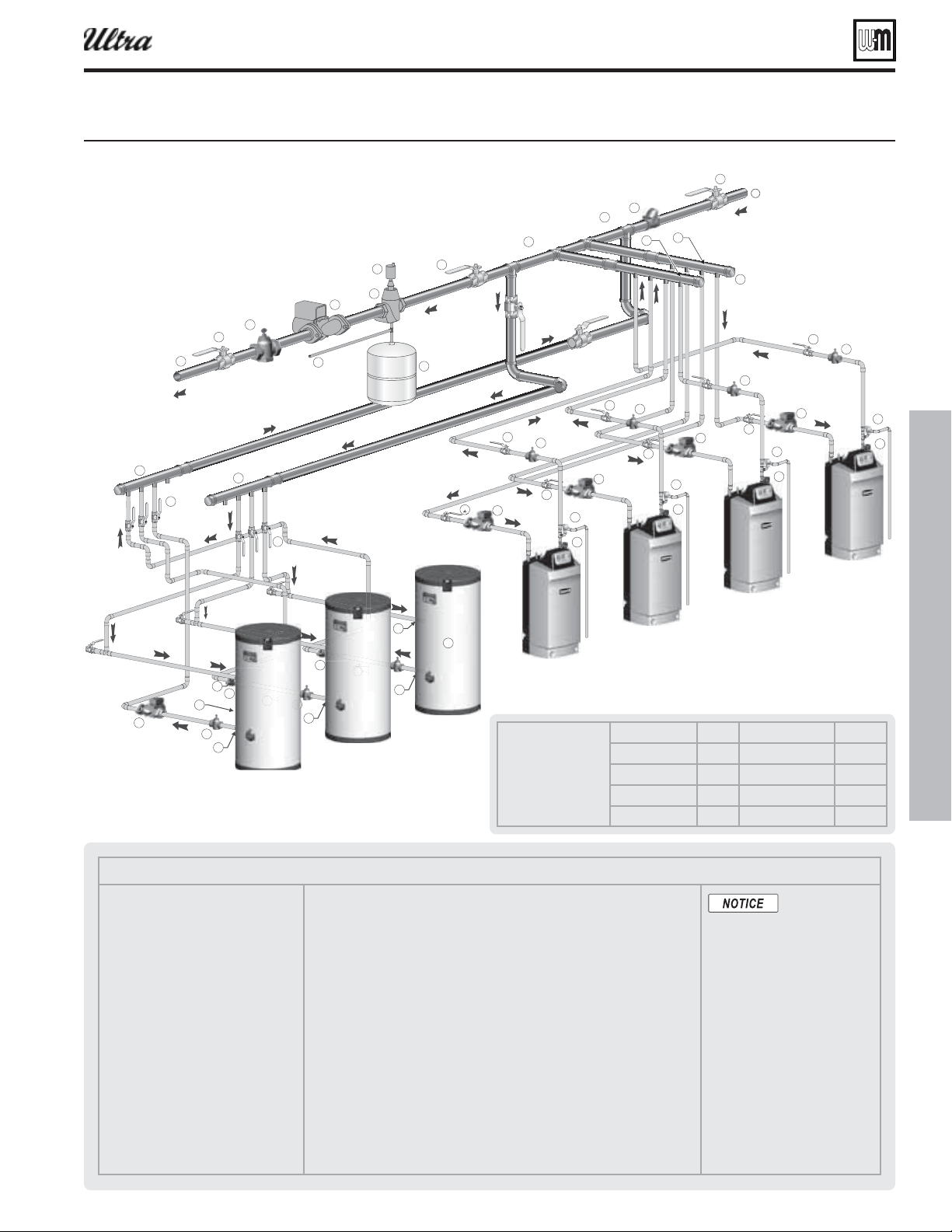
Part number 550-100-400/0119
63
Figure 64 ipin laout tpical pipin for multiple Ultra oilers ith storae heaters -oiler sstem
Suggested DHW
boiler-side pipe
sizing
(for max 0.04
feet head loss per foot of
total equivalent length,
TEL)
Flow rate Size Flow rate Size
1 – 3.9 gpm ¾” 24 – 45 gpm 2”
3.9 – 7.1 gpm 1” 45 – 75 gpm 2½”
7.1 – 16 gpm 1¼” 75 - 140 gpm 3”
16 – 24 gpm 1½” 140 – 290 gpm 4”
Multiple boiler installations (continued)
®
Series 4
gas-fired water boiler — Boiler Manual
Legend — Figure 64
1 Flow/check valve (each boiler)
2 Isolation valves (when used)
3 Caps
4 Easy-Fit® Manifold (supply) — layout
and size per page 60
5 Easy-Fit® Manifold (return) — layout
and size per page 60
6 Primary circulator
7 Expansion tank (diaphragm type)
8 System air eliminator
9 System automatic air vent
13 Cold water supply
17 Boiler circulator (each boiler)
18 System supply
19 System return
20 Boiler relief valve and discharge piping,
installed per Ultra Boiler Manual
21 Indirect-fi red storage water heaters (Weil-McLain AQUA PLUS shown) — Example
is shown with reverse-return boiler-side piping using a single circulator. Alternate:
each water heater could have its own circulator.
22 Boiler water inlet
23 Boiler water outlet
24 DHW boiler-side circulators
25 DHW boiler-side supply Easy-Fit® Manifold
26 DHW boiler-side return Easy-Fit® Manifold
27 Flow/check valves (to prevent induced or gravity fl ow in heating system or DHW
piping)
28 Check valve to prevent heat migration in heating system.
29 See water heater manual for DHW piping — The DHW piping must also be mani-
folded together since the boiler-side piping is manifolded. If DHW heaters supply
separate DHW circuits, provide an individual circulator for each water heater, and
control each circulator by its water heater’s aquastat.
30
Strap system supply and return sensors to lines as shown, at least 6 pipe
diameters (but no more than 3 feet) from boiler connection tees.
31 Temperature/pressure gauge
This piping is sug-
gested only. The
layout above should be controlled
with a boiler sequencing panel that
provides DHW operation as well.
Wire the heating system circulator
to operate only on call for heat. Al-
ternatively, use the boiler sequencing
panel to provide domestic priority
by disabling the heating system cir-
culator any time there is a DHW call
for heat. The boiler circulators, item
17, must operate on any call for heat,
whether heating system or DHW.
Offset the DHW boiler-side supply
and return manifolds as shown so
the total run of pipe and fi ttings to
each of the water heaters is approxi-
mately equal.
6TQ
À>
Û>ÛiÃ
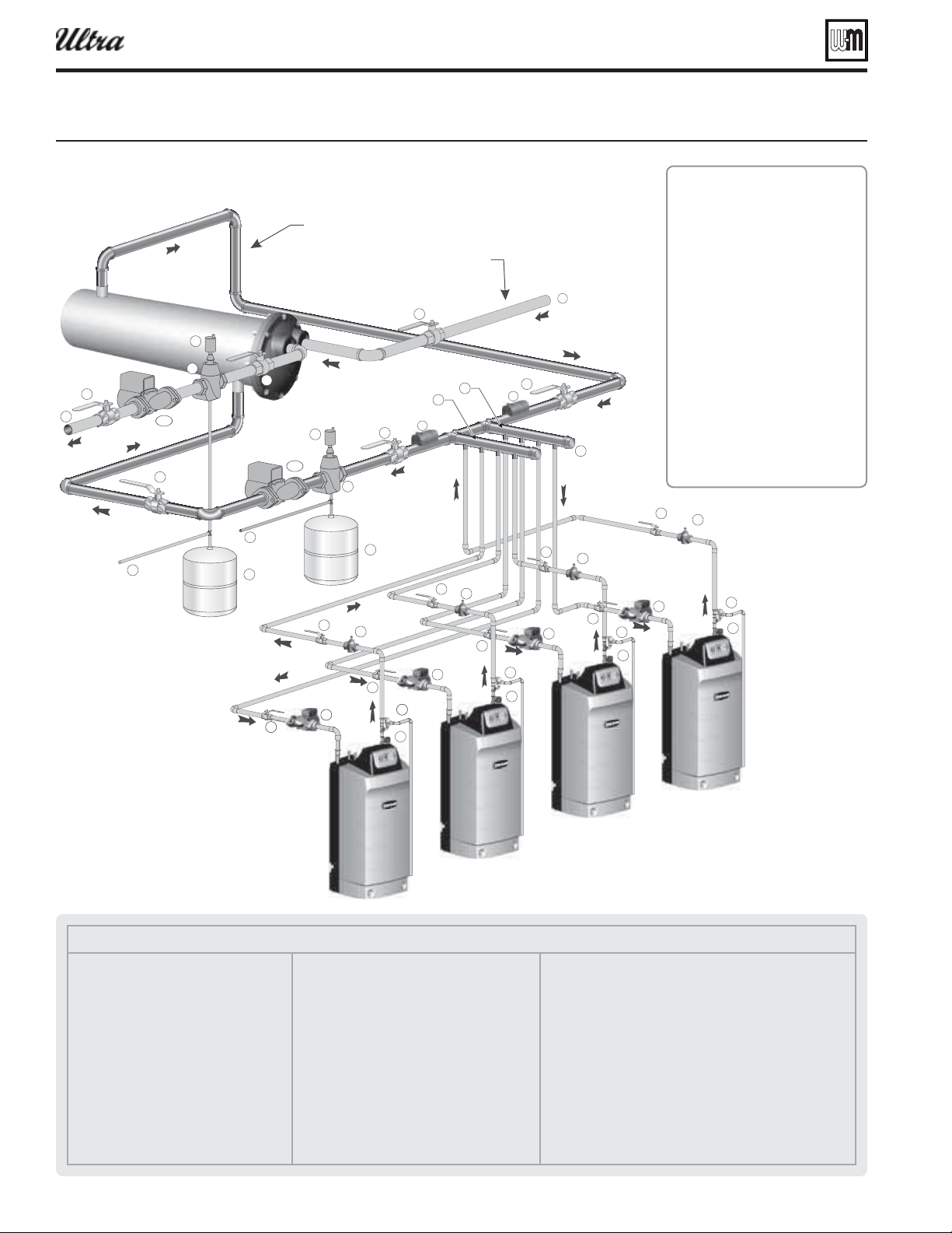
Part number 550-100-400/0119
64
Multiple boiler installations (continued)
Figure 65 ipin laout tpical pipin for multiple Ultra oilers usin isolation echaner
1. Large volume systems with high
mineral content in water.
2. Systems exposed to untreated
quantities of makeup water.
3. Old systems severely contami-
nated with scale and rust buildup
inside piping and heat distribu-
tion units.
4. Process applications.
5. Commercial service water ap-
plications.
6. High water pressure applications,
requiring pressure relief setting
in heating system more than 30
PSIG (tall buildings). See notes
below.
®
Series 4
gas-fired water boiler — Boiler Manual
Legend — Figure 65
1 Flow/check valve (each boiler)
2 Isolation valves (when used)
3 Cap
4 Easy-Fit® Manifold (supply) — layout
and size per page 60
5 Easy-Fit® Manifold (return) — layout
and size per page 60
6a Heating system circulator (exchanger
tube-side)
6b Heat exchanger shell-side circulator
7 Expansion tanks (diaphragm type)
8 System air eliminator
9 System automatic air vent
13 Cold water supply connections
17 Boiler circulator (each boiler)
18 Heating system supply
19 Heating system return
20 Boiler relief valve and discharge piping,
installed per Ultra Boiler Manual
30 Strap system supply and return sensors to
lines as shown, at least 6 pipe diameters (but
no more than 3 feet) from boiler connection
tees.
31 Temperature/pressure gauge
Notes:
1. Contact heat exchanger manufacturer for heat exchanger
shell-side and tube-side piping and circulator require-
ments. Tube-side flow and temperatures must meet
heating system requirements.
2. Contact heat exchanger manufacturer for sizing heat
exchanger.
3. Heat exchanger shell-side circuit requires its own expan-
sion tank as shown.
4. Heating system circuit requires its own expansion tank,
as shown, plus its own relief valve set to protect heating
system and heat exchanger piping and components.
5. When individual isolation valves are used, individual
boiler and level controls may be required.
6
E
D
i>ÌÊiÝV>}iÀ
iÀÃ`iÊVÀVÕÌ
i>Ì}ÊÃÞÃÌiÊVÀVÕÌ

Part number 550-100-400/0119
65
Venting/air piping — Massachusetts installations
®
Series 4
gas-fired water boiler — Boiler Manual
(a) For all sidewall horizontally-vented gas-fueled equipment
installed in every dwelling, building or structure used in
whole or in part for residential purposes, including those
owned or operated by the Commonwealth and where the
side wall exhaust vent termination is less than seven (7) feet
above fi nished grade in the area of the venting, including but
not limited to decks and porches, the following requirements
shall be satisfi ed:
1.
. At the time of installation of the side wall horizon-
tal vented gas fueled equipment, the installing plumber or
gas fi tter shall observe that a hard wired carbon monoxide
detector with an alarm and battery back-up is installed on
the fl oor level where the gas equipment is to be installed.
In addition, the installing plumber or gas fi tter shall
observe that a battery operated or hard wired carbon
monoxide detector with an alarm is installed on each ad-
ditional level of the dwelling, building or structure served
by the side wall horizontal vented gas fueled equipment.
It shall be the responsibility of the property owner to
secure the services of qualifi ed licensed professionals for
the installation of hard wired carbon monoxide detectors
a. In the event that the side wall horizontally vented gas
fueled equipment is installed in a crawl space or an
attic, the hard wired carbon monoxide detector with
alarm and battery back-up may be installed on the
next adjacent fl oor level.
b. In the event that the requirements of this subdivision
can not be met at the time of completion of installa-
tion, the owner shall have a period of thirty (30) days
to comply with the above requirements; provided,
however, that during said thirty (30) day period, a
battery operated carbon monoxide detector with an
alarm shall be installed.
2.
. Each
carbon monoxide detector as required in accordance with
the above provisions shall comply with NFPA 720 and be
ANSI/UL 2034 listed and IAS certifi ed.
3.
. A metal or plastic identifi cation plate shall
be permanently mounted to the exterior of the build-
ing at a minimum height of eight (8) feet above grade
directly in line with the exhaust vent terminal for the
horizontally vented gas fueled heating appliance or
equipment. The sign shall read, in print size no less than
one-half (1/2) inch in size, “GAS VENT DIRECTLY BE-
LOW. KEEP CLEAR OF ALL OBSTRUCTIONS.”
4.
. The state or local gas inspector of the
side wall horizontally vented gas fueled equipment shall
not approve the installation unless, upon inspection,
the inspector observes carbon monoxide detectors and
signage installed in accordance with the provisions of
248 CMR 5.08(2)(a) 1 through 4.
(b)
: The following equipment is exempt from
248 CMR 5.08(2)(a)1 through 4:
1. The equipment listed in Chapter 10 entitled “Equipment
Not Required To Be Vented” in the most current edition
of NFPA 54 as adopted by the Board; and
2. Product Approved side wall horizontally vented gas fueled
equipment installed in a room or structure separate from
the dwelling, building or structure used in whole or in
part for residential purposes.
(c)
. When the manufacturer of
Product Approved side wall horizontally vented gas equip-
ment provides a venting system design or venting system
components with the equipment, the instructions provided
by the manufacturer for installation of the equipment and
the venting system shall include:
1. Detailed instructions for the installation of the venting
system design or the venting system components; and
2. A complete parts list for the venting system design or
venting system.
(d)
. When the manufac-
turer of a Product Approved side wall horizontally vented gas
fueled equipment does not provide the parts for venting the
fl ue gases, but identifi es “special venting systems”, the follow-
ing requirements shall be satisfi ed by the manufacturer:
1. The referenced “special venting system” instructions shall
be included with the appliance or equipment installation
instructions; and
2. The “special venting systems” shall be Product Approved
by the Board, and the instructions for that system shall
include a parts list and detailed installation instructions.
(e) A copy of all installation instructions for all Product Approved
side wall horizontally vented gas fueled equipment, all venting
instructions, all parts lists for venting instructions, and/or all
venting design instructions shall remain with the appliance
or equipment at the completion of the installation.
Instructions for the
Commonwealth of Massachusetts
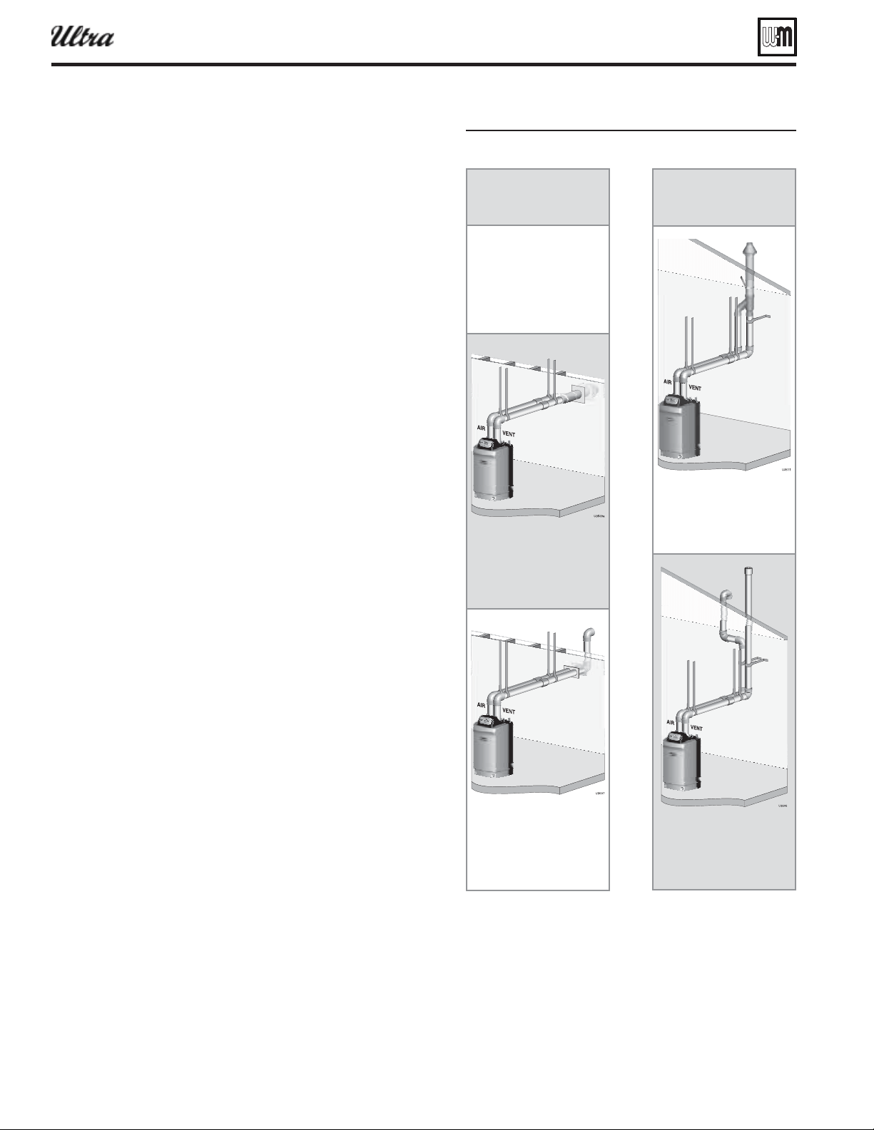
Part number 550-100-400/0119
66
Vent /air piping — options
Vent and air pipe termination options
1. Vent and air piping must terminate out the sidewall or through
the roof of the building, using only one of the methods described
in this manual.
2. Sidewall options (see Figure 12, page 18 , left side):
a. TOP: Weil-McLain termination cap (kit included with
boiler) — see page 67 for instructions.
b. MIDDLE: Concentric PVC pipe (requires special kit,
page 129 ).
c. BOTTOM: Separate air pipe and vent pipe.
3. Vertical options ( Figure 12, page 18 , right side):
a. TOP: Concentric PVC pipe (requires special kit, page 129 ).
b. BOTTOM: Separate air pipe and vent pipe.
Vent and air pipe diameters
1. Vent and air pipe diameters can be as specifi ed in Figure 12, page 18 .
Vent and air pipe minimum length
1. Vent pipe and air pipe must each be , with
2 elbows if sidewall venting or 1 elbow if vertical venting.
Vent and air pipe installation sequence
Step 1 Install the boiler.
Step 2 Determine the termination method — sidewall or vertical,
concentric or separate pipes, etc.
Step 3 Determine proper location for wall or roof penetration for
each termination.
Step 4 Install termination assembly as described in this manual.
Step 5 Install air and vent piping from boiler to termination.
Step 6 Install pipe supports and brackets as required.
Figure 66
Sidewall
termination
Vertical
termination
®
Series 4
gas-fired water boiler — Boiler Manual
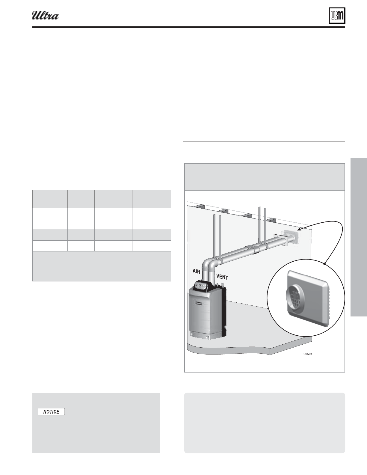
Part number 550-100-400/0119
67
®
Series 4
gas-fired water boiler — Boiler Manual
Figure 67 ent and air pipe reuirements
Vent and air pipe installation sequence
Step 7 Install the boiler.
Step 8 Determine the termination method — sidewall or vertical,
concentric or separate pipes, etc.
Step 9 Determine proper location for wall or roof penetration
for each termination.
Step 10 Install termination assembly as described in this manual.
Step 11 Install air and vent piping from boiler to termination.
Step 12 Install pipe supports and brackets as required.
— see information beginning on
page 66 . Options include other
termination fittings and vertical
terminations.
Commonwealth of Massachusetts
When the boiler is installed within the Commonwealth of Mas-
sachusetts:
This product must be installed by a licensed plumber or
gas fi tter.
Sidewall vent air installations — see instructions on page 65 .
Sidewall termination
Use appropriate adapters here needed Ultra- throuh
- reuire . inch outside diameter pipe at the oiler ent
and air connections. Ultra- - and - oilers
reuire . inch outside diameter pipe at the oiler ent and
air connections.
Vent and air pipe minimum length
1. Vent pipe and air pipe must each be at least 2 feet long,
with two (2) elbows if sidewall venting or 1 elbow if
vertical venting.
Vent and air pipe maximum length
1. See Figure 69, page 68 for maximum length of vent and
air piping using the Weil-McLain sidewall vent cap.
Vent and air pipe termination options
1. This section covers sidewall termination using the
Weil-McLain sidewall vent cap.
a. Models 80, 105 and 155 requires a 3-inch pipe size kit.
b. Models 230, 299/310 and 399 requires a 4-inch pipe
size kit.
c. The Weil-McLain sidewall vent/air cap kit includes the
termination cap, inside and outside wall plates, and
mounting hardware to secure the plates.
2. For other termination options and parts required,
see page 66 .
Vent and air pipe requirements
1. Vent and air pipe diameters can be as specified in
Figure 67 .
Figure 68 ent and air termination options
Sidewall vent/air termination: Weil-McLain cap
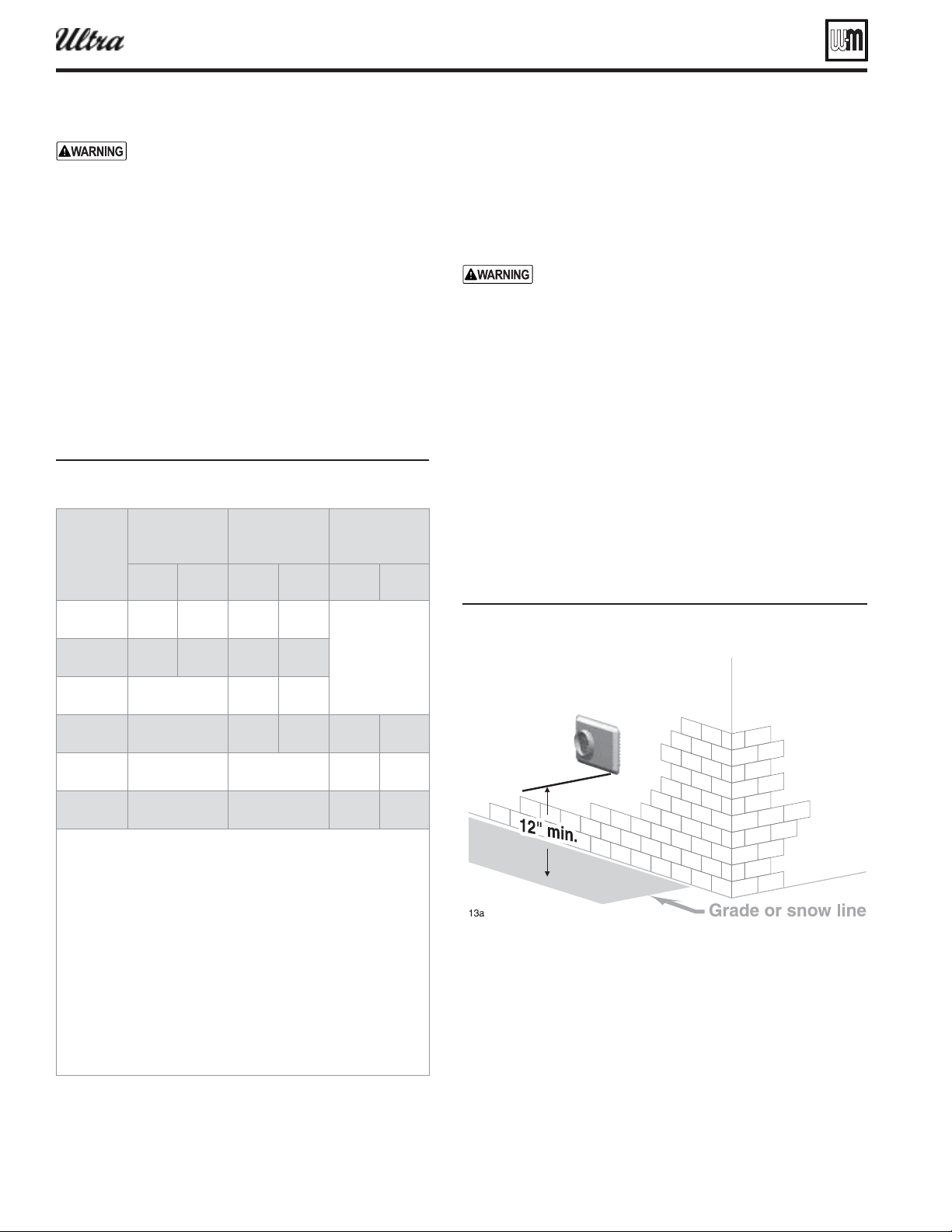
Part number 550-100-400/0119
68
Provide pipe adapters as needed where pipe size
is different from termination connections or
boiler connections, and for all AL29-4C vent pipe
connections at the boiler and the termination.
Allowable vent/air pipe materials
1. Use only the materials listed in Figure 13, page 19 .
Maximum piping length
1. Locate the termination such that the total air piping and
vent piping from the boiler to the termination will not
exceed the maximum length given in Figure 69 .
2. Maximum lengths listed in Figure 69 allow for 2 elbows.
Additional elbows required a reduction in maximum length
as explained in the table notes.
Figure 69 aimum pipin lenths for eil-cLain
sideall entair plate
Connecting from termination to boiler
1. Install the termination as instructed in the following. Then
proceed to page 71 to complete the air and vent piping between
the termination and the boiler.
Determine location for termination cap
A gas vent extending through an exterior wall shall
not terminate adjacent to the wall or below building
extensions such as eaves, parapets, balconies or decks.
Failure to comply could result in severe personal
injury, death or substantial property damage.
1. Locate the vent/air terminations using the following guidelines.
2. You must consider the surroundings when terminating the
vent and air:
a. Position the vent termination where vapors will not damage
nearby shrubs, plants or air conditioning equipment or be
objectionable.
b. The fl ue products will form a noticeable plume as they
condense in cold air. Avoid areas where the plume could
obstruct window views.
c. Prevailing winds could cause freezing of condensate and
water/ice buildup where fl ue products impinge on building
surfaces or plants.
eet los eet los eet los
- 100 2 100 2
Not
alloed
- 100 2 100 2
- Not alloed 100 2
- Not alloed 30 2 100 2
- Not alloed Not alloed 100 2
- Not alloed Not alloed 100 2
Install pipe reducers to adapt from pipe sie used to the .
inch outside diameter reuired at the termination. ou do not
hae to reduce alloale pipe lenth for the reducers. Also install
reducers as necessar here connectin to the oiler ent and
air connections.
Ultra- and oilers installed ith -inch ent pipin
automaticall derate due to the pressure loss in the ent and air
pipin. The derate ranes up to for the Ultra- at feet
or for the Ultra- at feet.
or pipin usin more than elos reduce maimum alloale
lenth
feet for each additional -inch elo or
feet for each additional or -inch lon radius elo
feet for each or -inch short radius elo
feet for each or -inch -deree elo.
®
Series 4
gas-fired water boiler — Boiler Manual
Figure 70Termination location eil-cLain entair plate
heiht aoe rade or sno line
Sidewall vent/air termination: Weil-McLain cap (cont.)
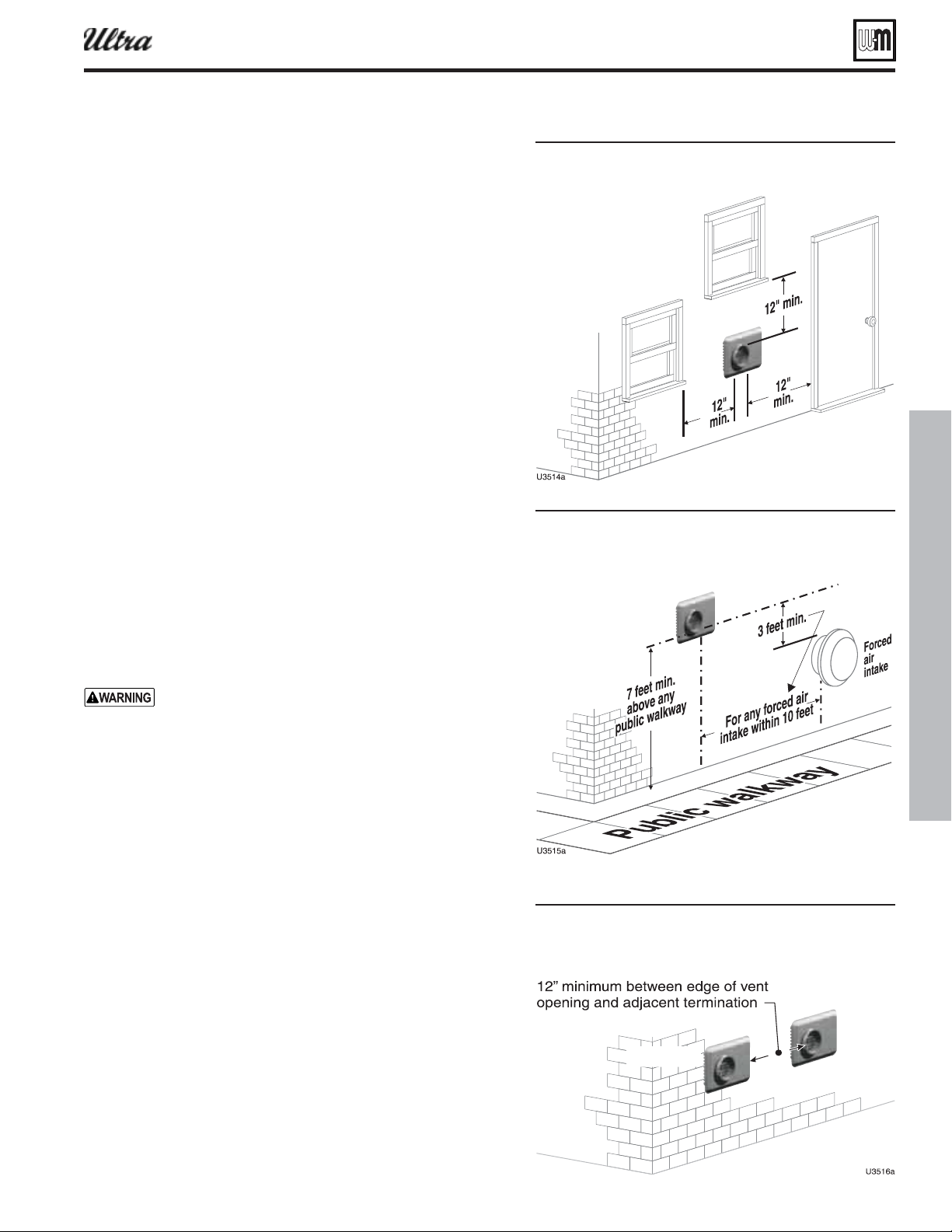
Part number 550-100-400/0119
69
d. Avoid possibility of accidental contact of fl ue products with
people or pets.
e. Do not locate the terminations where wind eddies could affect
performance or cause recirculation, such as inside building
corners, near adjacent buildings or surfaces, window wells,
stairwells, alcoves, courtyards or other recessed areas.
f. Do not terminate above any door or window or under a deck.
Condensate can freeze, causing ice formations.
g. Locate or guard vent to prevent condensate damage to exterior
fi nishes.
3. Maintain clearances as shown in Figure 70, page 68 , Figure 71 ,
Figure 71 and Figure 73 . Also maintain the following:
a. Vent must terminate:
At least 6 feet from adjacent walls.
No closer than 5 feet below roof overhang.
At least 7 feet above any public walkway.
At least 3 feet above any forced air intake within 10 feet.
No closer than 12 inches below or horizontally from any
door or window or any other gravity air inlet.
b. Air inlet must terminate at least 12” above grade or snow line
c. Do not terminate closer than 4 feet horizontally (above or
below) from any electric meter, gas meter, regulator, relief
valve or other equipment.
4. Locate terminations so they are not likely to be damaged by
foreign objects, such as stones or balls, or subject to buildup of
leaves or sediment.
Multiple vent/air terminations
1. When terminating multiple Ultra boilers, terminate each vent/air
connection as described in this manual.
All vent pipes and air inlets must terminate at the same
height to avoid possibility of severe personal injury,
death or substantial property damage.
2. Place wall penetrations to obtain minimum clearance as shown
in Figure 73 for U. S. installations. For Canadian installations,
provide clearances required by Natural Gas and Propane Instal-
lation
CAN/CSA
B149.1 or B149.2 Installation Code.
3. The air inlet of an Ultra boiler is part of a direct vent connection.
It is not classifi ed as a forced air intake with regard to spacing
from adjacent boiler vents.
4. Combustion air (NOT vent piping) can be manifolded as shown
in Figure 59, page 59 .
®
Series 4
gas-fired water boiler — Boiler Manual
Figure 71 Termination location eil-cLain ent
air plate clearances to openins
Figure 72Termination location eil-cLain ent
air plate clearances to pulic ala or
forced air intae
Figure 73 Termination location eil-cLain ent
air plate multiple oilers clearance from
ent to air intae of the net oiler
Sidewall vent/air termination: Weil-McLain cap (cont.)
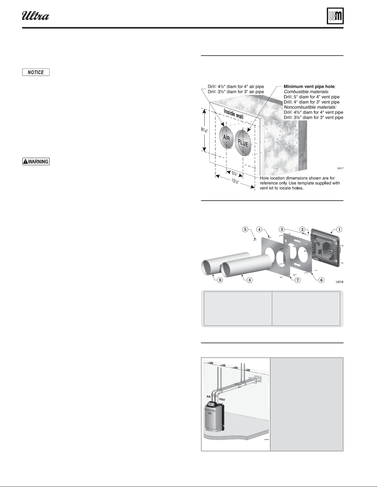
Part number 550-100-400/0119
70
Figure 74 ole preparation in all eil-cLain ent
air plate
Figure 75 Termination asseml eil-cLain ent
air plate
1 Vent termination (3” or 4”)
2 Lock washer, #10 (4)
3 Sheet metal screw, #10 x ½” (4)
4 Plastic wall anchor (8)
5 Sheet metal screw, #10 x 1¼” (8)
6 Outer mounting plate
7 Inner mounting plate
8 Vent pipe (butt to screen in termina-
tion)
9 Air pipe (butt to stops in termina-
tion)
Figure 76 Install termination plate
Install pipe supports every 5
feet on both the horizontal and
vertical runs.
Install a hanger support within
6 inches of any upturn in the
piping.
The Weil-McLain plate
termination must be installed
before piping from the boiler to
the termination.
Slope horizontal piping
downward toward the boiler at
least 1/4 inch per foot.
®
Series 4
gas-fired water boiler — Boiler Manual
Sidewall vent/air termination: Weil-McLain cap (cont.)
Install terminations — Weil-McLain vent/air cap
The inside and outside cover plates are stamped to
identify the exhaust (vent) and intake (air) openings.
Make sure to orient the plates correctly.
1. Locate termination opening and avoid obstructions:
a. Use the template supplied with the termination kit.
b. Locate the template on the outside building surface where
the penetration is to be made.
c. Make sure there will be no obstructions that might prevent
proper placement of the termination.
d. Use the template to mark the locations for the four mount-
ing holes, fl ue pipe and air pipe. Level the template with a
spirit level.
For the Weil-McLain plate, the template must be level
to ensure the fl ue and air pipe will be side-to-side, as
shown in Figure 74 . Failure to comply could result in
severe personal injury, death or substantial property
damage.
e. Cut holes in the wall as shown in Figure 75 , using the location
marks made with the template. For best results, use a small-
diameter, long drill bit to drill centering holes for the fl ue and
air pipe openings. Then drill the large openings from both
the inside and outside.
f. The fl ue pipe and air pipe may be run through a rectangular
cutout (as marked on the template) in lieu of two separate
holes if desired.
2. Drill holes for the screws or plastic anchors to secure the outside
plate. Install the outside plate and mount the termination on the
plate (temporarily).
a. Cut the fl ue pipe so the extension through the wall will cause
the vent pipe to fully extend into the termination socket.
b. Cut the air pipe so the extension through the wall will butt
the air pipe against the stops inside the termination.
c. When using 3-inch vent piping with a 4-inch termination
(Ultra-230 applications), increase the fl ue pipe size to 4 inch
before the pipe passes through the wall. This is required to
obtain a seal between the fl ue pipe and the termination.
d. Temporarily slide the flue and air pipes through the
opening(s). Slide the inside wall plate over the two pipes and
into position on the inside wall.
e. Position the inside plate so the fl ue pipe and air pipe slope
downward slightly toward the boiler (1/4” per foot).
f. Mark the four (4) mounting holes for the plate.
g. Remove the vent and air pipe, drill the four mounting holes,
and mount the inside plate.
3. Test fi t the vent/air termination on the vent pipe. Make sure the
vent pipe fully penetrates the termination socket and the air pipe
butts against the interior stops.
4. Apply silicon RTV sealant to the interior of the vent termination
and slide onto vent pipe. Rotate slightly to spread the silicon to
ensure a tight seal around the vent pipe.
5. Secure the termination in place using the four (4) #10 x ½” sheet
metal screws and lock washers (see Figure 75 ).
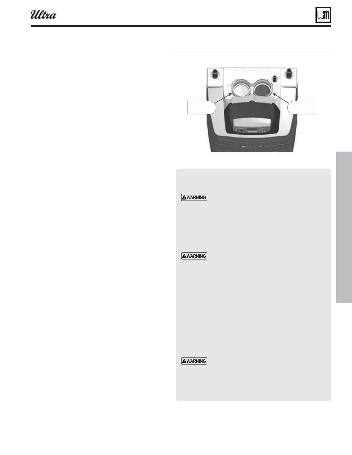
Part number 550-100-400/0119
71
Install vent/air piping — boiler to W-M termination
Figure 77 Boiler ent and air connections
"JSQJQF
DPOOFDUPS
7FOUQJQF
DPOOFDUPS
6
Inserting/securing vent or air pipe into
boiler connectors
AL29-4C vent pipe — If using AL29-4C stainless
vent pipe, you must install a PVC-to-vent pipe
adapter at the boiler vent connection (and at the
termination if using the Weil-McLain plate or the
concentric termination). Use only the adapter made
by the vent pipe manufacturer.
1. PVC/ABS pipe — Clean and chamfer insertion end of pipe.
Deburr inside of insertion end. Clean and deburr inside and
outside of other end of pipe.
The pipe end must be smooth and chamfered to
prevent possible damage to sealing gasket in vent
or air pipe adapter. Failure to comply could result
in leakage, causing possible severe personal injury
or death.
2. Inspect vent or air adapter (above) — verify no obstructions
or foreign objects inside.
3. Loosen clamp screw.
4. Measure 3½ inches from end of pipe and make a mark with
felt-tip pen.
5. Loosen adapter clamp screw.
6. Apply small amount of silicon grease to end of pipe to ease
insertion.
7. Insert pipe into adapter.
8. Slide pipe down until the 3½-inch mark is reached.
Do not apply excessive force or bend the adapter
or fl ue/air pipe when inserting. The adapter or seal
could be damaged.
9. Secure vent or air pipe by tightening the adapter clamp se-
curely. Do not overtighten. The seal is accomplished with the
internal gasket. The clamp is only to hold the pipe in place.
®
Series 4
gas-fired water boiler — Boiler Manual
Complete termination preparation
1. Install vent and air terminations before proceeding.
See previous pages for instructions.
Installing vent and air piping
1. For reference in the following, see previous pages.
2. Work from the boiler to vent or air termination. Do not
exceed the lengths given in the previous pages for either
the air or vent piping.
a. As shown in the maximum length tables, the
Ultra-80 or Ultra-105 may be installed with either
2-inch or 3-inch vent and air piping.
b. As shown in the maximum length tables, the
Ultra-230 may be installed with either 3-inch or
4-inch vent and air piping.
c. You must install appropriate pipe reducers, where
required, at both the boiler and at the termination
assembly.
3. See Figure 77 for attaching vent and air pipes at the
boiler.
4. Cut pipe to required lengths.
5. Deburr inside and outside of pipe ends.
6. Chamfer outside of each pipe end to ensure even cement
distribution when joining.
7. Clean all pipe ends and fi ttings. Dry thoroughly.
8. Dry assemble entire vent or air piping to ensure proper
fi t before assembling any joint.
9. For each joint:
a. Handle fi ttings and pipes carefully to prevent con-
tamination of surfaces.
b. Apply primer liberally to both joint surfaces — pipe
end and fi tting socket.
c. While primer is still damp, lightly apply approved
cement to both surfaces in a uniform coating.
d. Apply a second coat to both surfaces. Avoid using
too much cement on sockets to prevent cement
buildup inside.
e. With cement still wet, insert pipe into fi tting, twist-
ing ¼ turn. Make sure pipe is fully inserted.
f. Wipe excess cement from joint. Check joint to be
sure a smooth bead of cement shows around the
entire joint.
10. Install pipe supports as shown in Figure 76, page 70 .
11. Slope vent and air piping continuously toward boiler,
with at least 1/4 inch drop per foot of run. Do not allow
sags at any point.
12. Maintain minimum clearance of
3/16 inch between vent
pipe and any combustible wall or material.
13. Seal wall or fl oor penetration openings following local
code requirements.
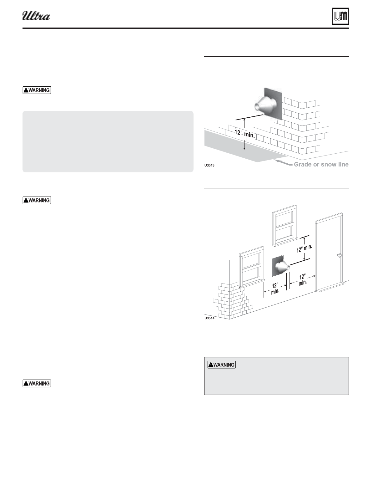
Part number 550-100-400/0119
72
®
Series 4
gas-fired water boiler — Boiler Manual
Sidewall vent/air termination: 3” or 4” concentric
Termination kit — 3” or 4” concentric termination
1. The 3” or 4” concentric termination kit must be purchased sepa-
rately. See below.
Use only the vent materials and kits listed in Fig-
ure 12, page 18 for concentric venting. Provide pipe
adapters as specifi ed in Figure 12, page 18 .
Commonwealth of Massachusetts
When the boiler is installed within the Commonwealth of Mas-
sachusetts:
This product must be installed by a licensed plumber or gas
fi tter.
See instruction in the Boiler manual.
Allowable vent/air pipe materials
Use only the materials listed in Figure 13, page 19 .
Maximum piping length
1. Locate the termination such that the total air piping and vent piping
from the boiler to the termination will not exceed the maximum
length given in Figure 12, page 18 .
2. Maximum lengths listed in Figure 12, page 18 allow for 1 elbow.
Additional elbows required a reduction in maximum length as
explained in the table notes.
Connecting from termination to boiler
1. Install the termination as instructed in the following.
2. Then proceed to page 82 to complete the air and vent piping be-
tween the termination and the boiler.
3. The center lines between the air and vent are wider at the
concentric termination connections than at the boiler. See
Figure 87, page 77 for suggestions on adjusting the spacing when
required. In addition to the method given there, you can rotate the
Y-fi tting slightly, which will cause the air pipe to be slightly higher
or lower than the vent, but the center lines will match those at the
boiler vent and air connections.
Determine locations for terminations
A gas vent extending through an exterior wall shall not
terminate adjacent to the wall or below building exten-
sions such as eaves, parapets, balconies or decks. Failure
to comply could result in severe personal injury, death
or substantial property damage.
Locate the vent/air terminations using the following guidelines.
1. You must consider the surroundings when terminating the vent
and air:
a. Position the vent termination where vapors will not damage
nearby shrubs, plants or air conditioning equipment or be
objectionable.
Figure 78 Termination location or concentric
termination heiht aoe rade or sno
line
Figure 79 Termination location or concentric
termination clearances to openins
All vent and air pipes require a
. Most kits do not
include the screens. Purchase separately
from Weil-McLain or vent kit supplier if
not included.
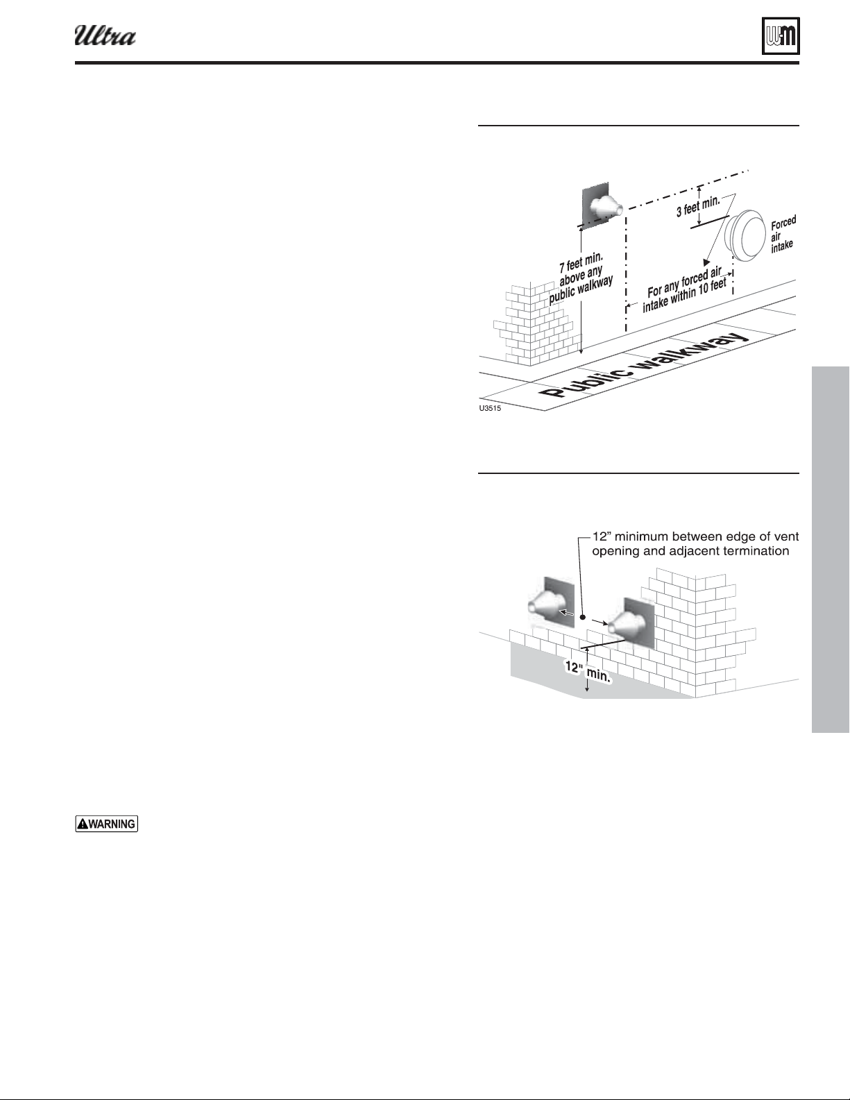
Part number 550-100-400/0119
73
®
Series 4
gas-fired water boiler — Boiler Manual
Sidewall vent/air termination: 3” or 4” concentric (cont.)
b. The fl ue products will form a noticeable plume as they con-
dense in cold air. Avoid areas where the plume could obstruct
window views.
c. Prevailing winds could cause freezing of condensate and water/
ice buildup where fl ue products impinge on building surfaces
or plants.
d. Avoid possibility of accidental contact of fl ue products with
people or pets.
e. Do not locate the terminations where wind eddies could affect
performance or cause recirculation, such as inside building
corners, near adjacent buildings or surfaces, window wells,
stairwells, alcoves, courtyards or other recessed areas.
f. Do not terminate above any door or window or under a deck.
Condensate can freeze, causing ice formations.
g. Locate or guard vent to prevent condensate damage to exterior
fi nishes.
2. Maintain clearances as shown in Figure 78 , Figure 79 , Figure 80
and Figure 81 . Also maintain the following:
a. Vent must terminate:
At least 6 feet from adjacent walls.
No closer than 5 feet below roof overhang.
At least 7 feet above any public walkway.
At least 3 feet above any forced air intake within 10 feet.
No closer than 12 inches below or horizontally from any
door or window or any other gravity air inlet.
b. Air inlet must terminate at least 12” above grade or snow line.
c. Do not terminate closer than 4 feet horizontally (above or be-
low) from any electric meter, gas meter, regulator, relief valve
or other equipment.
3. Locate terminations so they are not likely to be damaged by foreign
objects, such as stones or balls, or subject to buildup of leaves or
sediment.
Multiple vent/air terminations
1. When terminating multiple Ultra boilers, terminate each vent/air
connection as described in this addendum.
All vent pipes and air inlets must terminate at the same
height to avoid possibility of severe personal injury, death
or substantial property damage.
2. Place wall penetrations to obtain minimum clearance as shown in
Figure 81 for U. S. installations. For Canadian installations, provide
clearances required by CSA B149.1 or B149.2 Installation Code.
3. The air inlet of an Ultra boiler is part of a direct vent connection.
It is not classifi ed as a forced air intake with regard to spacing from
adjacent boiler vents.
4. Combustion air (NOT vent piping) can be manifolded as shown
in Boiler manual, page 55.
Figure 80 Termination location or concentric
termination clearances to pulic ala
or forced air intae
Figure 81 Termination location or concentric
termination multiple oilers clearance
from ent of one to air intae of the net
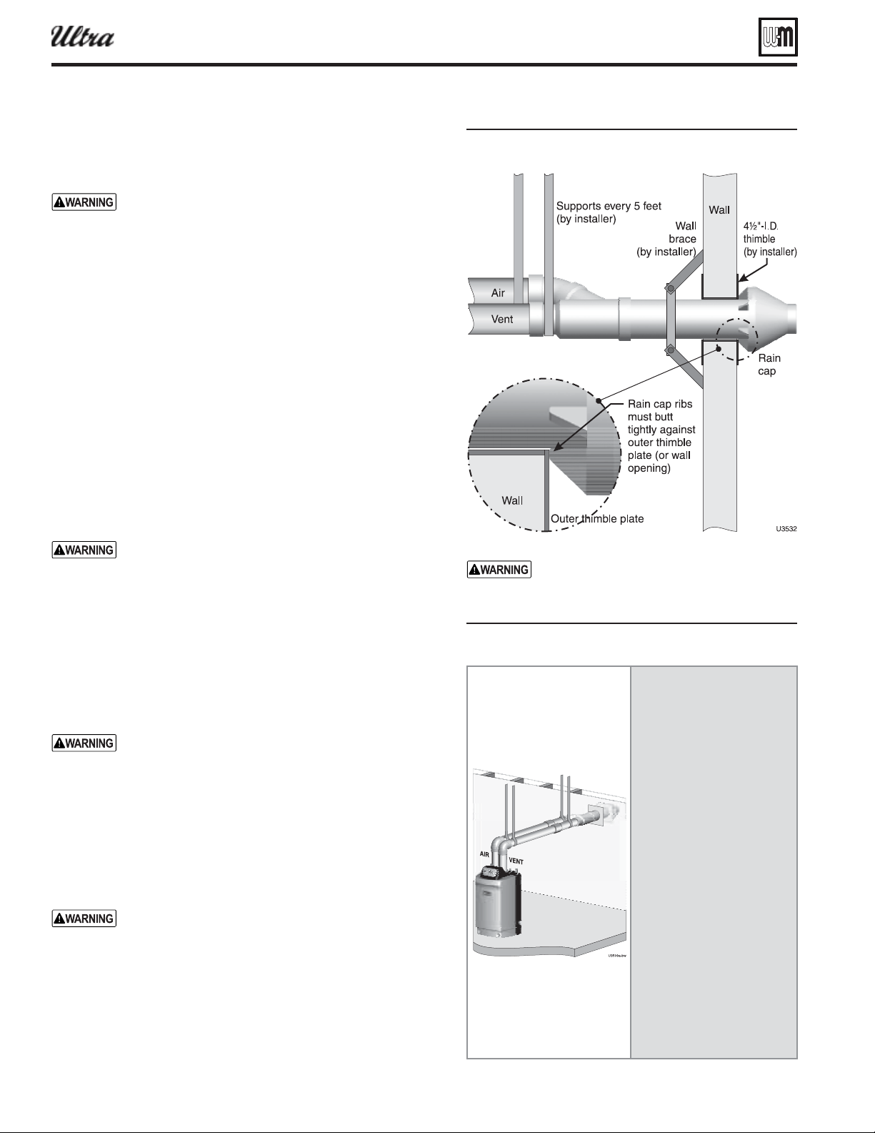
Part number 550-100-400/0119
74
Sidewall vent/air termination: 3” or 4” concentric (cont.)
®
Series 4
gas-fired water boiler — Boiler Manual
Figure 82 Installin and supportin the concentric
sideall ent asseml
Figure 83
Ensure that the wall material is strong enough
to prevent the rain cap from being pushed
inward if struck or pushed from the outside.
Install terminations — concentric pipes
1. Assemble the vent termination as described for vertical concen-
tric terminations, beginning on page 76 .
If necessary, you can shorten the lengths of the inner
and outer pipes for a shorter fi nished assembly. But
you must ensure the pipes butt correctly at both ends.
Failure to properly assemble the concentric termina-
tion can result in fl ue gas recirculation, causing possible
severe personal injury or death.
2. Wall penetration:
a. 3” termination: Preferably, use a thimble with a 4½-inch
hole. If not using a thimble, carefully use a hole saw to cut a
hole not larger than 4¾ inches in diameter through the wall.
The fi nished hole must provide a solid stop for the rain cap
ribs, as shown in the inset to Figure 82 .
b. 4” termination: Preferably, use a thimble with a 6-inch hole.
If not using a thimble, carefully use a hole saw to cut a hole
not larger than 6¼ inches in diameter through the wall. The
fi nished hole must provide a solid stop for the rain cap ribs,
as shown in the inset to Figure 82 .
3. Secure the termination in place so the rain cap will butt against
the outside wall or outer thimble plate as shown in Figure 82 .
4. Before beginning vent and air piping from the boiler to the
concentric termination, mount and secure the concentric ter-
mination as shown in Figure 82 and Figure 105 .
The vent and air piping must be securely supported,
and must not rest its weight on the boiler fi ttings. Fail-
ure to properly support the vent and air piping could
result in vent piping damage, resulting in possible
severe personal injury, death or substantial property
damage.
The supports/bracing used must support the termina-
tion assembly to prevent slippage or movement.
The clamps used on the outside of the termination pipe
must not cut into the pipe or contain sharp edges that
could cause a crack to form.
When inserting the partially-assembled termination
kit through the roof penetration, wrap plastic or
other protection over the end of the exposed assembly
to prevent debris from entering the pipes. If the air
passages become blocked, the boiler will not operate.
Once the rain cap has been cemented to the assembly,
there is no way to correct the problem. The assembly
would have to be replaced if it were cut to be removed
and cleaned. Altering the assembly in any way could
result in severe personal injury or death due to toxic
fl ue product emissions.
When using AL29-4C stainless vent pipe, use the vent
pipe manufacturer’s PVC adapter when connecting to
the concentric vent attachment.
5. After the assembly has been positioned in the opening and all
supports have been attached, install a bird screen (purchased
separately if not included with the kit) and rain cap as follows:
a. Place the bird screen on the end of the inner pipe as in Fig-
ure 89, page 78 .
b. Cement the rain cap in place as shown.
installin termination see
pae
Install pipe supports every 5 feet
on both the horizontal and verti-
cal runs.
Install a hanger support within
6 inches of any upturn in the
piping.
Support the termination
at the wall as shown in the
termination instructions.
Slope horizontal piping
downward toward the boiler at
least 1/4 inch per foot.
Rotate the concentric
termination Y-fi tting about
30° to result in pipe centers the
same as at the boiler.
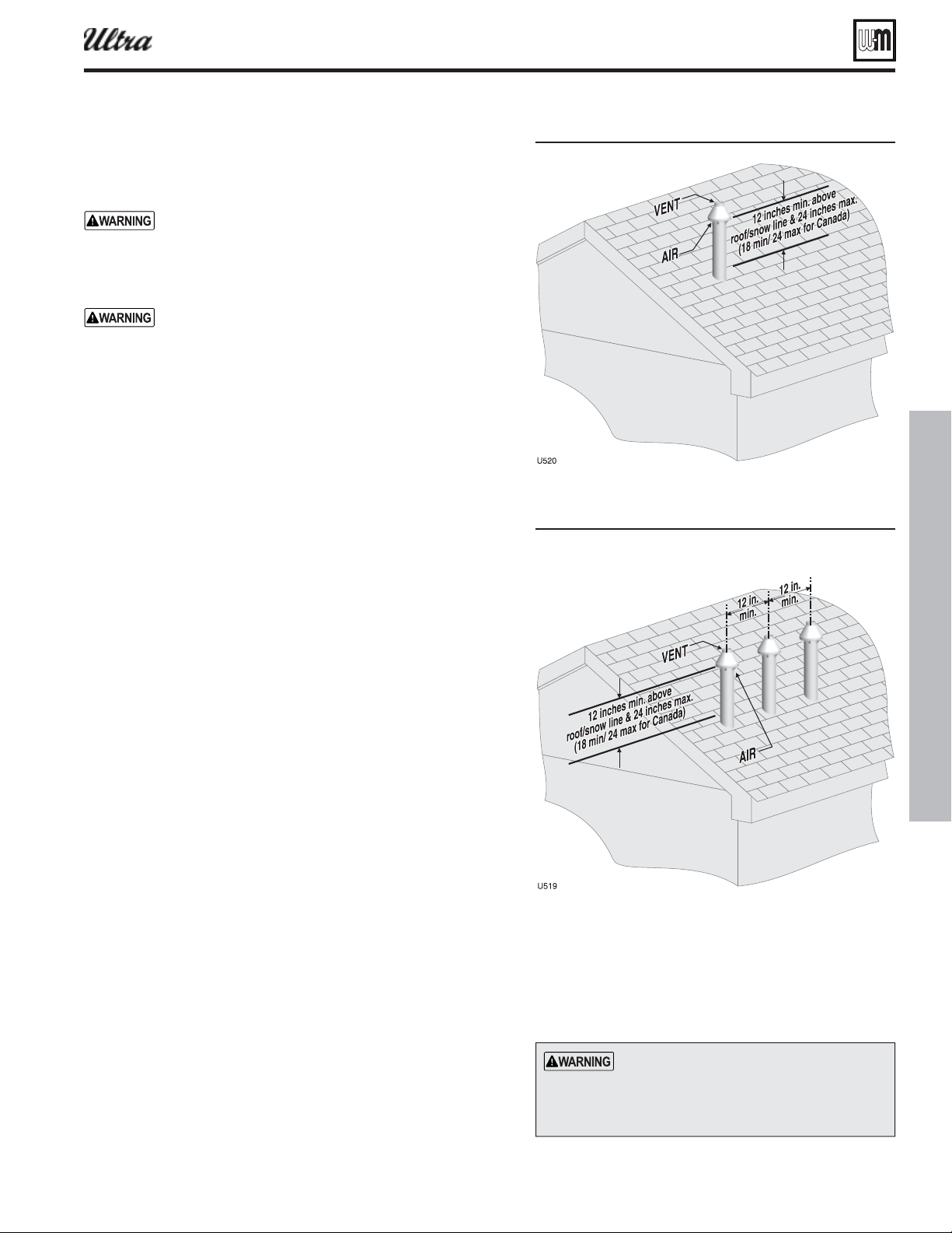
Part number 550-100-400/0119
75
Vertical vent/air termination: 3” or 4” concentric
®
Series 4
gas-fired water boiler — Boiler Manual
Termination kit — 3” or 4” concentric termination
1. The 3” or 4” concentric termination kit must be purchased sepa-
rately. See below.
Use only the vent materials and kits listed in Fig-
ure 12, page 18 for concentric venting. Provide pipe
adapters as specifi ed in Figure 12, page 18 .
Allowable vent/air pipe materials
Use only the materials listed in Figure 13, page 19 .
Maximum piping length
1. Locate the termination such that the total air piping and vent piping
from the boiler to the termination will not exceed the maximum
length given in Figure 12, page 18 .
2. Maximum lengths listed in Figure 12, page 18 allow for 1 elbow.
Additional elbows required a reduction in maximum length as
explained in the table notes.
Connecting from termination to boiler
1. Install the termination as instructed in the following. Then pro-
ceed to page 82 to complete the piping between the termination
and the boiler.
Determine location
Locate the concentric vent/air termination using the following guide-
lines:
1. The concentric vent/air assembly must terminate as shown in
Figure 84 .
2. The vent and air piping connected to the termination assembly
must comply with the instructions in this supplement.
3. You must consider the surroundings when terminating the vent
and air:
a. Position the termination where vent vapors will not damage
nearby shrubs, plants or air conditioning equipment or be
objectionable.
b. The fl ue products will form a noticeable plume as they con-
dense in cold air. Avoid areas where the plume could obstruct
window views.
c. Prevailing winds could cause freezing of condensate and water/
ice buildup where fl ue products impinge on building surfaces
or plants.
d. Avoid possibility of accidental contact of fl ue products with
people or pets.
e. Do not locate the termination where wind eddies could affect
performance or cause recirculation, such as inside building
corners, near adjacent buildings or surfaces, window wells,
stairwells, alcoves, courtyards or other recessed areas.
f. Locate or guard vent outlet to prevent condensate damage to
exterior fi nishes.
4. Maintain clearances to termination as given below:
a. Vent outlet must be located:
Figure 84ertical termination or concentric
Figure 85ertical termination or concentric
multiple oilers
All vent and air pipes require a
. Most kits do not
include the screens. Purchase separately
from Weil-McLain or vent kit supplier if
not included.
Part number 550-100-400/0119
76
®
Series 4
gas-fired water boiler — Boiler Manual
At least 6 feet from adjacent walls.
No closer than 5 feet below roof overhang.
At least 7 feet above any public walkway.
At lease 3 feet above any forced air intake within
10 feet.
No closer than 12 inches below or horizontally from any
door or window or any other gravity air inlet.
b. Air inlet must terminate at least 12 inches above the
roof or snow line as shown in Figure 84, page 75 .
(For Canada, the minimum is 18 inches.)
c. Do not terminate closer than 4 feet horizontally from any
electric meter, gas meter, regulator, relief valve or other
equipment. Never terminate above or below any of these
within 4 feet horizontally.
5. Locate termination so it is not likely to be damaged by for-
eign objects, such as stones or balls, or subject to buildup of
leaves or sediment.
6. Do not connect any other appliance to the vent pipe or mul-
tiple boilers to a common vent pipe.
Multiple vent/air terminations
1. When terminating multiple Ultra boilers, install the con-
centric vent/air termination assemblies as described in this
addendum.
All vent outlets must terminate at the same height
to avoid possibility of severe personal injury, death
or substantial property damage.
2. Place roof penetrations to obtain minimum of 12 inches
between centers of adjacent vent pipe of another boiler for
U. S. installations (see Figure 85, page 75 ).
3. For Canadian installations, provide clearances required by
CSA B149.1 or B149.2 Installation Code.
4. The air inlet of an Ultra boiler is part of a direct vent con-
nection. It is not classifi ed as a forced air intake with regard
to spacing from adjacent boiler vents.
Prepare roof penetrations
1. Roof penetration hole:
a. 3” termination: Cut a 5-inch diameter hole to clear the
4½-inch termination outside diameter.
b. 4” termination: Cut a 6.5-inch diameter hole to clear the
6-inch termination outside diameter.
c. Insert a galvanized metal thimble in the vent pipe hole.
2. Follow all local codes for isolation of vent pipe when passing
through fl oors, ceilings and roofs.
3. Provide fl ashing and sealing boots sized for the concentric
termination outside diameter.
Assembling the concen tric termination
1. See Figure 89, page 78 for the dimensions and details of the
termination assembly.
2. Prepare the bird screen (purchased separately if not included
with the kit). Cut the bird screen to size if required. If the
bird screen must be trimmed, cut the bird screen to fi t the
outside diameter of the PVC inner pipe supplied with the
termination kit.
3. Partially assemble the vent termination kit in the sequence
shown in Figure 89, page 78 .
install the rain cap and bird screen until
the assembly has been inserted through the roof
and all supports have been installed. Follow instruc-
tions to cover the end of the assembly with plastic
before inserting through the roof penetration to
prevent debris from blocking the air passages.
4. Use the following procedures to prepare termination com-
ponents and cement together.
5. Deburr inside and outside of pipe ends.
6. Chamfer outside of each pipe end to ensure even cement
distribution when joining.
7. Clean all pipe ends and fi ttings.
8. Dry thoroughly.
9. Dry assemble entire vent or air piping to ensure proper fi t
before assembling any joint.
10. For each joint:
a. Handle fi ttings and pipes carefully to prevent contamina-
tion of surfaces.
b. Apply primer liberally to both joint surfaces — pipe end
and fi tting socket.
c. While primer is still damp, lightly apply approved cement
to both surfaces in a uniform coating.
d. Apply a second coat to both surfaces. Avoid using too
much cement on sockets to prevent cement buildup
inside.
e. With cement still wet, insert pipe into fi tting, twisting
¼ turn. Make sure pipe is fully inserted.
If necessary, you can shorten the lengths of the inner
and outer pipes for a shorter fi nished assembly. But
you must ensure the pipes butt correctly at both
ends. Failure to properly assemble the concentric
termination can result in fl ue gas recirculation,
causing possible severe personal injury or death.
Mount concentric termination
1. Before beginning vent and air piping from boiler, mount
and secure the concentric termination as shown in Fig-
ure 106, page 92 , and Figure 88, page 77 .
The vent and air piping must be securely supported,
and must not rest its weight on the boiler fi ttings.
DO NOT drill or screw into either the vent pipe
or air pipe. Failure to properly support the vent
and air piping could result in vent piping damage,
resulting in possible severe personal injury, death
or substantial property damage.
Vertical vent/air termination: 3” or 4” concentric (cont.)
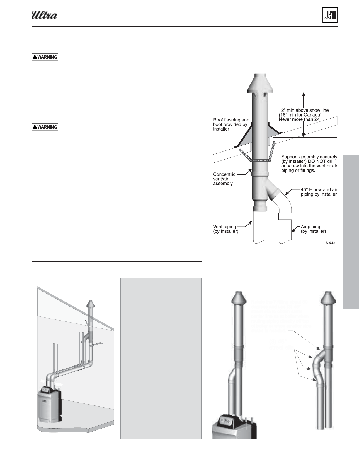
Part number 550-100-400/0119
77
®
Series 4
gas-fired water boiler — Boiler Manual
When inserting the partially-assembled termination kit
through the roof penetration, wrap plastic or other protection
over the end of the exposed assembly to prevent debris from
entering the pipes. If the air passages become blocked, the
boiler will not operate. Once the rain cap has been cemented
to the assembly, there is no way to correct the problem. The as-
sembly would have to be replaced if it were cut to be removed
and cleaned. Altering the assembly in any way could result
in severe personal injury or death due to toxic fl ue product
emissions.
When using AL29-4C stainless vent pipe, use the vent pipe
manufacturer’s PVC adapter when connecting to the con-
centric vent attachment.
1. After the assembly has been positioned in the roof opening and all sup-
ports have been attached, install a bird screen (purchased separately if
not included with the kit) and rain cap as follows:
a. Place the bird screen on the end of the inner pipe as in
Figure 89, page 78 .
b. Cement the rain cap in place as shown.
Vent termination support
1. Support the concentric vent/air termination at the roof penetration
as shown in Figure 88 .
The supports/bracing used must support the termination assembly
to prevent vertical slippage or sideways movement.
The clamps used on the outside of the termination pipe must not
cut into the pipe or contain sharp edges that could cause a crack
to form.
Figure 86
6CX
7&/5
"*3
installin termination see pae
Install pipe supports every 5 feet on
both the horizontal and vertical runs.
Install a hanger support within
6 inches of any upturn in the piping.
.
Support the termination at the ceiling
and above the roof as shown in the
termination instructions.
Slope horizontal piping downward
toward the boiler at least 1/4 inch per
foot.
Use long-radius elbows for air piping
when using 2” or 3” pipe to reduce
pressure drop.
Rotate the concentric termination
Y-fi tting about 30° to result in pipe
centers the same as at the boiler.
Figure 87 or concentric termination supports
Vertical vent/air termination: 3” or 4” concentric (cont.)
Figure 88 Alternate pipin con uration usin
-deree elos to otain closer pipe
centers
6
3PUBUFUIF:GJUUJOHBCPVU
EFHSFFTBOEVTF
TUSFFUFMMTUPPCUBJOTBNF
DFOUFSMJOFBTBUCPJMFSXIFO
SPVUJOHQJQJOHEJSFDUMZPGGUPQ
PGCPJMFSPSXIFOTNBMMFSQJQF
DIBTFJTOFFEFE
TUSFFMFMMT

Part number 550-100-400/0119
78
®
Series 4
gas-fired water boiler — Boiler Manual
Concentric vent/air termination assembly
Figure 89 or concentric termination asseml
O NOT attach the rain cap until the
termination has een inserted throuh the
roof or all and all supports hae een
installed.
Figure 90 or concentric termination asseml see it
manufacturers instructions for details
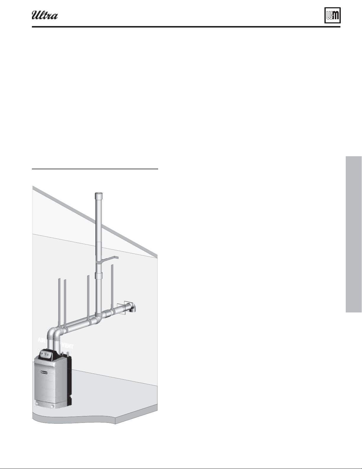
Part number 550-100-400/0119
79
®
Series 4
gas-fired water boiler — Boiler Manual
DIRECT VENT: Vertical vent / sidewall air
Determine location
1. Locate the vent termination using the following guidelines:
2. The vent piping must terminate in an up-turned coupling as shown
in Figure 92, page 80 . The top of the coupling must be at least 1 foot
above the air intake.
3. You must consider the surroundings when terminating the vent and air:
a. Position the vent termination where vapors will not damage nearby
shrubs, plants or air conditioning equipment or be objectionable.
b. The fl ue products will form a noticeable plume as they condense in
cold air. Avoid areas where the plume could obstruct window views.
c. Prevailing winds could cause freezing of condensate and water/ice
buildup where fl ue products impinge on building surfaces or plants.
d. Avoid possibility of accidental contact of fl ue products with people
or pets.
e. Do not locate the terminations where wind eddies could affect
performance or cause recirculation into building or appliance air
intakes, such as inside building corners, near adjacent buildings
or surfaces, window wells, stairwells, alcoves, courtyards or other
recessed areas.
f. Do not terminate above any door or window. Condensate can freeze,
causing ice formations.
g. Locate or guard vent to prevent condensate damage to exterior
fi nishes.
4. Maintain clearances to vent termination as given below:
a. Vent must terminate:
At least 6 feet from adjacent walls.
No closer than 5 feet below roof overhang.
At least 3 feet above any forced air intake within 10 feet.
No closer than 12 inches below or horizontally from any door
or window or any other gravity air inlet.
b. Do not terminate vent closer than 4 feet horizontally from any
electric meter, gas meter, regulator, relief valve or other equip-
ment. Never terminate above or below any of these within 4 feet
horizontally.
5. Locate terminations so they are not likely to be damaged by foreign ob-
jects, such as stones or balls, or subject to buildup of leaves or sediment.
6. Do not connect any other appliance to the vent pipe. Do not connect
multiple boilers to a common vent pipe.
Prepare roof penetrations
1. Vent pipe penetration:
a. Cut a hole for the vent pipe. For either combustible or noncombus-
tible construction, size the vent pipe hole at least 0.4” larger than
the vent pipe diameter:
2¾” hole for 2”
4” hole for 3”
5” hole for 4”
b. Insert a galvanized metal thimble in the vent pipe hole.
2. Follow all local codes for isolation of vent pipe when passing through
fl oors, ceilings and roofs.
3. Provide fl ashing and sealing boots sized for the vent pipe and air pipe.
Allowable vent/air pipe materials
1. Use only the materials listed in Figure 13, page 19 .
2. Purchase bird screens for vent and air termina-
tions separately. See the parts list at the end of this
manual.
Maximum piping lengths
1. Locate the terminations such that the total air pip-
ing and vent piping from the boiler to the termina-
tion will not exceed the maximum length given in
Figure 12, page 18 .
2. Maximum lengths listed in Figure 12, page 18 allow
for 1 elbow in the air piping and 1 elbow in the vent
piping. Additional elbows required a reduction in
maximum length as explained in the table notes.
Figure 91
674CX
7&/5
"*3
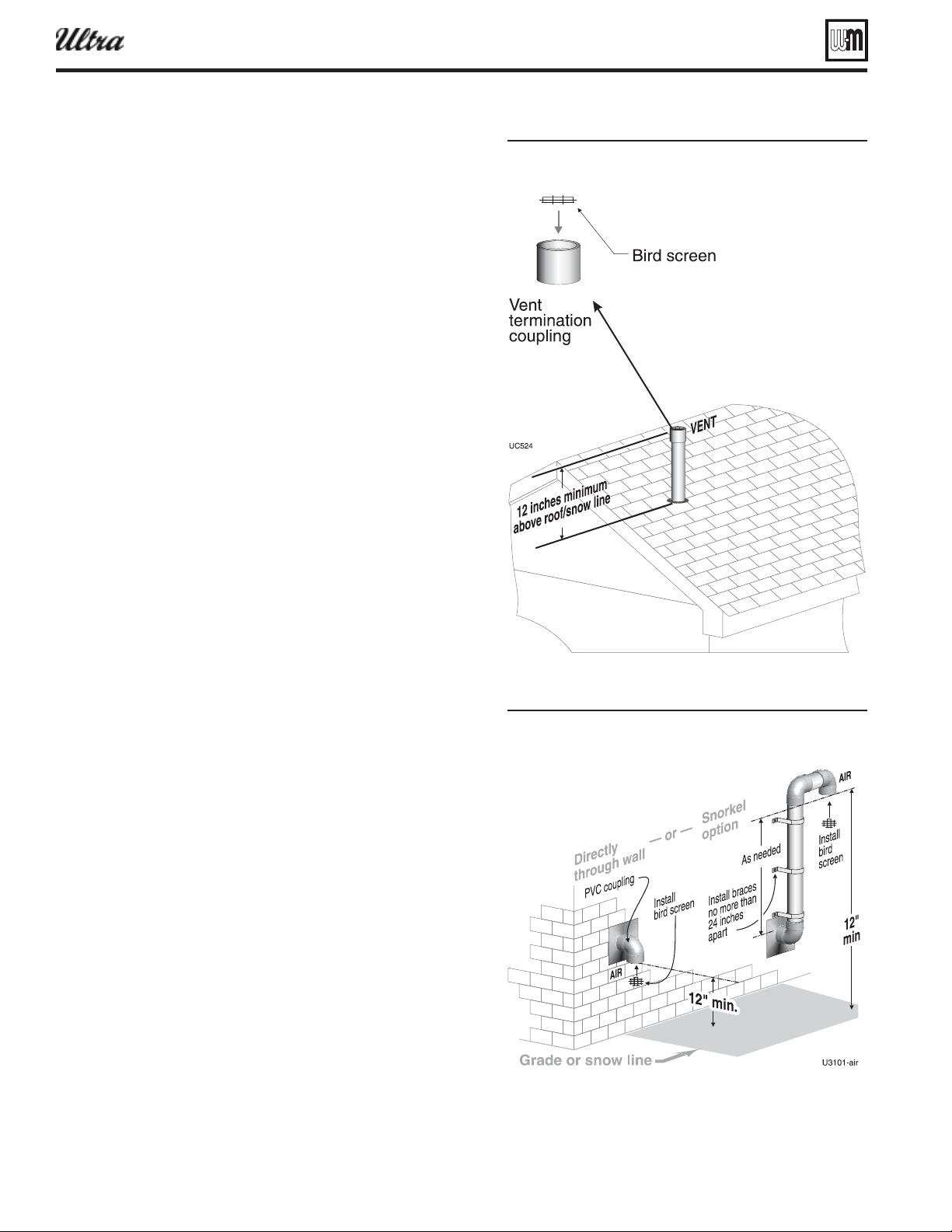
Part number 550-100-400/0119
80
®
Series 4
gas-fired water boiler — Boiler Manual
DIRECT VENT: Vertical vent / sidewall air (continued)
Termination and fi ttings
1. Prepare the vent termination coupling by inserting a bird screen.
Bird screens must be purchased separately. See the parts list at the
end of this manual for part numbers.
a. If using 3-inch piping for an Ultra-230, cut a 4-inch bird screen
by placing 3-inch fi tting on screen and cutting around it as a
template.
2. Maintain the required dimensions of the fi nished termination
piping as shown in Figure 92 .
Multiple vent terminations
1. When terminating multiple Ultra boilers, terminate each vent/air
connection as described in this section.
2. Place adjacent terminations at least 6 inches apart.
3. For Canadian installations, provide clearances required by CSA
B149.1 or B149.2 Installation Code.
Connecting from vent termination to boiler
1. Install the termination penetration as instructed in the preced-
ing. Then proceed to page 82 to complete the piping between the
termination and the boiler.
Determine location for air inlet elbow
1. The air inlet of an Ultra boiler is part of a direct vent connection.
It is not classifi ed as a forced air intake with regard to spacing from
adjacent appliance terminations.
2. Locate the air inlet elbow (termination) using the following
guidelines.
3. The air piping must terminate in a down-turned elbow as shown
in Figure 93 .
a. Apply the confi guration on the left side of Figure 93 unless
the terminations would fail to meet minimum clearance to
grade or snow line.
b. Apply the confi guration on the right side of Figure 93 when
the terminations need to be raised higher to meet clearance to
grade or snow line.
c. The air pipe may run up the side of the building, as shown.
The vent and air pipes must be secured with braces, and all
clearances and lengths must be maintained. Space braces no
further than 24 inches apart.
4. You must consider the surroundings when terminating the air
connection:
a. Make sure there are no obstructions for air fl ow. DO NOT
locate the termination where plants could grow and cause
obstruction to air fl ow.
b. Do not locate the terminations where wind eddies could affect
performance or cause recirculation with exhaust from other
appliances, such as inside building corners, near adjacent build-
ings or surfaces, window wells, stairwells, alcoves, courtyards
or other recessed areas.
c. Locate the air inlet termination at least 12 inches below and 12
inches horizontally from any appliance or building vent outlet.
5. Locate terminations so they are not likely to be damaged by foreign
objects, such as stones or balls, or subject to buildup of leaves or
sediment.
Figure 92 ent termination throuh the roof for direct
ent ertical ent sideall air
Figure 93 Sideall air inlet termination for direct ent
ertical ent sideall air
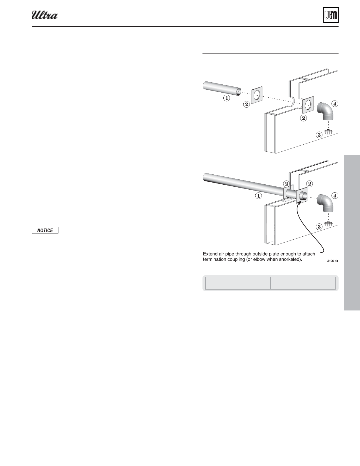
Part number 550-100-400/0119
81
®
Series 4
gas-fired water boiler — Boiler Manual
DIRECT VENT: Vertical vent / sidewall air (continued)
Multiple air terminations
1. When terminating multiple Ultra boiler air connections, terminate
each air connection as described in this manual.
2. Place wall penetrations to obtain minimum clearances as instructed
in this manual.
3. Place adjacent air inlets for multiple Ultra boilers at least 6 inches
apart.
4. For Canadian installations, provide clearances required by CSA
B149.1 or B149.2 Installation Code.
5. Combustion air (NOT vent piping) can be manifolded as shown
in the Ultra boiler manual.
Prepare wall penetrations
1. Air pipe penetration:
a. Cut a hole for the air pipe. Size the air pipe hole as close as
desired to the air pipe outside diameter.
2. Seal exterior openings thoroughly with exterior caulk.
Termination and fi ttings
1. Prepare the air termination elbow ( Figure 93 ) by inserting a bird
screen. Bird screens must be purchased separately. See the parts
list at the end of this manual for part numbers.
2. Use metal plates (by installer) at inside and ouside penetrations
as shown in Figure 94 .
If extending the air pipe out from the wall, install a cou-
pling on each pipe. Mount the piping with the coupling
fl ush with the outer plate.
Connecting from air termination to boiler
1. Install the terminations as instructed in the following. Then pro-
ceed to page 82 to complete the air and vent piping between the
termination and the boiler.
Figure 94 Sideall air inlet installation for direct ent
ertical ent sideall air
1 Air piping
2 Sidewall plates, by installer
3 Bird screen (air), by installer
4 Air inlet elbow
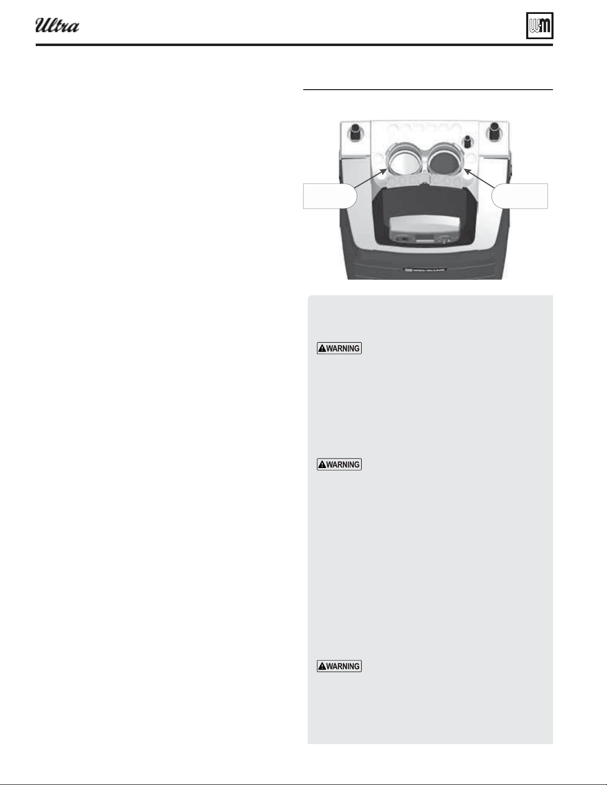
Part number 550-100-400/0119
82
®
Series 4
gas-fired water boiler — Boiler Manual
Install vent/air pipi ng — boiler to termination
Complete termination preparation
1. Install vent and air terminations before proceeding. See previ-
ous pages for instructions.
Installing vent and air piping
1. For reference in the following see:
a. Sidewall terminations: see Figure 105, page 92 .
b. Vertical terminations: see Figure 106, page 92 .
2. Work from the boiler to vent or air termination. Do not
exceed the lengths given in the previous pages for either the
air or vent piping.
a. As shown in the maximum length tables, the Ultra-80 or
Ultra-105 may be installed with either 2-inch or 3-inch
vent and air piping.
b. As shown in the maximum length tables, the Ultra-230
may be installed with either 3-inch or 4-inch vent and
air piping.
c. You must install appropriate pipe reducers, where re-
quired, at both the boiler and at the termination assembly.
3. See Figure 95 for attaching vent and air pipes at the boiler.
4. Cut pipe to required lengths.
5. Deburr inside and outside of pipe ends.
6. Chamfer outside of each pipe end to ensure even cement
distribution when joining.
7. Clean all pipe ends and fi ttings. Dry thoroughly.
8. Dry assemble entire vent or air piping to ensure proper fi t
before assembling any joint.
9. For each joint:
a. Handle fi ttings and pipes carefully to prevent contamina-
tion of surfaces.
b. Apply primer liberally to both joint surfaces — pipe end
and fi tting socket.
c. While primer is still damp, lightly apply approved cement
to both surfaces in a uniform coating.
d. Apply a second coat to both surfaces. Avoid using too
much cement on sockets to prevent cement buildup
inside.
e. With cement still wet, insert pipe into fi tting, twisting ¼
turn. Make sure pipe is fully inserted.
f. Wipe excess cement from joint. Check joint to be sure a
smooth bead of cement shows around the entire joint.
10. Install pipe supports as shown in Figure 105, page 92 or
Figure 106, page 92 .
11. Slope vent and air piping continuously toward boiler, with
at least 1/4 inch drop per foot of run. Do not allow sags at
any point.
12. Maintain minimum clearance of
3/16 inch between vent pipe
and any combustible wall or material.
13. Seal wall or fl oor penetration openings following local code
requirements.
Figure 95 Boiler ent and air connections
Inserting/securing vent or air pipe
into boiler connectors
AL29-4C vent pipe — If using AL29-4C stain-
less vent pipe, you must install a PVC-to-vent
pipe adapter at the boiler vent connection
(and at the termination if using the Weil-
McLain plate or the concentric termination).
Use only the adapter made by the vent pipe
manufacturer.
1. PVC/ABS pipe — Clean and chamfer insertion end of
pipe. Deburr inside of insertion end. Clean and deburr
inside and outside of other end of pipe.
The pipe end must be smooth and chamfered
to prevent possible damage to sealing gasket
in vent or air pipe adapter. Failure to comply
could result in leakage, causing possible severe
personal injury or death.
2. Inspect vent or air adapter (above) — verify no obstruc-
tions or foreign objects inside.
3. Loosen clamp screw.
4. Measure 3½ inches from end of pipe and make a mark
with felt-tip pen.
5. Loosen adapter clamp screw.
6. Apply small amount of silicon grease to end of pipe to
ease insertion.
7. Insert pipe into adapter.
8. Slide pipe down until the 3½-inch mark is reached.
Do not apply excessive force or bend the
adapter or fl ue/air pipe when inserting. The
adapter or seal could be damaged.
9. Secure vent or air pipe by tightening the adapter clamp
securely. Do not overtighten. The seal is accomplished
with the internal gasket. The clamp is only to hold the
pipe in place.
"JSQJQF
DPOOFDUPS
7FOUQJQF
DPOOFDUPS
6
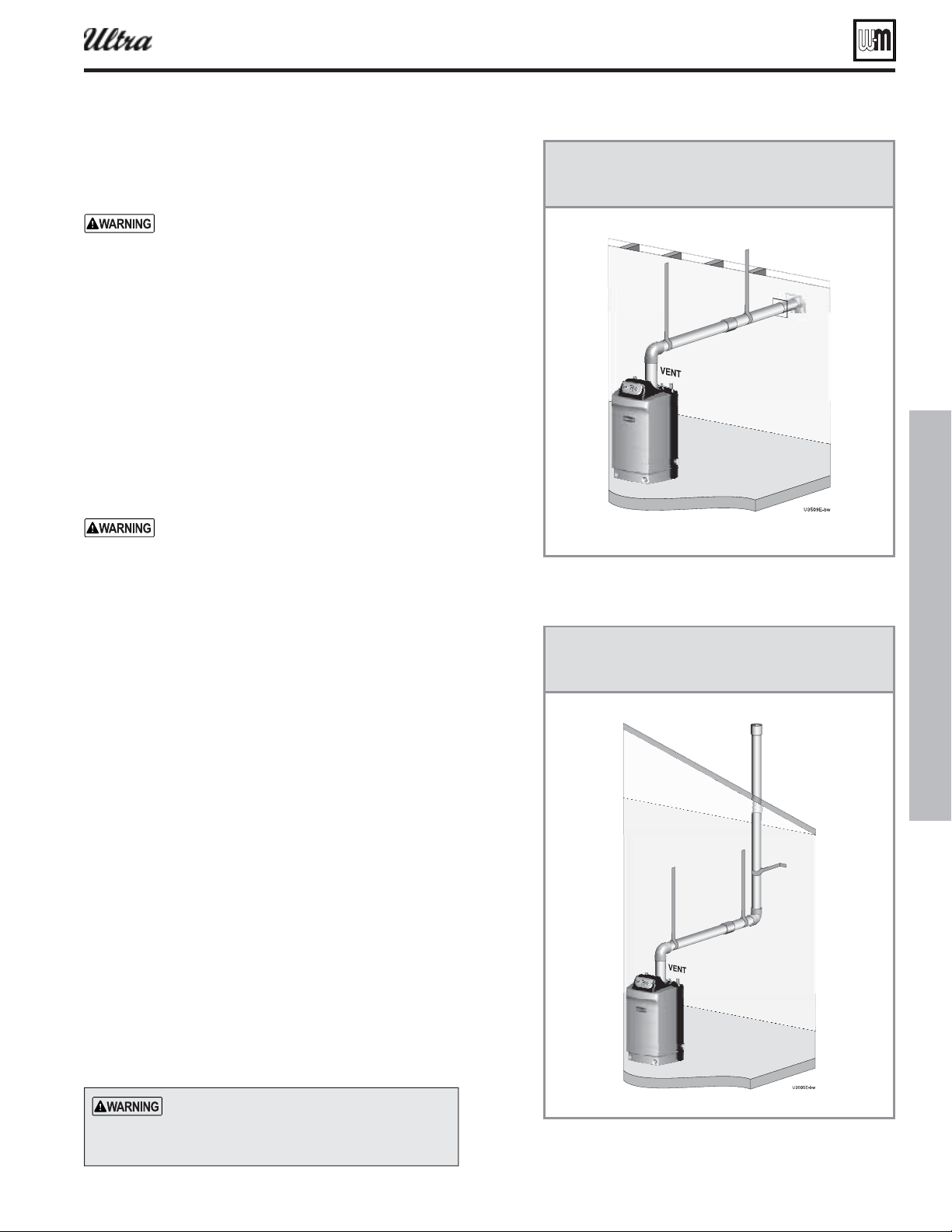
Part number 550-100-400/0119
83
®
Series 4
gas-fired water boiler — Boiler Manual
DIRECT EXHAUST venting — general
Vent and air piping materials
1. See Figure 13, page 19 for approved vent and air piping materi-
als, for both and .
— Do not connect different types of
piping together.
Vent piping
1. Boiler fl ue gases must be piped from the boiler to outside, fol-
lowing the instructions in this manual, and compliant with all
applicable codes. The vent pipe must terminate either through
the sidewall or through the roof, located with the correct sepa-
ration from the air termination. See the associated instructions
in the following pages.
2. Each Ultra boiler requires a separate vent. common
vent.
Combustion air openings for direct
exhaust
Combustion and ventilation
air for direct exhaust boilers is provided from the
boiler room. Follow all instructions in the Boiler
manual and this addendum plus all applicable codes,
providing combustion air openings as specifi ed.
Failure to comply could result in severe personal
injury, death or substantial property damage.
1. Combustion air must be supplied through openings into the
boiler room, following the instructions in this manual, and
compliant with all applicable codes. Read the warning on
page 16 , and ensure the air and boiler room will not contain
contaminated air.
2. Where the Ultra boiler shares a space with other appliances, the
combustion air openings must be sized to handle the combined
requirements of all appliances in the space.
SIDEWALL direct exhaust option
1. Read and follow instructions in Boiler manual, including
page 65 for Massachusetts installations when applicable.
VERTICAL direct exhaust option
1. Read and follow instructions in Boiler manual, including
page 65 for Massachusetts installations when applicable.
SIDEWALL
DIRECT EXHAUST
VERTICAL
DIRECT EXHAUST
Every vent pipe requires a
. Bird screens are not supplied
with the Ultra boiler. Purchase separately from
Weil-McLain.

Part number 550-100-400/0119
84
®
Series 4
gas-fired water boiler — Boiler Manual
Special considerations
Tight construction
ANSI Z223.1 defi nes unusually tight construction where:
1. Walls and ceilings exposed to the outside atmosphere have
a continuous water vapor retarder with a rating of 1 perm
or less with openings gasketed, and . . .
2. Weather-stripping has been added on openable windows
and doors, and . . .
3. Caulking or sealants are applied to areas such as joints
around windows and door frames, between sole plates and
fl oors, between wall-ceiling joints, between wall panels, at
penetrations for plumbing, electrical, and gas lines, and in
other openings.
For buildings with such construction, provide air openings
into the building from outside, sized per the appropriate case
in Figure 96, page 85 if appliances are to use inside air for com-
bustion and ventilation.
Exhaust fans and air movers
The appliance space must never be under a negative pressure
unless all appliances are installed as direct vent. Always provide
air openings sized not only to the dimensions required for the
fi ring rate of all appliances, but also to handle the air move-
ment rate of the exhaust fans or air movers using air from the
building or space.
Motorized air dampers
If the air openings are fi tted with motorized dampers, electrically
interlock the damper to:
Prevent the boiler from fi ring if the damper is not fully open.
Shut the boiler down should the damper close during boiler
operation.
To accomplish this interlock, wire an
isolated contact (proving
the damper open) in series with the thermostat input to the
boiler. The boiler will not start if this contact is open, and will
shut down should it open during operation.
Combustion air provision
The Ultra boiler can use inside air if no contaminants are pres-
ent in the boiler space. (If contaminants are likely to be present,
install the boiler as a direct vent appliance, using the appropriate
vent instructions in this manual.)
The boiler room must be fi tted with combustion air openings
large enough to provide air for all appliances in the room. Use the
following information to size the openings. Ensure the installation
complies with all applicable codes and standards.
Sizing combustion air openings
Air openings provide for ventilation (as well as combustion air)
to prevent overheating of the boiler controls and boiler space.
Air is also needed for other appliances located in the same space.
Use Figure 96, page 85 , selecting the appropriate installation
conditions.
Air openings must be sized to handle all appliances
and air movers (exhaust fans, etc.) using the air
supply.
The sizing given in Figure 96, page 85 is based on the National
Fuel Gas Code, ANSI Z223.1, allowing adequate air openings for
gravity-vented gas appliances (Category I) in addition to that
needed for the Ultra boiler.
The air openings recommended in Figure 96, page 85 will allow
adequate ventilation and combustion air provided the boiler
room is not subjected to negative pressure due to exhaust fans
or other mechanical ventilation devices.
Refer to the National Fuel Gas Code for dealing with other
conditions.
Free area — louver allowance
The free area of openings means the area after reduction for any
installed louvers or grilles
. Be sure to consider this reduction when
sizing the air openings.
DIRECT EXHAUS T — Boiler room air openings
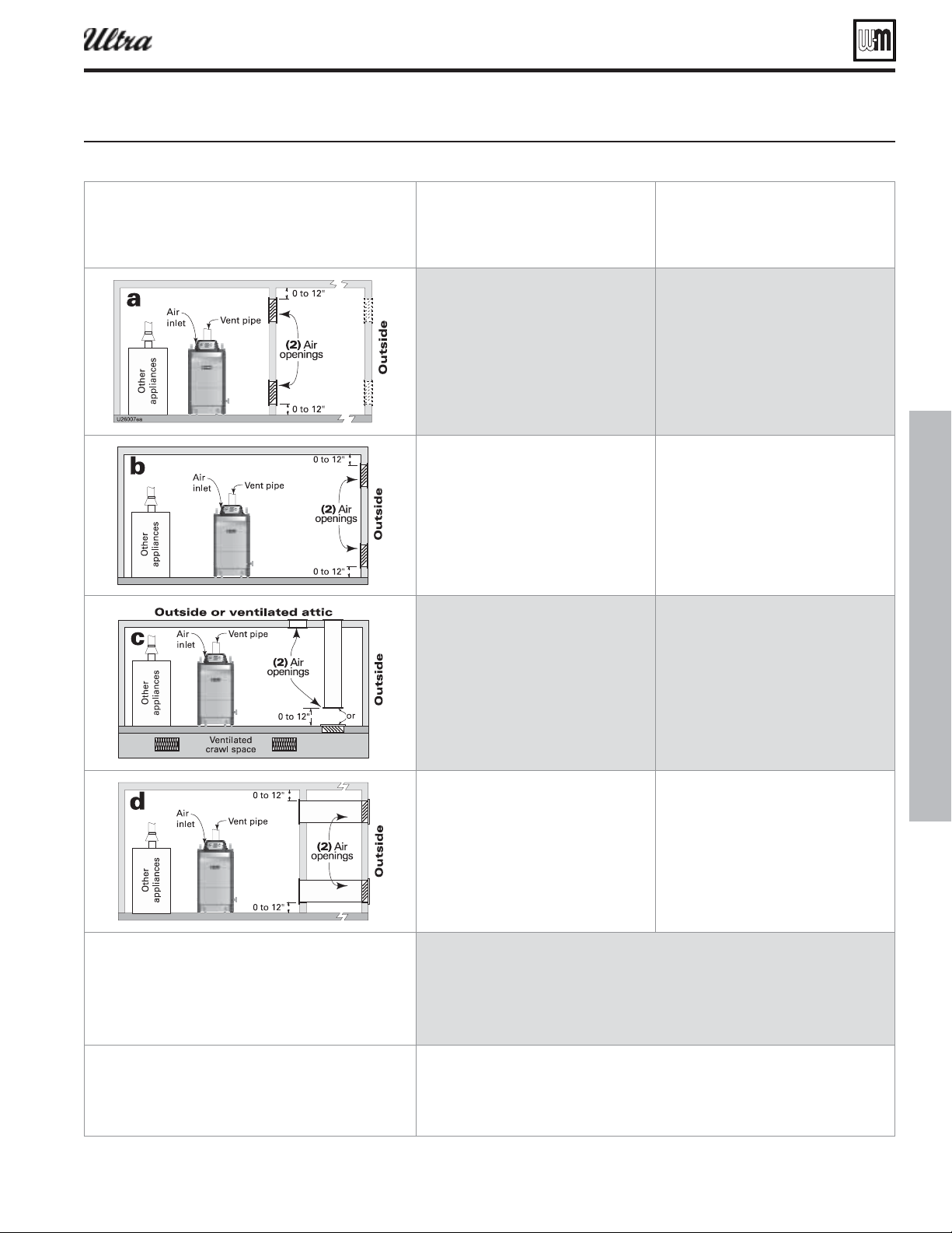
Part number 550-100-400/0119
85
®
Series 4
gas-fired water boiler — Boiler Manual
Figure 96 INIU comustion air openins for direct ehaust applications
Air openings
The required air opening sizes below are FREE AREA,
after reduction for louver obstruction. Note the ex-
ception below for large spaces.
Ultra boiler
WITH other
appliances in room
Ultra boiler
WITHOUT other
appliances in room
openings, each at least:
square inch per Btuh
of all appliances in the room
openings, each at least:
square inch per Btuh
of all appliances in the room
openings, each at least:
square inch per Btuh
of all appliances in the room
— OR —
opening **, each at least:
square inch per Btuh
of all appliances in the room
openings, each at least:
square inch per Btuh
of all appliances in the room
— OR —
opening **, each at least:
square inch per Btuh
of all appliances in the room
openings, each at least:
square inch per Btuh
of all appliances in the room
— OR —
opening **, each at least:
square inch per Btuh
of all appliances in the room
openings, each at least:
square inch per Btuh
of all appliances in the room
— OR —
opening **, each at least:
square inch per Btuh
of all appliances in the room
openings, each at least:
square inch per Btuh
of all appliances in the room
— OR —
opening **, each at least:
square inch per Btuh
of all appliances in the room
openings, each at least:
square inch per Btuh
of all appliances in the room
— OR —
opening **, each at least:
square inch per Btuh
of all appliances in the room
A single combustion air opening can be used for cases , or above, sized as listed,
provided that:
The single opening must communicate directly to the outdoors or to a space that
communicates directly with outdoors (NOT to an interior space).
The top of the opening must be within 12 inches of the ceiling.
The free area of the opening must be at least equal to the sum of the areas of all
equipment vent connectors in the space.
NO combustion air openings are needed when the boiler (and other appliances) are installed
in a space with a volume NO LESS than 50 cubic feet per 1,000 Btuh of all appliances in
the space. That is, total the input of all appliances in MBH (1,000’s of Btuh), then multiply
this total times 50. The building MUST NOT be of tight construction.
Example: For a total input of 1500 MBH (1,500,000 Btuh) and an 8-foot ceiling height,
the minimum volume would be 50 x 1500 x 8 = 60,000 cubic feet.
DIRECT EXHAUST —
Boiler room air openings
(continued)
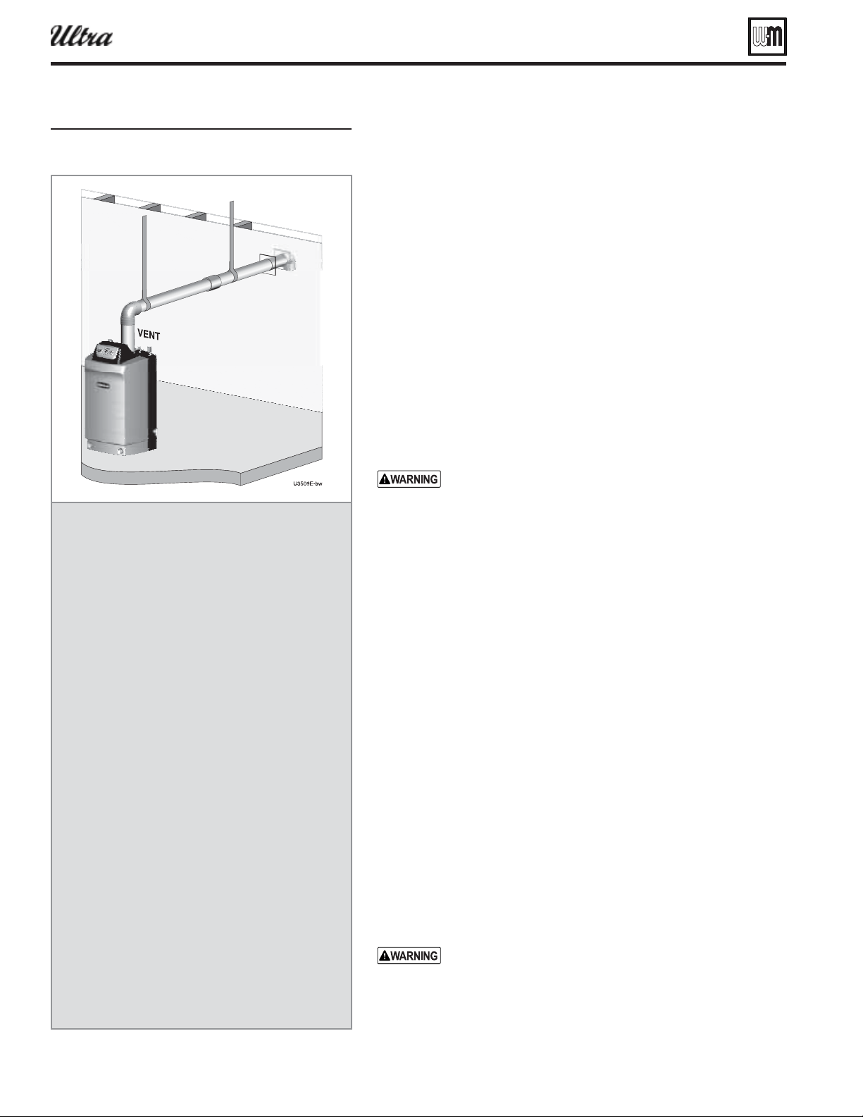
Part number 550-100-400/0119
86
®
Series 4
gas-fired water boiler — Boiler Manual
DIRECT EXHAUST — Sidewall
Figure 97
DIRECT EXHAUST — Sidewall
termination — installation
sequence overview
Step 1 Install the boiler.
Step 2 Determine the proper location for wall
penetration for each termination.
Prepare wall penetrations before installing
vent piping.
Finish by attaching external pipe and
fi ttings as shown in the termination in-
structions.
Support vertical runs on the outside of
the building with brackets as shown in the
termination instructions.
Step 3 Install vent piping from boiler to termi-
nation.
Install a hanger support within 6 inches of
any upturn in the piping.
Install pipe supports every 5 feet on both
the horizontal and vertical runs.
Slope horizontal piping downward toward
the boiler at least 1/4 inch per foot.
Step 4 Connect the vent piping at the boiler per
instructions in this addendum.
Allowable vent pipe materials
1. Use only the materials listed in Figure 13, page 19 .
2. Install a bird screen in each vent pipe termination (coupling or elbow).
Bird screens are not supplied with the Ultra boiler. Purchase separately
from Weil-McLain.
Maximum piping length
1. Locate the termination such that the total vent piping from the boiler
to the termination will not exceed the maximum length given in
Figure 12, page 18 .
2. Maximum lengths listed in Figure 12, page 18 allow for 2 elbows. Ad-
ditional elbows require a reduction in maximum length as explained
in the table notes.
Determine location for sidewall termination
A gas vent extending through an exterior wall shall not
terminate adjacent to the wall or below building extensions
such as eaves, parapets, balconies or decks, except as otherwise
instructed in this manual or local codes. Failure to comply
could result in severe personal injury, death or substantial
property damage.
Place the vent terminations using the following guidelines.
3. Terminate the vent piping with a down-turned elbow as shown in Fig-
ure 98, page 87 . The elbow must butt against the outside wall plate. If
vent piping is extended outside, install an elbow at the outer plate and
continue vent piping from the elbow when snorkeling as in Figure 98,
page 87 right side.
a. Apply the confi guration on the left side of Figure 98 unless the
termination would fail to meet minimum clearance to grade or
snow line.
b. Apply the confi guration on the right side of Figure 98 when the
termination needs to be raised higher to meet clearance to grade
or snow line.
c. The vent pipe may run up as high as 4 feet, as shown in Figure 98
right side, with no enclosure. The vent pipe must be secured with
braces, and maintain all required clearances.
d. Space braces no further than 24 inches apart. (See WARNING below
for extremely cold climates.)
e. External venting greater than 4 feet requires an enclosure around
the vent pipe. The vent termination must exit through the enclosure
as shown in Figure 98 , maintaining all required clearances.
Do not exceed the maximum length of the outside vent piping
shown in Figure 98 . Excessive length exposed to the outside
could cause freezing of condensate in the vent pipe, result-
ing in potential boiler shutdown. In extremely cold climates,
install an insulated chase around the vent piping, particularly
when using longer lengths. The chase must allow for inspec-
tion of the vent pipe, and insulation must be protected from
water.
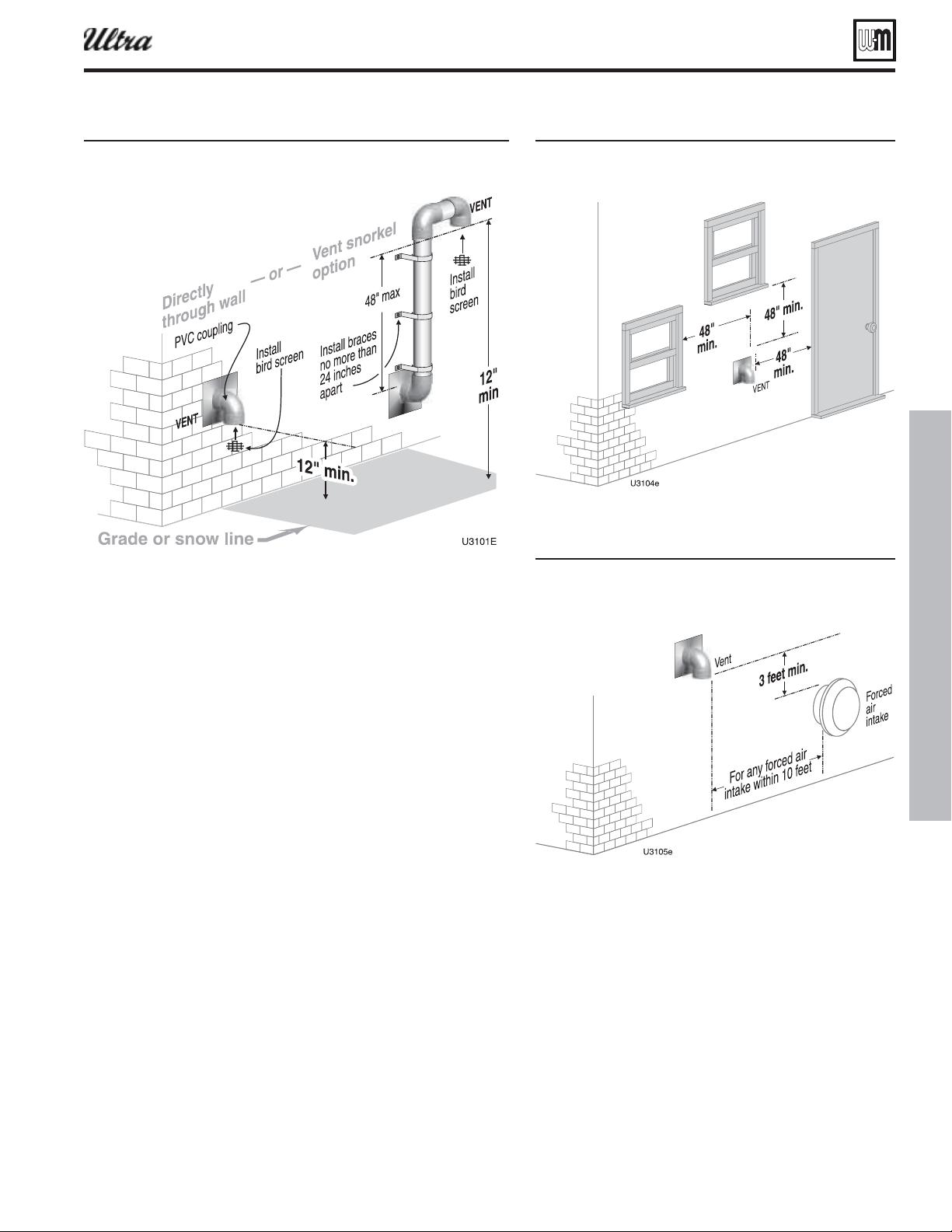
Part number 550-100-400/0119
87
®
Series 4
gas-fired water boiler — Boiler Manual
DIRECT EXHAUST — Sidewall (continued)
Figure 98 ICT AUST Sideall con uration options
and minimum clearances
4. Consider the surroundings when terminating the vent:
a. Position the vent termination where vapors will not damage
nearby shrubs, plants or air conditioning equipment or be
objectionable.
b. The fl ue products will form a noticeable plume as they con-
dense in cold air. Avoid areas where the plume could obstruct
window views.
c. Prevailing winds could cause freezing of condensate and water/
ice buildup where fl ue products impinge on building surfaces
or plants.
d. Avoid possibility of accidental contact of fl ue products with
people or pets.
e. Do not locate the terminations where wind eddies could affect
performance, such as inside building corners, near adjacent
buildings or surfaces, window wells, stairwells, alcoves, court-
yards or other recessed areas.
f. Do not terminate above any door or window or under a deck.
Condensate can freeze, causing ice formations.
g. Locate or guard vent to prevent condensate damage to exterior
fi nishes.
5. Maintain clearances as shown in the illustrations in this manual
section. Also maintain the following:
a. Vent must terminate:
At least 6 feet from adjacent walls.
No closer than 5 feet below roof overhang.
At lease 3 feet above any forced air intake within 10 feet.
No closer than 48 inches below or horizontally from any
door or window or any other gravity air inlet.
b. Do not terminate closer than 4 feet horizontally from any elec-
tric meter, gas meter, regulator, relief valve or other equipment.
Figure 99 ICT AUST Sideall
clearances to openins
Figure 100 ICT AUST Sideall
clearances from ent eit to forced air
intae
6. Because Ultra boilers are Category IV appliances, the
National Fuel Gas Code, ANSI Z223.1, requires that
the vent must not terminate over a public walkway or
over an area where condensate or vapor could create a
nuisance or hazard, or could be detrimental to the op-
eration of regulators, relief valves, or other equipment.
7. Where the vent penetrates an outside wall, the annular
space around the penetration must be permanently
sealed using approved materials to prevent entry of
combustion products into the building.
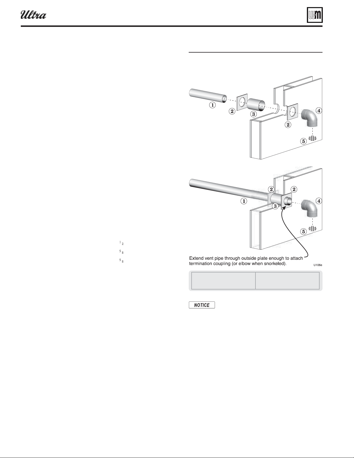
Part number 550-100-400/0119
88
®
Series 4
gas-fired water boiler — Boiler Manual
Figure 101 ICT AUST Sideall
termination asseml all parts
installer
1 Vent piping
2 Cover plates
3 Galvanized thimble
4 Vent termination elbow
5 Bird screen
DIRECT EXHAUST — Sidewall (continued)
The Weil-McLain sidewall termination kit
supplied with each boiler includes metal
plates with two openings. These plates can
be trimmed and used for direct exhaust vent
termination cover plates when the vent diam-
eter used matches the hole size in the plates
provided with the boiler.
8. Locate termination so it is not likely to be damaged by foreign
objects, such as stones or balls, or subject to buildup of leaves
or sediment.
9. Do not connect any other appliance to the vent pipe. Do not
connect multiple boilers to a common vent pipe.
Completing the vent piping
1. Install vent penetration as explained in the following before in-
stalling vent piping from the boiler to the termination.
2. Insert piping from boiler vent connections, then attach exterior
termination piping.
3. Follow instructions beginning on page 91 to complete piping
from boiler to termination.
Multiple vent terminations
1. When terminating multiple direct exhaust Ultra boilers, terminate
each vent connection as described in this manual for individual
vents. Space terminations as required for best installation prac-
tices and required maintenance.
Prepare wall penetrations
1. Wall penetration:
a. Cut a rough opening large enough to clear the diameter of
the metal thimble used.
b. Provide metal cover plates (item 2, Figure 101 ). The outer
plate MUST provide a stop to prevent the vent elbow from
being pushed inward. (See NOTICE at right.) Hole diameters
in the metal plates must be:
2-inch PVC, CPVC or ABS — 2
1
⁄2” hole diameter.
3-inch PVC, CPVC or ABS — 3
5
⁄8” hole diameter.
4-inch PVC, CPVC or ABS — 4
5
⁄8” hole diameter.
AL29-4C vent pipe and elbow — size hole large enough
to clear vent pipe, but small enough to prevent the elbow
from being pushed through.
c. Insert the galvanized metal thimble (by installer) in the vent
pipe hole as shown in Figure 101 .
2. Follow all local codes for isolation of vent pipe when passing
through fl oors or walls.
Termination and fi ttings
1. Prepare the vent termination elbow ( Figure 98, page 87 ) by in-
serting a bird screen. Bird screens are not supplied with the Ultra
boiler. Purchase separately from Weil-McLain.
2. You can install the vent termination using either of the confi gura-
tions shown in Figure 98, page 87 .
3. Maintain the required dimensions of the fi nished termination
piping as shown in Figure 98, page 87 .
4. Seal exterior openings thoroughly with exterior caulk.
5. Do not extend exposed vent pipe outside of the building more
than shown in this document. Condensate could freeze and block
vent pipe.
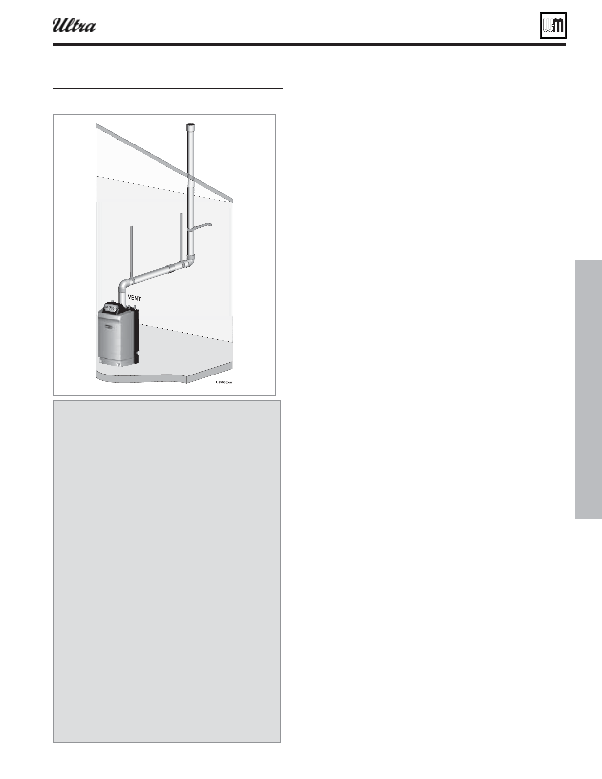
Part number 550-100-400/0119
89
®
Series 4
gas-fired water boiler — Boiler Manual
DIRECT EXHAUST — Vertical
Figure 102 ICT AUST ertical termination
Allowable vent pipe materials
1. Use only the materials listed in Figure 13, page 19 .
2. Install a bird screen in each vent pipe termination (coupling
or elbow). Bird screens are not supplied with the Ultra boiler.
Purchase separately from Weil-McLain.
Maximum piping length
1. Locate the termination such that the total vent piping from the boil-
er to the termination will not exceed the maximum length given in
Figure 12, page 18 .
2. Maximum lengths listed in Figure 12, page 18 allow for 2 elbows.
Additional elbows require a reduction in maximum length as
explained in the table notes.
Determine location for vertical termination
1. Locate the vent termination using the following guidelines:
2. The vent piping must terminate in a coupling as shown in Fig-
ure 103, page 90 .
3. Consider the surroundings when terminating the vent:
a. Position the vent termination where vapors will not damage
nearby shrubs, plants or air conditioning equipment or be
objectionable.
b. The fl ue products will form a noticeable plume as they
condense in cold air. Avoid areas where the plume could
obstruct window views.
c. Prevailing winds could cause freezing of condensate and
water/ice buildup where fl ue products impinge on building
surfaces or plants.
d. Avoid possibility of accidental contact of fl ue products with
people or pets.
e. Do not locate the termination where wind eddies could affect
performance or cause recirculation, such as inside building
corners, near adjacent buildings or surfaces, window wells,
stairwells, alcoves, courtyards or other recessed areas.
f. Locate or guard vent to prevent condensate damage to ex-
terior fi nishes.
4. Maintain clearances as shown in the illustrations in this manual
section. Also maintain the following:
a. Vent must terminate:
At least 12 inches above roof or snow line as shown in
Figure 103 .
At least 6 feet from adjacent walls.
No closer than 5 feet below roof overhang.
At lease 3 feet above any forced air intake within 10 feet.
No closer than 48 inches below or horizontally from any
door or window or any other gravity air inlet.
b. Do not terminate closer than 4 feet horizontally from any
electric meter, gas meter, regulator, relief valve or other
equipment.
5. Where the vent penetrates the roof, the annular space around the
penetration must be permanently sealed using approved materi-
als to prevent entry of combustion products into the building.
6. Locate terminations so they are not likely to be damaged by
foreign objects, such as stones or balls, or subject to buildup of
leaves or sediment.
7. Do not connect any other appliance to the vent pipe. Do not
connect multiple boilers to a common vent pipe.
DIRECT EXHAUST — Vertical
termination — installation
sequence overview
Step 1 Install the boiler.
Step 2 Determine the proper location for wall pen-
etration for each termination.
Prepare roof penetrations before installing vent
piping.
Finish by attaching external pipe and fi ttings as
shown in the termination instructions.
Install terminations as described in this manual.
Support vertical runs on the outside of the
building with brackets as shown in the termina-
tion instructions.
Step 3 Install vent piping from boiler to termination.
Install a hanger support within 6 inches of any
upturn in the piping.
Install pipe supports every 5 feet on both the
horizontal and vertical runs.
Slope horizontal piping downward toward the
boiler at least 1/4 inch per foot.
Step 4 Connect the vent piping at the boiler per
manual instructions.
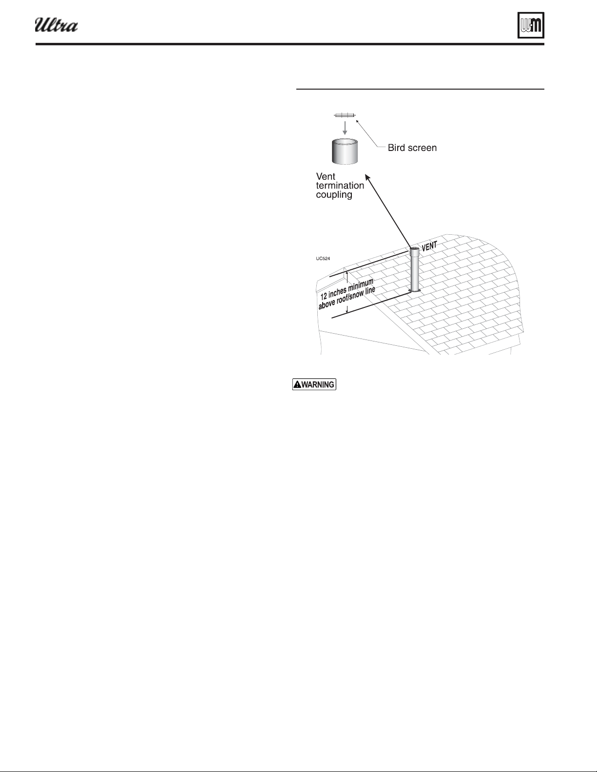
Part number 550-100-400/0119
90
®
Series 4
gas-fired water boiler — Boiler Manual
DIRECT EXHAUST — Vertical (continued)
Figure 103 ICT AUST ertical termination
Prepare roof penetration
1. Vent pipe penetration:
a. Cut a hole for the vent pipe. For either combustible
or noncombustible construction, size the vent pipe
hole at least 0.5” larger than the vent pipe diameter:
3” hole for 2”
4” hole for 3”
5” hole for 4”
b. Insert a galvanized metal thimble in the vent pipe
hole.
2. Follow all local codes for isolation of vent pipe when
passing through fl oors, ceilings and roofs.
3. Provide fl ashing and sealing boots sized for the vent
pipe and air pipe.
Termination and fi ttings
1. Prepare the vent termination coupling ( Figure 103 ) by
inserting a bird screen. Bird screens are not supplied with
the Ultra boiler. Purchase separately from Weil-McLain.
2. The vent piping must terminate in a coupling as shown
in Figure 103 .
3. Maintain the required dimensions of the fi nished ter-
mination piping as shown in Figure 103 .
4. Do not extend exposed vent pipe outside of building
more than shown in this document. Condensate could
freeze and block vent pipe.
Multiple vent terminations
1. When terminating multiple Ultra boilers, terminate
each vent connection as described in this section. Space
terminations as required for best installation practices
and required maintenance.
Complete termination preparation
2. Install vent terminations before proceeding. See previous
pages for instructions.
Installing direct exhaust vent piping
1. For reference in the following see:
a. Sidewall terminations: see Figure 97, page 86 .
b. Vertical terminations: see Figure 102, page 89 .
2. Work from the boiler to vent or air termination. Do not
exceed the lengths given in the previous pages for either
the air or vent piping.
a. As shown in the maximum length tables, the
Ultra-80 or Ultra-105 may be installed with either
2-inch or 3-inch vent piping.
b. As shown in the maximum length tables, the
Ultra-230 may be installed with either 3-inch or
4-inch vent piping.
c. You must install appropriate pipe reducers, where
required, at the boiler vent connection.
3. See Figure 104 for attaching vent and air pipes at the
boiler.
4. Cut pipe to required lengths.
: The vent pipe must extend
through the outer cover plate only enough to install
the termination elbow. The plate must provide a stop
to prevent the vent elbow from being pushed inward.
5. Deburr inside and outside of pipe ends.
6. Chamfer outside of each pipe end to ensure even cement dis-
tribution when joining.
7. Clean all pipe ends and fi ttings. Dry thoroughly.
8. Dry assemble entire vent or air piping to ensure proper fi t
before assembling any joint.
9. For each joint:
a. Handle fi ttings and pipes carefully to prevent contamina-
tion of surfaces.
b. Apply primer liberally to both joint surfaces — pipe end
and fi tting socket.
c. While primer is still damp, lightly apply approved cement
to both surfaces in a uniform coating.
d. Apply a second coat to both surfaces. Avoid using too much
cement on sockets to prevent cement buildup inside.
e. With cement still wet, insert pipe into fi tting, twisting ¼
turn. Make sure pipe is fully inserted.
f. Wipe excess cement from joint. Check joint to be sure a
smooth bead of cement shows around the entire joint.
10. Install pipe supports as shown in Figure 105, page 92 or
Figure 106, page 92 .
11. Slope vent and air piping continuously toward boiler, with at
least 1/4 inch drop per foot of run. Do not allow sags at any
point.
12. Maintain minimum clearance of
3/16 inch between vent pipe
and any combustible wall or material.
13. Seal wall or fl oor penetration openings following local code
requirements.
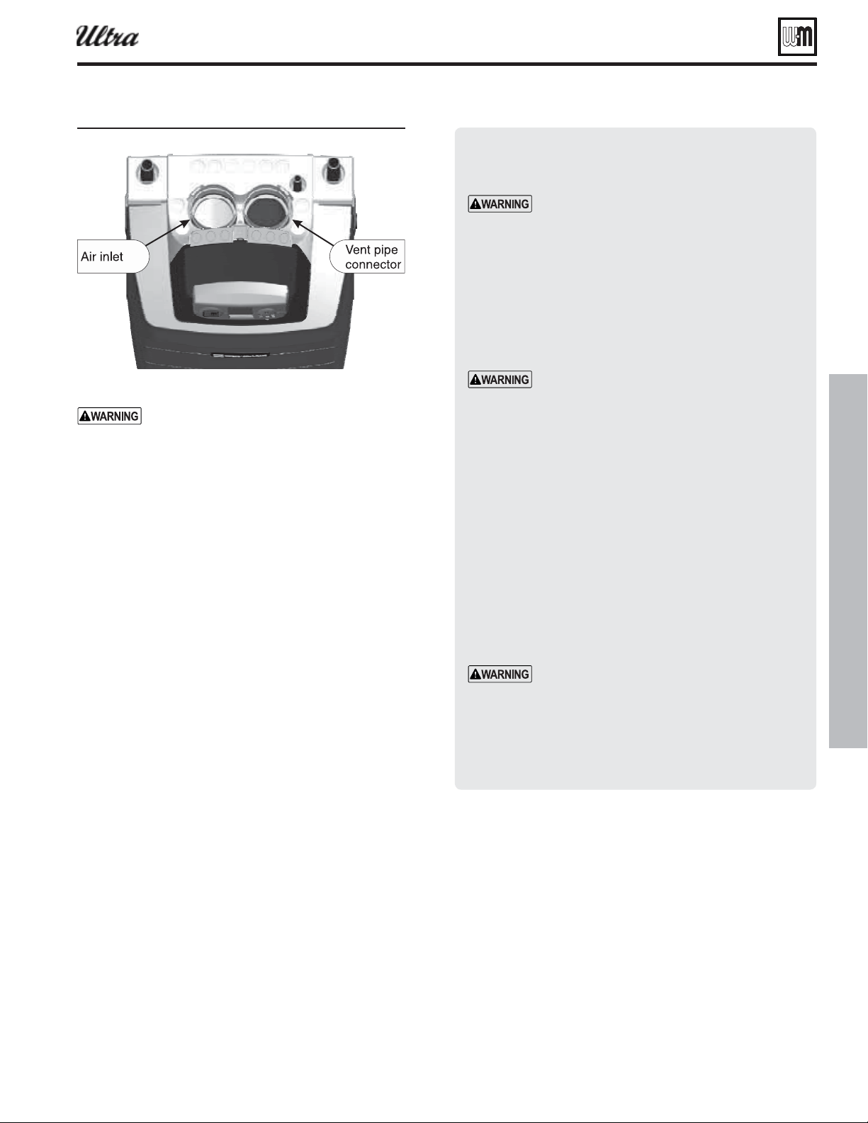
Part number 550-100-400/0119
91
®
Series 4
gas-fired water boiler — Boiler Manual
Figure 104 Boiler ent and air connections
Inserting/securing vent or air pipe
into boiler connectors
AL29-4C vent pipe — If using AL29-4C stain-
less vent pipe, you must install a PVC-to-vent
pipe adapter at the boiler vent connection (and
at the termination if using the Weil-McLain
plate or the concentric termination). Use only
the adapter made by the vent pipe manufac-
turer.
1. PVC/ABS pipe — Clean and chamfer insertion end of
pipe. Deburr inside of insertion end. Clean and deburr
inside and outside of other end of pipe.
The pipe end must be smooth and chamfered
to prevent possible damage to sealing gasket
in vent or air pipe adapter. Failure to comply
could result in leakage, causing possible severe
personal injury or death.
2. Inspect vent or air adapter (above) — verify no obstruc-
tions or foreign objects inside.
3. Loosen clamp screw.
4. Measure 3½ inches from end of pipe and make a mark
with felt-tip pen.
5. Loosen adapter clamp screw.
6. Apply small amount of silicon grease to end of pipe to
ease insertion.
7. Insert pipe into adapter.
8. Slide pipe down until the 3½-inch mark is reached.
Do not apply excessive force or bend the adapter
or fl ue/air pipe when inserting. The adapter or
seal could be damaged.
9. Secure vent or air pipe by tightening the adapter clamp
securely. Do not overtighten. The seal is accomplished
with the internal gasket. The clamp is only to hold the
pipe in place.
: Obtain a bird
screen (sized for air inlet opening) the from
Weil-McLain. Insert the bird screen into the
air inlet opening to prevent foreign objects
from falling into the opening.
Install vent — from boiler to termination
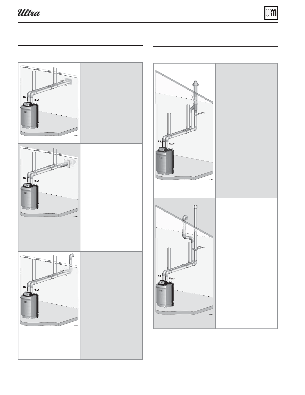
Part number 550-100-400/0119
92
Install vent/air piping — boiler to terminations (cont.)
Figure 105
install termination pae
Install pipe supports every 5 feet
on both the horizontal and vertical
runs.
Install a hanger support within
6 inches of any upturn in the
piping.
The Weil-McLain plate
termination must be installed
before piping from the boiler to
the termination.
Slope horizontal piping downward
toward the boiler at least 1/4 inch
per foot.
install termination pae
Install pipe supports every 5 feet
on both the horizontal and vertical
runs.
Install a hanger support within
6 inches of any upturn in the
piping.
The Weil-McLain 3” PVC
concentric termination assembly
must be installed before piping
from the boiler to the termination.
Support the termination at the
wall as shown in the termination
instructions.
Slope horizontal piping downward
toward the boiler at least 1/4 inch
per foot.
Rotate the concentric termination
Y-fi tting about 30° to result in pipe
centers the same as at the boiler.
install termination pae
Prepare wall penetrations before
installing vent and air piping.
Finish by attaching external
pipe and fi ttings as shown in the
termination instructions.
Install pipe supports every 5 feet
on both the horizontal and vertical
runs.
Install a hanger support within
6 inches of any upturn in the
piping.
Support vertical runs on the
outside of the building with
brackets as shown in the
termination instructions.
Slope horizontal piping downward
toward the boiler at least 1/4 inch
per foot.
Figure 106
install termination pae
Install pipe supports every 5 feet
on both the horizontal and vertical
runs.
Install a hanger support within
6 inches of any upturn in the
piping.
The Weil-McLain 3” PVC
concentric termination assembly
must be installed before piping
from the boiler to the termination.
Support the termination at
the ceiling and above the roof
as shown in the termination
instructions.
Slope horizontal piping downward
toward the boiler at least 1/4 inch
per foot.
Use long-radius elbows for air
piping when using 2” or 3” pipe to
reduce pressure drop.
Rotate the concentric termination
Y-fi tting about 30° to result in pipe
centers the same as at the boiler.
install termination pae
Prepare roof penetrations before
installing vent and air piping.
Finish by attaching termination
fi ttings as shown in termination
instructions.
Install pipe supports every 5 feet
on both the horizontal and vertical
runs.
Install a hanger support within
6 inches of any upturn in the
piping.
Slope horizontal piping downward
toward the boiler at least 1/4 inch
per foot.
Air piping may be offset as
shown at left so termination
can be located as required in the
installation instructions.
Use long-radius elbows for air
piping when using 2” or 3” pipe to
reduce pressure drop.
®
Series 4
gas-fired water boiler — Boiler Manual
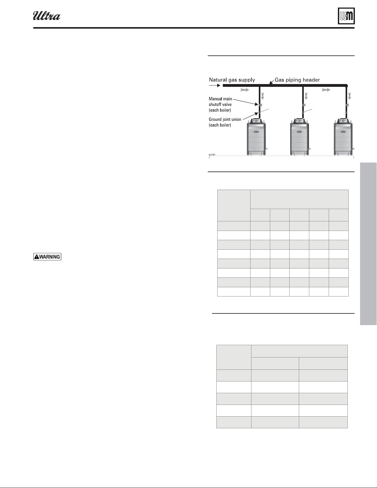
Part number 550-100-400/0119
93
Gas piping — sizing gas lines
Natural Gas:
Pipe sizing for natural gas
1. Size gas piping from meter outlet to entrance of boiler in accor-
dance with Figure 108 and Figure 109 .
2. Use total input of all boilers. Divide total input in Btuh by 1,000
to obtain cubic feet per hour of natural gas.
a. Pipe lengths in Figure 108 are equivalent length of straight
pipe. Convert pipe fi ttings to equivalent lengths using data
from Figure 107 .
b. Figure 108 is only for natural gas with specifi c gravity 0.60, with
a pressure drop through the gas piping of 0.30” w.c.
c. For additional gas pipe sizing information, refer to ANSI
Z223.1 NFPA 54 (or Natural Gas and Propane Installation
CAN/CSA
B149.1 or B149.2 for Canadian installations).
Natural gas supply pressure
1. Pressure required at gas valve inlet pressure port:
a. Maximum: 13” w.c. with no fl ow (lockup) or with boiler on
b. Minimum: 4” w.c. (for all except 5” for -299/310) with gas
fl owing (verify during boiler startup, while boiler is at high fi re)
2. Install 100% lockup gas pressure regulator in supply line if inlet
pressure can exceed 13” w.c. at any time. Adjust lockup regulator
for 13” w.c. maximum.
Propane Gas:
You must follow the instructions, beginning on page 48 ,
to operate the boiler on propane. Failure to comply could
result in severe personal injury, death or substantial
property damage.
Pipe sizing for propane gas
1. Contact gas supplier to size pipes, tanks and 100% lockup gas
pressure regulator.
Propane supply pressure
1. Adjust propane supply regulator provided by gas supplier for 13”
w.c. maximum pressure.
2. Pressure required at gas valve inlet pressure port:
a. Maximum: 13” w.c. with no fl ow (lockup) or with boiler on
Minimum: 4” w.c. with gas fl owing (verify during boiler
startup, while boiler is at high fi re).
Manifolded gas supply lines
1. Construct gas header for multiple boilers using Figure 107 and
the sizing tables below. Refer to the National Fuel Gas Code for
other conditions.
2. Provide manual shutoff gas valve and ground joint union as shown
in Figure 33, page 29 and Figure 107 for each boiler. When gas
line enters from top of the boiler, the boiler internal gas piping
provides a drip leg.
3. A ¾” NPT gas piping riser from header to boiler will be large
enough for most jobs. Ensure the piping is large enough so that
the minimum pressure at the boiler will be at least 5 inches water
column with all connected appliances fi ring.
®
Series 4
gas-fired water boiler — Boiler Manual
inches
2.62 5.24
3.45 6.90
4.02 8.04
5.17 10.3
6.16 12.3
Figure 107 Common as line for multiple oilers
cuic feet per hour . speci c rait
520 1050 1600 3050 4800
350 730 1100 2100 3300
285 590 890 1650 2700
245 500 760 1450 2300
215 440 670 1270 2000
175 360 545 1020 1650
150 305 460 870 1400
120 250 380 710 1130
Figure 108 ipe capacit for . speci c rait natural
as
Figure 109 uialent lenths of straiht pipe for
tpical as line ttins
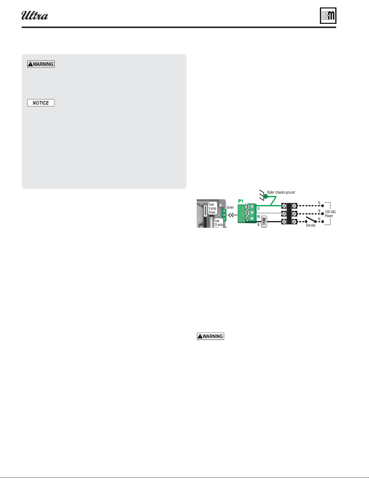
Part number 550-100-400/0119
94
Field wiring — advanced
secondary heat source when another heat source,
such as a heat pump or another boiler is available.
❏
❏
The U-Control provides the fl exibility for control
of multiple Ultra boilers.
You will need to program the boilers’ U-Controls
based on the interconnection method you choose.
❏
The boiler is shipped with an outdoor sensor, a
system supply sensor and a system return sensor.
The system supply sensor will be required for most
space heating applications. The system return sensor
must also be installed when using the system supply
sensor. Use of the outdoor sensor is optional.
Line voltage power input
1. Provide and install a fused disconnect or service switch
(15-ampere rated recommended) as required by ap-
plicable codes.
2. Connect minimum 15-ampere, 120 VAC power wiring
to Ultra boiler line voltage terminal strip as shown in
Figure 111, page 96 and above.
Wiring circulators
1. The U-Control provides for connection of up to three
circulators, one of which must be the boiler circulator.
In addition, you can connect a system circulator and a
DHW circulator, for examples. See Figure 110, page 95 .
. For
circulators with higher amp ratings, you must
install a circulator relay or starter to provide
line voltage to the circulator. For circulators
rated over 2.2 amps, connect only the circula-
tor relay or starter coil to the Ultra circulator
terminals.
2. You can connect any of the circulators you use to any of
the three circulator activation terminals. The U-Control
setup allows you to assign which circulators activate on
a call for heat (this can be customized for each of the
heating systems supplied by the boiler).
3. The U-Control factory
settings for DHW heat-
ing are confi gured for direct piping to the boiler, with
Circulator 1 being the only circulator being activated
Wiring — general
1. The U-Control provides plug-in, color-coded, non-interchange-
able terminal strips for all fi eld wiring. See the schematic diagram
( Figure 111, page 96Figure 112, page 97 ).
2. The U-Control provides programmable fl exibility in system op-
eration, allowing control of heat supply for up to three different
heating systems. Read this manual thoroughly before connecting
the wiring to ensure trouble-free start-up and operation.
Wiring — overview
You will need to make the following connections, some of which
depend on your system and how the U-Control will be programmed.
(
See this and following pages for more information.)
❏
❏
❏
Two different circuits are available — The U-Control will
require manual reset for one of these circuits. The U-Control
will automatically reset after limit operation and re-closure
for limits in the other circuit.
❏
The U-Control can regulate the boiler for up to three different
heating systems.
❏
The U-Control will operate and modulate the boiler based
on a 0–10 VDC control signal from a remote controller, when
desired.
❏
The U-Control allows the boiler to act as the primary or
— For your
safety, turn off electrical power supply at service
entrance panel before making any electrical connec-
tions to avoid possible electric shock hazard. Failure
to do so can cause severe personal injury or death.
Wiring must be N.E.C. Class 1. If original wiring as
supplied with boiler must be replaced, use only type
105 °C wire or equivalent. Boiler must be electrically
grounded as required by National Electrical Code
ANSI/NFPA 70 – latest edition.
Installation must comply with:
1. National Electrical Code and any other national, state, provincial or
local codes or regulations.
2. In Canada, CSA C22.1 Canadian Electrical Code Part 1, and any local
codes.
®
Series 4
gas-fired water boiler — Boiler Manual
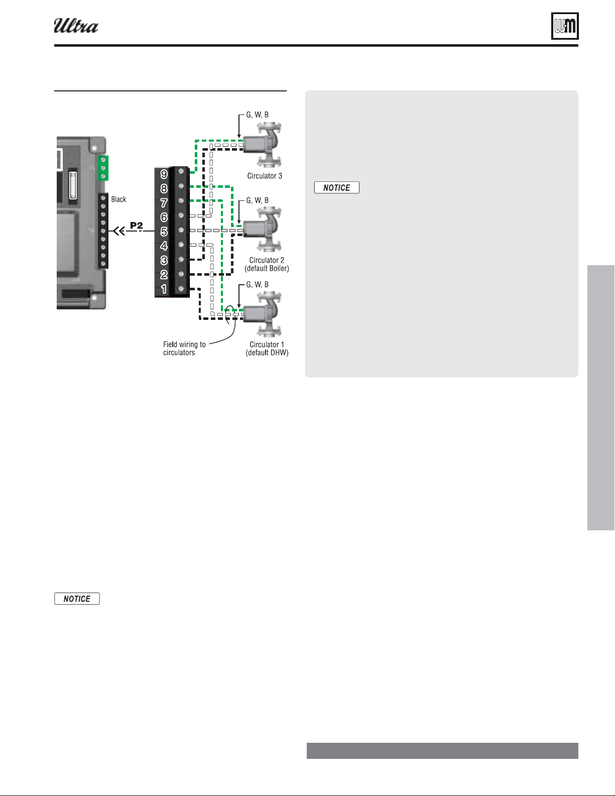
Part number 550-100-400/0119
95
Field wiring — advanced (continued)
during DHW heating. To use factory default settings,
make sure to connect the DHW circulator to terminals 1,
4 and 7, as below:
4. The factory
for space heating is designed for
fi nned-tube baseboard, and set up to activate Circula-
tor 2 and Circulator 3 on a call for heat. Connect the
boiler circulator to terminals 2, 5 and 8 and the system
circulator to terminals 3, 6 and 9 to use these default
settings.
5. Make sure the U-Control is programmed to activate
the system circulator when it is required (during space
heating, for instance).
Thermostats & DHW tank
temperature control connections
Use isolating relays if using 3-wire zone valves
to avoid damage and nuisance problems due
to stray voltage.
1. The U-Control allows operation by up to three different
heating systems.
2. The factory default confi guration is for “heat demand 1”
to be DHW and “heat demand 2” to be space heating.
For factory default operation:
a. Connect the space heating thermostat to terminal
strip P15, terminals 1 and 2 to use the default setup.
b. Connect the DHW tank temperature control across
terminal strip P11, terminals 4 and 5 to use the
default setup.
3. Install thermostats on inside walls away from the infl uences of
drafts, hot or cold water pipes, lighting fi xtures, television, sun
rays, or fi replaces.
4. Thermostat anticipator (if applicable):
If connected directly to the boiler, set anticipator for 0.1 amps.
If connected to relays or other devices, set to match total elec-
trical power requirements of connected devices. See device
manufacturers’ specifi cations and the thermostat instructions
for details.
Low water cut-offs
1. See the on this page regarding internal low water protec-
tion provided by the U-Control.
2. When an external low water cut-off is installed, connect as shown
in the U-Control wiring diagrams ( Figure 111, page 96Fig-
ure 112, page 97 ).
3. When possible, use the Weil-McLain Ultra low water cut-off kit
listed in the back of this manual. It includes a probe-type low water
cut-off and provides a simple harness connection for the wiring.
The U-Control m odule provides internal
low water protection
1. The U-Control and internal sensors in the Ultra boiler provide
both temperature control and low water protection (using
temperature senors), as explained below:
The U-Control module uses temperature sensors to
provide both high limit protection and modulating
temperature control.
The U-Control module also provides
by using a dual sensor to monitor the
temperature of the heat exchanger. [The U-Control
constantly monitors the sensor signals to ensure
they are within 10 °F of one another. If the sensor
difference exceeds 10 °F, the boiler is shutdown on
automatic reset.] This method is accepted in many
areas as meeting the requirement for a low water
cut-off.
Some codes or jurisdictions may require additional
external controls for high limit and/or low water
cutoff protection. Follow the guidelines in this
manual to install additional controls when required.
Figure 110 irin to circulators
®
Series 4
gas-fired water boiler — Boiler Manual
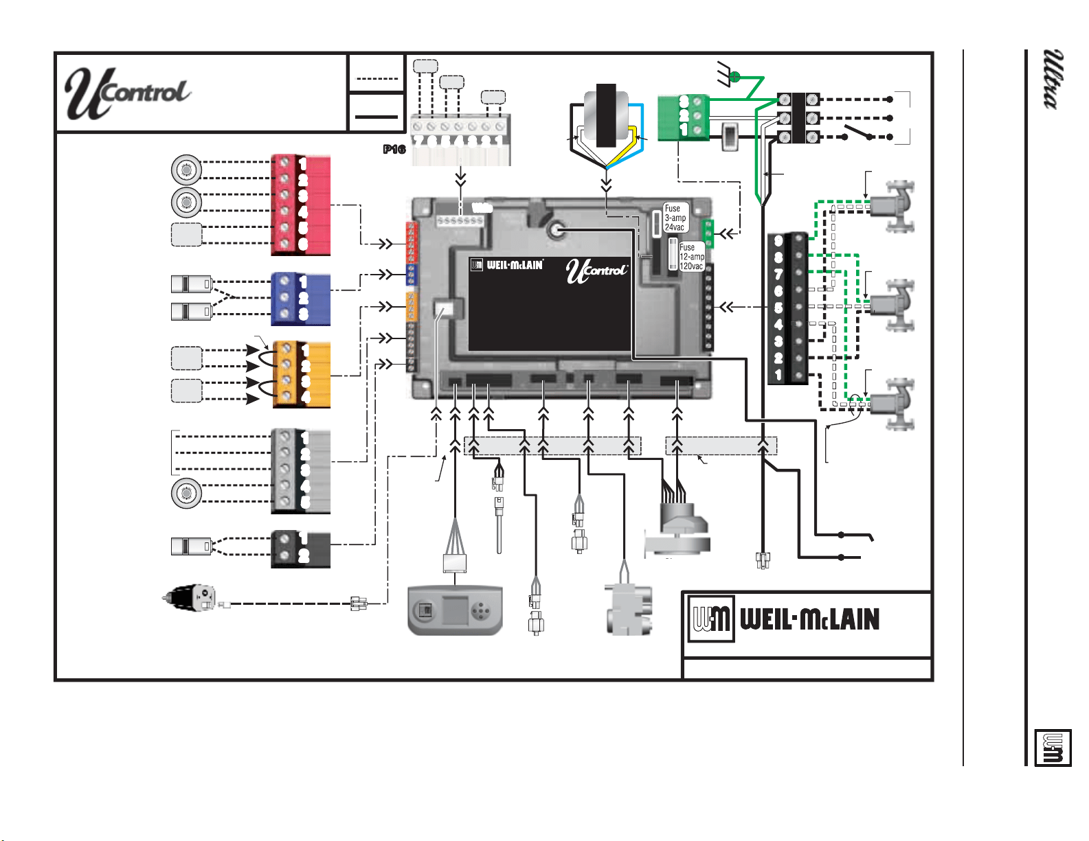
Part number 550-100-400/0119
96
Field wiring — advanced (continued)
Figure 111Schematic irin diaram Ultra- throuh Ultra-
8FJM.D-BJOt#MBJOF4Ut.JDIJHBO$JUZ*/
1BSU/VNCFS
@
7
4DIFNBUJD
8JSJOH%JBHSBN
4FFMBEEFSXJSJOHEJBHSBNGPSOPUFT
$BMMGPSIFBUEFNBOE
%FGBVMUGPSUIFSNPTUBU
4FF54/05&CFMPX
$BMMGPSIFBUEFNBOE
4FF54/05&CFMPX
.PEVMBUJOHJOQVU
o7%$
4ZTUFNTVQQMZ
UFNQFSBUVSFTFOTPS
"EEJUJPOBMMJNJUTJGVTFE
8JMMSFRVJSFNBOVBMSFTFU
"EEJUJPOBMMJNJUTJGVTFE
$POUSPMXJMMBVUPNBUJDBMMZ
SFTFU
$BMMGPSIFBUEFNBOE
%FGBVMU%)8JOQVU
4FF54/05&CFMPX
0VUEPPSUFNQTFOTPS
JGVTFE
-PXXBUFSDVUPGGJGVTFE
4FF/PUF
1
1
1
1
1
1
%JTQMBZJOUFSGBDF
QBOFM
'MVFUFNQ
TFOTPS
)FBUFYDIBOHFS
PVUMFUUFNQ
TFOTPS
)FBUFYDIBOHFS
JOMFUUFNQ
TFOTPS
(BT
WBMWF
#MPXFS
3FE
#MVF
0SBOHF
(SBZ
#MBDL
(SFFO
8IJUF
"EEJUJPOBMIFBUEFNBOEDPOUBDUT
QJO
DPOOFDUPS
UISPVHI
DBCJOFU
7"$
1PXFS
#PJMFSDIBTTJTHSPVOE
(
/
)
4FSWJDF
TXJUDI
0/0''
TXJUDI
5FTUQPXFS
$JSDVMBUPS
$JSDVMBUPS
%FGBVMU#PJMFS
$JSDVMBUPS
%FGBVMU%)8
#MBDL
1
*HOJUJPO
FMFDUSPEF
(SPVOE
(
8
#
8
#(
/05&$POOFDUXJSF
IBSOFTTFTUPDJSDVMBUPST
JOUIFGJFME
1
1
$PNNPO
'JFMEXJSJOH
'BDUPSZXJSJOH
QJO
DPOOFDUPS
UISPVHI
DBCJOFU
(8#
5SBOTGPSNFS
1
7
#,
8)
:
#-
'BDUPSZKVNQFSTSFNPWFJGVTJOHMJNJUT
4ZTUFNSFUVSO
UFNQFSBUVSFTFOTPS
$PN
(8#
(8#
"MBSNDPOUBDUT
54/05&
r%0/05TVQQMZWPMUQPXFSUPUIFUIFSNPTUBUDJSDVJUT*G
VTJOHXJSF[POFWBMWFTVTFSFMBZTUPQSPWJEFESZDPOUBDUTUPUIF
6MUSB$POUSPM.PEVMFUIFSNPTUBUDPOOFDUJPOT
.PEVMBUJOH
PVUQVU
o7%$
@
'VUVSFVTF
7$PNNPO
®
Series 4
gas-fired water boiler — Boiler Manual
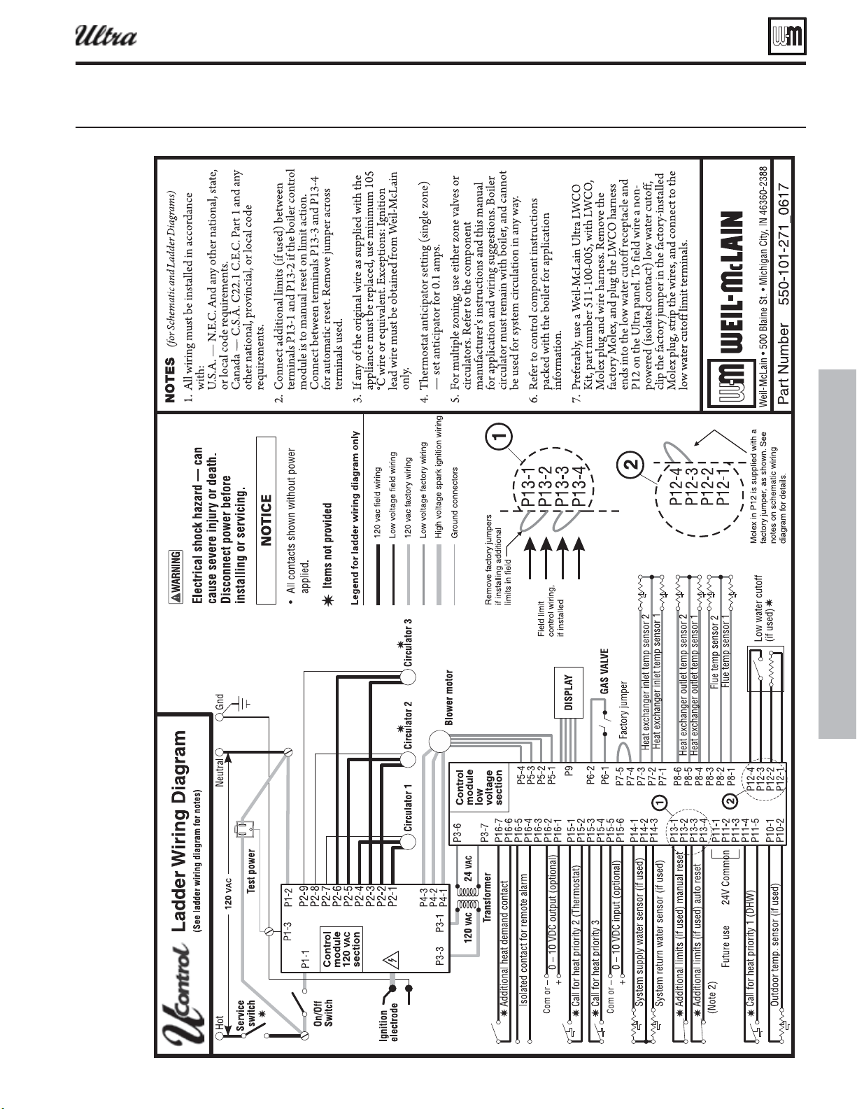
Part number 550-100-400/0119
97
Figure 112Ladder irin diaram Ultra- throuh Ultra-
Field wiring — advanced (continued)
®
Series 4
gas-fired water boiler — Boiler Manual
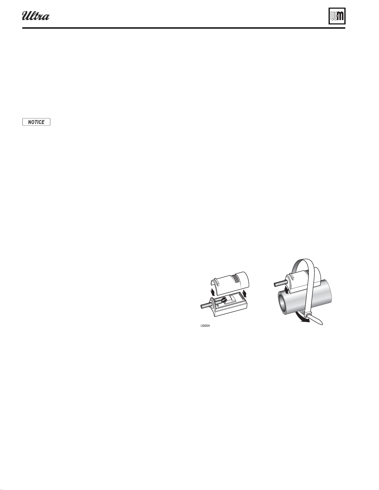
Part number 550-100-400/0119
98
Field wiring — advanced (continued)
Add itional limits
1. The U-Control allows connection of external limit controls,
both for manual reset and for automatic reset operation of the
U-Control.
— Connect
external limits across P13, terminals 1 and 2 if the U-Control is
to require manual reset when a limit opens, even if the limit re-
closes. (Remove the factory jumper when using these terminals.)
The U-Control will lockout when a limit in its manual
reset circuit opens. The U-Control activates its alarm
terminals and shuts the boiler down until an operator
manually resets the U-Control (as explained in this
manual). This reset function can be done by a home-
owner or a service technician.
— Connect
external limits across P13, terminals 3 and 4 if the U-Control is to
reset automatically when the limit circuit closes after a limit con-
dition. (Remove the factory jumper when using these terminals.)
Remote operation/modulation
1. The U-Control module provides terminals to input a remote
0–10 VDC operating signal. This can be provided by a separate
controller if the boiler is confi gured as Type 4 (SHADOW boiler
mode).
2. Connect the 0–10 VDC signal positive terminal to P15 terminal 6,
and the signal common to terminal 5.
3. When receiving a remote operating signal, the boiler starts when
the signal exceeds 1.0 VDC (and shuts off if the signal drops
below 0.5 VDC). The boiler remains at low fi re until the signal
exceeds 2.0 VDC. Between 2.0 and 10.0 VDC, the boiler fi ring rate
increases with the signal value, reaching full input at 10.0 VDC.
4. The U-Control continues to monitor boiler temperatures, based
on the values set up under Priority 1 operation. See the following
section for details.
Additional heat demand option
1. The U-Control module can be set up to activate another heat
source using its additional heat demand dry contracts (P16,
terminals 6 and 7).
2. Connect these terminals to call for heat from the other heat
source. (See the following section to program the boiler to ac-
tivate the other source, either as the primary or secondary heat
source.)
Alarm contacts (low voltage ONLY)
1. The U-Control’s alarm dry contact (P16, terminals 4 and 5) closes
when the boiler enters lockout.
2. Connect these terminals for remote alarm notifi cation.
Multiple boiler wiring options
1. The U-Control can be programmed to sequence multiple boilers
or operate/modulate in tandem from a 0–10 VDC source gener-
ated by the lead boiler or from a remote controller.
2. See “ADDITIONAL HEAT DEMAND,” page 99 for recommended
wiring.
Outdoor temperature sensor
1. The U-Control provides programmable options when
using an outdoor temperature sensor. This sensor is
supplied with the boiler, and can be used if desired (not
required). See the following section for outdoor tem-
perature options.
2. Mount the outdoor sensor on an exterior wall, shielded
from direct sunlight or fl ow of heat or cooling from
other sources.
3. Connect the sensor leads to P10, terminals 1 and 2, as
shown in the wiring diagrams. Thermostat wire can be
used to connect the sensor.
System supply & return temperature
sensors
(see Figure 4, page 11 for placement of sensors)
1. The boiler is also shipped with two strap-on temperature
sensors, intended for system supply and return.
2. These sensors can be attached to piping up to 3-inch
diameter.
3. Thermostat wire can be used to connect these sensors.
4. The system supply temperature sensor allows the U-Con-
trol to regulate temperature in the system main piping.
5. Locate the supply sensor at least six pipe diameters, but
no further than 3 feet, downstream from the boiler con-
nection to the main to ensure adequate mixing.
6. The system return sensor allows the U-Control to moni-
tor and display system return temperature.
7. For multiple boiler applications, install a system supply
temperature sensor and system return sensor wired to
the LEAD boiler.
8. The U-Control also compares the system return tem-
perature with the system supply temperature. Should the
return temperature ever exceed the supply temperature,
the U-Control knows there is likely a sensor failure and
will report this problem on the display.
®
Series 4
gas-fired water boiler — Boiler Manual
Part number 550-100-400/0119
99
U-Control operation and setup — advanced
(radiant
slab, etc.) — use the Ultra boiler
control as the only means of water tem-
perature regulation for low-temperature
systems if higher-temperature systems
are also supplied.
ADVAN CED SETUP – OVERVIEW
1. Access contractor menus by pressing and holding
the UP and DOWN arrow keys at the same time
for 5 seconds.
2. The contractor screen will show:
a. BOILER SETTINGS
b. SYSTEM SETTINGS
c. DIAGNOSTICS
d. MAINTENANCE INFO
e. SET DATE AND TIME
3. Navigate through the menus as shown in Fig-
ure 115, page 102 . For a description of each of the
menu options, see Figure 116, page 104 .
4. You will need to adjust settings as required for the
systems supplied by the boiler and connect the
wiring accordingly.
ADVANCED SETUP –
BOILER SETTINGS
Check the against the model
listed on the boiler’s rating plate. Change
the selection to the correct model if not.
Also verify the model number on the
U-Control display at power-up. Failure
to correct could result in severe personal
injury, death or substantial property
damage.
If the boiler is installed at an altitude
above 5,500 feet, select YES for high
altitude. The U-Control will automati-
cally adjust fi ring rates (blower speeds)
to compensate for altitude.
1. WWSD stands for “warm weather shutdown.” It
means the boiler will not be allowed to fi re if the
outside temperature is greater than the WWSD
setting.
2. When the boiler is kept off because the outside
temperature is above WWSD, the graphic display
will show “WWSD,” and the boiler will remain in
standby until the outside temperature drops below
WWSD temperature.
3. WWSD does not apply to DHW systems.
4. The outdoor sensor must be installed to use this
function.
1. Use this setting to adjust the outdoor sensor temperature
to account for solar or other effects that would cause the
sensor to read incorrectly.
1. This setting is for multiple boilers or multiple heating
sources (an Ultra boiler collaborating with a heat pump
or a different boiler, for examples).
2. For Type 4 boilers, this function only applies to the
Priority 1 system.
3. OFF — Function disabled.
4. Type 1 — This means the Ultra boiler is the primary
heat source.
a. When the Ultra boiler receives a call for heat, it be-
gins its startup sequence and also starts a delay timer
(set as ADD’L HEAT DEMAND TIME).
b. When the delay timing is reached, the U-Control
closes the “Additional heat demand contact,” ter-
minals P16 #6 and #7. Use this contact to start the
next heat source.
c. If the next heat source is an Ultra boiler, connect this
contact to the boiler’s “heat demand 1” terminals
(P11 #4 and #5). Program the second boiler’s delay
timer to start a third boiler the same way, and so on
to sequentially fi re multiple boilers.
5. Type 2 — This means the boiler is the secondary heat
source.
a. When the U-Control receives a call for heat, it im-
mediately activates the “Additional heat demand
contact,” terminals P16 #6 and #7. This contact is
used to start the next heat source immediately.
b. When the delay timing is reached, the Ultra boiler
begins its startup sequence and continues to heat
until the demand is satisfi ed.
c. Type 2 assignment would generally only be used if
the other heat source is a different boiler or a heat
pump, for example.
6. Type 3 — This assigns the boiler as the LEAD boiler in
a multiple boiler system.
a. This LEAD boiler must have system supply and
return sensors mounted on the system supply and
return pipes and wired to the boiler.
b. When the U-Control receives a call for heat, it begins
its heating sequence and starts the additional heat
demand delay timer.
c. When the delay timing is reached, the U-Control
sends a 0–10 VDC proportional signal out its 0–10
VDC output terminals, P16 #1 and #2.
d. If the heat demand is satisfi ed before the timer runs
out, the next boiler is not started.
e. Connect these output terminals to the SHADOW
boilers’ 0–10 VDC input terminals, P15 #5 and #6.
The SHADOW boilers will start and modulate based
on the signal strength. The SHADOW boilers must
be set up as Type 4 (see below). They do not need
their additional heat timers to be setup.
®
Series 4
gas-fired water boiler — Boiler Manual
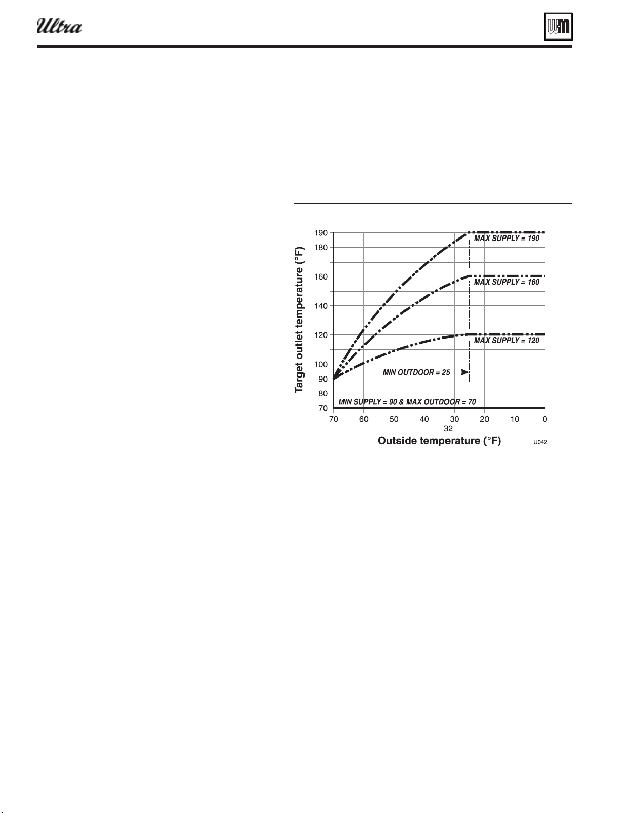
Part number 550-100-400/0119
100
f. An alternate method is to daisy chain the other
boilers. That is, connect the output of each to the
input of the next. Each of these boilers would be
set up as a Type 4 (see below), and each needs
its additional heat timer set for the desired delay
between boilers.
7. Type 4 — This assigns the boiler as a SHADOW boiler
in a multiple boiler system.
a. The boiler can be wired and setup to run in
parallel with the other SHADOW boilers as in
6c, above. Or they can be set up for sequential
operation following 6d, above.
b. When the boiler receives a 0–10 VDC input on
terminals P15 #5 and #6, it starts up and modu-
lates fi ring rate according to the signal.
c. If wired and setup per 6d above, it also starts its
additional heat delay timer immediately. When
the delay timing is reached, the U-Control sends
out a 0–10 VDC signal (on terminals P16 #1
and #2) for the next boiler.
d. The boiler uses the settings for Priority 1 while
receiving the 0–10 VDC signal.
ADVANCED SETUP –
PRIORITY 1, 2, 3
1. Priority 1, 2 and 3 refer to the three possible heating
inputs that can be handled by the U-Control.
2. Select the priority level desired for the application.
Priority 1 is usually assigned to domestic water heat-
ing, because of the need for quick response. Priority 2
and 3 usually used for space heating circuits.
3. Each of the three inputs has its own set of operating
parameters, programmed using the menus shown in
Figure 115, page 102 .
4. The inputs to the U-Control are:
a. Priority 1 — P11 #4 and #5, “heat demand 1”
b. Priority 2 — P15 #1 and #2, “heat demand 2”
c. Priority 3 — P15 #3 and #4, “heat demand 3”
ADVANCED SETUP –
SYSTEM TYPE
1. For each priority being used, select the appropriate
system type. See Figure 114, page 101 for system op-
tions and preset temperatures.
2. The temperature presets are chosen based on nor-
mal best setting for these systems. The temperature
values can be changed, if desired, under “TEMPERA-
TURES.”
ADVANCED SETUP –
TEMPERATURES
1. Setup desired temperatures for each of the priori-
ties used.
2. For an explanation of the target temperatures and
associated outdoor temperatures, see Figure 113 .
a. Outdoor temp for max target means the outdoor temperature
at which the target temperature reaches its maximum value. In
the example of Figure 113 , this occurs at 25 °F outside.
b. Outdoor temp for min target means the outdoor temperature
at which the target temperature reaches its minimum. In the
example of Figure 113 , this occurs at 70 °F.
c. Note that the reset lines are curved. The shape of this curve is
matched (or characterized) to the response of the system type
chosen to ensure the most effective reset operation.
Figure 113 Tpical outdoor reset cures
— The temperature must drop this
many degrees below target temperature for the boiler to come on.
— While the boiler is fi ring, as the
temperature increases above the target temperature, the boiler
fi ring rate is reduced. At this many degrees above the target tem-
perature, the boiler shuts down.
U-Control operation and setup — advanced (continued)
®
Series 4
gas-fired water boiler — Boiler Manual
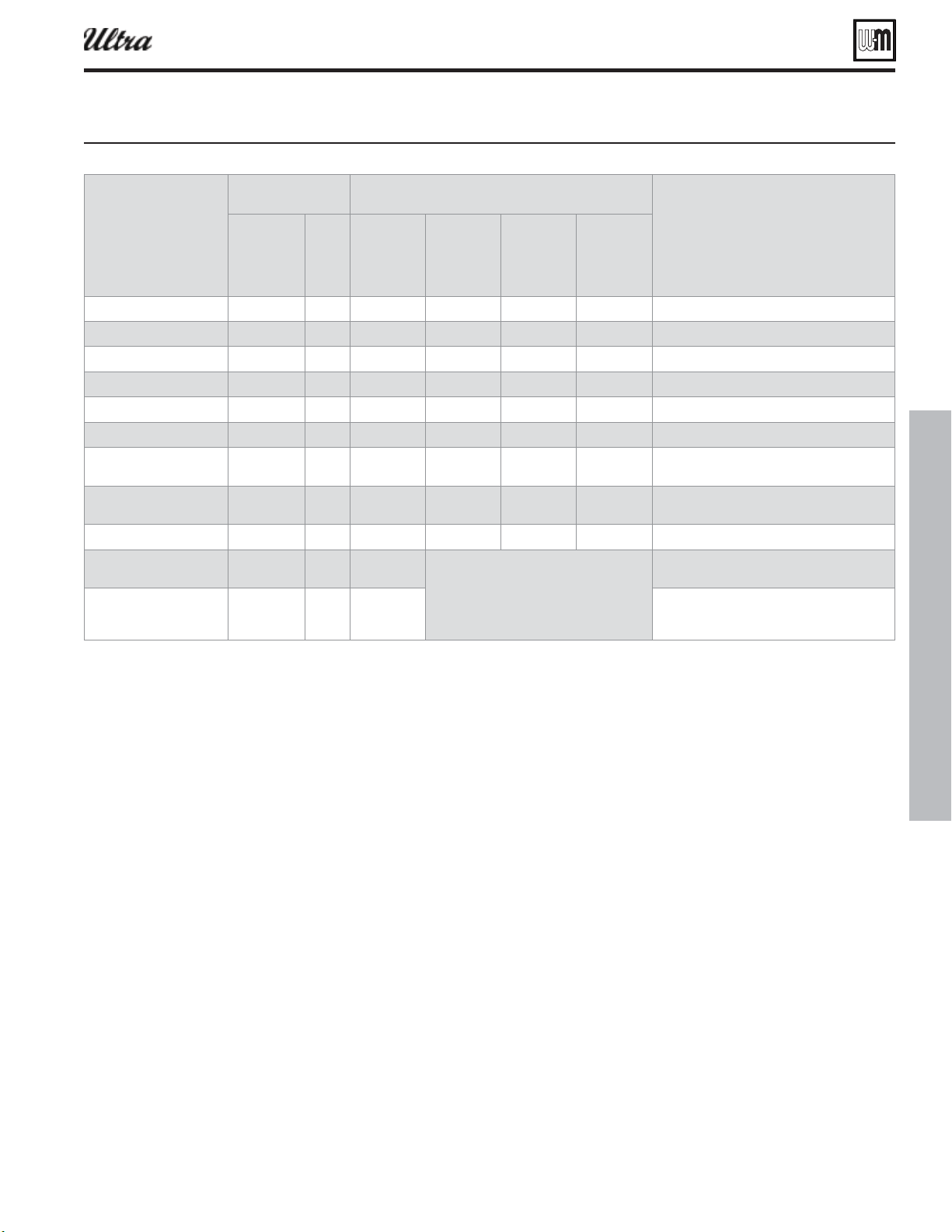
Part number 550-100-400/0119
101
ADVANCED SETUP –
CIRCULATOR EXERCISING
1. For each circulator, select whether you want the U-Control to
automatically start the circulator and run for 10 seconds for each
72-hour period of inactivity.
Figure 114 U-Control system types and preset parameters
8-character 3-char
a Taret
Temp
Outdoor
Temp
for a
Taret
in Taret
Temp
Outdoor
Temp
for in Taret
an-coil AN-COIL CL 190 0 140 70
inned tue aseoard IN BAS TB 180 0 130 70
Cast iron aseoard IN BAS CIB 180 0 120 70
Cast iron radiators AIATO CIR 180 0 120 70
adiant sla on rade A SLAB S 120 0 80 70
adiant thin sla A SLAB TS 140 0 80 70
adiant elo oor
staple up
ALOO SU 160 0 90 70
adiant aoe oor
sleeper sstem
ALOO A 140 0 90 70
Custom CUSTO CUS 190 0 70 70 oes not pass alon Addl eat emand
sstem OSTIC 190
heatin inores outdoor reset and
arm eather shutdon
U-Control modulates to sstem tempera-
ture sensors.
direct OSTIC 190 U-Control modulates to oiler temperature
sensors.
oes not pass alon Addl eat emand
ADVANCED SETUP –
FREEZE PROTECTION CIRCULATORS
1. This function automatically fi res the boiler at low fi re
and starts the circulators chosen if the heat exchanger
sensor detects a temperature less than 40 °F. The circu-
lators turn off when the temperature rises above 45 °F.
ADVANCED SETUP –
MAINTENANCE INFO
1. Use this section to enter contractor’s information and
to enter an automatic notice for maintenance (default
is 12 months). Because this shows on the display, it is an
automatic means of notifying the homeowner of need
for scheduled maintenance by the technician. Update the
screen reminder to reset for the next maintenance date.
U-Control operation and setup — advanced (continued)
®
Series 4
gas-fired water boiler — Boiler Manual
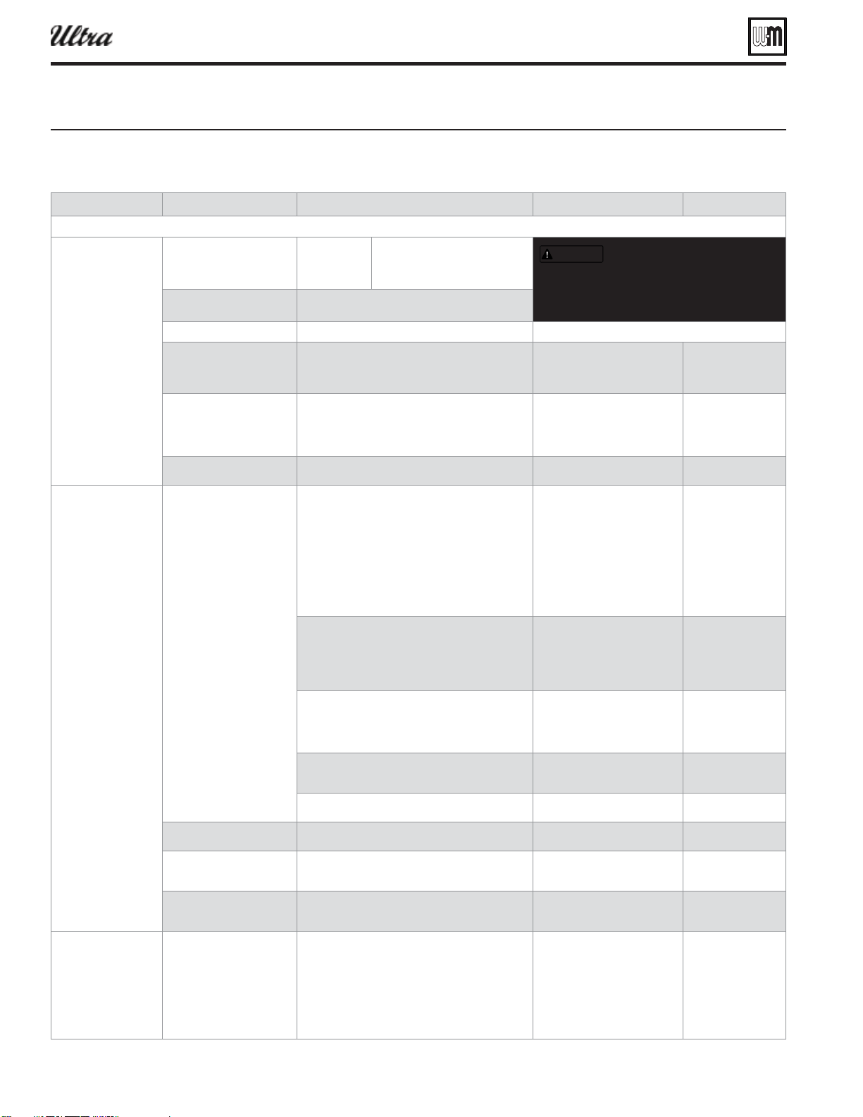
Part number 550-100-400/0119
102
U-Control operation and setup — advanced (continued)
Follow information at the bottom of each screen to navigate to next/previous screen or enter/save data
BOILER SETTINGS BOILER MODEL ##### 80
105
155
230
299
310
399
HIGH ALTITUDE ### NO
YES
HIGH TEMP LIMIT ###
WWSD SETTING ###
°F
ADJUST OUTDOOR ###
°F
###
###
ADD’L HEAT DEMAND
TYPE: ###########
OFF
TYPE 1 — ULTRA = PRIMARY HEAT SOURCE
TYPE 2 — ULTRA = BACKUP HEAT SOURCE
TYPE 3 — ULTRA = LEAD (0–10V OUTPUT)
TYPE 4 — ULTRA = SHADOW (0–10V INPUT)
ADD’L HEAT DEMAND
TIME: ### MINUTES
##
MINUTES
SYSTEM SETTINGS BOILER PRIORITY 1 SYSTEM TYPE: ### OFF
FAN COIL
FINNED TUBE BASEBOARD
CAST IRON BASEBOARD
CAST IRON RADIATOR
RADIANT — SLAB ON GRADE
RADIANT — THIN SLAB
RADIANT — ABOVE FLOOR
CUSTOM
DHW – DIRECT
DHW – SYSTEM
TEMPERATURES MAX SUPPLY: ### °F
MIN SUPPLY: ### °F
MAX OUTDOOR: ### °F
MIN OUTDOOR: ### °F
MODULATE ON DIFF: ### °F
MODULATE OFF DIFF:### °F
MIN SUPPLY, MAX
OUTDOOR AND MIN
OUTDOOR are not
shown for DHW types
TIMES MAX ON TIME: ### MIN
MIN ON TIME: ### MIN
BOOST INTERVAL: ### MIN
PRE PUMP TIME: ### SEC
POST PUMP TIME: ### SEC
not on Priority 3
not on Priority 1
CIRCULATORS: # # # CIRCULATOR 1: ###
CIRCULATOR 2: ###
CIRCULATOR 3: ###
ON/OFF
ON/OFF
ON/OFF
MAXIMUM RATE: ___%
MINIMUM RATE: ___%
### %
### %
BOILER PRIORITY 2
BOILER PRIORITY 3
SAME MENUS AS FOR PRIORITY 1
SAME MENUS AS FOR PRIORITY 1
CIRCULATOR EXERCISING CIRCULATOR 1: ###
CIRCULATOR 2: ###
CIRCULATOR 3: ###
ON/OFF
ON/OFF
ON/OFF
FREEZE PROTECT CIRCS CIRCULATOR 1: ###
CIRCULATOR 2: ###
CIRCULATOR 3: ###
ON/OFF
ON/OFF
ON/OFF
MAINTENANCE INFO NAME
PHONE
MODEL
CP#
INSTALLED
LAST DATE
NEXT DATE
INTERVAL SETTINGS
RESET REMINDER
################
###-###-####
ULTRA #####
##########
MM/DD/YY
MM/DD/YY
DD/MM/YY
## MONTHS
PRESS ENTER TO RESET
Figure 115 U-Control menus (press and hold the UP and DOWN arrow keys for 5 seconds to enter contractor menus)
®
Series 4
gas-fired water boiler — Boiler Manual
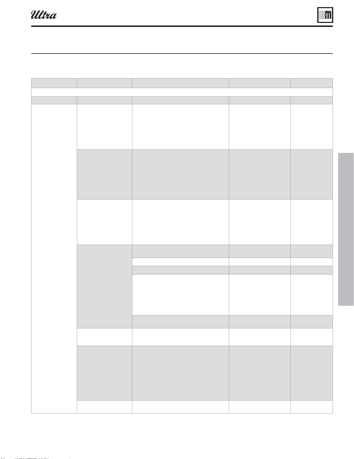
Part number 550-100-400/0119
103
U-Control operation and setup — advanced (continued)
Follow information at the bottom of each screen to navigate to next/previous screen or enter/save data
SET DATE AND TIME SET YR/MN/DAY/HR/MIN
DIAGNOSTICS TEMPERATURES STATUS: ##########
SYSTEM SUPPLY: ###°F
SYSTEM RETURN: ###°F
BOILER OUT1: ###°F
BOILER OUT2: ###°F
BOILER IN1: ###°F
FLUE 1: ###°F
FLUE 2: ###°F
OUTDOOR: ###°F
INPUTS STATUS: ##########
PRIORITY 1: ###
PRIORITY 2: ###
PRIORITY 3: ###
ANALOG IN: ####
MANUAL LIMIT: ######
AUTO LIMIT: ######
LOW WTR CUTOFF: ######
BLOWER TACH: ####RPM
FLAME SIGNAL: ###
OUTPUTS STATUS: ##########
GAS VALVE: ###
CIRCULATOR 1: ###
CIRCULATOR 2: ###
CIRCULATOR 3: ###
BLOWER SIGNAL: ###%
ADD’L HEAT DEMAND: ###
ALARM: ###
ANALOG OUT: ####
ERRORS CONTROL FAULT ###
IGNITION RETRIES ###
MANUAL RESET CNT ###
AUTO RESET CNT ###
LOCKOUT HISTORY 1 LOCKOUT HISTORY #
HH:MM AM MM/DD/YY
STATUS: ##########
MANUAL RESET
AUTO RESET
INPUTS
OUTPUTS
TEMPERATURES
LIST OF LOCKOUTS
LIST OF LOCKOUTS
INPUT STATUS
OUTPUT STATUS
TEMPERATURES
LOCKOUT HISTORY 2
LOCKOUT HISTORY 3
. . . SAME AS HISTORY 1
. . . SAME AS HISTORY 1
SOFTWARE VERSIONS DISPLAY V#.##
MAIN MICRO V#.##
SECOND MICRO V#.##
NOTE: Display will show
C#.## for CSD-1 control.
MANUAL TEST MODE STATUS: ##########
TARGET: ###°F
MODULATION: ###°F
SYSTEM SUPPLY: ###°F
SYSTEM RETURN: ###°F
BOILER OUT: ###°F
BOILER IN: ###°F
FLAME SIGNAL: ###
BLOWER SIGNAL: ###%
BLOWER TACH: ####RPM
FORCE RATE AUTO
MANUAL RESET PRESS ENTER TO RESET THE FOLLOWING
ERROR (SCREEN SHOWS A LIST OF ERRORS)
U-Control menus continued (press and hold the UP and DOWN arrow keys for 5 seconds to enter contractor menus)
®
Series 4
gas-fired water boiler — Boiler Manual
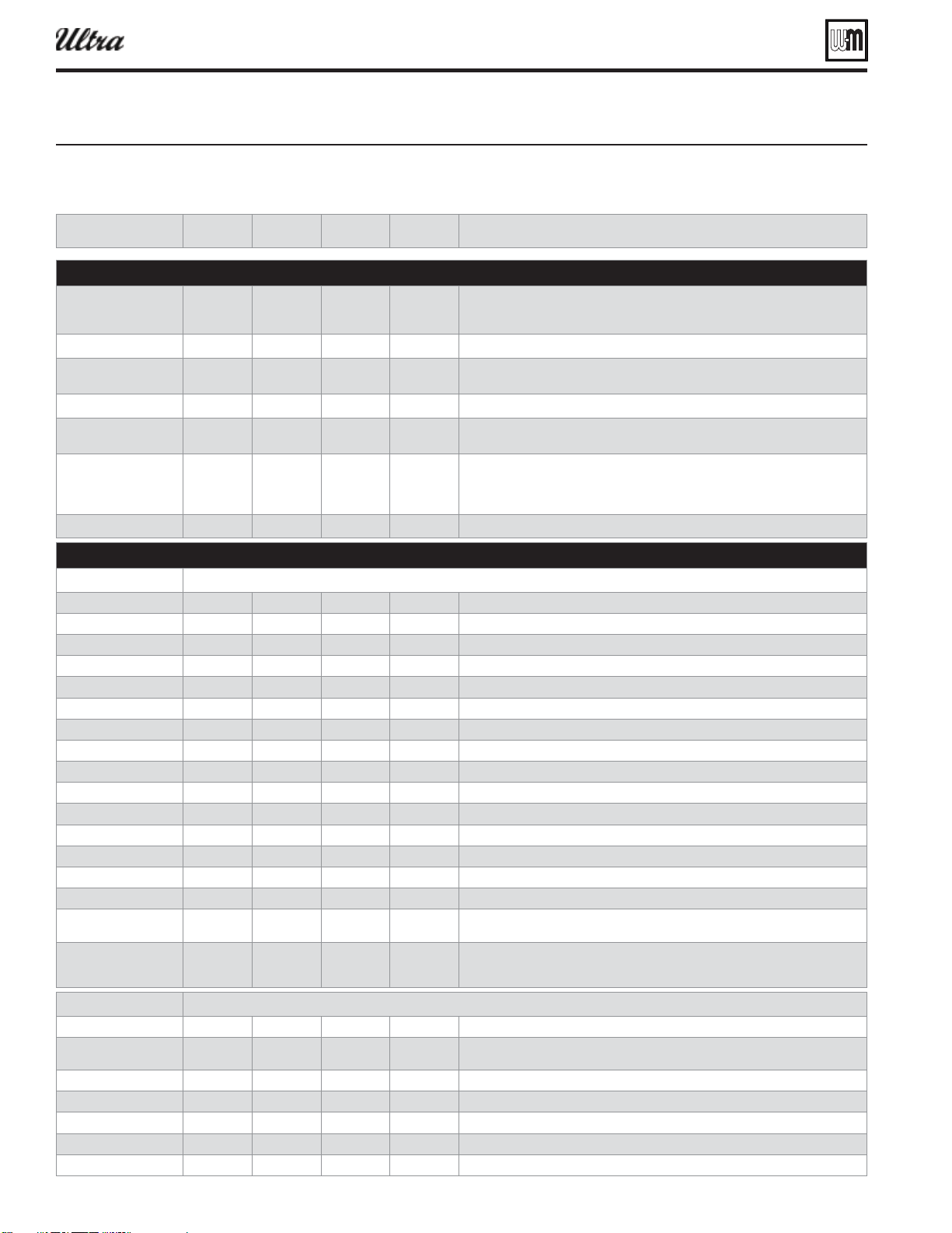
Part number 550-100-400/0119
104
U-Control operation and setup — advanced (continued)
Boiler Model
80, 105, 155,
230, 299, 310,
399
factory
. Adjusts blower speeds
and fl ame sense (Display will show “HA” after the model number if high altitude has been
selected, below.)
High Altitude
yes or no no Adjusts ignition and low fi re fan speed (for altitudes above 5, 500 feet only)
High Limit
°F 50 200 200 If boiler out temperature reaches this temperature boiler will lockout which requires a
manual reset
WWSD Temp
°F Off, 50 100 70 Boiler will not respond to heating calls above this outdoor temp
Adjust Outdoor
°F
(difference)
-10 +10 0 This value plus outdoor sensor reading equals outdoor temp (Use this setting to
compensate for solar gain or other factors that cause a shift in sensor temperature.)
Add’l Heat Demand Type
Types Off Type 4 Off Type 1 — Ultra is primary source, starts secondary after delay (requires system sensors)
Type 2 — Ultra is secondary source, starts primary immediately
Type 3 — Boilers operate in parallel, Ultra boiler is LEAD, outputs 0–10 VDC to others
Type 4 — Boilers operate in parallel, Ultra boiler is SHADOW, receives 0–10 VDC input
Add’l Heat Demand Time
minutes 0 240 0 Delay before bringing on additional heating appliances
System Type
Types Off Custom DHW - direct DHW-direct doesn’t use ODR, boost, or Add’l heat demand output
Max Supply
°F 60 190 190 Boiler enters manual reset lockout at 200°F
Min Supply
°F 60 190 N/A N/A - DHW does not use reset
Max OD Reset
°F 50 100 N/A N/A - DHW does not use reset
Min OD Reset
°F –20 50 N/A N/A - DHW does not use reset
Modulate On Diff
°F 2 10 5 Boiler turns on if temperature drops below target minus differential on
Modulate Off Diff
°F 2 10 5 Boiler shuts down if modulates past target plus differential off
Max On Time
minutes off 240 30 Longest time boiler will satisfy this system before switching to an active lower priority
Min On Time
————Priority 1 does not have this setting
Boost Interval
minutes off 240 N/A
(not used) When operating on ODR increases target 10F when this time expires until reaching MAX
Prepump Time: ### SEC
seconds 0 240 20 Additional time to run circulators longer than standard 10 second time
Postpump Time: ### SEC
seconds off 240 30 Circulator run time after call for heat ends
Circulator 1
on-off off on on Circulator activates on this call for heat if on
Circulator 2
on-off off on off Circulator activates on this call for heat if on
Circulator 3
on-off off on off Circulator activates on this call for heat if on
Maximum Rate
%Rate 21% 100% 96% Boiler Model and altitude specifi c (derated to 96% from factory)
NOTE: Adjusting boiler fi ring rate will affect AFUE rating.
Minimum Rate
%Rate 20% 99% 33% (80-
299/310)
20% (399)
Boiler Model and altitude specifi c
System Type
Types FTB Finned-Tube Baseboard
Max Supply
°F 60 190 180 Highest target the control will calculate based on outdoor temperature
Target temperature if outdoor sensor is not detected (manual reset lockout at 200°F)
Min Supply
°F 60 190 130 Lowest target the control will calculate based on outdoor air temperature
Max OD Reset
°F 50 100 70 Outdoor air temperature that forces the minimum supply water to be target temperature
Min OD Reset
°F –20 50 0 Outdoor air temperature that forces the maximum supply water to be target temperature
Modulate On Diff
°F 2 10 5 Boiler turns on if temperature drops below target minus differential on
Modulate Off Diff
°F 2 10 5 Boiler shuts down if modulates past target plus differential off
Figure 116 U-Control setup options see iure pae for location in menu seuence
®
Series 4
gas-fired water boiler — Boiler Manual
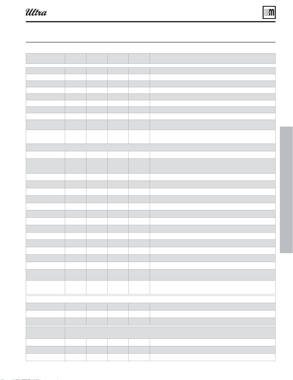
Part number 550-100-400/0119
105
U-Control operation and setup — advanced (continued)
Max On Time
minutes off 240 30 Longest time boiler will satisfy this system before switching to an active lower priority
Min On Time
minutes off 240 15 Time boiler will satisfy this system before switching to the next active priority
Boost Interval
minutes off 240 off When operating on ODR increase target 10F when this time expires until reaching MAX
Prepump Time: ### SEC
seconds 0 240 20 Additional time to run circulators longer than standard 10 second time
Postpump Time: ### SEC
seconds off 240 30 Circulator run time after call for heat ends
Circulator 1
on-off off on off Circulator activates on this call for heat if on
Circulator 2
on-off off on on Circulator activates on this call for heat if on
Circulator 3
on-off off on on Circulator activates on this call for heat if on
Maximum Rate
%Rate 21% 100% 96% Boiler Model and altitude specifi c (derated to 96% from factory)
NOTE: Adjusting boiler fi ring rate will affect AFUE rating.
Minimum Rate %Rate 20% 99% 33% (80-
299/310)
20% (399)
Boiler Model and altitude specifi c
System Type
Ty p e s C us t o m
Max Supply
°F 60 190 190 Highest target the control will calculate based on outdoor temperature
Target temperature if outdoor sensor is not detected
(manual reset lockout at 200°F)
Min Supply
°F 60 190 70 Lowest target the control will calculate based on outdoor air temperature
Max OD Reset
°F 50 100 70 Outdoor air temperature that forces the minimum supply water to be target temperature
Min OD Reset
°F –20 50 0 Outdoor air temperature that forces the maximum supply water to be target temperature
Modulate On Diff
°F 2 10 5 Boiler turns on if temperature drops below target minus differential on
Modulate Off Diff
°F 2 10 5 Boiler shuts down if modulates past target plus differential off
Max On Time
————Priority 3 does not have this setting
Min On Time
minutes off 240 15 Time boiler will satisfy this system before switching to the next active priority
Boost Interval
minutes off 240 off When operating on ODR increase target 10F when this time expires until reaching MAX
Prepump Time: ### SEC
seconds 0 240 20 Additional time to run circulators longer than standard 10 second time
Postpump Time: ### SEC
seconds off 240 30 Circulator run time after call for heat ends
Circulator 1
on-off off on on Circulator activates on this call for heat if on
Circulator 2
on-off off on on Circulator activates on this call for heat if on
Circulator 3
on-off off on on Circulator activates on this call for heat if on
Maximum Rate
%Rate
21% 100%
96% Boiler Model and altitude specifi c (derated to 96% from factory)
NOTE: Adjusting boiler fi ring rate will affect AFUE rating.
Minimum Rate
%Rate
20% 99% 33% (80-
299/310)
20% (399)
Boiler Model and altitude specifi c
Circulator 1
on-off off on on Circulators exercise 10 seconds every 72 hours of inactivity if on
Circulator 2
on-off off on on Circulators exercise 10 seconds every 72 hours of inactivity if on
Circulator 3
on-off off on on Circulators exercise 10 seconds every 72 hours of inactivity if on
Circulator 1
on-off off on off If HxOut sensor out falls below 40F boiler fi res low and turns on this circ until 45F
Circulator 2
on-off off on on If HxOut sensor out falls below 40F boiler fi res low and turns on this circ until 45F
Circulator 3
on-off off on off If HxOut sensor out falls below 40F boiler fi res low and turns on this circ until 45F
U-Control setup options see iure pae for location in menu seuence continued
®
Series 4
gas-fired water boiler — Boiler Manual
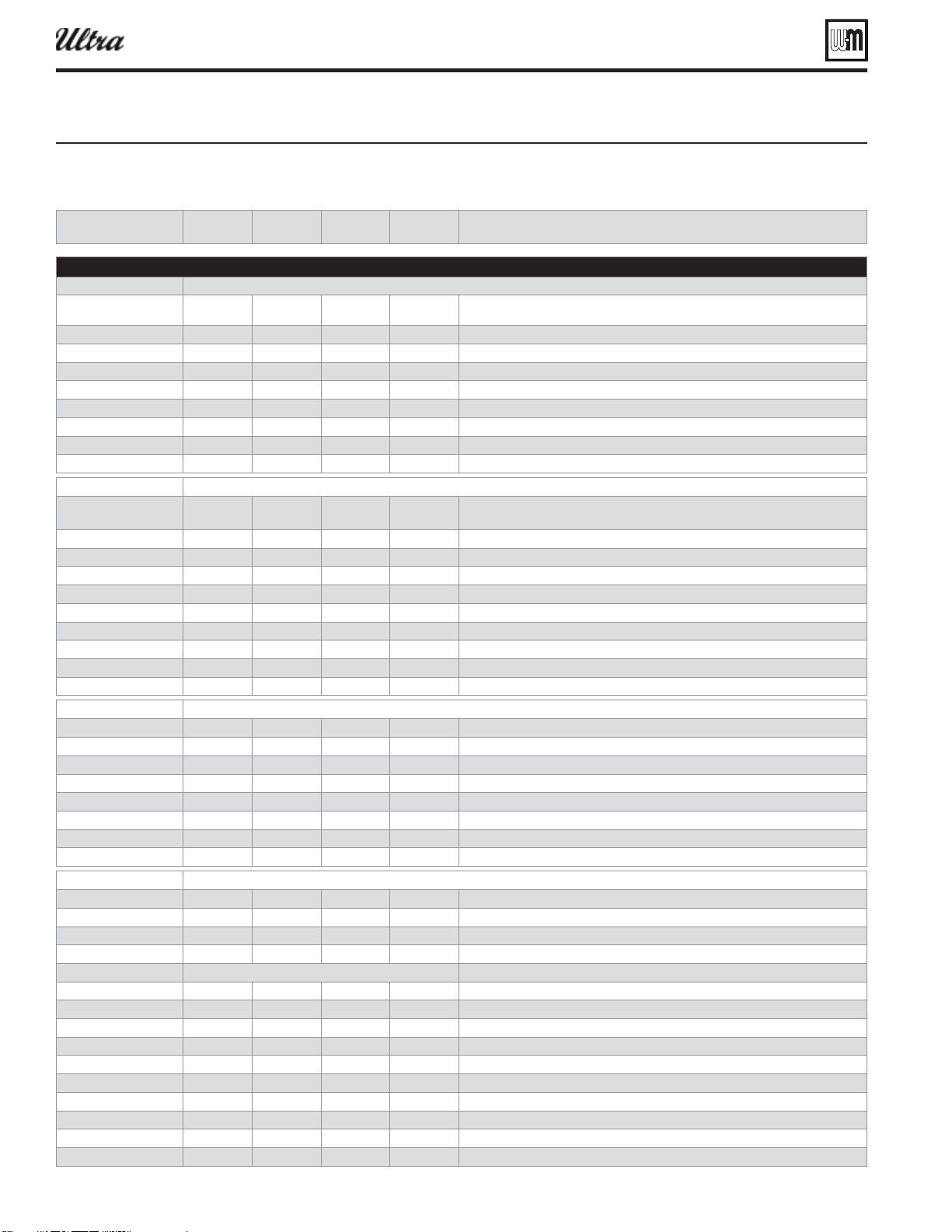
Part number 550-100-400/0119
106
U-Control operation and setup — advanced (continued)
Figure 117 U-Control diagnostic inform ation see iure pae for location in menu seuence
Status
Text data Current operating status of the boiler. Prepurge, Ignition, Name of the system Type being
satisfi ed, post purge, Warm Weather Shutdown, Trouble
System Supply
°F data Temperature of the remote system supply sensor
System Return
°F data Temperature of the remote system return sensor
Boiler Out1
°F data Temperature of the fi rst sensing element of the boiler’s heat exchanger outlet sensor
Boiler Out2
°F data Temperature of the second sensing element of the boiler’s heat exchanger outlet sensor
Boiler In1
°F data Temperature of the boiler’s heat exchanger inlet sensor
Flue1
°F data Temperature of the fi rst sensing element of the boiler’s fl ue gas sensor
Flue2
°F data Temperature of the second sensing element of the boiler’s fl ue gas sensor
Outdoor
°F data Temperature of the remote outdoor air temperature sensor
Status
Text data Current operating status of the boiler. Prepurge, Ignition, Name of the system Type being
satisfi ed, post purge, Warm Weather Shutdown, Trouble
Priority 1
on-off data Call for heat status on Priority 1 Input
Priority 2
on-off data Call for heat status on Priority 2 Input
Priority 3
on-off data Call for heat status on Priority 3 Input
Analog Input
vdc data Value of 0–10 VDC input signal on P15 #5 and #6
Manual Limit
open-closed data External manual limit P13-1 & P13-2
Auto Limit
open-closed data External auto limit P13-3 & P13-4
Low Wtr Cutoff
open-closed data Low water cutoff device on P12-3 & P12-4
Blower Tach
rpm data Feedback from blower sensor
Flame Signal
no units data Number indicating the presence and quality of the fl ame used to shutdown boiler
Gas Valve
on-off data Control’s gas valve circuit status
Circulator 1
on-off data Control’s circulator 1 relay status
Circulator 2
on-off data Control’s circulator 2 relay status
Circulator 3
on-off data Control’s circulator 3 relay status
Blower Signal
% of rate data Control’s signal controlling the blower speed
Add’l Heat Demand
on-off data Control’s signal controlling the additional heat demand
Alarm
on-off data Control’s alarm contact status
Analog Output
vdc data Value of 0–10 VDC output signal on P16 #1 and #2
Control Fault
# 0 Displays number of control faults
Ignition Retries
# 0 Displays number of ignition attempts boiler is currently on
Manual Reset Cnt
# 0 Displays number of manual reset lockouts since last cleared
Auto Reset Cnt
# 0 Displays number of auto reset lockouts since last cleared
Lockout History 1
Choose this to view the most recent error recorded
Time & Date
text data Displays time and date that lockout occurred
Status
text data Displays what the status of the boiler at the time of the error
Manual Reset
yes or none data Choose this to view the details of manual reset lockouts
Auto Reset
yes or none data Choose this to view the details of auto reset lockouts
Inputs
menu menu Choose this to view the status of the Boiler Inputs at the time of the error
Outputs
menu menu Choose this to view the status of the Boiler Outputs at the time of the error
Temperatures
menu menu Choose this to view the Boiler Temperatures at the time of the error
Lockout History 2
Choose this to view the second most recent error recorded
Time & Date
text data Displays time and date that lockout occurred
Status
text data Displays what the status of the boiler at the time of the error
®
Series 4
gas-fired water boiler — Boiler Manual
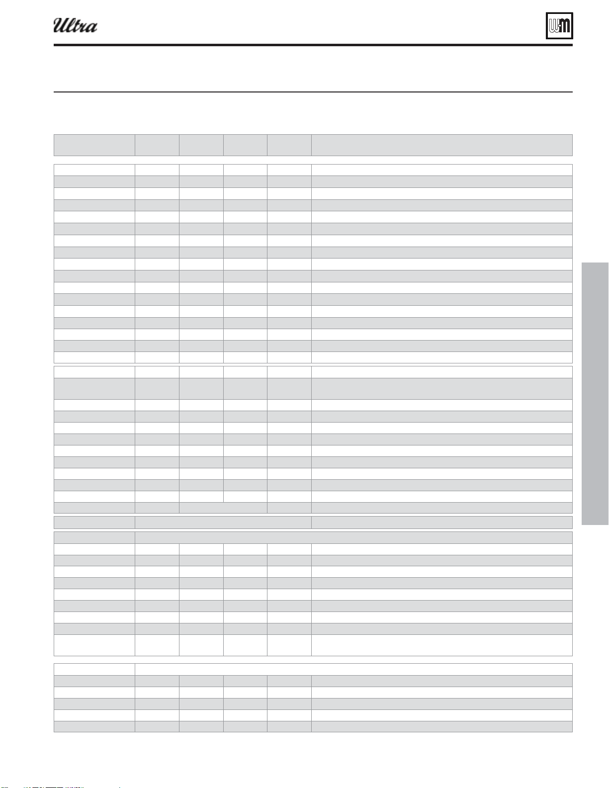
Part number 550-100-400/0119
107
U-Control operation and setup — advanced (continued)
U-Control diagnostic inform ation see iure pae for location in menu seuence continued
Manual Reset
yes or none data Choose this to view the details of manual reset lockouts
Auto Reset
yes or none data Choose this to view the details of auto reset lockouts
Inputs
menu menu Choose this to view the status of the Boiler Inputs at the time of the error
Outputs
menu menu Choose this to view the status of the Boiler Outputs at the time of the error
Temperatures
menu menu Choose this to view the Boiler Temperatures at the time of the error
Lockout History 3
Choose this to view the third most recent error recorded
Time & Date
text data Displays time and date that lockout occurred
Status
text data Displays what the status of the boiler at the time of the error
Manual Reset
yes or none data Choose this to view the details of manual reset lockouts
Auto Reset
yes or none data Choose this to view the details of auto reset lockouts
Inputs
menu menu Choose this to view the status of the Boiler Inputs at the time of the error
Outputs
menu menu Choose this to view the status of the Boiler Outputs at the time of the error
Temperatures
menu menu Choose this to view the Boiler Temperatures at the time of the error
Display #.## format data Software version of the microprocessor on the display circuit board
Main Micro #.## format data Software version of the main microprocessor on the control circuit board
Second Micro #.## format data Software version of the second microprocessor on the control circuit board
Status text data Current operating status of the boiler. Prepurge, Ignition, Name of the system Type being
satisfi ed, post purge, Warm Weather Shutdown, Trouble
Target °F data Calculated target temperature based on outdoor temp or the max setpoint if no ODR
Modulation °F data Temperature of the sensor the boiler is using to base its modulation
System Supply °F data Temperature of the remote mounted system water supply sensor
System Return °F data Temperature of the remote mounted system water return sensor
Boiler Out °F data Temperature of the outlet sensor on the boiler heat exchanger
Boiler In °F data Temperature of the inlet sensor on the boiler heat exchanger
Flame Signal no units data Number indicating the presence and quality of the fl ame used to shutdown boiler
Blower Signal % of rate data Control’s output to the blower
Blower Tach rpm data Blower’s feedback to the control
Force Rate Low, Med, High, or Auto Auto Used to manually force a rate during a call for heat. Choose auto for normal operation.
Reset selected condition
Name text blank Contractor name to appear in maintenance reminders and during lockouts
Phone text blank Contractor phone number
Model text blank Displays the boiler model selected in the boiler setup
CP Number text blank Enter the CP# of the boiler
Installed text blank Enter the date the boiler was installed
Last Date text data Date automatically entered when Reset Reminder is choose by contractor
Next Date text data Date automatically calculated when Reset Reminder is selected by contractor
Interval Settings months 6 24 12 Contractor selects maintenance reminder frequency based on service history
Reset Reminder menu menu Contractor selects this to update Last maintenance Date and Next Date. Homeowner uses
this to ignore the reminder and update only the Next Date.
Year text 2017 Set year (homeowner or contractor)
Month text 1 Set month (homeowner or contractor)
Day text 1 Set day (homeowner or contractor)
Hour text 12 Set hour (homeowner or contractor)
Minute text 0 Set minute (homeowner or contractor)
®
Series 4
gas-fired water boiler — Boiler Manual
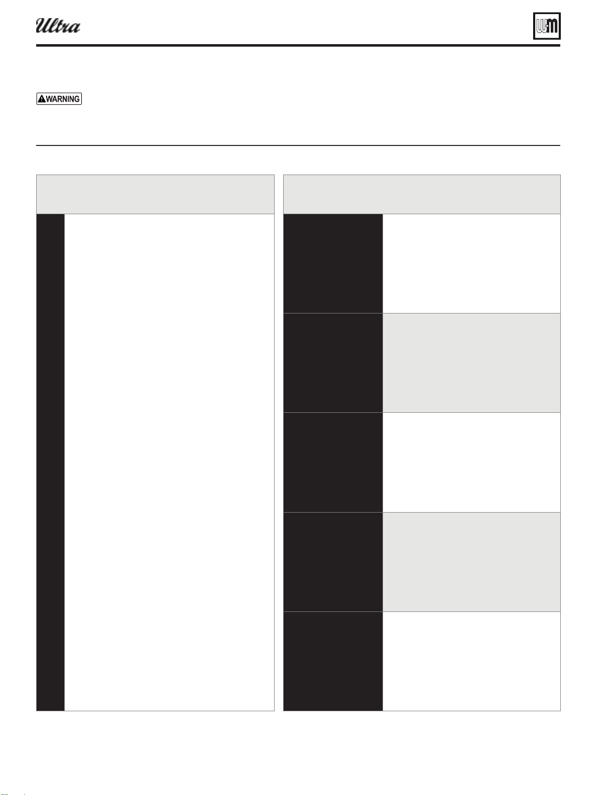
Part number 550-100-400/0119
108
Annual startup and general maintenance
Figure 118Serice and maintenance schedules
Service technician
(see following pages for instructions)
Owner maintenance
(see Ultra User’s Information Manual for instructions)
General:
Additional if combustion or
performance indicate need:
Review:
Follow the service and maintenance procedures given throughout this manual and in component literature shipped
with the boiler. Failure to perform the service and maintenance could result in damage to the boiler or system. Failure to
follow the directions in this manual and component literature could result in severe personal injury, death or substantial
property damage.
®
Series 4
gas-fired water boiler — Boiler Manual
Part number 550-100-400/0119
109
Annual startup
HANDLING CERAM IC FIBER
MATERIALS
REMOVING BURNER GASKET or
COVER PLATE INSULATION
The Ultra burner gasket (models 80
and 105) and cover plate insula-
tion (all models) contain ceramic
fi ber material. Ceramic fi bers can
be converted to cristobalite in very
high temperature applications. The
International Agency for Research
on Cancer (IARC) has concluded,
“Crystalline silica inhaled in the
form of quartz or cristobalite from
occupational sources is carcinogenic
to humans (Group 1).”:
■ Avoid breathing dust and contact with skin
and eyes.
Use NIOSH certified dust respirator
(N95). This type of respirator is based on
the OSHA requirements for cristobalite
at the time this document was written.
Other types of respirators may be needed
depending on the job site conditions.
Current NIOSH recommendations can
be found on the NIOSH web site at http://
www.cdc.gov/niosh/homepage.html.
NIOSH approved respirators, manufactur-
ers, and phone numbers are also listed on
this web site.
Wear long-sleeved, loose fi tting clothing,
gloves, and eye protection.
■ Apply enough water to the combustion
chamber lining or base insulation to prevent
airborne dust.
■ Remove combustion chamber lining or base
insulation from the boiler and place it in a
plastic bag for disposal.
■ Wash potentially contaminated clothes
separately from other clothing. Rinse clothes
washer thoroughly.
NIOSH stated First Aid
■ Eye: Irrigate immediately
■ Breathing: Fresh air.
FIRST-YEAR SPECIAL INSPECTION
. This kit includes a
heat exchanger cover plate gasket, burner gasket (80
and 105 only), new ignitor, and ignitor gasket. See list-
ing in Replacement parts section of this manual. These
parts must be on hand when you perform the fi rst-year
inspection in the event they must be replaced.
Failure to replace the items above when needed could
result in severe personal injury, death or substantial
property damage.
after the boiler is installed, perform
a fi rst-year inspection of the boiler. This must include the fol-
lowing .
a. Remove the heat exchanger cover plate (see page 112 for
instructions on removal and replacement).
b. Inspect the heat exchanger and clean if necessary (see “Clean-
ing the heat exchanger — pin side when required,” page 125,
and all referenced illustrations and instructions).
c. Inspect the cover plate insulation and gasket. Replace if not
in good condition.
d. Remove the burner and inspect carefully. Clean the burner
thoroughly using a vacuum cleaner and a soft brush if
needed. Make sure there is no blockage or accumulation of
debris in the burner or the burner ports. Replace the burner
if necessary.
e. Models 80 and 105 only — inspect the burner gasket, and
replace if the gasket is not in good condition. Make sure the
burner is clean. Then securely fasten it tightly to the cover
plate.
f. Disconnect condensate trap and drain lines. Inspect, then
fl ush thoroughly.
2. Determine follow-up maintenance and service needs based on
the condition of the heat exchanger and condensate lines.
a. If the heat exchanger shows substantial fouling, or if con-
densate lines show accumulation of sediment, schedule a
follow-up service call to perform the fi rst-year inspection
again, sooner than the normal twelve months between.
b. Heavy fouling of the exchanger or condensate lines indicates
possible combustion air contamination. Inspect the air in-
take area carefully, and remove possible contaminants. See
Figure 11, page 16 , for products to avoid.
You must eliminate causes of corrosion and contami-
nation to ensure reliable operation of the boiler and
system.
®
Series 4
gas-fired water boiler — Boiler Manual
Part number 550-100-400/0119
110
Annual startup (continued)
The boiler should be inspected and
started annually, at the beginning of the
heating season, only by a qualifi ed service
technician. In addition, the maintenance
and care of the boiler designated in Fig-
ure 118, page 108 and explained on the
following pages must be performed to
assure maximum boiler effi ciency and
reliability. Failure to service and main-
tain the boiler and system could result
in equipment failure.
Electrical shock hazard — Turn off power
to the boiler before any service operation
on the boiler except as noted otherwise
in this instruction manual. Failure to
turn off electrical power could result in
electrical shock, causing severe personal
injury or death.
Address reported problems
1. Inspect any problems reported by owner and correct before
proceeding.
Inspect boiler area
1. Verify that boiler area is free of any combustible materials,
gasoline and other fl ammable vapors and liquids.
2. Verify that air intake area is free of any of the contaminants
listed on page 16 of this manual. If any of these are present
in the boiler intake air vicinity, they must be removed. If
they cannot be removed, reinstall the air and vent lines per
this manual.
Inspect boiler interior & door gaskets
1. Remove jacket front door and inspect interior of boiler.
2. Visually inspect the door gaskets. Make sure all are in good
condition. Obtain replacements if any gasket is damaged.
Door gaskets must be intact, and must provide a
reliable seal. Replace any damaged gasket.
3. Remove the venturi air inlet silencer and clean if necessary.
Replace silencer.
4. Vacuum any sediment from the inside of the boiler and
components. Remove any obstructions.
Do not use solvents to clean any of the boiler
components. The components could be damaged,
resulting in unreliable or unsafe operation.
Clean condensate trap
1. Loosen condensate trap line hose clamps and remove trap
line.
2. Empty water from trap line and inspect. Flush out if needed
with fresh water.
3. Check condensate elbow and tee and condensate line to drain.
Flush if necessary to clean.
4. Reinstall condensate trap line and tighten hose clamps.
5. Fill trap with fresh water by pouring into upturned end of
PVC condensate tee.
Check all piping for leaks
Eliminate all system or boiler leaks. Continual fresh
make-up water will reduce boiler life. Minerals
can build up in sections, reducing heat transfer,
overheating heat exchanger, and causing heat
exchanger failure. Leaking water may also cause
severe property damage.
1. Inspect all water and gas piping and verify to be leak free.
2. Look for signs of leaking lines and correct any problems
found.
3. Check gas line using procedure on page 29 .
Check air openings
1. Verify that combustion and ventilation air openings to the
boiler room and/or building are open and unobstructed.
Check operation and wiring of automatic combustion air
dampers, if used.
2. Verify that boiler vent discharge and air intake are clean and
free of obstructions.
Flue vent system and air piping
1. Visually inspect entire fl ue gas venting system and combus-
tion air piping for blockage, deterioration or leakage. Repair
any joints that show signs of leakage in accordance with vent
manufacturer’s instructions. When air is ducted to boiler,
verify that air inlet hose is connected and properly sealed.
Failure to inspect for the above conditions and have
them repaired can result in severe personal injury
or death.
Check water system
1. Verify all system components are correctly installed and
operational.
2. Check the cold fi ll pressure for the system. Verify it is correct
(usually around 12 psig).
3. Watch the system pressure as the boiler heats up (during
testing) to ensure pressure doesn’t rise too high. Excessive
pressure rise indicates expansion tank sizing or performance
problem.
®
Series 4
gas-fired water boiler — Boiler Manual

Part number 550-100-400/0119
111
Annual startup (continued)
4. Inspect automatic air vents and air separators. Remove air vent caps
and briefl y press push valve to fl ush vent. Reinstall caps. Make sure
vents do not leak. Replace any leaking vents.
5. Check system water chemistry (pH, hardness and inhibitor level). See
page 35 .
Check expansion tank
1. Expansion tanks provide space for water to move in and out as the
heating system water expands due to temperature increase or contracts
as the water cools. Tanks may be open, closed or diaphragm or bladder
type. See page 11 of this manual for suggested location of expansion
tanks and air eliminators.
Open-type — located above highest radiator or baseboard unit,
usually in the attic or closet. Has a gauge glass and overfl ow pipe
to a drain.
Closed-type — welded gas tight and located above boiler. Tank is
partially fi lled with water, leaving an air cushion for expansion.
Make sure this type of tank is fi tted with a tank fi tting, such
gravity circulation of air-saturated tank water back to the system
and prevents the air from bubbling up through the water as it
returns from the system.
Do not use automatic air vents in systems with closed-type
tanks. The air will escape from the system instead of returning
to the tank. Eventually, the tank will waterlog and no longer con-
trol pressurization. The boiler relief valve will weep frequently.
— welded gas tight with a rubber
membrane to separate the tank pressurizing air and the water. May
be located at any point in the system, but most often found near
the boiler.
Systems with this type of expansion tank require at least one
automatic air vent, preferably located on top of an air elimina-
tor, as shown in examples in this manual.
2. If relief valve has tended to weep frequently, the expansion tank may
be waterlogged or undersized.
— tank is most likely waterlogged. Install a
tank fi tting if not already installed. Then check fi ll level per fi tting
manufacturer’s instructions. If fi ll level is correct, check tank size
against manufacturer’s instructions. Replace with a larger tank if
necessary.
— fi rst, check tank size to be sure it
is large enough for the system. If size is too small, add additional
tank (or tanks) as necessary to provide suffi cient expansion. If tank
size is large enough, remove tank from system and check charge
pressure (usually 12 psig for residential applications). If tank won’t
hold pressure, membrane has been damaged. Replace tank.
Inspect ignition electrode
1. Remove the ignition electrode from the boiler heat
exchanger access cover.
2. Remove any white oxides accumulated on the
ignition electrode using steel wool. If the ignition
electrode cannot be cleaned satisfactorily, replace
ignitor with a new one.
3. Reinstall ignition electrode, making sure gasket is
in good condition and correctly positioned.
4. Make sure the electrodes are parallel to each other.
Check ignition wiring
1. Check ignition cable electrical resistance. A good
cable will have resistance between 900 and 1000
ohms. Replace if not acceptable.
2. Inspect boiler ground wire from heat exchanger
access cover to ground terminal strip.
3. Verify all wiring is in good condition and securely
attached.
4. Check ground continuity of wiring using continu-
ity meter.
5. Replace ground wires if results are not satisfactory.
Check all boiler wiring
1. Inspect all boiler wiring, making sure wires are in
good condition and securely attached.
Check control settings
1. Use the U-Control display to navigate through all
settings. Adjust settings if necessary.
2. Check settings of external limit controls (if any)
and adjust if necessary.
Perform startup and checks
1. Start boiler and perform checks and tests specifi ed
in this manual.
2. Verify cold fi ll pressure is correct and that operating
pressure does not go too high.
3. Complete the check-out procedure on page 42 .
®
Series 4
gas-fired water boiler — Boiler Manual
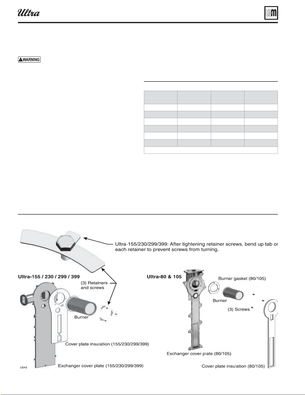
Part number 550-100-400/0119
112
Annual startup (continued)
Figure 120Burner asseml
Check burner fl ame
The boiler contains ceramic fi ber materials.
Use care when handling these materials per
instructions on page 109 of this manual. Fail-
ure to comply could result in severe personal
injury.
1. Inspect fl ame through observation window using the
procedure on page 40 .
2. If fl ame is unsatisfactory at either high fi re or low fi re,
turn off boiler and allow boiler to cool down. Then
remove burner and clean it thoroughly using a vacuum
cleaner or compressed air. Do not use compressed air to
clean burner if performed inside a building.
3. To access the burner, remove the heat exchanger cover
plate following the procedure beginning on page 125 .
4. When replacing burner, ensure gasket is in good condi-
tion and correctly positioned. After tightening the three
retainer screws, bend up the retainer tabs as shown in
Figure 120 to prevent screw rotation.
5. Reattach the cover plate using the method given in
Figure 126, page 126 or Figure 128, page 127 .
6. After servicing, reinstall boiler components. Retest
boiler.
Check fl ame signal
1. Navigate to Diagnostics/Inputs on the U-Control display (see
Figure 115, page 102 ). The fl ame signal value must be at least 20
above the Shutdown values given in Figure 119 .
Figure 119
lame sinal shutdon alues
80
80
80
NOTE: “HA” means high altitude, 5500 feet or more above seal level.
2. If the fl ame signal drops to less than 20 above the Shutdown
values, the U-Control will attempt to correct by increasing the
boiler fi ring rate to increase fl ame signal.
3. A lower fl ame signal may indicate a fouled ignitor or damaged ig-
nitor insulation. If cleaning the ignitor does not improve, ground
wiring is in good condition, and ground continuity is satisfactory,
replace the ignitor.
®
Series 4
gas-fired water boiler — Boiler Manual
Part number 550-100-400/0119
113
Annual startup (continued)
4. If fl ame signal still remains low, inspect the vent and air
piping. Then inspect the heat exchanger, following the proce-
dures given in this manual for removal and reinstallation of
the head exchanger cover plate and other boiler components.
Clean the exchanger as described in this manual if necessary.
Check blower speeds
1. For installations at altitudes above 5,500 feet, make sure the
control is set up for high altitude in the boiler setup menu.
The U-Control module automatically adjusts low fi re and
ignition rates to compensate for high altitude conditions.
2. For installations below 5,500 feet, high altitude should NOT
be enabled.
3. Use the U-Control display to navigate to Manual test mode
(see Figure 115, page 102 ).
4. Set the fi ring rate to MINIMUM (low fi re).
5. Write down the blower RPM value shown and compare to
the value in Figure 121 . The value should no less than the
“Minimum setting” and no higher than the Ignition “Fac-
tory setting” listed. Low fi re rate (and corresponding blower
speed) is adjusted in the boiler setup menu.
6. Set the fi ring rate to MEDIUM (ignition rate).
7. Write down the blower RPM value. It should be within 200
RPM of the value listed in Figure 121 .
8. Set the fi ring rate to MAXIMUM (high fi re).
9. Write down the blower RPM value. It should be within 200
RPM of the value given in Figure 121 .
10. If any of the values are outside the ranges listed in the previous
steps, contact the factory for technical assistance.
Check fl ue gas temperature
1. Set the boiler to high fi re. Then adjust the U-Control mod-
ule display to view fl ue gas temperature and boiler return
temperature.
2. The fl ue gas temperature should be no more than 54 °F higher
than the boiler return temperature.
3. If the fl ue temperature is higher than this, shut down the
boiler, allow to cool, and follow the procedure starting on
page 125 to clean the Nanogate coatedheat exchanger.
Figure 121 irin rates and correspondin loer speeds lo re inition and hih re for altitudes up to feet
% RPM Btu/Hr % RPM Btu/Hr % RPM Btu/Hr % RPM Btu/Hr % RPM Btu/Hr % RPM Btu/Hr
Low fi re
inimum settin
20 1,300 16,000 20 1,300 21,000 20 1,300 31,000 20 1,300 46,000 20 1,400 62,000 20 1,520 79,800
actor settin
33 1,983 26,400 33 1,983 34,650 33 1,983 51,150 33 1,983 75,900 33 2,156 102,300 20 1,520 79,800
ih altitude
33 1,983 26,400 33 1,983 34,650 33 1,983 51,150 33 1,983 75,900 30 1,981 93,000 28 2,002 111,720
Ignition (“Medium” setting in manual test mode)
actor settin
47 2,300 37,600 47 2,300 49,350 47 2,300 72,850 47 2,300 108,100 36 2,330 111,600 33 2,303 131,670
ih altitude
62 3,500 49,600 62 3,500 65,100 62 3,500 96,100 62 3,500 142,600 51 3,202 158,100 40 2,725 159,600
High fi re
(adjust if desired to match maximum system load — High fi re % rate = Max heat load / Boiler output)
actor settin
94 5,200 75,200 94 5,200 98,700 94 5,200 145,700 94 5,200 216,200 96 5,818 297,600 96 6,099 383,040
aimum settin
100 5,500 80,000 100 5,500 105,000 100 5,500 155,000 100 5,500 230,000 100 6,050 299,000 100 6,340 399,000
®
Series 4
gas-fired water boiler — Boiler Manual
Part number 550-100-400/0119
114
Check boiler relief valve
1. Inspect the relief valve and lift the lever to verify fl ow as in the
following warnings, excerpted from a relief valve manufac-
turer’s warning label. Before operating any relief valve, ensure
that it is piped with its discharge in a safe area to avoid severe
scald potential. Read page 9 before proceeding further.
Safety relief valves should be reinspected AT LEAST
ONCE EVERY THREE YEARS, by a licensed plumb-
ing contractor or authorized inspection agency, to
ensure that the product has not been affected by cor-
rosive water conditions and to ensure that the valve
and discharge line have not been altered or tampered
with illegally. Certain naturally occurring conditions
may corrode the valve or its components over time,
rendering the valve inoperative. Such conditions are
not detectable unless the valve and its components
are physically removed and inspected. This inspec-
tion must only be conducted by a plumbing con-
tractor or authorized inspection agency — not by
the owner. Failure to reinspect the boiler relief valve
as directed could result in unsafe pressure buildup,
which can result in severe personal injury, death or
substantial property damage.
Following installation, the valve lever must be
operated AT LEAST ONCE A YEAR to ensure that
waterways are clear. Certain naturally occurring
mineral deposits may adhere to the valve, rendering
it inoperative. When manually operating the lever,
water will discharge and precautions must be taken
to avoid contact with hot water and to avoid water
damage. Before operating lever, check to see that a
discharge line is connected to this valve directing
the fl ow of hot water from the valve to a proper
place of disposal. Otherwise severe personal injury
may result. If no water fl ows, valve is inoperative.
Shut down boiler until a new relief valve has been
installed.
2. After following the above warning directions, if the relief
valve weeps or will not seat properly, replace the relief valve.
Ensure that the reason for relief valve weeping is the valve and
not over-pressurization of the system due to expansion tank
waterlogging or under-sizing.
Review with owner
1. Review the User’s Information Manual with the
owner.
2. Emphasize the need to perform the maintenance
schedule specified in the User’s Information
Manual (and in this manual as well).
3. Remind the owner of the need to call a licensed
contractor should the boiler or system exhibit
any unusual behavior.
4. Remind the owner to follow the proper shutdown
procedure and to schedule an annual startup at
the beginning of the next heating season.
Annual startup (continued)
®
Series 4
gas-fired water boiler — Boiler Manual
Part number 550-100-400/0119
115
Tro ubleshooting
Reinstall boiler jacket front door
Reinstall boiler jacket front door after
servicing. The boiler front door must be
securely fastened to the boiler to prevent
boiler from drawing air from inside the
boiler room. This is particularly impor-
tant if the boiler is located in the same
room as other appliances. Failure to keep
the door securely fastened could result in
severe personal injury or death.
Before troubleshooting:
1. See Figure 122 for tools and kits recommended for
troubleshooting Ultra boilers.
2. Check for 120 VAC (minimum 102 VAC to maxi-
mum 132 VAC) to boiler.
3. Check the U-Control’s last three lockout histories.
a. See page 99, “ADVANCED SETUP – OVER-
VIEW.”
b. Scroll down to DIAGNOSTICS and press the
enter key.
c. Scroll down to ERRORS and press the enter key.
d. Record the fi rst four data records and then
highlight the history record you want to view.
e. Follow information at the bottom of the screen
to navigate through your lockout histories.
Before servicing and making connections
. . .
— The boiler ON/
OFF switch does not turn off all power to the boiler.
. Internal wiring is still powered when the
switch is off.
Label all wires prior to disconnection when servicing
controls. Wiring errors can cause improper and dan-
gerous operation. Always disconnect power to boiler
before servicing. Failure to comply could result in
severe personal injury, death or substantial property
damage.
Never jumper (bypass) any device except for momen-
tary testing. Severe personal injury, death or substan-
tial property damage can result.
Before calling, always complete the “
” ( page 124 ). Record the boiler size
and CP number (located on the lower center support
frame in the center of the boiler).
Figure 122 Tools and its for trouleshootin
hillips Scredrier emoe scres to remoe the top front coer
U-Control Scredrier or at lade scredrier Used for irin on terminal locs for the U-Control comes ith oiler
Allen rench e e To add ori ce to chane from natural to propane
mm Nut drier Ultra To chane the urner hillips Scredrier for the and
mm Nut drier To remoer the front coer plate on the urner
mm Allen rench lon handled preferred To remoe the loer asseml from the heat echaner
ultimeter To tae measurement readins on sensors and electrical components
anometer Incline or diital To measure the as pressure comin to the oiler.
Comustion analer iital preferred or comustion testin.
Contact thermometer or checin surface temperatures of heat echaner and pipes
N -- aintenance it and This it should e on hand hen performin annual maintenance in the
eent replacement is reuired.
N -- aintenance it
This it should e on hand hen performin annual maintenance in the
eent replacement is reuired.
®
Series 4
gas-fired water boiler — Boiler Manual
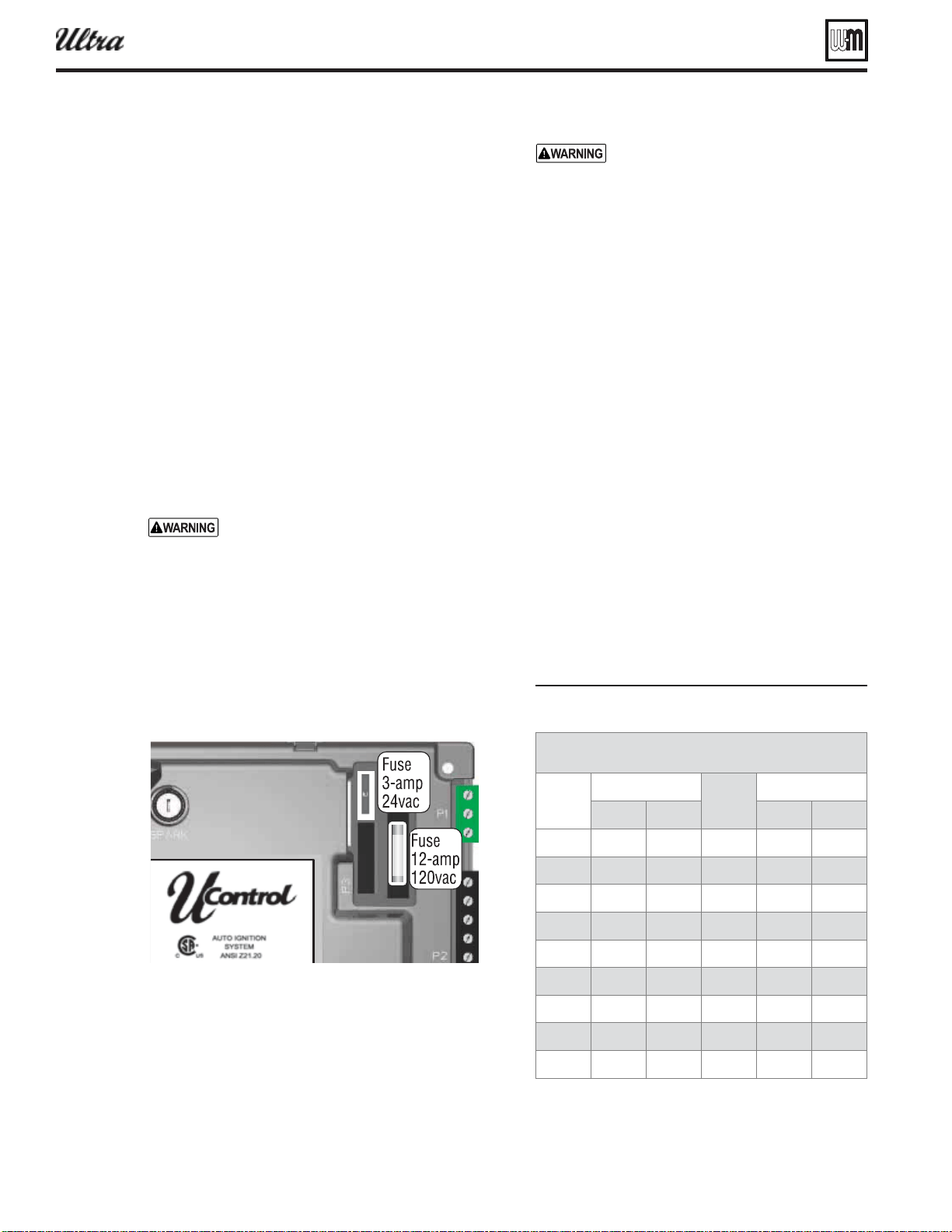
Part number 550-100-400/0119
116
Troubleshooting (continued)
Check the following:
1. Make sure thermostat is calling for heat and con-
tacts (including appropriate zone controls) are
closed. Check for 24 VAC between thermostat wire
nuts and ground.
2. Make sure all external limit controls are either
installed (and closed) or temporarily jumpered
for testing.
3. Make sure that connectors to control module are
securely plugged in at module and originating
control.
4. Gas pressures:
Maximum: 13” w.c. with no fl ow (lockup) or
with boiler on
Minimum: 4” w.c. (for all except 5” for
-299/310) for natural gas, or 4” w.c. for propane,
with gas fl owing (verify during startup with
boiler at high fi re)
Always check control module fuses
ALWAYS check control module fuses
before replacing control module or any
major components (blower, etc.). If one
of these fuses is blown, it can prevent
control module or other components
from operating.
1. Turn OFF power to boiler at external line switch.
2. Remove jacket door and jacket top panel. Rotate
the swing-away control panel forward to expose
the U-Control module.
3. Remove and inspect the two fuses (located as shown
below).
4. If necessary, replace the fuse:
a. Low voltage circuit fuse is 3-amp fast-blow
(Littelfuse 257003).
b. Line voltage circuit fuse is 12-amp slow-blow
(Littelfuse 326012P).
Do not jumper fuse or replace with any
fuse except as specifi ed. Failure to comply
could result in severe personal injury,
death or substantial property damage.
5. Reinstall jacket top panel and boiler jacket door
after checking the fuses.
6. Restore power to boiler at external line switch and
verify boiler operation after completing boiler
service.
Checking temperature sensors
1. The boiler temperature sensors (flue, outdoor,
return water and supply water) are all resistance-
type devices.
2. Figure 123 shows the correct value for the sensor
at various temperatures.
3. Use the resistance values at 32°F, 60°F, 70°F and
212°F to measure the sensor resistance at known
temperatures (ice point, room temperature and sea
level boiling point). For ice point and boiling point,
insert the sensor in water at that temperature. Use
an ohmmeter to read resistance value.
4. To check whether the control module is correctly
sensing temperature, you can use a resistance de-
cade box. Connect the decade box temporarily in
place of a sensor and read the corresponding tem-
perature on the U-Control display. The temperature
should be close to the value corresponding to the
input resistance.
Figure 123 Sensor resistance alues
®
Series 4
gas-fired water boiler — Boiler Manual
Sensor resistance values
Temp
(°F)
Sensor ohms
Temp
(°F)
Sensor ohms
Min Max Min Max
34265 37871
4517 4992
27834 30764
3698 4088
21630 23907
3043 3364
16944 18727
2517 2782
13372 14780
2091 2311
10629 11747
1744 1928
8504 9399
1461 1615
6847 7568
1229 1359
5545 6129
1038 1147
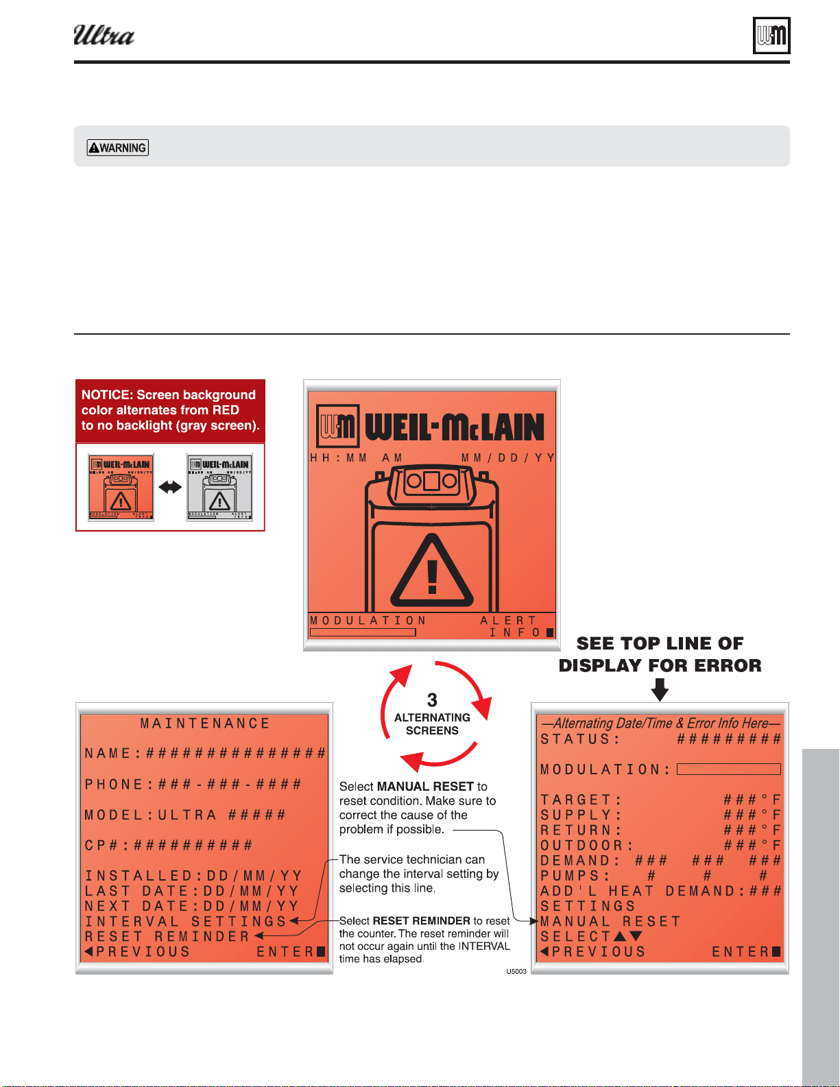
Part number 550-100-400/0119
117
Figure 124 U-Control displa toles hen in locout ith screen ashin red to ra
Troubleshooting (continued)
U-Control fault indications
1. The U-Control provides diagnostic information for
both automatic reset conditions and manual reset
conditions. See Figure 117, page 106 for informa-
tion available on the U-Control display.
2. Figure 124 shows the screen behavior during an
automatic or manual reset condition. The table
below the display illustration lists manual reset conditions and how
to reset from them.
3. Figure 125, page 118 lists conditions that will cause the control to dis-
play a constant red screen. The boiler will automatically restart if the
condition self-corrects or the technician uses the U-Control’s manual
reset screens to reset.
Make sure to determine the causes of outages. Do not leave the boiler operating without a complete diagnosis.
®
Series 4
gas-fired water boiler — Boiler Manual
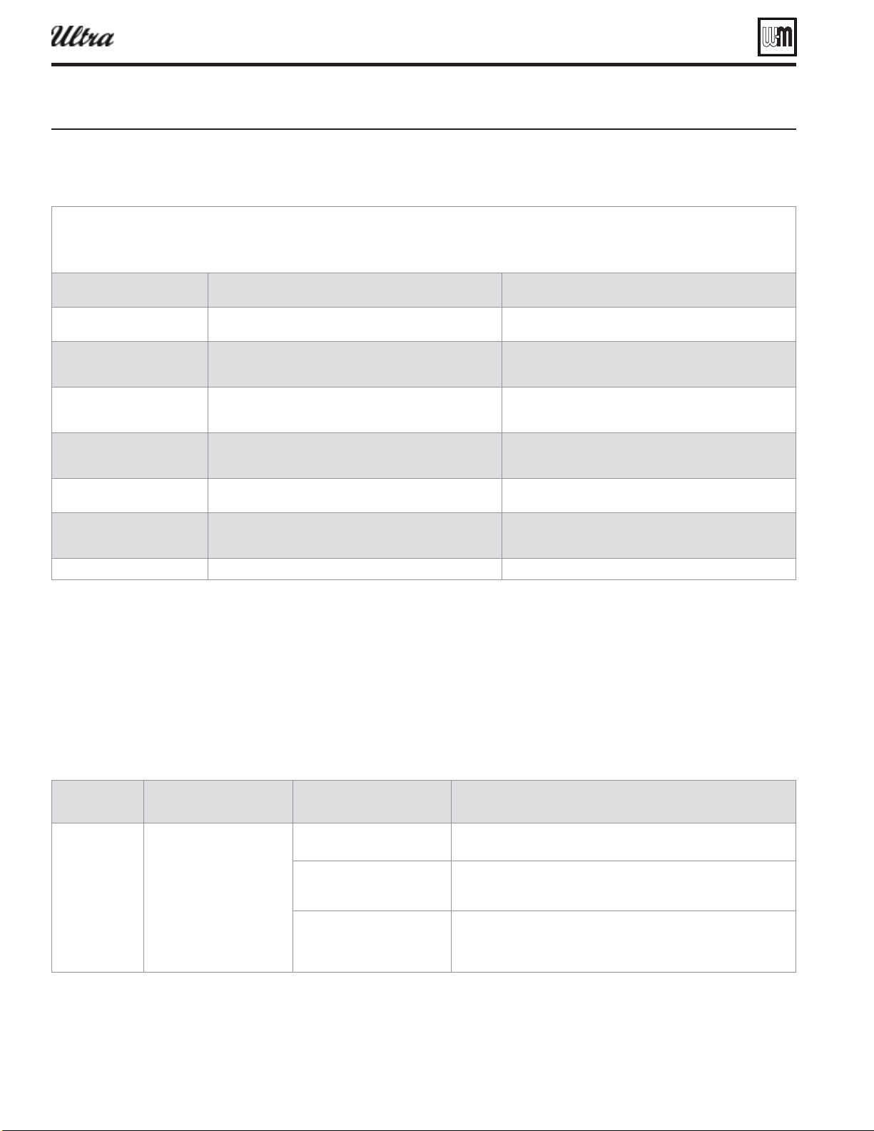
Part number 550-100-400/0119
118
Troubleshooting (continued)
Figure 125 Trouleshootin suestions for Ultra oilers
U-Control Fault Displays, Diagnostics and Suggested Corrective Actions
Display
Condition Diagnostics Corrective Action(s)
Nothing shown
on display
screen and
blower running
at full speed
Control is not receiving 24V
power
Check wiring for short circuit or
incorrect wiring.
Correct wiring per wiring diagram including connection of transformer
to the U-Control.
Check 3-amp low voltage fuse
on U-Control shown on page
100.
Replace fuse with proper part found in replacement part section of this
manual. If fuse blows again recheck wiring per diagram.
Check transformer connection
to the U-control per wiring
diagram. Check for 24V output
of transformer.
Replace transformer if it is receiving 120VAC, but not outputting 24VAC.
U-Control Error Condition Log
The U-control is able to record information about the boiler’s condition at the time of the three previous faults or errors. This
information is available to view in Contractor Menus under “DIAGNOSTICS” by selecting “ERRORS.” The control will display
the following information:
*OGPSNBUJPO%FTDSJQUJPO"DUJPO
$POUSPM'BVMURecords the number of internal control faults Select and press the enter key to reset this count
*HOJUJPO3FUSJFTDisplays the number of ignition attempts in the current
ignition sequence.
.BOVBM3FTFU$PVOURecords number of lockouts that required a manual reset
since this count was last cleared.
Select and press the enter key to reset this count
"VUP3FTFU$PVOURecords number of lockouts that have automatically reset
since this count was last cleared.
Select and press the enter key to reset this count
-PDLPVU)JTUPSZDetails of present or last recorded lockout Select and press the enter key for more details
-PDLPVU)JTUPSZDetails of boiler during the second oldest lockout still in
memory
Select and press the enter key for more details
-PDLPVU)JTUPSZDetails of boiler during the oldest lockout still in memory Select and press the enter key for more details
)PXUPSFBEUIFMBTUMPDLPVUIJTUPSJFT
1. Scroll down to “DIAGNOSTICS” and press the
enter key (Square Key in center)
2. Scroll down to “ERRORS” and press the enter key
(Square Key in center)
3. Scroll down to “LOCKOUT HISTORY #” and press
the enter key.
4. Scroll to choose the either “MANUAL RESET” or
“AUTO RESET” and press the enter key to display
the fault condition that was recorded.
5. Press the left arrow key to return to the LOCKOUT
HISTORY # screen. Scroll up or down to highlight
other choices and press the enter key to view the
details of the boiler’s condition when the lockout
was recorded.
6. TO CLEAR ALL LOCKOUT HISTORIES: While on the
“ERRORS” screen, hold the Left and Right arrow
buttons simultaneously for 5 seconds.
®
Series 4
gas-fired water boiler — Boiler Manual
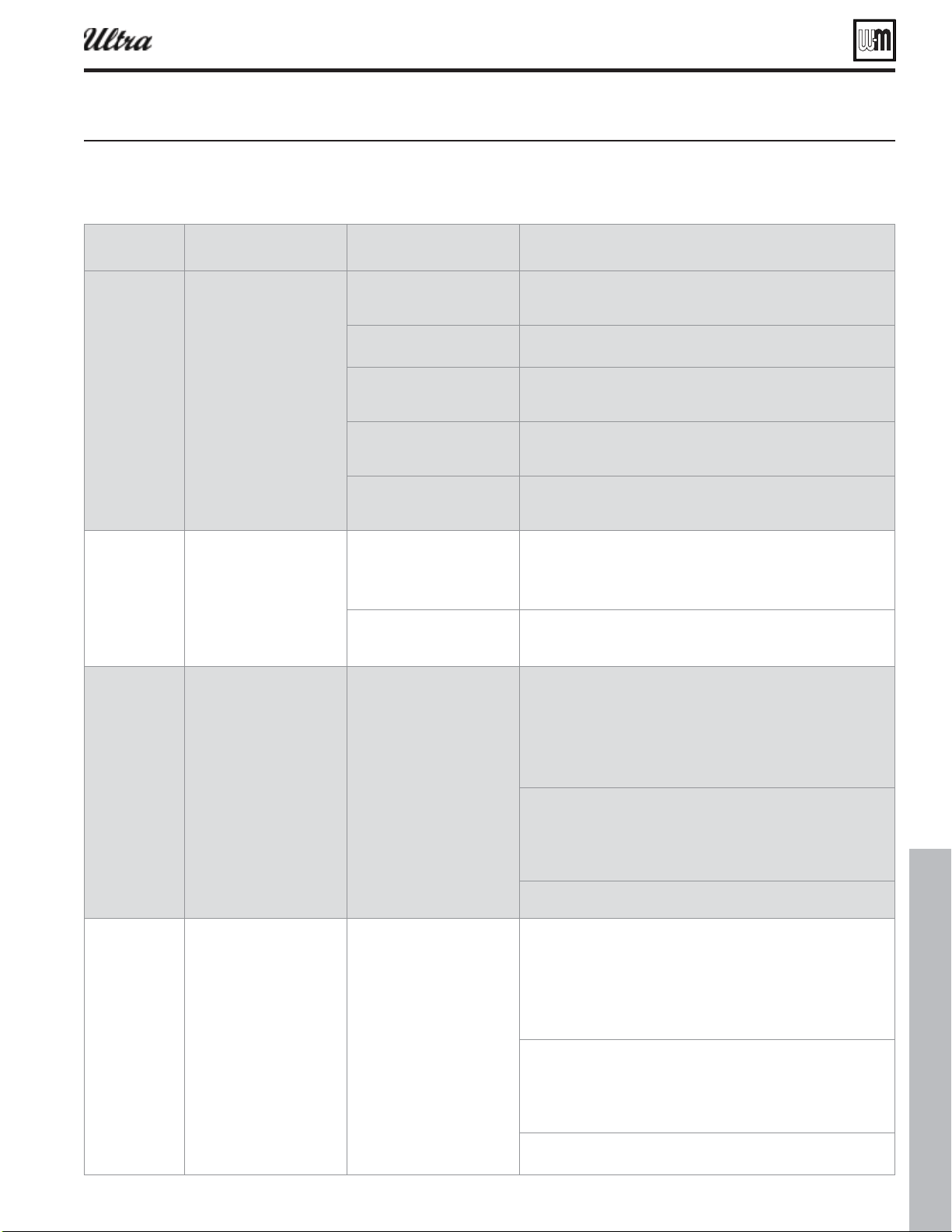
Part number 550-100-400/0119
119
Troubleshooting (continued)
Display
Condition Diagnostics Corrective Action(s)
Nothing
is shown
in display
screen and no
other boiler
components are
operating
Control is not receiving 120V
power.
Check service switch and/or
circuit breaker to boiler turned
is on.
Turn on service switch to power boiler.
Is there 120 Volts at the service
switch?
Troubleshoot and correct the power supply to the service switch.
Is the Ultra's ON/OFF POWER
SWITCH located behind the
control pod turned on?
Turn the Ultra's power switch behind the control pod to ON.
Check for 120 volts at the line
voltage terminal block located
inside the control pod.
Correct wiring inside the control pod using the wiring diagram in this
manual.
Inspect 12-amp fuse as shown
on page 100. Replace if
necessary.
Replace the fuse with proper part found in the replacement part section
of this manual. If fuse blows again recheck wiring per diagram.
Nothing is
shown on
display screen,
but boiler is
operating
Occurs when the
communication is lost from
the U-control to the display.
Check for loose connections
and proper pin alignment/
engagement on the U-Control's
plug P9 and the back of the
display circuit board.
Check for continuity on the wire harness from the display to the
U-control. See repair parts section for proper replacement part.
Cycle power off and on using
boiler power switch and check
for operation.
Replace with new display module. See repair parts section for proper
replacement part.
5&.13*4&500
QUICKLY
Occurs when supply
water temperature in heat
exchanger rises faster than
2ºF per second during the
fi rst two minutes the burner
is on.
Automatically resets after 1
minute delay or using manual
reset on display.
Manual reset is necessary after 5
automatic resets have occurred
during the same Priority heat
demand. Reset using manual
reset screen on display.
Verify water pipe is installed correctly using primary/secondary
connection to the boiler loop. Refer to Figure 4 page 11 for example of
primary/secondary connection.
Minimum pipe sizes
Ultra 80/105 - minimum 1 inch
Ultra 155/230 - minimum 1.25 inch
Ultra 299/310/399 - minimum 1.5 inch
Verify proper circulator sizing for boiler size and system requirements
starting on page 9.
Boiler ship with proper size circulators:
Ultra 80/105 - Taco 007e ECM
Ultra 155/230/299/310 - Taco 0014
Ultra 399 - Taco 0013
See message displayed TEMPERATURE SENSOR and follow procedure for
loose connections.
4611-:'
3&563/
Boiler Out temperature
has exceeded the Boiler In
temperature by more than
58ºF, when burner is on.
Automatically resets after 30
second delay or using manual
reset on display.
Verify water pipe is installed correctly using primary/secondary
connection to the boiler loop. Refer to Figure 4 page 11 for example of
primary/secondary connection.
Minimum pipe sizes
Ultra 80/105 - minimum 1 inch
Ultra 155/230 - minimum 1.25 inch
Ultra 299/310/399 - minimum 1.5 inch
Verify proper circulator sizing for boiler size and system requirements
starting on page 9.
Boiler ship with proper size circulators:
Ultra 80/105 -Taco 007e ECM
Ultra 155/230/299/310 - Taco 0014
Ultra 399 - Taco 0013
See message displayed TEMPERATURE SENSOR and follow procedure for
loose connections.
iure Trouleshootin suestions for Ultra oilers (continued)
®
Series 4
gas-fired water boiler — Boiler Manual
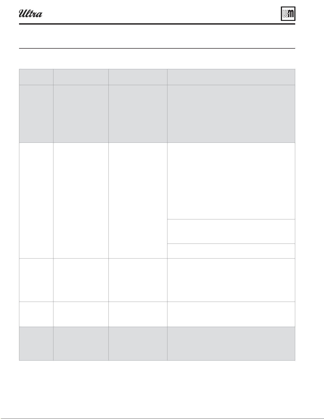
Part number 550-100-400/0119
120
Troubleshooting (continued)
Display
Condition Diagnostics Corrective Action(s)
3&563/
4611-:
Occurs when a return water
temperature is greater than
the corresponding supply
temperature by 10ºF or more.
Applies to system sensors or
boiler sensors.
Condition must occur for 10
minutes for system sensors.
Automatically resets when
condition no longer exists.
Verify proper fl ow direction of the boiler circulator. This circulator should
be installed to push water through the boiler's return pipe as shown in
Figure 4 on page 11.
Verify proper placement of system sensors for single or multiple boiler
systems. System sensors should be on system piping not on the boiler
loop.
System sensors may need located further away from boiler loop
connection to the system if proximity to the boiler loop is causing
sensors to be heated inaccurately.
5&.1&3"563&
4&/403
Occurs when a temperature
sensor has electrically shorted
(SHORT) or has become
disconnected (OPEN).
Automatically resets when
condition no longer exists.
Check all the temperature readings of the boiler on the DIAGNOSTICS -
TEMPERATURES menu to determine if any sensors are currently displayed
as SHORT or OPEN. Compare this to the boiler temperatures recorded
in the DIAGNOSTICS - ERRORS - LOCKOUT HISTORY # - TEMPERATURES
during the last several lockout conditions.
Determine which sensors are suspect and measure their resistance
value and compare it to the values shown in Figure 109. If the resistance
values are incorrect replace the temperature sensor. Refer to repair parts
section for proper part number.
OUTDOOR TEMP, SYSTEM SUPPLY, and SYSTEM RETURN are the optional
outdoor air temperature and system water temperature sensors. If these
are not being used they will always be shown as OPEN. This is normal
unless the sensors were installed.
Check wire harness for loose connections and pin engagement at sensor
connection, chassis mount connection through sheet metal cabinet, and
U-Control module. Unplug connection at sensor and at U-Control and
check continuity between ends.
If problem persists after checking items above replace U-Control. Refer
to repair parts section for kit number.
'-6&5&.1
500)*()
Occurs when fl ue
temperature sensor exceeds
216ºF.
Automatic reset occurs if
temperature drops below 216ºF
for 2.5 min.
Manual reset is required if the
temperature rises above 225°F.
Reset using manual reset screen
on display.
Follow procedure for above for SHORT and OPEN sensor conditions
to properly diagnose sensor. In addition inspect heat exchanger
combustion chamber and fl ueways for abnormal wear or buildup.
Inspect vent system for abnormal wear or damage.
Contact Weil-McLain Technical Support.
5&.1&3"563&
4&/403
Occurs when dual
temperature sensors values
have spread by more that
10ºF.
Automatically resets when
sensors are within 10ºF.
Follow procedure for above for SHORT and OPEN sensor conditions
to properly diagnose sensor. If measured resistance values of sensors
convert to temperatures separated by more than 10ºF replace the sensor.
-08853
$650''01&/
Occurs when Low Water
Cutoff Device contacts open
for more than 1 second.
Requires manual reset of
U-Control and may require
manual reset of LWCO device
depending on model.
Check for low water condition in system. Repair system as necessary
refer to piping section of this manual.
If low water condition does not exist check Diagnostics - Inputs screen to
view status of Low Water Cutoff . If shown as OPEN check wiring between
LWCO and U-Control.
Troubleshooting (continued)
®
Series 4
gas-fired water boiler — Boiler Manual
iure Trouleshootin suestions for Ultra oilers (continued)
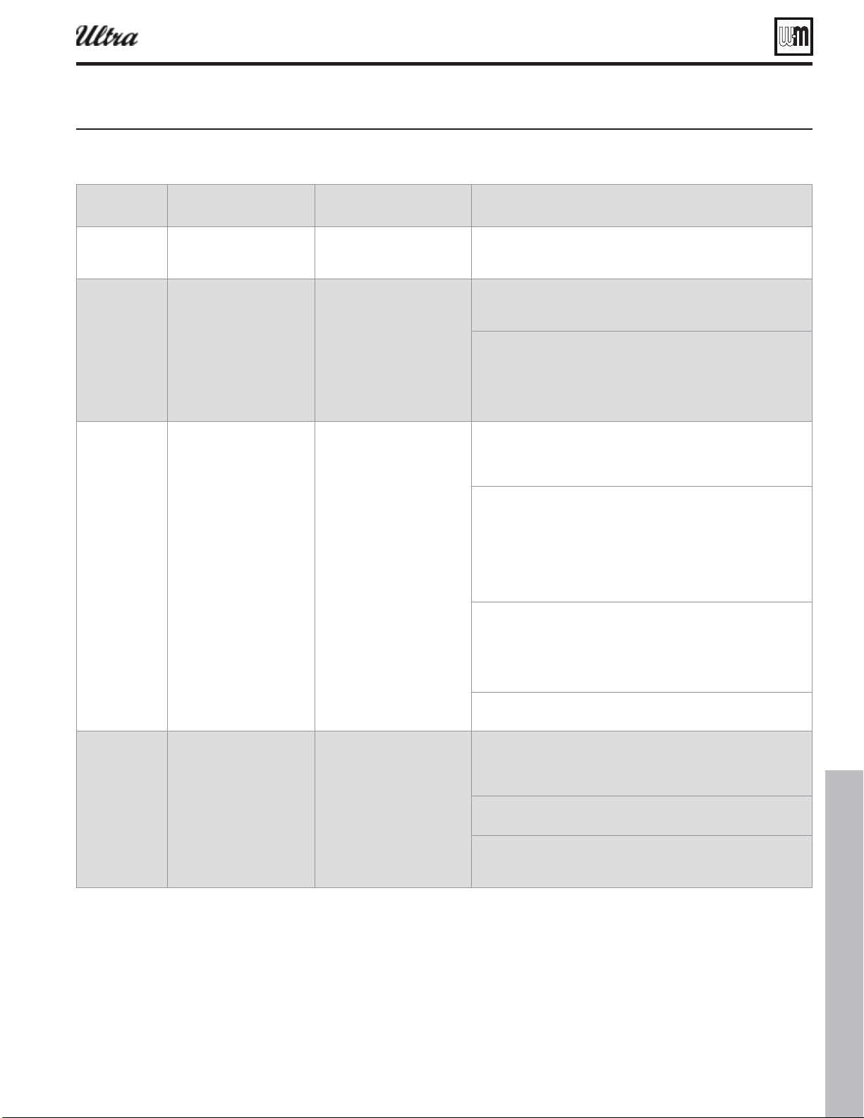
Part number 550-100-400/0119
121
Troubleshooting (continued)
Display
Condition Diagnostics Corrective Action(s)
%*41-":$0..
Occurs when display
communications out for 30
seconds.
Automatically resets when
communication is re-
established.
Check for a loose connection at the molex plug on the control and
connection on the back of the display.
-*.*501&/
Occurs when manual or
automatic reset limit opens.
Automatic external limit will
reset 2.5 minutes after external
limit device closes.
Manual limit fault must be reset
by choosing Reset Lockout on
the display.
Is there an external safety device connected? If yes, trouble shoot the
external limit to determine and correct the cause that opened the limit.
Also check for loose wiring connections.
Remove the top front cover and inspect the ORANGE - 4 PIN connector
P13.
Ensure a jumper is installed between pins 1 & 2 if not using a manual
reset external limit.
Ensure a jumper is installed between pins 3 & 4 if not using a automatic
reset external limit.
)*()5&.1
-*.*5
Boiler temperature sensor
reached High Temp Limit
setting (no higher than 200°F).
Reset using manual reset screen
on display.
Verify all isolation valves are open and circulators are programmed into
the U-Control properly. Each Priority input can be confi gured to turn
on any combination of three circulator outputs. Refer to the U-Control
Setup section to confi gure these properly for the system.
Verify water pipe is installed correctly using primary/secondary
connection to the boiler loop. Refer to Figure 4 page 11 for example of
primary/secondary connection.
Minimum pipe sizes
Ultra 80/105 - minimum 1 inch
Ultra 155/230 - minimum 1.25 inch
Ultra 299/310/399 - minimum 1.5 inch
Verify proper circulator sizing for boiler size and system requirements
starting on page 9.
Boiler ship with proper size circulators:
Ultra 80/105 - Taco 007e ECM
Ultra 155/230/299/310 - Taco 0014
Ultra 399 - Taco 0013
See message displayed TEMPERATURE SENSOR and follow procedure for
loose connections.
'-".&'"6-5
Occurs when fl ame is
detected when there should
be no fl ame.
Reset using manual reset screen
on display.
Burner may be operating too hot due to incorrect combustion. Inspect
fl ame and conduct combustion test.
Force boiler into hi-fi re. Check fl ue gases with combustion analyzer and
correct using the maintenance and startup procedure in this manual.
Verify FLAME SIGNAL value quickly goes to zero on the DIAGNOSTICS -
INPUTS screen when the gas valve closes.
Check for fl ame at burner via fl ame current with burner off . Turn boiler
off and watch fl ame through observation port. If fl ame continues after
shutdown replace gas valve and venturi.
Troubleshooting (continued)
®
Series 4
gas-fired water boiler — Boiler Manual
iure Trouleshootin suestions for Ultra oilers (continued)
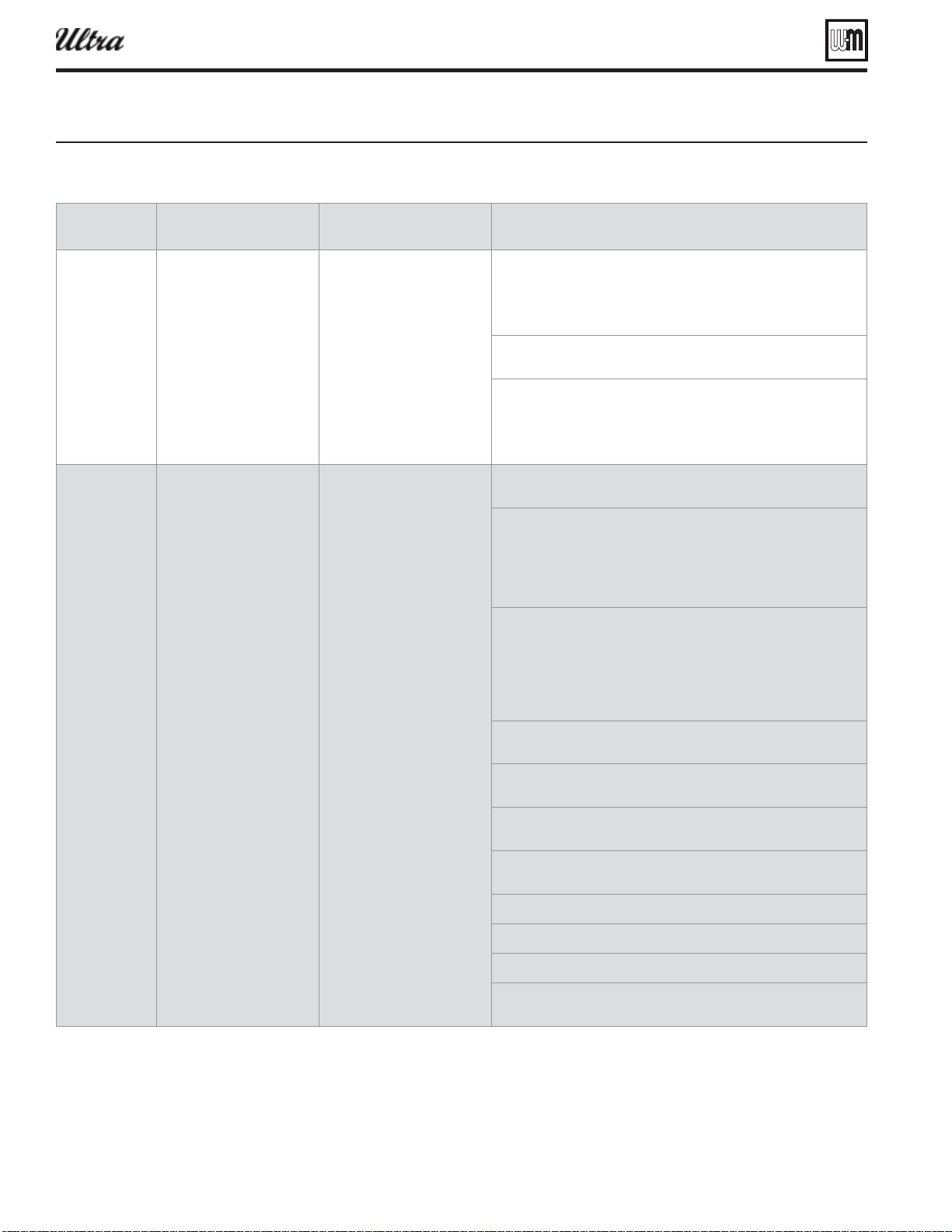
Part number 550-100-400/0119
122
Display
Condition Diagnostics Corrective Action(s)
#-08&3'"6-5
Blower unable to reach
required speed or does not
reach 0 RPM when turned off .
Automatically resets after 1 hour
or can be reset by using manual
reset on screen.
Check wire harness for loose connections and pin engagement at blower
connections, chassis mount connection through sheet metal cabinet,
and U-Control module. Unplug connection at sensor and at U-Control
and check continuity between ends. Blower is connected to both low
voltage and line voltage harness.
Check Diagnostics - Inputs screen with boiler in standby mode and
blower not running. If BLOWER SPEED is not 0 RPM then replace blower.
If blower does not rotate during ignition sequence check for 120V power
at blower connection. If 120Vac power at blower motor and it doesn't
start replace blower. Check power at U-Control. If 120Vac is not present
at U-Control when boiler is powered replace U-Control. Refer to repair
parts section.
*(/*5*0/
'"6-5
Boiler went through 5 ignition
attempts and never detected
fl ame.
Automatically resets after 1 hour
or can be reset by using manual
reset on screen.
Check condensate trap for blockage allowing condensate to accumulate
inside heat exchanger
Fouled, worn, bent, or faulty igniter.
Fouled igniters can be cleaned for additional use with fi ne grit sand
paper or steel wool.
Worn or badly fouled igniters should be replaced with the proper repair
part.
Igniter rods should be parallel with a 3.5mm (0.138 in) spark gap.
Dirty burner and/or heat exchanger will cause high back pressure and
poor ignition. Follow procedure in maintenance section of this manual
to clean burner and heat exchanger using fl ue cleaning tool and rinse
method.
Visual inspection of fl ueways will often will not be able to diagnose
condition.
Check combustion settings on high and low fi re and adjust per setup
instructions if necessary.
Check incoming gas pressure with boiler off and at high fi re. Adjust
within limits on rating label.
Verify correct boiler model is selected in control and high altitude is
selected for installations 5500 ft above sea level.
Check ignition cable resistance. Should measure 1000 Ohms (+/- 50
Ohms)
Check for fl ue pipe and intake pipe restrictions or blockage
Check burner fasteners and gaskets
Check venturi gaskets and proper propane orifi ce
Check condensate trap for blockage allowing condensate to accumulate
inside heat exchanger
Troubleshooting (continued)
®
Series 4
gas-fired water boiler — Boiler Manual
iure Trouleshootin suestions for Ultra oilers (continued)
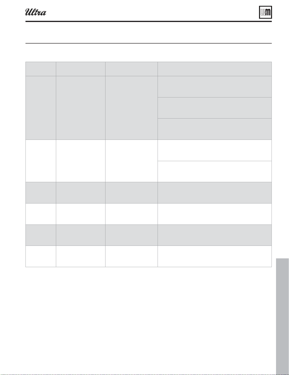
Part number 550-100-400/0119
123
Display
Condition Diagnostics Corrective Action(s)
("47"-7&
'"6-5
The U-Control has detected
a problem with it gas valve
output circuit
Automatic retry when condition
exists. Boiler will reset if
conditions clears. If condition
does not clear boiler will retry in
1 hour. If condition is not clear
after 1 hour, boiler will require
manual reset.
Check wire harness connections between gas valve and U-Control.
Check resistance between
If lockout reoccurs replace U-Control.
"*313&4463&
48'"6-5
Air Pressure switch is open Ultra residential boilers do not
use an air pressure switch, but
instead have a wire jumper
installed between P7 pins 4 & 5.
Reset using manual reset screen
on display
Check boiler size selected in U-Control against boiler rating label. Correct
if necessary to select the proper boiler size.
Check the P7 connection as seen on Figures 98 & 99 to determine proper
jumper wire location.
("413&4463&
48'"6-5
Gas pressure switch is open
(high or low)
Residential Ultra Boilers do
not use gas pressure switches.
Requires manual reset.
Check boiler size selected in U-Control against boiler rating label. Correct
if necessary to select the proper boiler size.
)8'"6-5
&91"/4*0/
#3%
Expansion Control Board
hardware has failed.
Residential Ultra Boilers do not
use an Expansion Control Board.
Requires manual reset.
Check boiler size selected in U-Control against boiler rating label. Correct
if necessary to select the proper boiler size.
(7'"6-5
&91"/4*0/
#3%
Gas valve output of the
Expansion Board
Residential Ultra Boilers do not
use an Expansion Control Board.
Requires manual reset.
Check boiler size selected in U-Control against boiler rating label. Correct
if necessary to select the proper boiler size.
&91#0"3%
$0.'"6-5
Communication between the
Expansion Control Board and
the U-Control Board has failed
Residential Ultra Boilers do not
use an Expansion Control Board.
Requires manual reset.
Check boiler size selected in U-Control against boiler rating label. Correct
if necessary to select the proper boiler size.
Troubleshooting (continued)
®
Series 4
gas-fired water boiler — Boiler Manual
iure Trouleshootin suestions for Ultra oilers (continued)
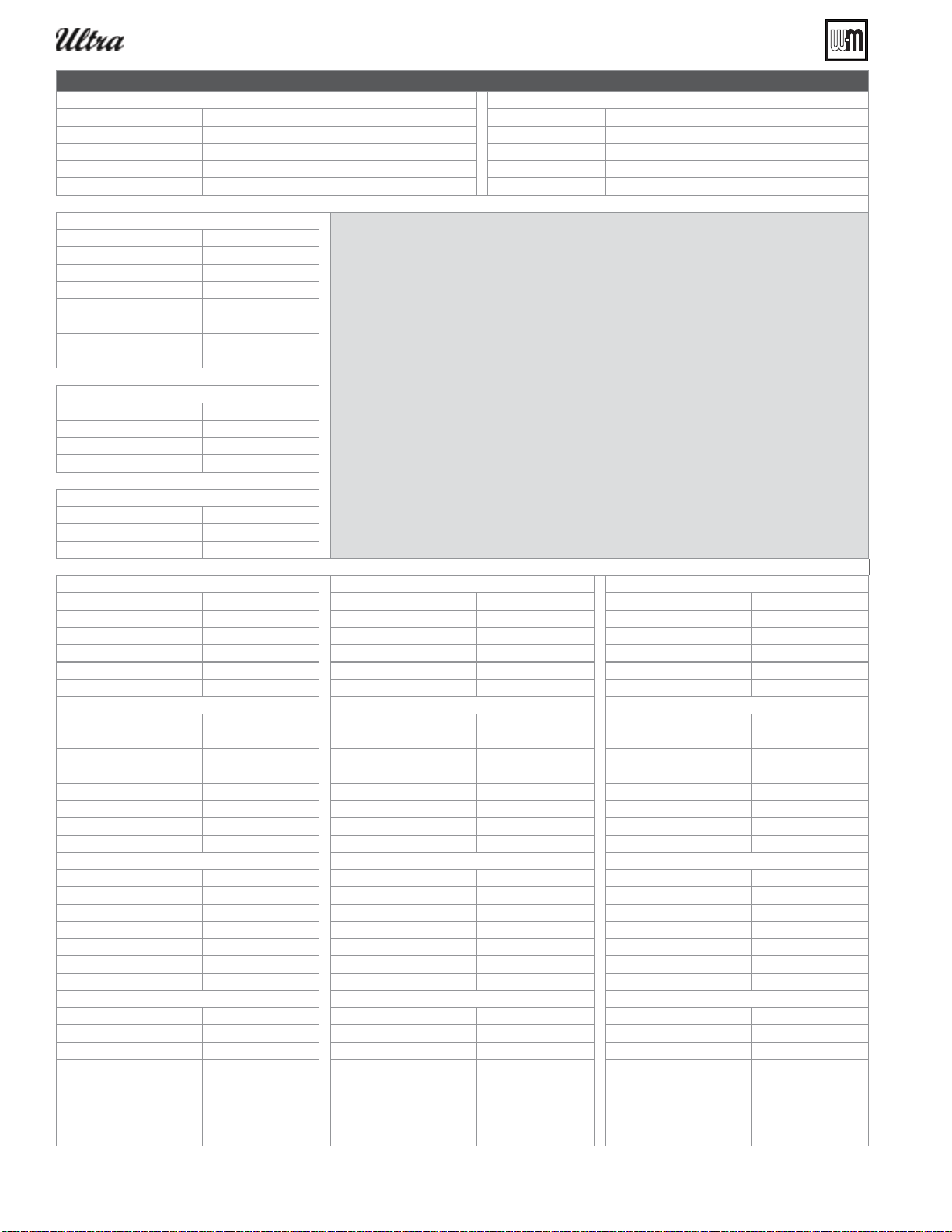
Part number 550-100-400/0119
124
Contact Name
Contractor hone
o name odel
Cit state C
istriutor Installed
Near boiler pipe size:
lease note the placement of sstem sensors
Boiler circulator model:
DHW tank (yes/no):
DHW direct/system:
Dhw model:
Dhw pipe size:
DHW circulator model:
Is there air in system?:
Control fault
Inition retries
anual reset CNT
Auto reset CNT
ispla
ain micro
Second micro
Status Status Status
anual reset anual reset anual reset
If es-description If es-description If es-description
Auto reset Auto reset Auto reset
If es-description If es-description If es-description
riorit riorit riorit
riorit riorit riorit
riorit riorit riorit
anual limit anual limit anual limit
Auto limit Auto limit Auto limit
Lo T Cutoff Lo T Cutoff Lo T Cutoff
Bloer tach Bloer tach Bloer tach
lame Sinal lame Sinal lame Sinal
as ale as ale as ale
Circulator Circulator Circulator
Circulator Circulator Circulator
Circulator Circulator Circulator
Bloer sinal Bloer sinal Bloer sinal
Additional heat demand: Additional heat demand: Additional heat demand:
Alarm Alarm Alarm
Sstem suppl Sstem suppl Sstem suppl
Sstem return Sstem return Sstem return
Boiler out Boiler out Boiler out
Boiler out Boiler out Boiler out
Boiler in Boiler in Boiler in
lue lue lue
lue lue lue
Outdoor Outdoor Outdoor
®
Series 4
gas-fired water boiler — Boiler Manual
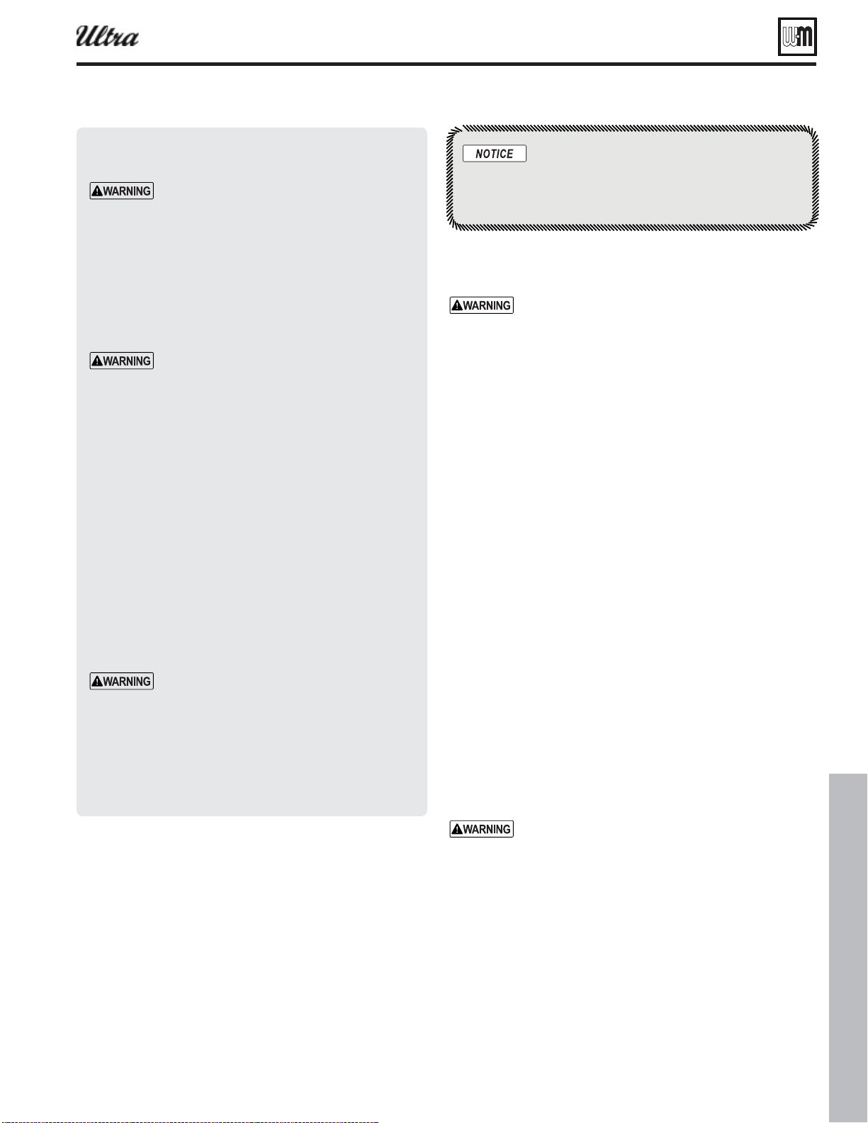
Part number 550-100-400/0119
125
Cleaning the hea t exch anger — pin side
when required
The boiler contains ceramic fi ber materials. Use care
when handling these materials per instructions on
page 109 of this manual. Failure to comply could
result in severe personal injury.
1. Shut down boiler:
a. Follow “To Turn Off Gas to Appliance” instructions on
boiler and Lighting instructions.
b. Do not drain boiler unless it will be exposed to freezing
temperatures. If using freeze prevention fl uid in system,
do not drain.
2. Allow time for boiler to cool to room temperature if it has
been fi ring.
3. Remove jacket front door by removing two (2) screws at lower
front. Lift door away from boiler to remove.
4. Follow the applicable procedures under
heat exchanger: Ultra-80 and Ultra-105 Only,” page 126 or
and -399 Only,” page 127 .
Clean the c ast aluminum heat exchanger
when required — water side
1. In order for the effi ciency of boilers to increase beyond the
condensing limit, new materials have been introduced for the
heat exchanger, including aluminum.
2. Aluminum has excellent heat transfer characteristics and is
light in weight.
3. These new materials also require cleaning solutions that differ
from those used in conventional cast iron and steel boilers.
One common cleaning method that be
used with systems containing aluminum is a solu-
tion of trisodium phosphate, commonly referred to
as “TSP.”
The reason that trisodium phosphate cannot be
used is that the cleaning solution has a very high pH
level — while removing the scale in the system, it
also removes the natural protective oxide layer from
the aluminum. The oxide layer will reform, but if
small amounts of the trisodium phosphate remain
in the system, the chemical will continue to remove
the protective oxide layer, leading to reduced heat
exchanger life.
4. Use ONLY the cleaning product available from Weil-McLain,
Sentinel X400. See the Repair Parts section at the end of this
manual for ordering information.
General maintenance
1. Oil motor in system requiring regular oiling.
2. See Oiled bearing circulators for motor oiling procedures.
Oiled bearing circulators
1. The circulator shipped with the Ultra boiler is water-lubri-
cated. No oiling is required.
2. Check other circulators in the system. Oil any circulators
requiring oil, following circulator manufacturer’s instruc-
tions. Over-oiling will damage the circulator.
Disconnect power
Electrical shock hazard — Disconnect all elec-
trical power to the boiler before attempting
maintenance procedures. Failure to complete
could result in severe personal injury, death
or substantial property damage.
Install boiler j acket front door after
startup or servicing
Reinstall boiler jacket front door after start-
up or servicing. The boiler front door must
be securely fastened to the boiler to prevent
boiler from drawing air from inside the boiler
room. This is particularly important if the
boiler is located in the same room as other
appliances.
Inspect boiler jacket door gaskets. Gaskets
must be in good condition, with no tears or
gaps. Replace if necessary.
Failure to keep the door securely sealed and
fastened could result in severe personal injury
or death.
Perform start-up and check/out
Removing and reinstalling components can
change boiler behavior. After any mainte-
nance procedure, you must prove the boiler
is operating correctly. To do so, follow the
complete procedure for boiler and system
start-up, beginning on page 35 . Failure to
comply could result in severe personal injury,
death or substantial property damage.
Maintenance
Attention to homeowners and installers
of Ultra Series 4 boilers– see page 126
for the latest cleaning information for
our newly coated heat exchangers.
®
Series 4
gas-fired water boiler — Boiler Manual
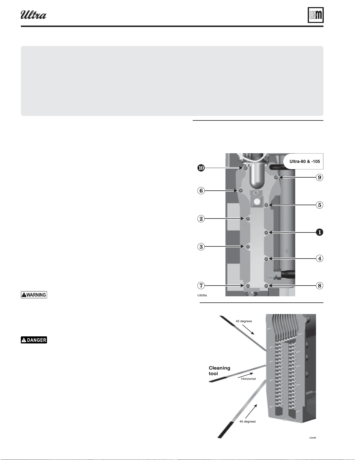
Part number 550-100-400/0119
126
Maintenance (continued)
Figure 126
For the fi rst 5 years, vacuum or rinse heat exchanger with water only.
No tool cleaning is necessary.
Figure 127
®
Series 4
gas-fired water boiler — Boiler Manual
Accessing & cleaning heat exchanger:
Ultra-80 and Ultra-105 Only
1. Close the external manual gas valve.
2. Disconnect the fl exible gas line at its fl are fi tting.
3. Remove the air silencer by separating it from the air adapter on the
blower inlet.
4.
5. Release the heat exchanger cover plate by removing the nuts securing
it to the exchanger.
6. Pull the entire blower/venturi/gas valve/cover plate assembly out of the
boiler. (See Replacement parts section for component identifi cation
and locations.)
7. Use a vacuum cleaner to remove any accumulation on the heating
surfaces. Do not use any solvent.
8. If the vacuum cleaner is unable to clean completely, wash the heating
surfaces with clean, warm water. If further cleaning is necessary, use
the Heat Exchanger Cleaning Tool (see Replacement parts at the end
of this manual) or a piece of 20-gauge or lighter sheet metal ¾” wide
by about 18 inches long to loosen deposits. See Figure 127 .
.
9. Inspect the heat exchanger cover plate insulation. Replace if insulation
is damaged. Read the ceramic fi ber WARNING on page 109 before
handling or disposing of ceramic fi ber materials.
10. Reinstall the blower/venturi/gas valve/cover plate assembly and secure
the cover plate with nuts.
You must gradually tighten the cover plate nuts. For Ultra-80
and -105, follow the tightening sequence shown in Figure 126 ,
making two or three passes with a torque wrench. The fi nal
torque MUST NOT exceed 50 inch-pounds, +/- 10 inch-
pounds.
11.
If the valve adapter block is removed, carefully inspect the
O-ring that should still be in the gas valve inlet adapter block.
The O-ring must be in good condition and must be installed
when gas valve is reconnected. Failure to comply will cause a
gas leak, resulting in severe personal injury or death.
12. Reconnect the fl exible gas line.
13. Reinstall the air silencer by pressing onto the air inlet adapter.
14. Perform a soap suds leak test on all interior gas piping after starting
the boiler.
Cleaning the hea t exchanger — water side (ALL
models)
1. Follow the procedure given in “Clean the cast aluminum heat exchanger
when required — water side,” page 125 to clean the water side of the
exchanger.
2. Follow the complete procedure for boiler and system start-up, begin-
ning on page 35 .
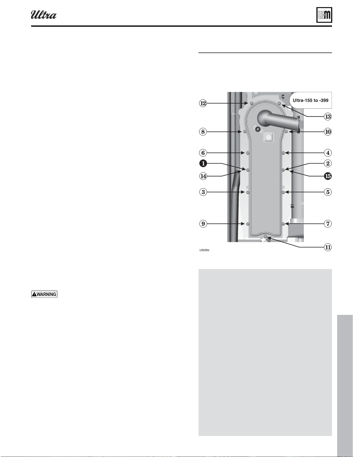
Part number 550-100-400/0119
127
Maintenance (continued)
Accessing & c leaning exchanger: Ultra-155,
-230, -299/310 and -399 Only
1. Close the external manual gas valve.
2.
3. Disconnect the fl exible gas line at its fl are fi tting.
4. Remove the air silencer by lifting the plastic clamp off of the gas
line and then gently sliding the air silencer down and off the valve.
5. Remove hex head nuts (10mm box end wrench) from heat exchang-
er cover plate and remove burner cover plate from heat exchanger.
6. Pull the entire blower/venturi/gas valve/cover plate assembly out
of the boiler. (See Replacement parts section for component iden-
tifi cation and locations.)
7. Remov e three (3) M4 hex head screws (7mm box end wrench) and
burner clips securing burner to cover plate. Remove cover plate.
8. Use a vacuum cleaner to remove any accumulation on the heating
surfaces. Do not use any solvent.
9. If the vacuum cleaner is unable to clean completely, wash the
heating surfaces with clean, warm water. If further cleaning is
necessary, use the Heat Exchanger Cleaning Tool (see Replacement
parts at the end of this manual) or a piece of 20-gauge or lighter
sheet metal ¾” wide by about 18 inches long to loosen deposits.
See Figure 127, page 126 .
10. Inspect the heat exchanger cover plate insulation and gasket. Re-
place if damaged. Read the ceramic fi ber WARNING on page 109
before handling or disposing of ceramic fi ber materials.
11. Replace the burner, hex head screws and burner clips removed in
step 7. See Figure 120, page 112 .
12. Place cover plate gasket in groove of heat exchanger cover plate.
Replace cover plate.
13. Reinstall hex head nuts on the cover plate mounting studs and
tighten in a staggering pattern until cover plate is uniformly
tightened.
You must gradually tighten the cover plate nuts. For
Ultra-155 through -399, follow the tightening sequence
shown in Figure 128 , making two or three passes with
a torque wrench. The fi nal torque MUST NOT exceed
50 inch-pounds, +/- 10 inch-pounds.
14. Reinstall air silencer by sliding on gas valve venturi and securing
clamp to gas line.
15.
16. Reconnect the fl exible gas line and gas valve electrical plug.
17. Perform a soap suds leak test on all interior gas piping after start-
ing the boiler.
Cleaning the hea t exchanger — water side (ALL
models)
1. Follow the procedure given in “Clean the cast aluminum heat ex-
changer when required — water side,” page 125 to clean the water
side of the exchanger.
2. Follow the complete procedure for boiler and system start-up,
beginning on page 35 .
Figure 128
WATER SPRAY HEAT EXCHANGER
PINS AFTER USING CLEANING TOOL
1. After using the cleaning tool as shown in Fig-
ure 127, page 126 , spray water downward from
above the pins to fl ush remaining sediment.
2. Remove sediment from the bottom of the heat
exchanger.
3. Then disconnect the condensate line at the bottom
of the heat exchanger.
a. Loosen the hose clamps at both ends of the
condensate line.
b. Remove the line and place a pan under the trap
connection.
c. Spray water into the bottom of the heat ex-
changer to fl ush remaining sediment to the
condensate outlet.
d. Spray water through the condensate line to
clean it thoroughly.
e. Remove pan and replace the condensate line.
f. Follow instructions on page 126 or page 127
to check components and replace burner and
cover.
®
Series 4
gas-fired water boiler — Boiler Manual
Part number 550-100-400/0119
128
Replacement parts
Replacement parts must be purchased through a local Weil-McLain distributor. When ordering,
specify boiler model and size and include description and part number of replacement part.
Results from using modifi ed or other manufactured parts will not be covered by warranty and
may damage boiler or impair operation.
Weil-McLain part numbers are found in Weil-McLain Boilers and Controls Repair Parts Lists.
. Use care when handling these materials per
instructions on page 109 of this manual. Failure to comply could result in severe personal injury.
Reinstall boiler jacket front door after startup or servicing
Inspect boiler jacket front door gaskets and reinstall boiler jacket front door after start or
servicing. The boiler front door must be securely fastened to the boiler to prevent boiler from
drawing air from inside the boiler room. This is particularly important if the boiler is located
in the same room as other appliances. Failure to keep the door securely fastened could result in
severe personal injury or death.
Figure 129 ropane conersion its and instructions
The conversion kits listed below are only for use with Ultra Series 4 boilers. For series 1 or series 2 boilers,
refer to the boiler manual or contact Weil-McLain for the correct parts.
SERIES 4 BOILERS ONLY
(not required for Ultra-399 — adjustment is made with throttle screw, not with orifi ce)
Ultra-80 --
In it onl
Ultra-80LP --
See pae
or it
Ultra-105
--
Supplied ith oiler
See pae Ultra-105 --
See pae
or it
Ultra-155
--
Supplied ith oiler
See pae Ultra-155 --
See pae
or it
Ultra-230
--
Supplied ith oiler
See pae Ultra-230 --
See pae
or it
Ultra-299
--
Supplied ith oiler
See pae Ultra-299 --
See pae
or it
Ultra-310
--
Supplied ith oiler
See pae Ultra-310 --
See pae
or it
--
In it onl
Contact factor
Boilers mared ith this smol reuire special installation procedures. o not use the instructions in this manual use onl
the instructions supplied in the conersion it.
®
Series 4
gas-fired water boiler — Boiler Manual
Part number 550-100-400/0119
129
Figure 130 iscellaneous parts and its
Replacement parts (continued)
®
Series 4
gas-fired water boiler — Boiler Manual
Description
Part Number
CHEMICALS
BOILER ACCESSORIES AND CONTROLS
VENT / AIR TERMINATIONS
CONDENSATE HANDLING
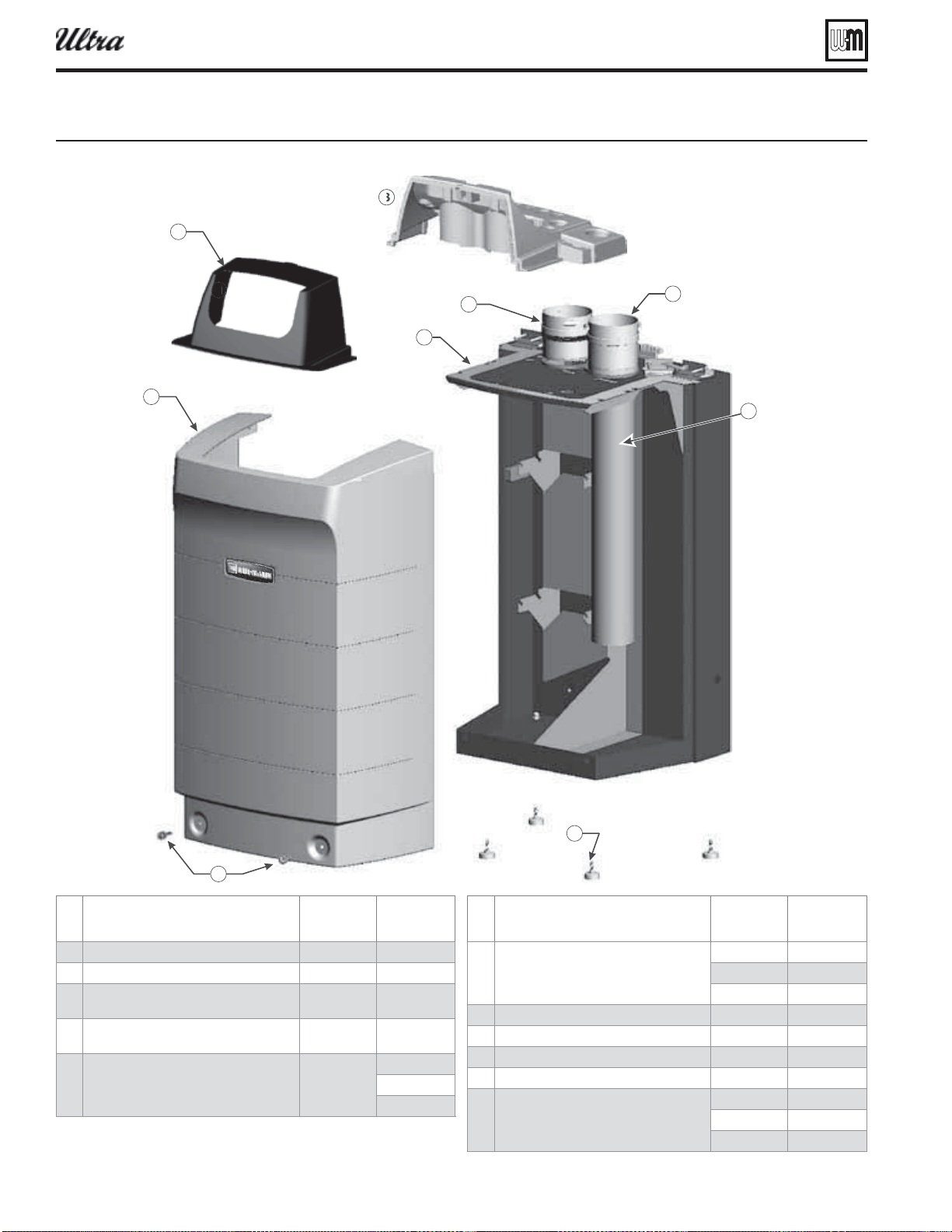
Part number 550-100-400/0119
130
Replacement parts (continued)
Figure 131 acet parts
Item
Description
Boiler
models
Part
number
1 Jacket front door All 383-500-135
2 Boiler leg kit (4 required) All 383-500-065
3
Screw fl at head slotted 17 Series for
jacket front door (2 required)
All 562-650-126
4
Screw clip-on receptacle (not shown)
(2 required)
All 383-500-180
5
Air inlet pipe adapter 3”
3”
4”
80/105
155
230–399
560-907-704
560-907-707
560-907-710
Item
Description
Boiler
models
Part
number
6 Flue outlet pipe adapter 3”
3”
4”
80/105 560-907-771
155 560-907-771
230–399 560-907-773
7 Top cover, front All 383-500-607
8 Top cover, rear 80/230 383-500-608
299/310/399 383-500-609
9 Door Gasket replacement kit (not shown) All 383-500-610
10 Flue pipe 3”
3”
4”
80/105 560-907-775
155 560-907-772
230–399 560-907-774
6
®
Series 4
gas-fired water boiler — Boiler Manual
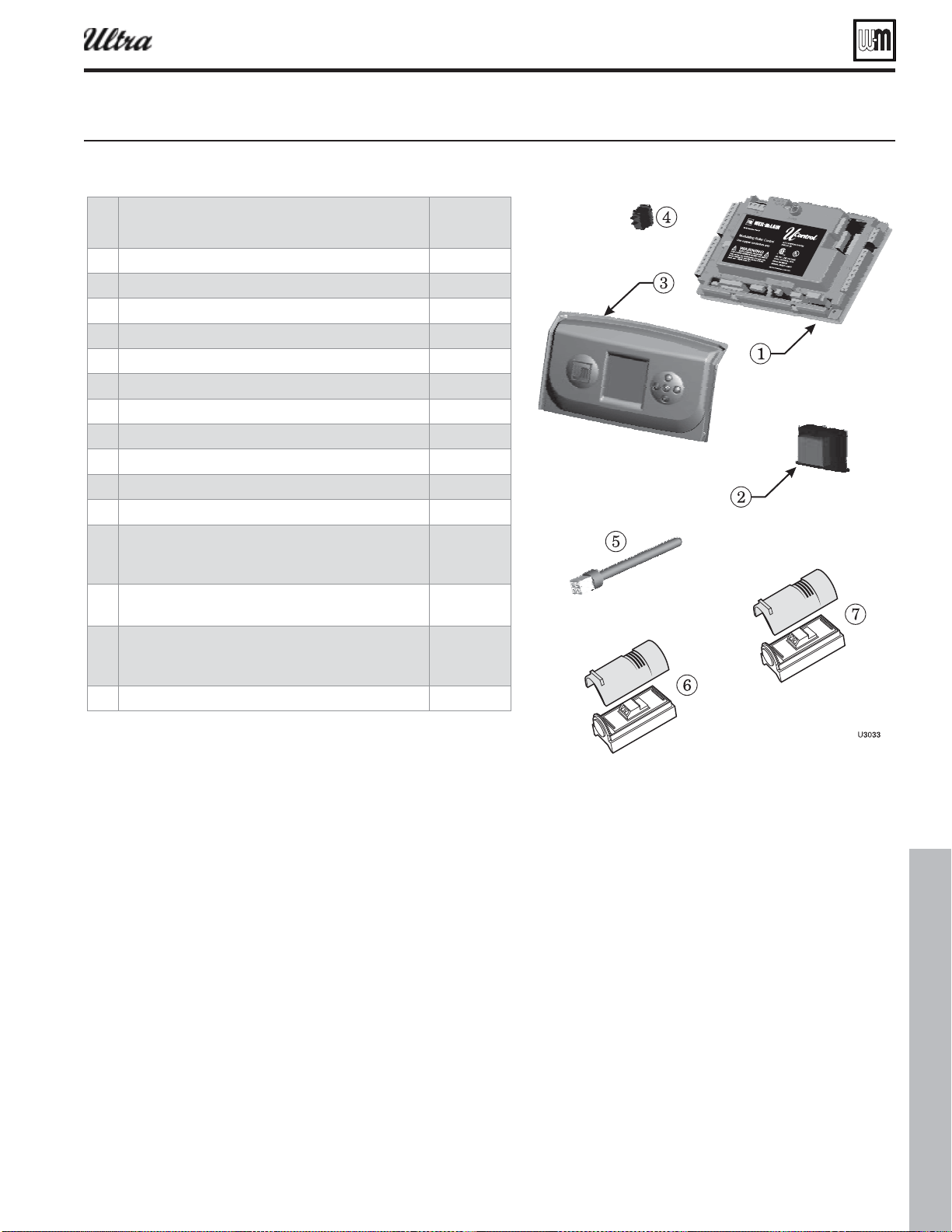
Part number 550-100-400/0119
131
Replacement parts (continued)
Figure 132 Controls
®
Series 4
gas-fired water boiler — Boiler Manual
Item
Description
Part
Number
Ultra U-Control module 383-500-658
Transformer, 120V/24V 383-500-628
Display board assembly (includes plastic and display screen) 383-500-756
On/off power switch 383-500-205
Flue temperature sensor replacement kit 383-500-600
System temperature sensors (2 required) 383-500-601
Outdoor temperature sensor 510-312-218
8
Display to U-Control wire harness (not shown) 383-500-633
Line voltage wire harness (male) (not shown) 383-500-639
Low voltage wire harness (male) (not shown) 383-500-640
120 volt, 3-wire receptacle (not shown) 383-500-638
Ultra U-Control module fuses (not shown)
F1 - 3-amp, fast-blow ATO (5 fuses)
F2 - 12-amp, fast-blow AG (5 fuses)
383-500-603
383-500-604
Jumper for low voltage terminal blocks, (5 jumpers)
(not shown)
383-500-641
Ultra U-Control terminal block kit, (includes 1 high voltage
terminal block, 6 low voltage terminal blocks, and U-Control
screwdriver) (not shown)
383-500-642
24V LWCO kit with quick connect harness (not shown) 511-100-005
Part number 550-100-400/0119
132
Replacement parts (continued)
Figure 133 eat echaner and pipin Ultra- and -
®
Series 4
gas-fired water boiler — Boiler Manual
Item Description
Boiler
Models
Part Number
80LP
8
& plugs
80
80LP
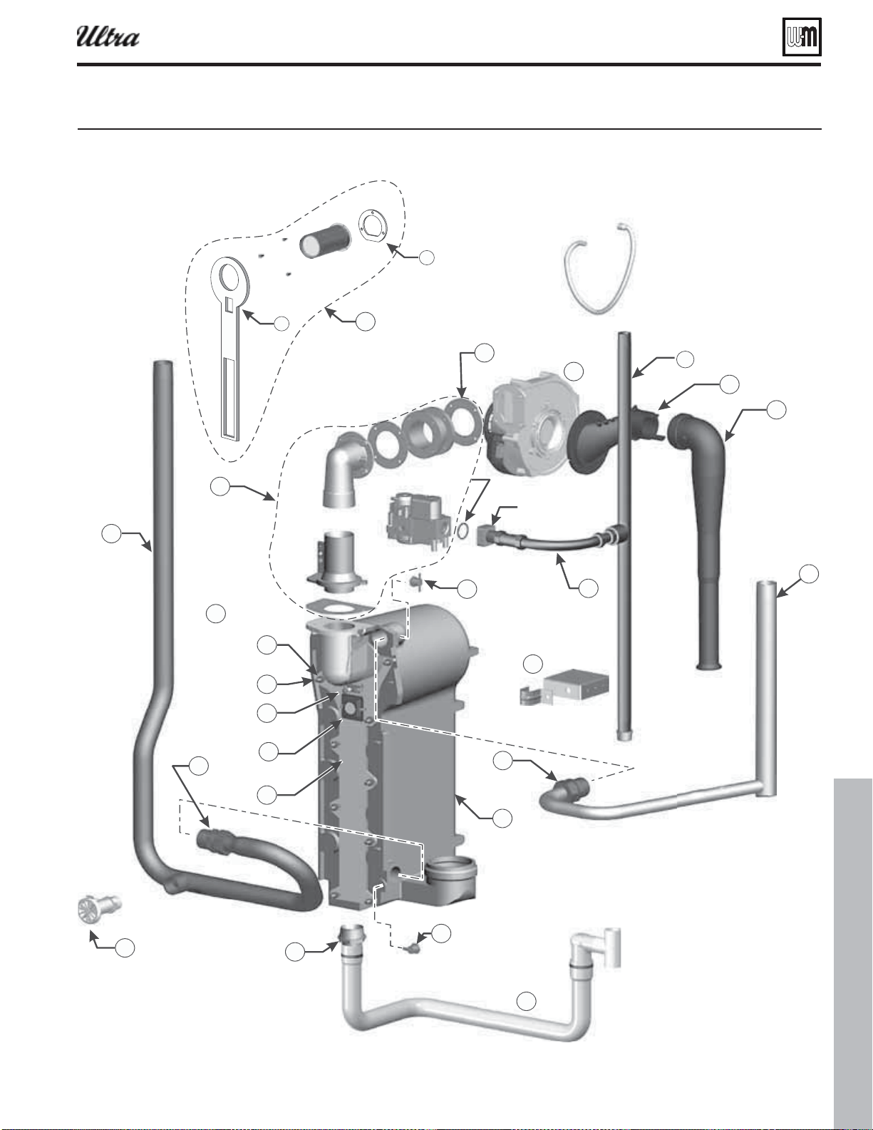
Part number 550-100-400/0119
133
6
(BTWBMWFTFOTPS
UVCJOH0%
GSPNHBTWBMWFUP
JOMFUFMCPX
&MCPX
7FOUVSJ
(BTWBMWF
(BTWBMWFJOMFU
BEBQUFSCMPDL
$PSLHBTLFU
0SJOH
Figure 134 eat echaner and pipin Ultra- and -
Replacement parts (continued)
®
Series 4
gas-fired water boiler — Boiler Manual
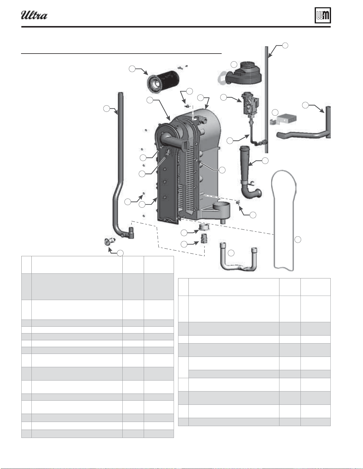
Part number 550-100-400/0119
134
6
Figure 135 eat echaner and pipin
Replacement parts (continued)
®
Series 4
gas-fired water boiler — Boiler Manual
Item
Description
Boiler
models
Part
number
1 Heat exchanger replacement kit - Heat
exchanger, cover plate, burner, electrode,
water sensors, compression fi ttings,
condensate fi tting, gaskets, and hardware
155
230
383-500-673
383-500-674
2 Cover plate replacement kit - Cover plate,
cover plate gasket, burner gasket, and
hardware
155/230 383-500-395
3 Cover plate insulation 155/230 383-500-250
4 Cover plate gasket 155/230 383-500-255
5 Cover plate studs, M6, 1 pitch All 560-340-598
6 Cover plate nuts, M6, 1 pitch All 561-928-449
7 Water compression fi tting, 28 mm 80–230 383-500-260
8 Supply water pipe assembly - Pipe &
compression fi tting & plugs
155/230 383-500-762
9 Return water bushing, 1 1/4” BSP x 1” BSP
(not use on Ultra-299/310)
155/230 383-500-280
10 Return water pipe assembly - Pipe, drain
valve, cap (assembled) & compression fi tting
155/230 383-500-763
11 Boiler drain valve, 3/4” NPT All 511-246-392
12 Blower assembly kit - Blower, gasket, and
hardware
155
230
383-500-035
383-500-040
13 Gas pipe 155/230 560-907-683
14 Flexible gas line 155/230 383-500-767
15 Gas pipe lower clamp and hardware 155/230 383-500-617
Item
Description
Boiler
models
Part
number
16
Gas valve/venturi kit - Gas valve, venturi,
adapter block, O-ring and hardware
(assembled) be sure to reinstall the existing
propane orifi ce)
155
230
383-500-025
383-500-030
17
Gasket cork, for in between gas valve venturi
& blower inlet (not shown)
All 590-317-310
18 Air silencer kit - Air silencer and gasket 155/230 383-500-295
19
Condensate trap kit - Condensate trap, hose
clamps, pvc fi ttings, and gasket
155/230 383-500-060
20
Ignition electrode kit - Ignition electrode,
suppressor, gasket, and hardware
All 383-500-045
Ignition electrode gasket ONLY (not shown) 511-330-253
21
Ignition cable kit (not shown) - Ignition cable,
suppressor, and wire tie
All 383-500-619
22
Inspection glass kit - Bracket, glass, gasket
and hardware
All 383-500-020
23
Burner replacement kit - Burner, gaskets and
hardware
155
230
383-500-085
383-500-090
24 Return/supply sensor kit - (1) sensor All 383-500-602
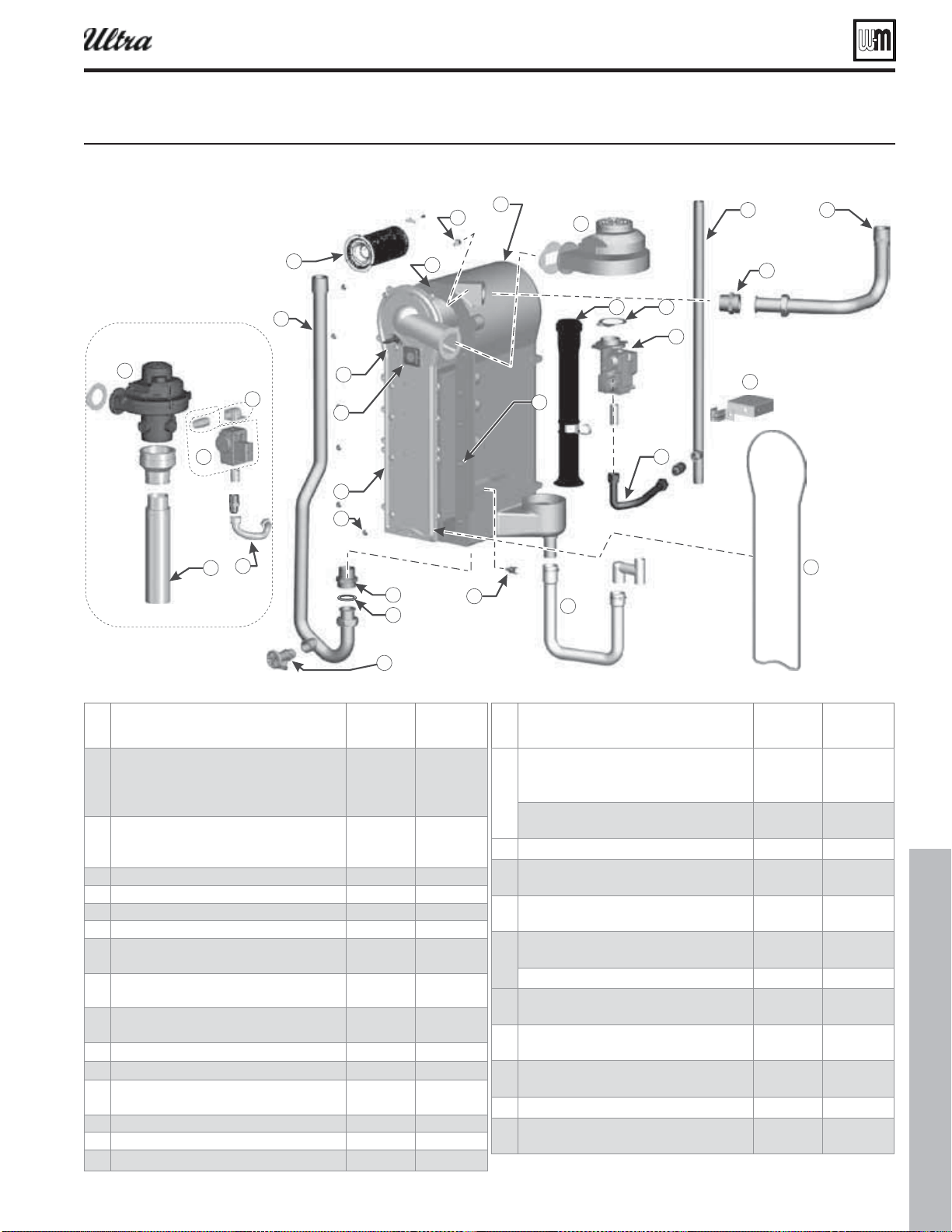
Part number 550-100-400/0119
135
6
DPNQPOFOUT
Figure 136 eat echaner and pipin
Replacement parts (continued)
®
Series 4
gas-fired water boiler — Boiler Manual
Item
Description
Boiler
models
Part
number
1 Heat exchanger replacement kit - Heat
exchanger, cover plate, burner, electrode,
water sensors, compression fi ttings,
condensate fi tting, gaskets, and hardware
299/310/399 383-500-675
2 Cover plate replacement kit - Cover plate,
cover plate gasket, burner gasket, and
hardware
299/310/399 383-500-395
3 Cover plate insulation 299/310/399 383-500-250
4 Cover plate gasket 299/310/399 383-500-255
5 Cover plate studs, M6, 1 pitch All 560-340-598
6 Cover plate nuts, M6, 1 pitch All 561-928-449
7 Supply water pipe assembly - Pipe &
compression fi tting & plugs
299/310/399 383-500-764
8 Return water pipe assembly - Pipe, drain
valve, cap (assembled) & compression fi tting
299/310/399 383-500-385
9 Supply/Return water piping square cut EPDM
gasket (Ultra-299/310 only)
299/310/399 562-248-755
10 Fitting, double nipple for supply/return 299/310/399 561-326-828
11 Boiler drain valve, 3/4” NPT All 511-246-392
12 Blower assembly kit - Blower, gasket, and
hardware
299/310
399
383-500-360
383-500-650
13 Gas pipe 299/310/399 560-907-679
14 Flexible gas line 299/310/399 383-500-768
15 Gas pipe lower clamp and hardware 299/310 383-500-625
Item
Description
Boiler
models
Part
number
16 Gas valve/venturi kit - Gas valve, venturi,
(For 310LP boilers, make sure to reinstall the
existing propane orifi ce)
299/310 383-500-390
Gas valve kit - Gas valve, venturi, adapter
block, O-ring and hardware (assembled)
399 383-500-652
17 Gas valve outlet adapter/nipple kit 399 383-500-651
18 Gasket cork, for in between gas valve venturi
& blower inlet
All 590-317-310
19 Air silencer kit - Air silencer and gasket 299/310
399
383-500-355
383-500-654
20 Ignition electrode kit - Ignition electrode,
suppressor, gasket, and hardware
All 383-500-045
Ignition electrode gasket ONLY 511-330-253
21 Ignition cable kit (not shown) - Ignition cable,
suppressor, and wire tie
All 383-500-619
22 Inspection glass kit - Bracket, glass, gasket
and hardware
All 383-500-020
23 Burner replacement kit - Burner, gaskets and
hardware
299/310 383-500-407
24 Return/supply sensor kit - (1) sensor All 383-500-602
25 Condensate trap kit - Condensate trap, hose
clamps, pvc fi ttings, and gasket
299/310/399 383-500-626
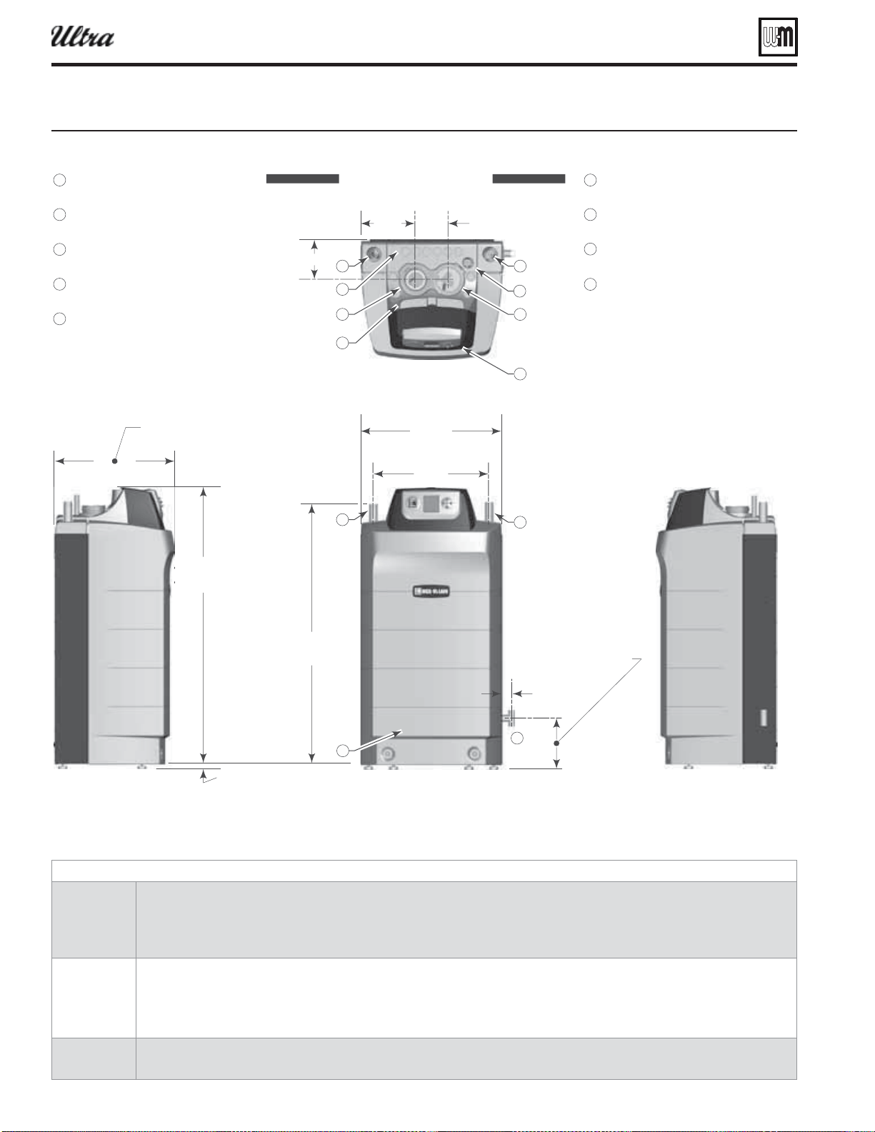
Part number 550-100-400/0119
136
Figure 137imensional data
Dimensions
®
Series 4
gas-fired water boiler — Boiler Manual
Notes
1
Boiler supply and return tappings are both 1” NPT (Ultra-80/105/155/230) or 1¼” NPT (Ultra-299/310/399).
See page 10 for recommended piping sizes.
Wall-hung boiler option — water piping and gas pipe can only be routed through top of enclosure using wall-mounting kit. See
page 5 for mounting instructions.
2
Boiler circulator is shipped loose.
Circulator must be mounted in the return piping.
Both 1” and 1¼” circulator fl anges are shipped with boiler on Ultra-80/105/155/230.
Both 1¼” and 1½” circulator fl anges are shipped with boiler on Ultra-299/310 and Ultra-399.
3
Relief valve is shipped loose.
See page 9 for mounting details. Relief valve mounts on supply pipe off of supply tee and ¾” street elbow as shown.
4VQQMZDPOOFDUJPOOPUF
3FUVSODPOOFDUJPOOPUF
7FOUDPOOFDUJPO
6MUSB
6MUSB
"
--
%*.&/4*0/4
*/
*/$)&4
-
&'5
'
30/5
3
*()5
5
01
&MFDUSJDBMFOUSBODFPQFOJOHT
$POUSPMQBOFM
(BTDPOOFDUJPOOPUF
$POEFOTBUFESBJO¡17$
"JSDPOOFDUJPO
6MUSB
6MUSB
%SBJOWBMWFJOTJEFFODMPTVSF
6
/PUF
ÑNJO67NBY
7
6MUSB
7N
6MUSB
67RF
6MUSB
6MUSB
)7
67N
67RF
6MUSB
7
6MUSB
7
7N67N
6MUSB
7
6MUSB
7
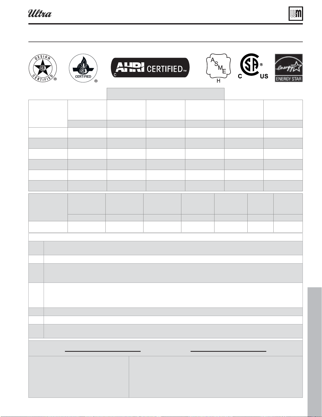
Part number 550-100-400/0119
137
Ratings — Ultra Series 4 boilers
Figure 138atins and enineerin data
®
Series 4
gas-fired water boiler — Boiler Manual
Btuh
(Note 7) Btuh (Note 2 and 7) AU (Note 1) Btuh (Note 3) allons
(Note 4)
Ultra-80 80,000 71,000 93.5 62,000 0.69 2” or 3”
Ultra-105 105,000 94,000 94.0 82,000 0.82 2” or 3”
Ultra-155 155,000 139,000 94.0 121,000 1.17 3”
Ultra-230 230,000 207,000 94.1 180,000 1.57 3” or 4”
Ultra-299 299,000 270,000 92.5 235,000 2.10 4”
Ultra-310 310,000 289,000 93.3 252,000 2.10 4”
Btuh (Note 7) Btuh (Note 7) Btuh (Note 3) Note 5) (Note 6) allons
(Note 4)
91.7 91.3 2.10
Notes
1
As an Energy Star Partner, Weil-McLain has determined that Ultra boilers meet the Energy Star guidelines for energy effi ciency.
NOTE: Adjusting boiler fi ring rate will affect AFUE rating.
2
Based on standard test procedures prescribed by the United States Department of Energy.
3
Net AHRI ratings are based on net installed radiation of suffi cient quantity for the requirements of the building and nothing need be
added for normal piping and pickup. Ratings are based on a piping and pickup allowance of 1.15. An additional allowance should be
made for unusual piping and pickup loads.
4
Ultra boilers require special venting, consistent with Category IV boiler.
Use only the vent materials and methods specifi ed in this manual.
Ultra-80 and -105 vent/air pipes can be either 2” or 3” pipe. Vent/air pipe length limits for 2” piping are not as long as for 3” piping.
Ultra-230 vent/air pipes can be either 3” or 4” pipe. Vent/air pipe length limits for 3” piping are not as long as for 4” piping.
5
Combustion effi ciency is based on AHRI testing procedure BTS-2000, and equal to 100% minus fl ue loss.
6
Thermal effi ciency is based on AHRI testing procedure BTS-2000.
7
Ratings shown are for sea level applications only. For altitudes from sea level to 5,500 feet above sea level, the Ultra boiler requires no
modifi cations and automatically derates itself by approximately 4% per 1000 feet above sea level.
OUTD OOR SENSOR
IMPORTANT
In accordance with
, this boiler is equipped with a
feature that saves energy by reducing the boiler
water temperature as the heating load decreases.
This feature is equipped with an override which
is provided primarily to permit the use of an
external energy management system that serves
the same function.
An external energy management system is installed that reduces the boiler water temperature
as the heating load decreases.
This boiler is not used for any space heating.
This boiler is part of a modular or multiple boiler system having a total input of 300,000 BTU/
hr or greater.
This boiler is equipped with a tankless coil (not applicable to Ultra boilers).
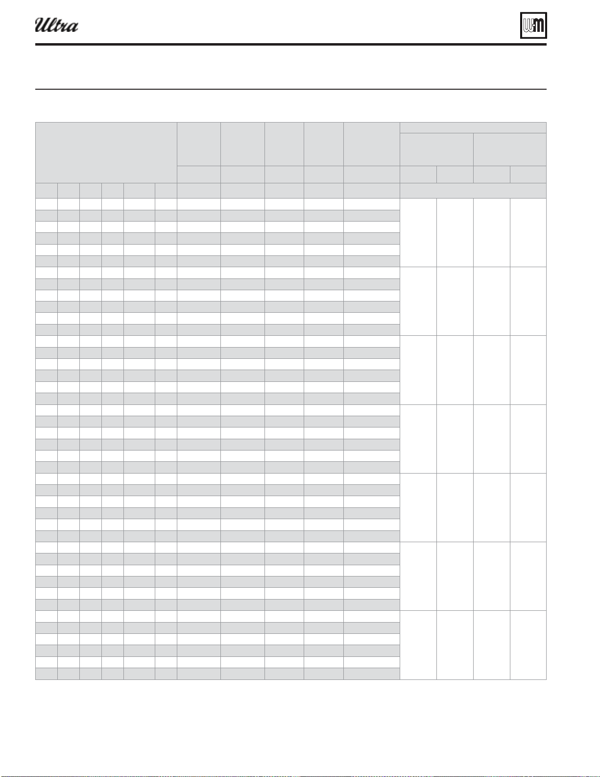
Part number 550-100-400/0119
138
Figure 139atins and enineerin data iure for notes
Boilers in system
Model Ultra –
Total
CSA
input
DOE
Heating
capacity
Boiler
H.P.
Net
water
ratings
Manifolded
combustion
air duct
size
Foundation size
Side-to-side
arrangement
(height 2” to 4”)
Back-to-back
arrangement
(height 2” to 4”)
Input
B
Output
B
- B
Suare
inches
Lenth
inches
Lenth
inches
Lenth
inches
Lenth
inches
8 0 10 5 1 5 5 2 3 0
2 9 9 /3 1 0
3 9 9
- Note 1 - Note 2
Figure 59, page 59
Note 3
2 160 142 4.2 123 80
56 23 27 48
2 210 188 5.6 163 105
2 310 278 8.3 242 155
2 460 414 12.4 360 230
2 598 540 16.1 468 299
2 798 730 21.8 634 385
3 240 213 6.4 185 120
85 23 56 48
3 315 282 8.4 245 157
3 465 417 12.5 363 232
3 690 621 18.6 540 345
3 897 810 24.2 702 449
3 1197 1095 32.7 951 578
4 320 284 8.5 247 160
114 24 56 49
4 420 376 11.2 327 210
4 620 556 16.6 483 310
4 920 828 24.7 720 460
4 1196 1080 32.3 936 598
4 1596 1460 43.6 1268 770
5 400 355 10.6 309 200
143 24 85 49
5 525 470 14 409 267
5 775 695 20.8 604 387
5 1150 1035 30.9 900 575
5 1495 1350 40.3 1170 748
5 1995 1825 54.5 1585 963
6 480 426 12.7 370 240
172 24 85 49
6 630 564 16.8 490 315
6 930 834 24.9 725 465
6 1380 1242 37.1 1080 690
6 1794 1620 48.4 1404 897
6 2394 2190 65.4 1902 1155
7 560 497 14.8 432 280
201 24 114 49
7 735 658 19.7 572 367
7 1085 973 29.1 846 542
7 1610 1449 43.3 1260 805
7 2093 1890 56.5 1638 1047
7 2793 2555 76.3 2219 1348
8 640 568 17 494 320
230 24 114 49
8 840 752 22.5 654 420
8 1240 1112 33.2 967 620
8 1840 1656 49.5 1440 920
8 2392 2160 64.5 1872 1196
8 3192 2920 87.2 2536 1539
Ratings — Multiple Ultra Series 4 boilers
®
Series 4
gas-fired water boiler — Boiler Manual
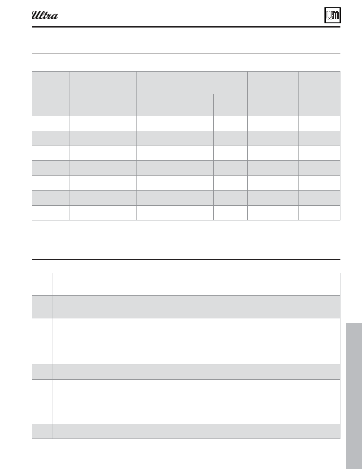
Part number 550-100-400/0119
139
Ratings — Multiple Ultra Series 4 boilers (continued)
Figure 140nineerin data see iure for notes
Boiler
Model
Ultra
Shipping
weight
Operating
weight
Water
content
Water fl ow rate
per boiler
Vent/air pipe
size —
Provide a
separate vent
for each boiler
Electrical
service
required
ounds
per oiler
ounds
per oiler
allons
per oiler
rise
rise
Amps
per oiler
Note Note Note
-80
199 139 0.7 7.1 3.6 2” or 3” 15.0
-105
207 145 0.8 9.4 4.7 2” or 3” 15.0
-155
234 181 1.2 13.9 7.0 3” 15.0
-230
246 192 1.6 20.7 10.4 3” or 4” 15.0
-299
297 229 2.1 27.9 14.0 4” 15.0
-310
297 229 2.1 28.9 14.5 4’ 15.0
-399
297 229 2.1 36.5 18.2 4” 15.0
Figure 141Notes for iure and iure
®
Series 4
gas-fired water boiler — Boiler Manual
1
Based on standard test procedures outlined by DOE for individual boilers.
2
Net AHRI ratings are based on piping and pickup allowance of 1.15.
Consult Weil-McLain Technical Services for other allowances.
3
Foundation sizes in Figure 139 provide 6 inches between boilers and 2 inches from boiler to edge of foundation.
Smaller foundations are possible with reduced service clearances.
See page 58 for details.
For side-to-side installations, see Figure 56, page 58 .
For back-to-back installations, see Figure 57, page 58 .
4
Operating weight is the total weight of the boiler, including water.
5
Ultra-80 and -105 vent/air pipes can be either 2” or 3” pipe. Vent/air pipe length limits for 2” piping are not as long as for 3” piping.
Ultra-230 vent/air pipes can be either 3” or 4” pipe. Vent/air pipe length limits for 3” piping are not as long as for 4” piping.
All Ultra installations require a separate vent pipe and termination for each boiler.
. Install and
terminate vents as described in vent/air installation instructions in this manual.
Combustion air piping can be individually piped or manifolded. See Figure 59, page 59 , for manifolded air piping.
6
Total amp requirement includes up to three circulators, not exceeding 2.2 amps per circulator.
gas-fired water boiler — Boiler Manual
®
Series 4
gas-fired water boiler — Boiler Manual
140
Installation and Service Certifi cate
Boiler Model CO
2
High fi re % CO
2
Low fi re %
Fuel Natural ____ LP ____ CO High fi re ppm CO Low fi re ppm
Was orifi ce changed? ______________________________________ Was gas valve throttle adjusted (Ultra-399) for propane? __________________
Natural gas input rate measured _________________________ Btuh
Boiler Model WWSD Temp °F Add’l Heat Demand Type 1___ 2___ 3___ 4___
High Altitude yes ____ no _____ Adjust Outdoor °F Add’l Heat Demand Time minutes
Manual Reset Temp °F
System Type System Type System Type
Max Supply °F Max Supply °F Max Supply °F
Min Supply °F Min Supply °F Min Supply °F
Max OD Reset °F Max OD Reset °F Max OD Reset °F
Min OD Reset °F Min OD Reset °F Min OD Reset °F
Modulate On Diff °F Modulate On Diff °F Modulate On Diff °F
Modulate Off Diff °F Modulate Off Diff °F Modulate Off Diff °F
Max On Time minutes Max On Time minutes Max On Time —
Min On Time — Min On Time minutes Min On Time minutes
Boost Interval minutes Boost Interval minutes Boost Interval minutes
Pre-pump Time: seconds Pre-pump Time: seconds Pre-pump Time: seconds
Post-pump Time: seconds Post-pump Time: seconds Post-pump Time: seconds
Circulator 1 on-off Circulator 1 on-off Circulator 1 on-off
Circulator 2 on-off Circulator 2 on-off Circulator 2 on-off
Circulator 3 on-off Circulator 3 on-off Circulator 3 on-off
Maximum Rate %Rate Maximum Rate %Rate Maximum Rate %Rate
Minimum Rate %Rate Minimum Rate %Rate Minimum Rate %Rate
Circulator 1 on _______ off _______ Circulator 1 on _______ off _______
Circulator 2 on _______ off _______ Circulator 2 on _______ off _______
Circulator 3 on _______ off _______ Circulator 3 on _______ off _______
Boiler Model
Series CP Number Date Installed
BTU Input ❏ Installation instructions have been followed.
❏ Check-out sequence has been performed.
❏ Above information is certifi ed to be correct.
❏ Information received and left with owner/maintenance person.
Installer
(Company) (Address) (Phone) (Installer's Signature)