Loading ...
Loading ...
Loading ...
Part number 550-100-400/0119
23
Figure 21
eet los eet los eet los
- 30 1 100 1
Not
alloed
- 30 1 100 1
- Not alloed 100 1
- Not alloed 30 1 100 1
- Not alloed Not alloed 100 1
- Not alloed Not alloed 100 1
Install reducers as necessar here connectin to the oiler
ent and air connections.
or pipin usin more than elo reduce maimum alloale
lenth
feet for each additional -inch elo or
feet for each additional
or -inch lon radius elo
feet for each or -inch short radius elo
feet for each or -inch -deree elo.
NOT The -deree return end is included in the alloed t-
tins. No deduction is reuired.
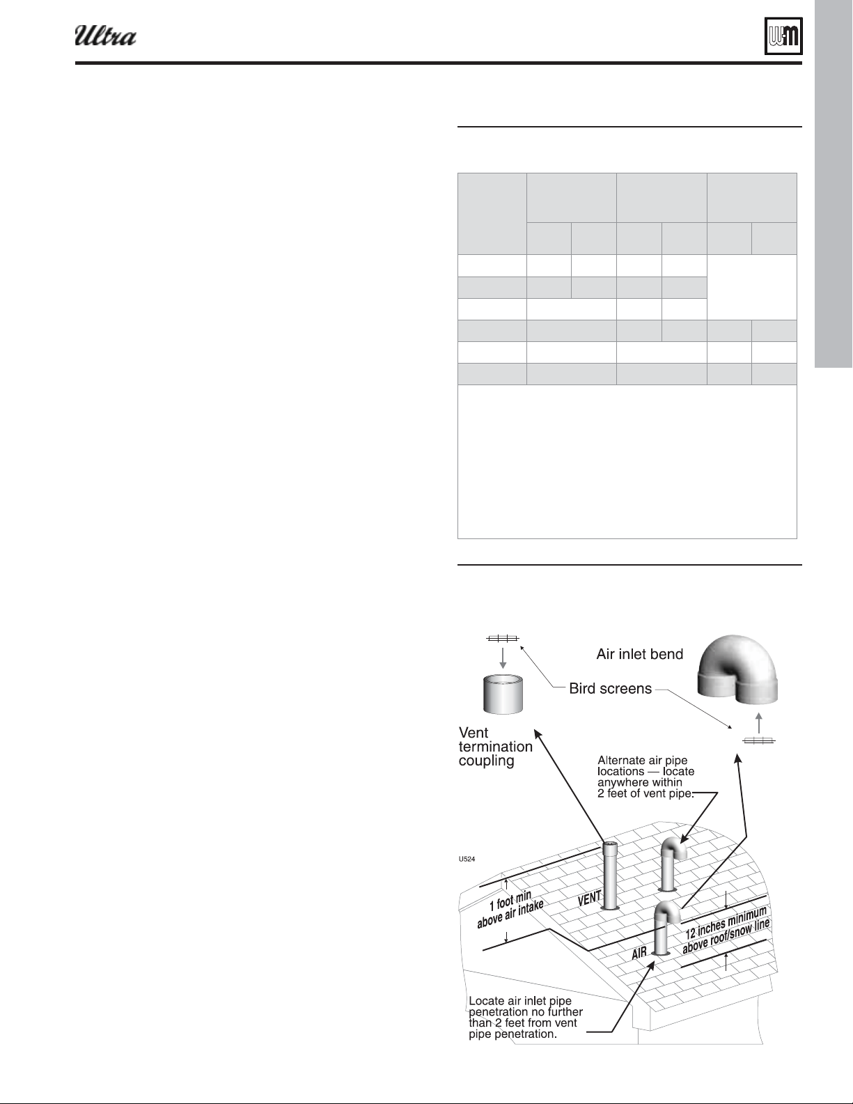
Figure 22ertical termination separate pipes
®
Series 4
gas-fired water boiler — Boiler Manual
Vertical vent/air termination: Separate pipes
Allowable vent/air pipe materials
1. Use only the materials listed in Figure 13, page 19 .
2. Purchase bird screens for vent and air terminations separately.
See the parts list at the end of this manual.
Maximum piping length
1. Locate the terminations such that the total air piping and vent
piping from the boiler to the termination will not exceed the
maximum length given in Figure 21 .
2. Maximum lengths listed in Figure 21 allow for 1 elbow. Ad-
ditional elbows required a reduction in maximum length as
explained in the table notes.
Connecting from termination to boiler
1. Install the termination penetrations as instructed in the follow-
ing. Then proceed to page 82 to complete the piping between
the termination and the boiler.
Determine location
1. Locate the vent/air terminations using the following guidelines:
2. The air piping must terminate in a down-turned 180-degree
return bend as shown in Figure 22 . Locate the air inlet pipe
no further than 2 feet from the center of the vent pipe. This
placement avoids recirculation of fl ue products into the com-
bustion air stream.
3. The vent piping must terminate in an up-turned coupling as
shown in Figure 22 . The top of the coupling must be at least 1
foot above the air intake. The air inlet pipe and vent pipe can
be located in any desired position on the roof, but must always
be no further than 2 feet apart and with the vent termination
at least 1 foot above the air intake.
4. You must consider the surroundings when terminating the
vent and air:
a. Position the vent termination where vapors will not dam-
age nearby shrubs, plants or air conditioning equipment
or be objectionable.
b. The fl ue products will form a noticeable plume as they
condense in cold air. Avoid areas where the plume could
obstruct window views.
c. Prevailing winds could cause freezing of condensate and
water/ice buildup where fl ue products impinge on building
surfaces or plants.
d. Avoid possibility of accidental contact of fl ue products
with people or pets.
e. Do not locate the terminations where wind eddies could
affect performance or cause recirculation, such as inside
building corners, near adjacent buildings or surfaces,
window wells, stairwells, alcoves, courtyards or other
recessed areas.
f. Do not terminate above any door or window. Condensate
can freeze, causing ice formations.
g. Locate or guard vent to prevent condensate damage to
exterior fi nishes.
Loading ...
Loading ...
Loading ...