Loading ...
Loading ...
Loading ...
Part number 550-100-400/0119
22
Sidewall vent/air termination: Separate pipes (continued)
Figure 19 ultiple terminations separate pipes
clearance from ent of one to air intae of the
net alternate con uration of air and ent
terminations
Figure 20 Sideall termination asseml usin
separate pipes
1 Vent piping
2 Air piping
3 Sidewall termination plates, by
installer
4 Galvanized thimbles, by installer
5 Bird screen (air), by installer
6 Air inlet elbow
7 Elbow
8 Nipple
9 Elbow (vent termination)
10 Alternate elbow orientation
11 Bird screen (vent termination) —
supplied by installer
®
Series 4
gas-fired water boiler — Boiler Manual
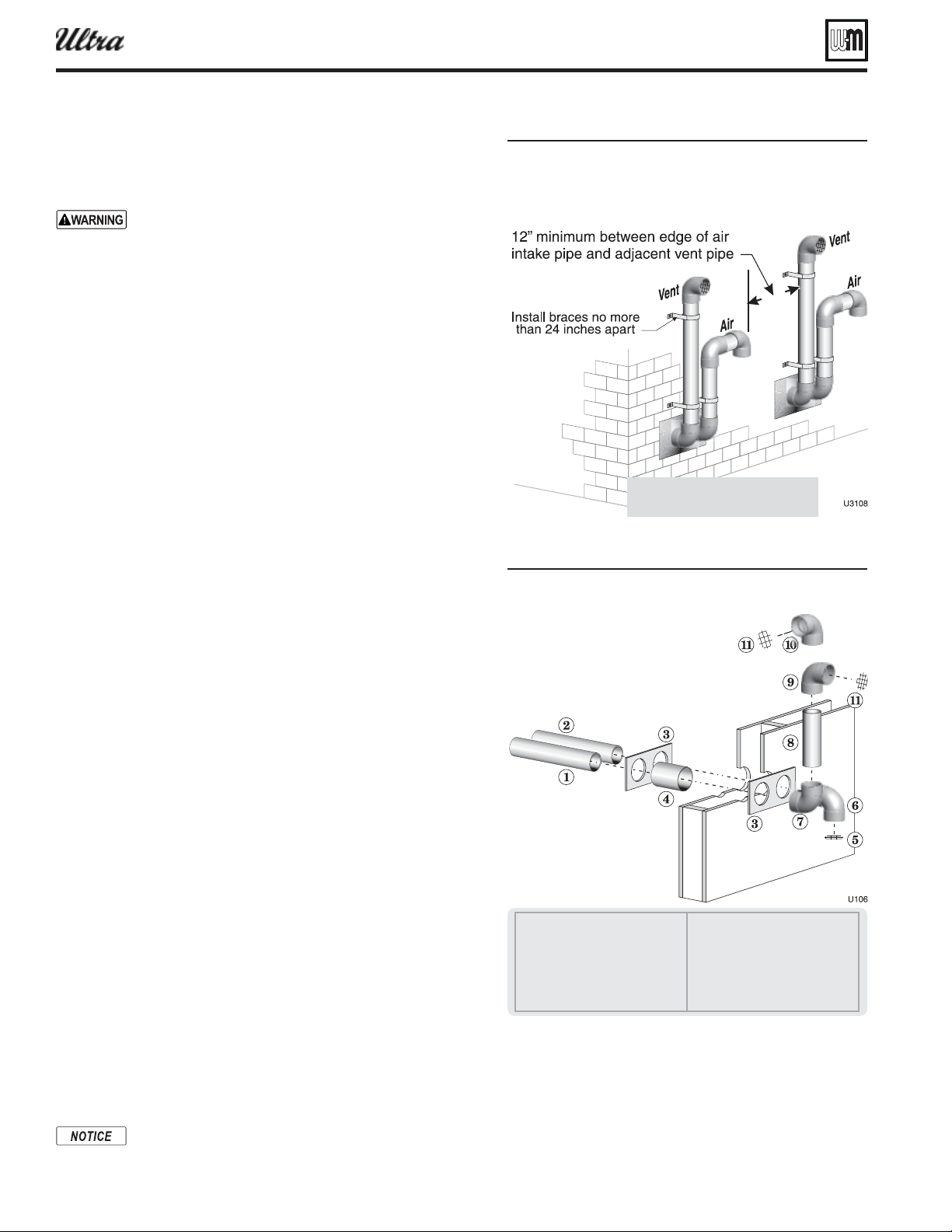
Multiple vent/air terminations
1. When terminating multiple Ultra boilers, terminate each vent/air
connection as described in this manual.
All vent pipes and air inlets must terminate at the same
height to avoid possibility of severe personal injury, death
or substantial property damage.
2. Place wall penetrations to obtain minimum clearance of 12 inches
between vent pipe and adjacent air inlet elbow, as shown in Fig-
ure 18, page 21 for U. S. installations.
3. For Canadian installations, provide clearances required by Natural
Gas and Propane Installation
CAN/CSA
B149.1 or B149.2 Instal-
lation Code.
4. The air inlet of an Ultra boiler is part of a direct vent connection.
It is not classifi ed as a forced air intake with regard to spacing from
adjacent boiler vents.
5. Combustion air (NOT vent piping) can be manifolded as shown
in Figure 59, page 59 .
Prepare wall penetrations
1. Air pipe penetration:
a. Cut a hole for the air pipe. Size the air pipe hole as close as desired
to the air pipe outside diameter.
2. Vent pipe penetration:
a. Cut a hole for the vent pipe. For either combustible or noncom-
bustible construction, size the vent pipe hole at least 0.4” larger
than the vent pipe diameter:
2¾” hole for 2”
4” hole for 3”
5” hole for 4”
b. Insert a galvanized metal thimble in the vent pipe hole as shown
in Figure 20 .
3. Use a sidewall termination plate as a template for correct location of
hole centers. Sidewall termination plates must be purchased sepa-
rately. See the parts list at the end of this manual for part numbers.
4. Follow all local codes for isolation of vent pipe when passing through
fl oors or walls.
5. Seal exterior openings thoroughly with exterior caulk.
Termination and fi ttings
1. Prepare the vent termination elbow and the air termination elbow
( Figure 20 ) by inserting bird screens. Bird screens must be pur-
chased separately. See the parts list at the end of this manual for
part numbers.
2. When completed, the air termination coupling must be oriented
at least 12 inches below the vent termination and at least 12 inches
above grade or snow line as shown in Figure 15, page 20.
3. You can orient the vent termination elbow either directly outward
or 90 degrees away from the air inlet elbow as shown in Fig-
ure 15, page 20.
4. Maintain the required dimensions of the fi nished termination piping
as shown in Figure 15, page 20.
5. Do not extend exposed vent pipe outside of building more than
shown in this document. Condensate could freeze and block vent
pipe.
If extending the vent and air pipes out from the wall,
install a coupling on each pipe. Mount the piping with
the coupling fl ush with the outer plate.
Loading ...
Loading ...
Loading ...