FL-5ES
08/10
Imported By: CANARM LTD., 2157 Parkedale Ave., Brockville, Ontario, K6V 5V6, Tel: (613) 342-5424, Fax: (613) 342-8437
electrical
box
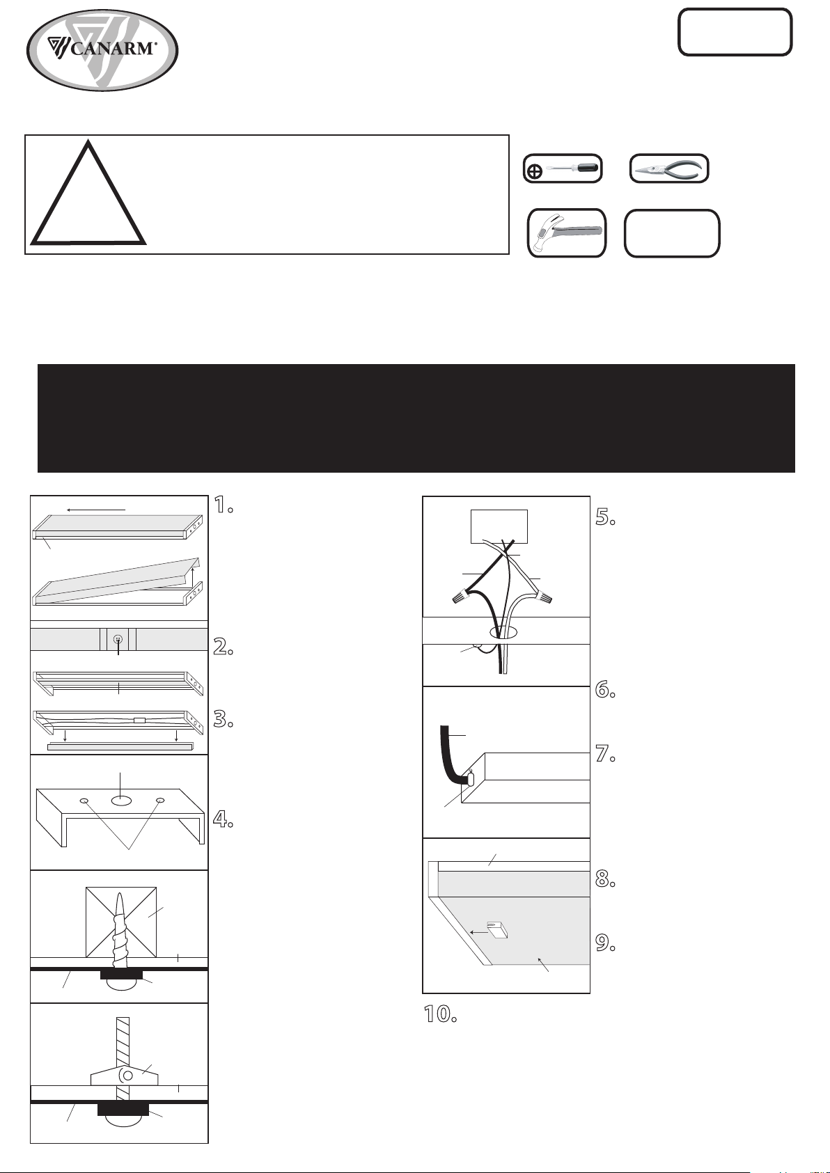
1. Remove the Acrylic Lens and
place aside to avoid possible damage.
Slide the lens towards one end of the
fixture. Gently press down the end of
the lens that is away from the housing.
(Be careful not to crack the lens.) This
will release the lens from the retaining
clip. Lift up this end and pull the lens
away from the fixture.
2. Remove the wire cover screw.
Using both hands, squeeze the wire
cover at both ends to release from the
housing and gently pull it away.
3. Turn the fixture over and locate
the center knockout. Make sure the
fixture is supported on the underside
and break part of the knockout away
using a hammer and screw driver.
Twist out the knockout using pliers.
4. Position the housing on the
ceiling with the center knockout over
the electrical box. Mark the ceiling for
the pilot hole locations through the
small holes on either end. Drill 1/8”
pilot holes at each location. Determine
the appropriate way of fastening the
fixture to the ceiling (wood screws or
toggle bolts, not included).
Note: Toggle bolts will require a larger
pilot hole. Secure the fixture to the
ceiling using the appropriate
fasteners. Connect the ground wire to
the ground screw located near the
center knockout. Connect the black
wire from the fixture to the black wire
from the electrical box. Connect the
white wire from the fixture to the
white wire from the electrical box.
Once wires are connected, carefully
tuck wires and marretts into the metal
outlet box.
5. Alternatively, if an outlet
(electrical) box is not available, if the
fixture doesn’t cover the outlet
(electrical) box entirely or if the
electrical leads are coming from either
end of the fixture, please consult a
qualified electrician for Armour Cable
or Conduit Electrical Feed type of
installation.
6. Replace the wire cover by
reversing the process of Step #2.
7. Install proper bulb type and
wattage. Insert the pins on both ends
of the fluorescent tube into the lamp
holders on both ends. Rotate the tube
until a slight "click" is felt. Repeat for
additional bulbs.
8. Replace the lens by reversing the
process of Step #1.
9. Insert the safety clip as shown in
both ends to avoid possible falling of
lens.
Lens
Fixture
wire cover
centre knockout
holes
wire cover screw
Toggle Bolt
washer
housing
ceiling
toggle bolt
white
wire
black
wire
ground wire
ground
screw
centre
knockout
end knockout
INSTALLATION:
armour cable or conduit
electrical feed
Consult a qualified
electrician
washer
housing
ceiling
joist
Wood Screw
Fixture
Lens
FLUORESCENT
LIGHTING
Star-headed
Screwdriver
Wiring supplies
as required by
electrical code
Pliers
Hammer
QUESTIONS OR CONCERNS, CONTACT CANARM AT:
1-800-265-1833 (English) 1-800-567-2513 (French) Monday through Friday 8:00 AM to 5:00 PM E.S.T.
TOOLS AND MATERIALS REQUIRED:
L
I
G
H
T
I
N
G
&
F
A
N
S
E
C
L
A
I
R
A
G
E
S
&
V
E
N
T
I
L
A
T
E
U
R
S
!
INSTRUCTIONS PERTAINING TO RISK OF FIRE OR INJURY TO PERSONS
READ ALL INSTRUCTIONS
IMPORTANT SAFETY
INSTRUCTIONS
SAVE THESE INSTRUCTIONS
SAFETY PRECAUTIONS:
1. TURN OFF ELECTRICAL POWER BEFORE STARTING INSTALLATION OF LIGHT FIXTURE.
2. THIS PRODUCT MUST BE INSTALLED IN ACCORDANCE WITH THE APPLICABLE INSTALLATION CODE BY A
PERSON FAMILIAR WITH THE CONSTRUCTION AND OPERATION OF THE PRODUCT AND THE HAZARDS
INVOLVED.
3. THIS FIXTURE IS DESIGNED FOR 120 VOLT CIRCUIT. IF UNSURE ABOUT WIRING, CONSULT AN ELECTRICIAN.
WARNING: DO NOT CONNECT FIXTURE TO DIMMER CIRCUIT.
4. THIS FIXTURE MUST BE GROUNDED PROPERLY. CONNECT THE GROUND WIRE (BARE COPPER OR GREEN) TO
THE AC SUPPLY GROUND WIRE (BARE COPPER OR GREEN) OR GROUND SCREW IN THE ELECTRICAL OUTLET
BOX. IF GROUND WIRE IS NOT AVAILABLE IN YOUR AC SUPPLY WIRE SYSTEM, PLEASE CONSULT A QUALIFIED
ELECTRICIAN BEFORE PROCEEDING THE ELECTRICAL CONNECTION.
5. USE ONLY ENERGY STAR APPROVED BALLAST (WITH LAMP SOCKETS) MANUFACTURED BY CSA FILE
NUMBER 226237 AND MARKETED BY CANARM LIMITED. THIS BALLAST IS REPLACEABLE BY A
QUALIFIED ELECTRICIAN WITHOUT CUTTING OF THE WIRES.
10. When the ballast is replaced, reverse the process from step 9 to 5.
Loosen the screw and nut to remove the ballast and sockets from fixture.
After that repeat the normal process from step 5 to 9.
