Loading ...
Loading ...
Loading ...
9
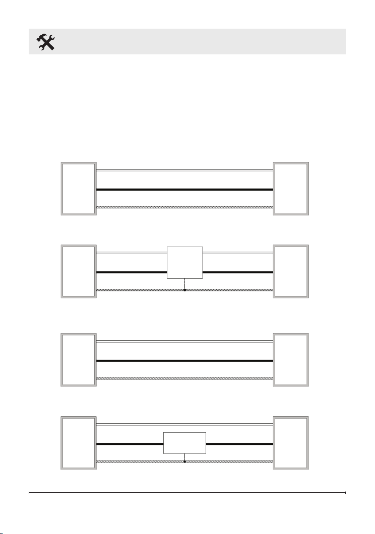
Wiring Instructions
WIRING INSTRUCTIONS:
DIR15A10GR is to be wired to a 120V circuit while DIR18A10GR and
DIR22A10GR are to be wired to a 240V circuit. These heaters must be
wired to the this circuit in such a way that the heater can be turned off
directly at the circuit breaker in the event of an emergency. Sample wiring
diagrams have been included below for quick reference.
Wall
Switch
Wall
Switch
Heater
Junction
Box
Heater
Junction
Box
Heater
Junction
Box
Heater
Junction
Box
120 V
Power
Supply
Breaker
Panel
120 V
Power
Supply
Breaker
Panel
240 V
Power
Supply
Breaker
Panel
240 V
Power
Supply
Breaker
Panel
240 V 15A
120 V 15A
L2
L1
G
L2
L1
G
L2
L1
G
G
L2
L1
L2
L1L1
L2
Indoor
Single Pole
120 V Switch
N (White)
L1 (Black)
G
G
L1
N
L1
L1
G
G
L1 (Black)
N (White)
N
L1
Use switch rated for
outdoor
applications,
if applicable
Indoor
Double Pole
240 V Switch
Use switch rated for
outdoor
applications,
if applicable
Use GFCI breaker
for outdoor
installations
Use GFCI breaker
for outdoor
installations
Use GFCI breaker
for outdoor
installations
Wall
Switch
Wall
Switch
Heater
Junction
Box
Heater
Junction
Box
Heater
Junction
Box
Heater
Junction
Box
120 V
Power
Supply
Breaker
Panel
120 V
Power
Supply
Breaker
Panel
240 V
Power
Supply
Breaker
Panel
240 V
Power
Supply
Breaker
Panel
240 V 15A
120 V 15A
L2
L1
G
L2
L1
G
L2
L1
G
G
L2
L1
L2
L1L1
L2
Indoor
Single Pole
120 V Switch
N (White)
L1 (Black)
G
G
L1
N
L1
L1
G
G
L1 (Black)
N (White)
N
L1
Use switch rated for
outdoor
applications,
if applicable
Indoor
Double Pole
240 V Switch
Use switch rated for
outdoor
applications,
if applicable
Use GFCI breaker
for outdoor
installations
Use GFCI breaker
for outdoor
installations
Use GFCI breaker
for outdoor
installations
Loading ...
Loading ...
Loading ...