7215590000R00
IMPORTANT SAFETY INFORMATION: Always read this manual rst
before attempting to install or use this heater. For your safety, always
comply with all warnings and safety instructions contained in this manual
to prevent personal injury or property damage.
To view the full line of Dimplex products, please visit
www.dimplex.com
Low
Med
High
on
Stan dby
Time r
1hr
2hr
Powe r/On
Model
DIR15A10GR
DIR18A10GR
DIR22A10GR
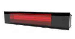
Dimplex DIR Series Indoor/
Outdoor Infrared Heaters
2 www.dimplex.com
Table of Contents
This manual covers installation
and maintenance. Read
carefully before attempting to
install, operate, or service the
Infrared heater.
!
NOTE: Procedures and
techniques that are considered
important enough to emphasize.
CAUTION: Procedures and
techniques which, if not carefully
followed, will result in damage to
the equipment.
WARNING: Procedures and
techniques which, if not carefully
followed, will expose the user to
the risk of re, serious injury, or
death.
Welcome & Congratulations .................3
IMPORTANT SAFETY INSTRUCTIONS ........4
Heater Installation ......................... 6
Wiring Instructions .........................9
Site Selection ............................10
Installation ..............................12
Electrical Installation ......................14
Operating Instructions .....................16
Maintenance ............................19
Troubleshooting ..........................20
Warranty ...............................21
3
Low
Med
High
on
Standb y
Timer
1hr
2hr
Power/ On
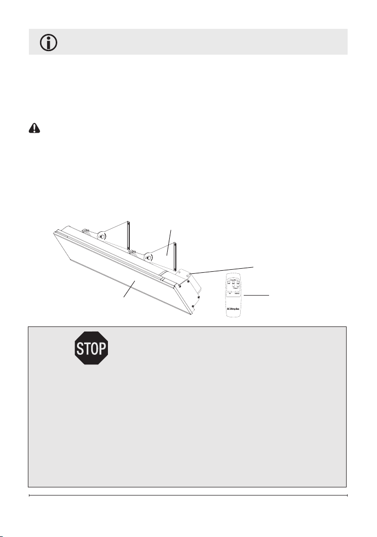
Welcome & Congratulations
Thank you and congratulations for choosing to purchase an IR Heater
from Glen Dimplex Americas.
Please carefully read and save these instructions.
CAUTION: Read all instructions and warnings carefully before
starting installation. Failure to follow these instructions may result in a
possible electric shock, re hazard and will void the warranty.
Please record your model and serial numbers for future reference.
Model and serial numbers can be found on the Model and Serial
Number Label of your heater.
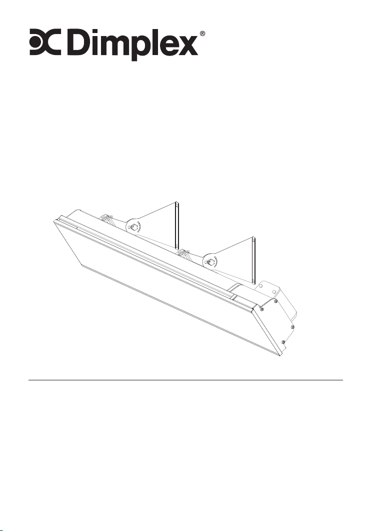
Terminal box
Brackets for wall or ceiling mounting
Remote control
Nextrema™ Schott
®
glass panel
NO NEED TO RETURN TO THE STORE
Questions with operation or assembly? Require Parts Information?
Product Under Manufacturer’s Warranty?
Contact us at: www.dimplex.com/customer_support
For Troubleshooting and Technical Support
OR Toll-Free 1-888-346-7539
Monday to Friday 8:00 a.m. to 4:30 p.m. EST
Please have your model number and
product serial number ready. (See above)

4 www.dimplex.com
IMPORTANT INSTRUCTIONS
When using electrical appliances,
basic precautions should always
be followed to reduce the risk of
fire, electric shock, and injury to
persons, including the following:
① Read all instructions before
installing or using this heater.
② Use this heater only as
described in this manual. Any
other use not recommended by
the manufacturer may cause re,
electric shock, or injury to persons.
③ This heater is hot when in use.
To avoid burns, do not let bare
skin touch hot surfaces. Keep
combustible materials, such as
furniture, pillows, bedding, papers,
clothes, and curtains at least 3.0
feet (0.9 m) from the front of the
heater and keep them away from
sides and rear restrictions.
④ Extreme caution is necessary
when any heater is used by or near
children or invalids and whenever
the heater is left operating and
unattended.
⑤ Do not operate any heater after
it malfunctions. Disconnect power
at service panel and have heater
inspected by a reputable electrician
before reusing.
⑥ Do not operate any heater
with a damaged cord or after it
malfunctions, has been dropped or
damaged in any manner. Return
heater to authorized service facility
for examination or mechanical
adjustment or repair.
⑦ To disconnect heater, turn off
power to heater circuit at main
disconnect switch, and turn off
power to heater circuit at main
disconnect panel.
⑧ Do not insert or allow foreign
objects to enter any ventilation or
exhaust opening as this may cause
an electric shock or re, or damage
the heater.
⑨ To prevent a possible re, do not
block air intakes or exhaust in any
manner.
⑩ A heater has hot and arcing or
sparking parts inside. Do not use
it in areas where gasoline, paint,
or ammable liquids are used or
stored.
5
IMPORTANT INSTRUCTIONS
CAUTION
RISK OF ELECTRIC SHOCK
DO NOT OPEN
NO USER-SERVICEABLE PARTS INSIDE
⑫
Do not touch the heater during
operation as the body becomes hot
and could causes burns. Particular
attention has to be given where
children and vulnerable people are
present.
⑬
This appliance is not intended for
use by persons (including children)
with reduced physical, sensory
or mental capabilities, or lack of
experience and knowledge, unless
they have been given supervision
or instruction concerning use of the
appliance by a person responsible
for their safety.
⑭
Do not allow any cables,
furnishing, ammable materials or
other items come in contact with
any surface of the heater.
The heater must not be located
immediately below a socket-outlet.
The heater must not be located in
front of a socket-outlet. They should
be located outside the physical
footprint of the units to minimize
heat build-up behind the heater.
WARNING: The heater must
not be used if the glass panels are
damaged.
WARNING: Keep combustible
materials such as furniture, papers,
clothes and curtains at least 3 feet
(0.9m) from the front of the heater
and keep them away from the sides
and rear.
!
NOTE: Changes or
modications not expressly
approved by the party responsible
for compliance could void user's
authority to operate the equipment.
SAVE THESE INSTRUCTIONS
FOR FUTURE REFERENCE
⑪
SAVE THESE INSTRUCTIONS.
⑮
6 www.dimplex.com
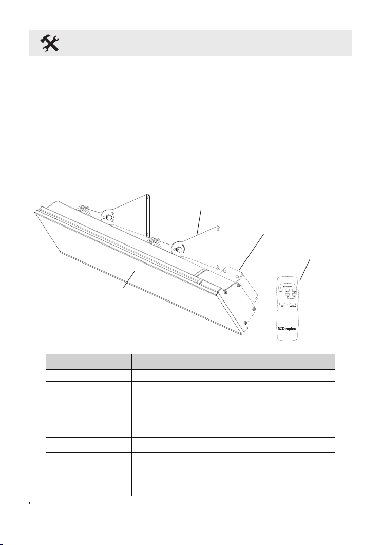
Heater Installation
HOW TO OPERATE THE HEATER:
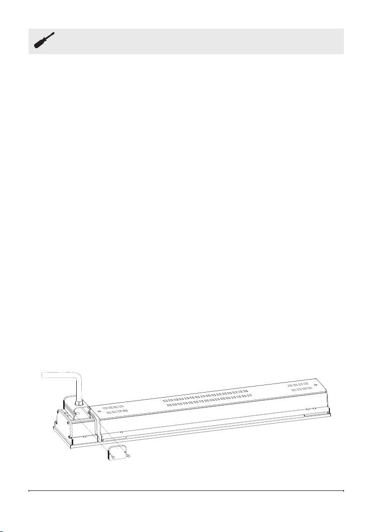
What's included with your Dimplex IR Heater
• IR Heater
• Operating and Installation Instructions
• One small box containing 2 sets of brackets and mounting hardware
• One remote controller
Figure 1
Technical Specication
Terminal box
Brackets for wall or ceiling mounting
Remote control
Nextrema ™ Schott ®:
glass panel
MODEL NAME DIR15A10GR DIR18A10GR DIR22A10GR
Voltage
120V~,60Hz 240V~,60Hz 240V~,60Hz
Rated power (Watts) 1500 1800 2200
Installation
Wall-mounted
Ceiling-mounted
Wall-mounted
Ceiling-mounted
Wall-mounted
Minimum Mounting Height 2.4M(7.9ft) 2.4M(7.9ft) 2.4M(7.9ft)
Electric protection class I I I
Outdoor rated yes yes yes
Unit dimensions
L x W x H (mm/in)
(without bracket)
902 x 170 x 78
35-1/2 x 6-3/4 x 3-1/8
902 x 170 x 78
35-1/2 x 6-3/4 x 3-1/8
902 x 170 x 78
35-1/2 x 6-3/4 x 3-1/8
7
Heater Installation
Before installation, read this
manual carefully and keep for
future reference.
The heater must be installed in
accordance with the manufacturer’s
installation instructions.
1. This equipment shall be installed
only by qualied personnel who
are familiar with the construction
and operation of the apparatus
and hazard involved.
WARNING: The heater is
tted with an electrical connection
box and should be connected as
a xed installation by a licensed
electrical professional. Wiring
procedures and connections should
be in accordance with the National
Electric Code (NEC) and local
codes.
RISK OF FIRE/
EXPLOSION
This heater should not be
used in potentially explosive
atmospheres. Do not use in
areas where gasoline, paint
or ammable liquids are used
or stored.
Installation minimum
clearances specied on the
heater nameplate and in the
owner's manual must be
followed.
2. Within USA, electrical installation
shall be made in accordance with
the National Electrical Code.
3. Within Canada, electrical
installation shall be made
according to the provisions of
section 62 of the Canadian
electrical code part 1.
4. Wiring procedures and
connections shall be in
accordance with the national and
local codes having jurisdiction.
CAUTION: Disconnect electric
power supply before working on
circuit wiring to prevent electric
shock.
CAUTION: When installing
outdoors we recommend the
heater is positioned where it will be
protected from exposure to extreme
weather such as snow and ice.
CAUTION: This heater must be
grounded.
CAUTION: Electrical connection
must have ground fault protection
(GFCI or GFI).
CAUTION: A circuit breaker is
required for proper installation, do
not load beyond 80% capacity.
CAUTION: High temperature,
risk of re, keep electrical cords,
drapery, furnishings, and other
8 www.dimplex.com
Heater Installation
combustibles at least 3 feet
(0.9 m) from the front of the heater
and away from the side and rear.
5. The heater is designed for
outdoor and indoor use and
should not be used for any
other purpose. Any other use
not recommended by the
manufacturer may cause re,
electric shock, or injury to
persons.
6. Before commencing installation
make sure the electrical supply
voltage is the same as that
shown on the rating plate of the
heater.
7. The heater must be mounted at
least 8 feet (2.4 M) above ground
level. For other clearance please
refer to the diagram included in
these instructions.
8. To reduce the risk of re, do not
store or use gasoline or other
ammable vapors and liquids in
the vicinity of the heater
9. The heater is not intended for
use in bathrooms, laundry areas
or similar indoor areas. Never
locate heater where it may fall
into a bathtub, pool, spa, or other
water container.
10. Do not install the heater directly
near a bathtub, shower or
swimming pool. Any switches
or controls must not be within
reach of a person in the
bathtub, shower or swimming
pool.
11. Ensure that the heater had been
securely fastened in its nal
mounting position.
12. The heater can be only installed
horizontally.
13. DO NOT install the heater
vertically. Failure to do this
may cause the heating element
within the tube to sag and
cause premature burnout.
14. There are no user-serviceable
parts inside the heater. Any
servicing other than regular
cleaning of the heater should
be performed by an authorized
service professional.
WARNING: The heater must
not be used if the glass panels
are damaged.
!
NOTE: This heater comes with
a pair of stainless steel adjustable
angle mounting brackets.
The adjustable angle enables
the heater to be installed on
horizontal and inclined surfaces.
9
Wiring Instructions
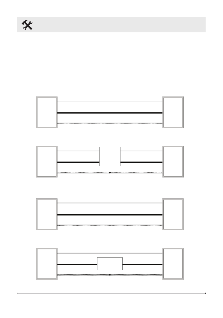
WIRING INSTRUCTIONS:
DIR15A10GR is to be wired to a 120V circuit while DIR18A10GR and
DIR22A10GR are to be wired to a 240V circuit. These heaters must be
wired to the this circuit in such a way that the heater can be turned off
directly at the circuit breaker in the event of an emergency. Sample wiring
diagrams have been included below for quick reference.
Wall
Switch
Wall
Switch
Heater
Junction
Box
Heater
Junction
Box
Heater
Junction
Box
Heater
Junction
Box
120 V
Power
Supply
Breaker
Panel
120 V
Power
Supply
Breaker
Panel
240 V
Power
Supply
Breaker
Panel
240 V
Power
Supply
Breaker
Panel
240 V 15A
120 V 15A
L2
L1
G
L2
L1
G
L2
L1
G
G
L2
L1
L2
L1L1
L2
Indoor
Single Pole
120 V Switch
N (White)
L1 (Black)
G
G
L1
N
L1
L1
G
G
L1 (Black)
N (White)
N
L1
Use switch rated for
outdoor
applications,
if applicable
Indoor
Double Pole
240 V Switch
Use switch rated for
outdoor
applications,
if applicable
Use GFCI breaker
for outdoor
installations
Use GFCI breaker
for outdoor
installations
Use GFCI breaker
for outdoor
installations
Wall
Switch
Wall
Switch
Heater
Junction
Box
Heater
Junction
Box
Heater
Junction
Box
Heater
Junction
Box
120 V
Power
Supply
Breaker
Panel
120 V
Power
Supply
Breaker
Panel
240 V
Power
Supply
Breaker
Panel
240 V
Power
Supply
Breaker
Panel
240 V 15A
120 V 15A
L2
L1
G
L2
L1
G
L2
L1
G
G
L2
L1
L2
L1L1
L2
Indoor
Single Pole
120 V Switch
N (White)
L1 (Black)
G
G
L1
N
L1
L1
G
G
L1 (Black)
N (White)
N
L1
Use switch rated for
outdoor
applications,
if applicable
Indoor
Double Pole
240 V Switch
Use switch rated for
outdoor
applications,
if applicable
Use GFCI breaker
for outdoor
installations
Use GFCI breaker
for outdoor
installations
Use GFCI breaker
for outdoor
installations
10 www.dimplex.com
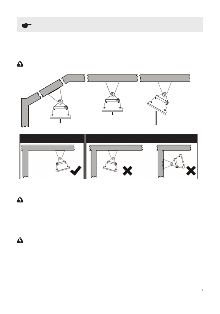
Site Selection
WARNING:
The heater must
never be installed in the upwards or
inwards facing position, the heating
surface must always be positioned
to direct the heat in a downwards or
outwards direction.
WARNING:
DO NOT install the
heater vertically. Failure to follow
these instructions can cause the
heating element within the tube to
sag and cause premature burnout.
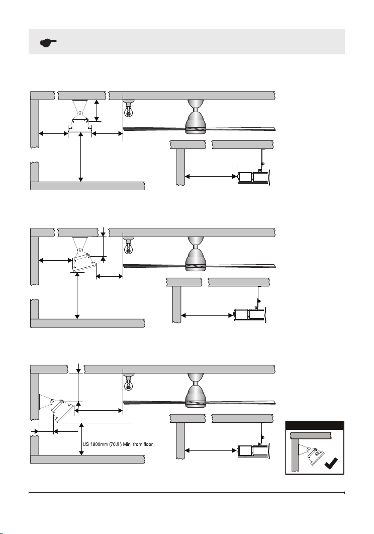
Clearances
To ensure that all minimum
clearances are achieved please refer
to the diagrams on page 11.
SITE SELECTION:
Ceiling mounted (DIR15A10GR, DIR18A10GR).
WARNING: DIR22A10GR CANNOT be ceiling-mounted.
Inclined ceiling-mount
Horizontal ceiling-mount
Angled horizontal ceiling-mount
Correct Installation Incorrect Installation
WALL
WALL
CEILING CEILING
WALL
CEILING
11
Site Selection
600mm
(23.6")
Min.
600mm
(23.6")
Min.
600mm (23.6") Min.
165mm
(6.5")
Min.
910mm (35.4") Min. to surfaces (ie. table tops, etc.)
3000mm (118.1") Max. from oor (recommended)
Fans, lights and
sprinkler fittings
MUST NOT
be below heater
IR heater, same minimum
clearance requirements
for both ends of heater
installation
WALL
CEILING
WALL
CEILING
Fans, lights and
sprinkler fittings
MUST NOT
be below heater
600mm
(23.6")
Min.
150mm
(5.9")
Min.
1500mm
(59.1")
Min.
600mm (23.6") Min.
910mm (35.4") Min. to surfaces (ie. table tops, etc.)
3000mm (118.1") Max. from oor (recommended)
WALL
CEILING
WALL
CEILING
IR heater, same minimum
clearance requirements
for both ends of heater
installation
Fans, lights and
sprinkler fittings
MUST NOT
be below heater
240mm (9.4")
Min.
1500mm (59.1")
Min.
105mm
(4.1") Min.
600mm (23.6") Min.
910mm (35.4") Min. to surfaces (ie. table tops, etc.)
WALL
CEILING
WALL
CEILING
IR heater, same minimum
clearance requirements
for both ends of heater
installation
Minimum clearances when mounting the heater at an angle to the ceiling.
Minimum clearances when mounting the heater on A VERTICAL WALL.
WALL
CEILING
Correct Installation
Wall-mounted
installation
(DIR15A10GR,
DIR18A10GR,
DIR22A10GR)
Minimum clearances when mounting the heater parallel with a ceiling.
Min. from Foor2100mm (94.5")
2100mm (94.5") Min. from Foor
Canada 2400mm (94.5") Min. from oor
12 www.dimplex.com
Installation
WARNING:
Mounting of the infrared heater and its connection to the
electric mains should be carried out only by qualied professionals according
to the Electrical Installation Regulations and Power System Safety Standards
and comply with all national and local electrical codes.
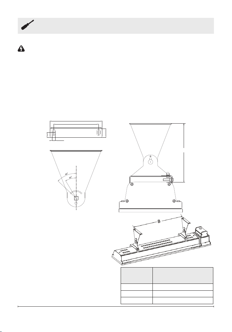
1. Open the package and carefully remove the heater.
2. Remove the packing paper sheet from the end of heater.
Model
Number
“B”
MINIMUM DISTANCE
DIR15A10GR
500 mm ±50 (19.7 in)
DIR18A10GR
500 mm ±50 (19.7 in)
DIR22A10GR
500 mm ±50 (19.7 in)
4. Use the above diagrams as a
guideline for proper installation.
Select the heater location on
the ceiling or wall by locating
the stud or structural beams to
ensure secure fastening of the
heater. Ensure that all minimum
clearances are achieved.
5. Install two brackets on the
ceiling or wall with the following
minimum recommended bracket
distance “B”. Ensure brackets are
level and not slanted diagonally.
165mm
(6.5")
117mm (4.6")
100mm (3.9")
11mm
(0.4")
7mm (0.3")
20mm
(0.8")
3. Take out one pair of mounting brackets. These adjustable brackets allow
direct ceiling or wall mount, and come with preset angle options of parallel,
30°, 45° and height 170 mm (6.7 in).
13
Installation
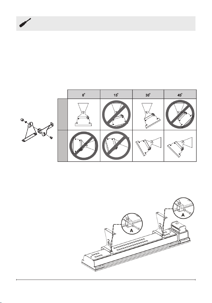
6. Set the adjustable angle mounting brackets to the desired angle and
fasten brackets with an adjustable wrench.
For ceiling-mounted installation, the available mounting angles are
For wall-mounted installation, the available mounting angles are restricted
7. Hang the heater on the brackets
and rmly tighten bolts on the
bracket to compress the two
plates together as shown in
Figure A.
!
NOTE:
Depending on material
and design of ceiling structural
elements, the heater must be
secured with the correct fasteners.
The weight of the heater is up to
5.3 KG (11.7 lbs.), the installation
location must be able to hold
5 times the weight
of the heater.
WALL CEILING
restricted to 0°, and 30° only.
to 30° and 45° only.
For the DIR 2200W, ceiling mounted installation is prohibited.
14 www.dimplex.com
Electrical Installation
WARNING:
This Heater MUST
be permanently installed and hard
wired by an authorized / licensed
electrical professional. Do not
perform maintenance or carry out
installation or assembly procedure
while electrical power is switched on.
CAUTION:
A circuit breaker is
required for proper installation. Do
not load beyond 80% capacity.
1. DIR15A10GR (1500W) is
designed for connection to the
120V~ 60Hz electric mains
equipped with a grounding wire
2. DIR18A10GR (1800W) and
DIR22A10GR (2200W) heater
is designed for connection to
the 240V~ 60Hz electric mains
equipped with a grounding wire
3. The heater must not be located
immediately below an electrical
connection. Power point should
not be located at the back of the
heater. The power point needs to
be located outside the physical
footprint of the heater to minimize
heat build-up behind the heater.
4. If the heater is to be mounted on
an incline (e.g. Vaulted ceiling),
ensure the electrical connection
point is below the heater.
be C curve type.
The type of circuit breaker must
15
Electrical Installation
WIRING INSTRUCTIONS
1. Check product label for correct
voltage and wattage. Make sure
power source conforms to the
heaters requirements.
2. The junction box on the top of
the heater has a gasket side
access cover. The junction box
inlet is drilled and threaded for a
standard 1/2" (19 mm) weather
tight conduit ttings. The installing
electrician will need to provide the
appropriate rigid metallic, exible
or liquid tight conduit, conduit
ttings for installation location.
3. For outdoor installation all
connections must be made
in accordance with local
electrical code regulations for
outdoor wiring. Only use wiring
components approved for outdoor
use with minimum NEMA Type 4x
or equivalent.
4. Remove the screws holding the
junction box cover. Make the
electrical connections using wire
nuts (not supplied). The green
wire connects to the ground. The
black wire connects to the black
wire (neutral) from your house.
The white wire connects to the
white wire (live) from your house;
5. Assemble the junction box cover
& gasket. Ensure that the junction
box cover gasket (supplied with
unit) is installed to maintain
rain water ingress protection
rating of the heater. failure to
install correctly will void the
manufacturer’s warranty.
16 www.dimplex.com
Operating Instructions
WARNING:
The heater must be properly installed before it is used.
Slight crackles may be heard during the heating or cooling period. This is a
normal part of the operation of the heater.
!
NOTE:
After switching on the heater for the rst time following extended
periods on non-use, the appliance may produce a slight odor for a short time.
This is normal and will not affect the use of the heater.
RISK OF FIRE/EXPLOSION
• This heater should not be used in potentially explosive atmospheres or
environments. Do not use in areas where gasoline, paint or ammable
liquids are used or stored.
• Keep electrical cords, drapery, furnishings, insulation and other
combustibles at least 3 feet (0.9 m) from the front of the heater and away
from the top, rear, and sides of the unit.
• To prevent possible res, do not block or allow foreign objects to enter
air intakes.
ELECTRICAL SHOCK HAZARD
• Do not operate heating unit after a malfunction. Disconnect power at the
service panel and have the heater inspected by a qualied electrician
before reusing.
• Use this heater only as described in this manual. Any other use is not
recommended by the manufacturer and may result in re, electric shock,
or injury.
• Do not insert or allow foreign objects to enter any ventilation or exhaust
opening as this may cause an electric shock or re, or damage the heater.
RISK OF INJURY/BURN
• The heating unit and discharge area will be hot when in use. To avoid
burns, do not let bare skin touch the heating unit or glass surface on
heating unit.
• Do not attempt to service or clean heater while unit is operating, as there
is a hazard from electric shock and burn potential from hot surfaces. To
avoid the risk of burn or injury wait a minimum of 6 hours for the heater to
cool before attempting to clean or service.
17
Operating Instructions
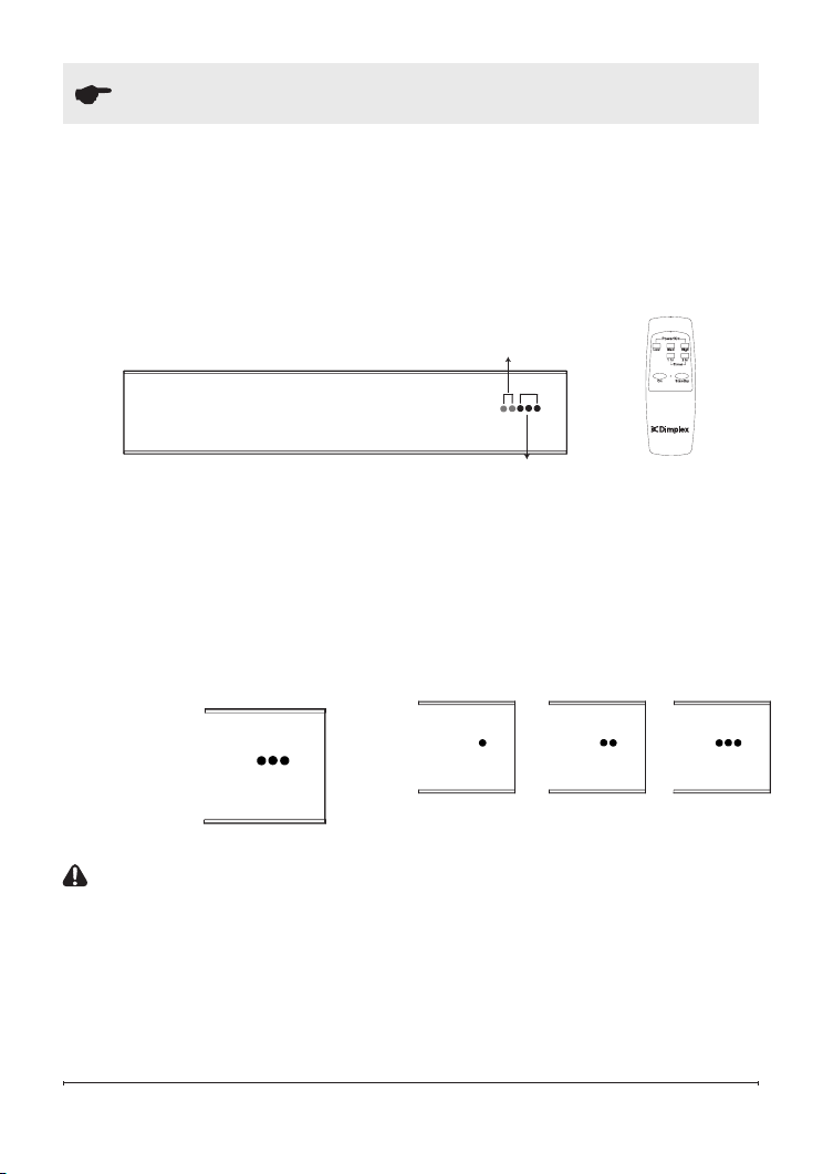
1.
Switch on the circuit breaker,
the heater will begin in Standby
mode. At this time the lowest heat
temperature setting LED will be
ashing to indicate the unit is in
Standby.
2.
Point the remote control directly
to the receiver, press ‘LOW’,
‘MED’, ‘HIGH’ to set your desired
temperature setting.
Green LED indicators
(timer)
Remote
control
Red LED indicators
(temperature setting)
Remote
control
Low power level
Medium power level
High power level
!
NOTE:
To prevent unpleasant burnt odor, it is recommended to keep the
heater clean preventing accumulation of dust build up
!
NOTE:
The distance between the heater and the remote control should
be less than 3 M (9.8 ft.), and the remote control must be pointed directly to
the receiver on the front panel during the operation.
CAUTION:
There is a built in
safety feature that will automatically
trigger the heater to go into standby
mode after eight hours of continuous
operation. At this time the lowest
heat temperature setting LED will be
ashing to indicate the safety feature
has executed.
3.
To set the heater to standby
mode point the remote control
directly at the receiver and press
‘STANDBY’. At this time the
lowest heat temperature setting
LED will be ashing to indicate the
unit is in STANDBY mode.
18 www.dimplex.com
Operating Instructions
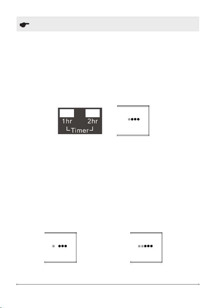
TIMER FUNCTION
Your Dimplex infrared heater comes with a programmable timer that will
automatically place the heater in STANDBY mode after 1, 2 or 3 hours
of operation. To operate the timer point the remote control directly to the
receiver and press ’1 hr’, a single green LED light will illuminate directly
beside the heating LED’s, this will trigger the heater to automatically go into
STANDBY mode after 1 hour (60 minutes) of operation. Once in STANDBY
mode a single red LED will be ashing.
1 hour timer
2 hour timer
2 hour timer
3 hour timer
3 hour timer
2. To set the timer for 3 hours of
operation point the remote control
directly to the receiver and press
’1 hr’ and ‘2 hr’, both green LED
lights will illuminate, this will trigger
the heater to automatically go into
STANDBY mode after 3 hours
(180 minutes) of operation. Once
in STANDBY mode a single red
LED will be ashing.
1. To set the timer for 2 hours of
operation point the remote control
directly to the receiver and press
’2 hr’, a single green LED light
will illuminate with a gap between
the heat and timer LED’s on the
unit, this will trigger the heater to
automatically go into STANDBY
mode after 2 hours (120 minutes)
of operation. Once in STANDBY
mode a single red LED will be
ashing.
19
Maintenance Instructions
WARNING:
When replacing the
ruby bulb or when cleaning the unit
ensure that if hard wired the circuit is
disconnected from the main power
supply.
!
NOTE: ALWAYS ENSURE THAT
THE BULB HAS COOLED BEFORE
HANDLING.
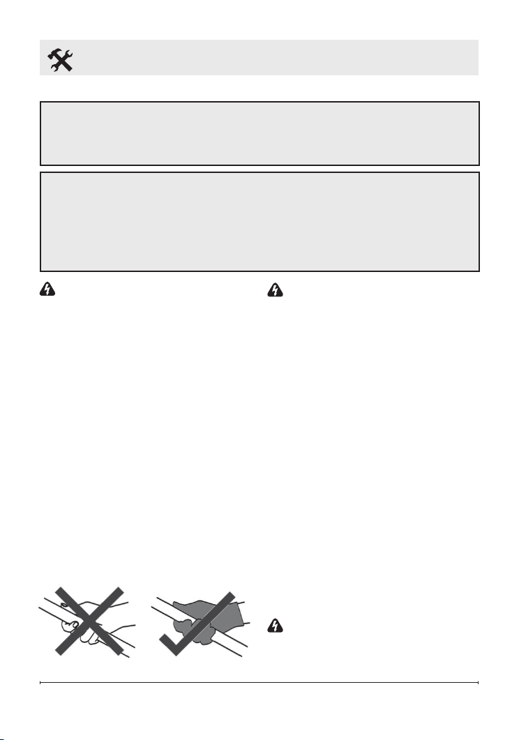
1. Do not handle the halogen
bulb with bare hands. If it is
inadvertently touched, remove
nger marks with a soft cloth
and methylated spirit or rubbing
alcohol. Otherwise, the marks will
burn into the quartz emitter during
use causing premature heater
failure.
WARNING:
All maintenance
should only be carried out by a
qualied electrician or installation
professional.
2. During operation, it is necessary
to periodically (once a year) check
the electric cable contacts and
terminal connectors for good
tightening.
3. Before cleaning the unit, the
power shall be turned off at the
circuit breaker panel, and the
heating unit must be cool to the
touch to prevent bodily injury.
4. If the body becomes dirty, wipe off
dust with a towel. The radiating
boards should be wiped in cold
condition with a damp soft rag.
It is recommended to clean the
unit every 3 months for peak
performance.
WARNING:
Never immerse
the heater in water! Doing so could
cause damage, bodily injury or
death.
ELECTRIC SHOCK HAZARD
• Potentially lethal voltages are present. Be sure to turn off the unit at the
circuit breaker before attempting any maintenance
RISK OF INJURY/BURN
• Do not attempt to service or clean heater while unit is operating, as there
is a hazard from electric shock, and injury potential from hot heating
elements.
• Maintenance and repair must be performed by qualied personnel only.
20 www.dimplex.com
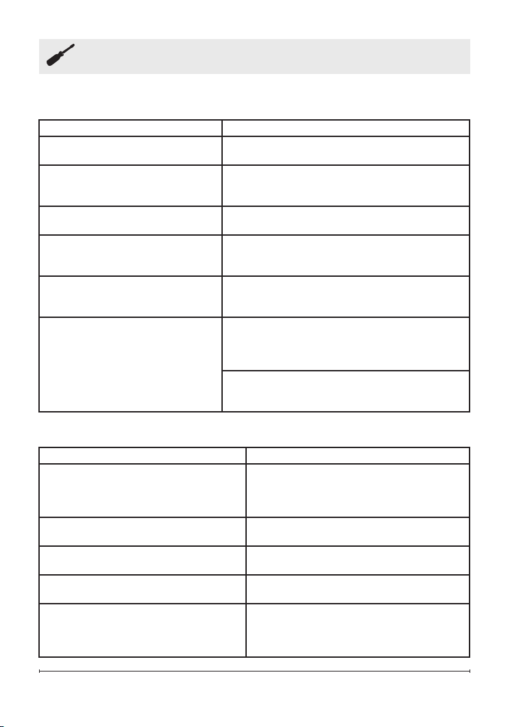
Troubleshooting
Troubleshooting prior to calling a service technician:
When to contact the authorized service technician or your dealer:
SYMPTOM
RECOMMENDED ACTION
Will not heat / No operation
indicator LED
Check that power is connected and switched
on
Heater smells when rst used
This is caused by oil or dust left over from the
manufacturing process and will stop after a
short time
Faint smell for short periods after
turning on the heater
This is normal and should stop after a short
time
Heater smells when turned on
after periods of non-use
This is the result of build-up debris and dust in
the heater, Switch the heater off and allow it to
cool down and then clean before operating
Clinking noises when heater
is turned on and after being
turned off
This is expansion and contraction noises of
the heaters metal components and is a normal
function of the heater
Poor heating performance
Exposure to extreme ambient conditions such
as high winds / excessively cold temperatures
can lower the heating performance of an
outdoor installation
Unit is not installed in correct position,
possibly too high or heater is too small for
recommended area.
SYMPTOM
RECOMMENDED ACTION
There is a burning smell and or
strange sounds (other than normal
expansion and contraction noises)
coming from the unit
Turn off the heater, and contact your
dealer
When associated circuit breaker
(safety, ground) trips or a fuse is blown
Turn off the heater, and contact your
dealer or a certied electrical technician
Poor heating performance Incorrectly sized installation, contact your
dealer for more information
Poor heating performance Faulty heater element, turn off the heater,
and contact your dealer
Will not heat / No operation indicator Check that power is connected and
switched on, if still faulty turn off the
heater, and contact your dealer or a
certied electrical technician.

21
Warranty
One Year Limited Warranty
Products to which this limited warranty
applies
This limited warranty applies to your newly
purchased Dimplex Infrared Indoor/Outdoor
Heater. This limited warranty applies only to
purchases made in any province of Canada
except for Yukon Territory, Nunavut, or
Northwest Territories or in any of the 50
States of the USA (and the District of
Columbia) except for Hawaii and Alaska.
This limited warranty applies to the original
purchaser of the product only and is not
transferable.
Products excluded from this limited
warranty
IR Ruby Heating Elements are not covered
by this limited warranty and are the sole
responsibility of the owner/purchaser.
Products purchased in Yukon Territory,
Nunavut, Northwest Territories, Hawaii,
or Alaska are not covered by this limited
warranty. Products purchased in these
States, provinces, or territories are sold AS
IS without warranty or condition of any kind
(including, without limitation, any implied
warranties or conditions of merchantability
or tness for a particular purpose) and
the entire risk of as to the quality and
performance of the products is with the
purchaser, and in the event of a defect the
purchaser assumes the entire cost of all
necessary servicing or repair.
What this limited warranty covers and for
how long
Products covered by this limited warranty
have been tested and inspected prior to
shipment and, subject to the provisions of
this warranty, Glen Dimplex Americas Ltd.
(Glen Dimplex Amerias herein) warrants
such products to be free from defects in
material and workmanship for a period of 12
months from the date of the rst purchase
of such product.
The limited 12 month warranty period
also applies to any implied warranties that
may exist under applicable law. Some
jurisdictions do not allow limitations on how
long an implied warranty lasts, so the above
limitation may not apply to the purchaser.
What this limited warranty does not cover
This limited warranty does not apply
to products that have been repaired
(except by Glen Dimplex Americas or its
authorized service representatives) or
otherwise altered. This limited warranty
does further not apply to defects resulting
from misuse, abuse, accident, neglect,
incorrect installation, improper maintenance
or handling, or operation with an incorrect
power source.
What you must do to get service under this
limited warranty
Defects must be brought to the
attention of Technical Service by
contacting 1-888-346-7539. Please have
proof of purchase, catalogue/model and
serial numbers available when calling.
Limited warranty service requires a proof
of purchase of the product.
What Glen Dimplex Americas will do in the
event of a defect
In the event a product or part covered by this
limited warranty is proven to be defective
in material or workmanship during the 12
month limited warranty period you have the
following rights:

22 www.dimplex.com
• Glen Dimplex Americas will in its sole
discretion either repair or replace such
defective product or part without charge.
If Glen Dimplex Americas is unable
to repair or replace such product or
part, or if repair or replacement is not
commercially practicable or cannot be
timely made, Glen Dimplex Americas
may, in lieu of repair or replacement,
choose to refund the purchase price for
such product or part.
• Limited warranty service will be
performed solely by dealers or service
agents of Glen Dimplex Americas
authorized to provide limited warranty
services.
• The purchaser is responsible for
removal and transportation of such
product or part (and any repaired or
replacement product or part) to and
from the authorized dealer’s or service
agent’s place of business.
• This limited warranty does not entitle
the purchaser to on-site or in-home
services. On-site or in-home services
may be performed at the purchaser’s
specic request and expense at Glen
Dimplex Americas then-current rates for
such services.
• Glen Dimplex Americas will not be
responsible for, and the limited warranty
services shall not include, any expense
incurred for installation or removal of
the product or part (or any replacement
product or part) or any labour or
transportation costs. Such costs shall be
the purchaser’s responsibility.
How State and Provincial law apply
This limited warranty gives you specic
legal rights, and you may also have other
rights which vary from jurisdiction to
jurisdiction. The provisions of the United
Nations Convention on Contracts for the
Sale of Goods shall not apply to this limited
warranty or the sale of products covered by
this limited warranty.
What Glen Dimplex Americas and its dealers
and service agents are also not responsible
for:
IN NO EVENT WILL GLEN DIMPLEX
AMERICAS, OR ITS DIRECTORS,
OFFICERS, OR AGENTS, BE LIABLE
TO THE PURCHASER OR ANY THIRD
PARTY, WHETHER IN CONTRACT, IN
TORT, OR ON ANY OTHER BASIS, FOR
ANY INDIRECT, SPECIAL, PUNITIVE,
EXEMPLARY, CONSEQUENTIAL, OR
INCIDENTAL LOSS, COST, OR DAMAGE
ARISING OUT OF OR IN CONNECTION
WITH THE SALE, MAINTENANCE, USE,
OR INABILITY TO USE THE PRODUCT,
EVEN IF GLEN DIMPLEX AMERICAS
OR ITS DIRECTORS, OFFICERS, OR
AGENTS HAVE BEEN ADVISED OF
THE POSSIBILITY OF SUCH LOSSES,
COSTS OR DAMAGES, OR IF SUCH
LOSSES, COSTS, OR DAMAGES ARE
FORESEEABLE. IN NO EVENT WILL
GLEN DIMPLEX AMERICAS, OR ITS
OFFICERS, DIRECTORS, OR AGENTS
BE LIABLE FOR ANY DIRECT LOSSES,
COSTS, OR DAMAGES THAT EXCEED
THE PURCHASE PRICE OF THE
PRODUCT.
SOME JURISDICTIONS DO NOT ALLOW
THE EXCLUSION OR LIMITATION OF
INCIDENTAL OR CONSEQUENTIAL
DAMAGES, SO THE ABOVE LIMITATION
OR EXCLUSION MAY NOT APPLY TO
THE PURCHASER.
Warranty

Technical Support
Technical and troubleshooting support, as well as
a list of replacement parts can be found on
www.dimplex.com/customer_support
1-888-346-7539 | www.dimplex.com
In keeping with our policy of continuous product
improvement, we reserve the right to make
changes without notice.
© 2018 Glen Dimplex Americas