
Owner’s Manual
Model
BLF5051
7213940100R06
IMPORTANT SAFETY INFORMATION: Always read this manual rst
before attempting to install or use this replace. For your safety, always
comply with all warnings and safety instructions contained in this manual
to prevent personal injury or property damage.
To view the full line of Dimplex products, please visit
www.dimplex.com
2 www.dimplex.com
Table of Contents
Always use a qualied technician or
service agency to repair this replace.
!
NOTE: Procedures and tech-
niques that are considered impor-
tant enough to emphasize.
CAUTION: Procedures and
techniques which, if not carefully
followed, will result in damage to
the equipment.
WARNING: Procedures and
techniques which, if not carefully
followed, will expose the user to
the risk of re, serious injury, or
death.
Welcome & Congratulations ...................3
IMPORTANT INSTRUCTIONS ..................4
Quick Reference Guide ......................6
Fireplace Installation ........................7
Site Selection ...................................... 7
Wiring ............................................ 8
Hardwire Installation ................................. 9
Surface Installation ..................................11
In-wall Recessed Installation - 2x4 Framing .............. 13
Flush Mounted Installation - 2x8 Framing ............... 14
Front Glass Installation .............................. 16
Operation ................................17
Maintenance .............................21
Warranty ................................22
Technical Support .........................24
3
Welcome & Congratulations
Thank you and congratulations for purchasing an electric replace from
Dimplex. Please use our convenient online registration page to record
your model and serial numbers for future reference at
www.dimplex.com/register
NO NEED TO RETURN TO THE STORE
Questions with operation or assembly? Require Parts Information?
Product Under Manufacturer’s Warranty?
Contact us at: www.dimplex.com/customer_support
For Troubleshooting and Technical Support
OR Toll-Free 1-888-DIMPLEX (1-888-346-7539)
Monday to Friday 8:00 a.m. to 4:30 p.m. EST
In order to better serve you, please have your model and serial number
ready or register your product online before calling (See above)
Serial Number
Label
Rating Label with
Model Number
Please carefully read and save these instructions.
CAUTION: Read all instructions and warnings carefully before
starting installation. Failure to follow these instructions may result in
a possible electric shock, re hazard and will void the warranty.

4 www.dimplex.com
When using electrical appliances,
basic precautions should always
be followed to reduce the risk of
fire, electric shock, and injury to
persons, including the following:
① Read all instructions before
using this electric replace.
② This replace is hot when in
use. To avoid burns, do not let
bare skin touch hot surfaces. The
surface around the heater outlet
becomes hot during heater opera-
tion.
DANGER: High temperatures
may be generated under certain
abnormal conditions. Do not par-
tially or fully cover or obstruct the
front of this heater.
③ Extreme caution is neces-
sary when any heater is used by
or near children or invalids and
whenever the unit is left operating
and unattended.
④ Young children should be
supervised to ensure that they do
not play with the appliance.
⑤ The appliance is not intended
for use by young children or
inrmed persons without supervi-
sion.
⑥ Do no operate any heater
after it malfunctions. Disconnect
power at service panel and have
heater inspected by a reputable
IMPORTANT INSTRUCTIONS
electrician before reusing.
⑦ If the supply cord is dam-
aged, it must be replaced by the
manufacturer, or its service agent,
or a qualied person in order to
avoid a hazard. Contact Dimplex
Technical Service for obtaining a
replacement cord at
1-888-346-7539.
⑧ Do not use outdoors.
⑨ Never locate replace where
it may fall into a bathtub or other
water container.
⑩ Do not locate the heater im-
mediately below a xed socket-
outlet.
⑪ To disconnect the replace,
turn the controls off, and turn off
power to heater circuit at main
disconnect panel.
⑫ Do not insert or allow foreign
objects to enter any ventilation
or exhaust opening as this may
cause an electric shock or re, or
damage to the heater.
⑬ To prevent a possible fire, do
not block air intakes or exhaust in
any manner.
⑭ A heater has hot and arcing or
sparking parts inside. Do not use
in areas where gasoline, paint,
or ammable liquids are used or
stored.
5
SAVE THESE INSTRUCTIONS
⑮ Use this heater only as
described in this manual. Any
other use not recommended by
the manufacturer may cause fire,
electric shock or injury to persons.
⑯ To reduce the risk of electric
shock, this appliance has a polar-
ized plug (one blade is wider than
the other). This plug will fit in a
polarized outlet only one way. If
the plug does not fit fully in the
outlet, reverse the plug. If it still
does not fit, contact a qualified
electrician to install the proper
outlet. Do not change the plug in
any way. Always plug heaters di-
rectly into a wall outlet/receptacle.
Never use with an extension cord
or relocatable power tap (outlet/
power strip).
⑰ Do not burn wood or other
materials in the electric replace.
⑱ Do not strike the replace
glass.
⑲ Always use a certied electri-
cian should new circuits or outlets
be required.
⑳ Always use properly ground-
ed, fused and polarized outlets.
㉑ Disconnect all power supply
before performing any cleaning,
maintenance or relocation of the
unit.
㉒ When transporting or stor-
ing the unit and cord, keep in a
dry place, free from excessive
vibration and store so as to avoid
damage.
WARNING: Remote control
contains small batteries. Keep
away from children. If swallowed,
seek medical attention immedi-
ately.
WARNING: Do not install bat-
tery backwards, charge, put in re
or mix with used or other battery
types - may explode or leak caus-
ing injury.
!
NOTE: Changes or modica-
tions not expressly approved by
the party responsible for compli-
ance could void user's authority to
operate the equipment.
CAUTION
RISK OF ELECTRIC SHOCK
DO NOT OPEN
NO USER-SERVICABLE PARTS INSIDE
IMPORTANT INSTRUCTIONS
6 www.dimplex.com
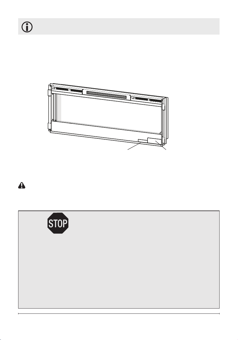
Quick Reference Guide
Figure 1
① The electrical information
regarding your electric replace can
be found on the rating label located
on the front of the unit, behind the
glass.
Before installation, please record your
replace's serial number below for
future reference.
② If you have any technical
questions or concerns regarding the
operation of your electric replace,
or require service contact customer
service.
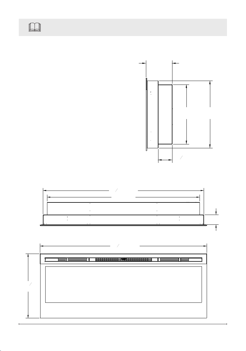
③ For dimensions of your replace,
refer to Figure 1.
3" (7.6 cm)
50
5
16
" (128 cm)
19
1
2
(49.5 cm)
46" (116 cm)
48
1
2
" (123 cm)
7"
(17.8 cm)
3
13
16
"
(9.7 cm)
18"
(45.7 cm)
16"
(40.6 cm)
7
Site Selection
Review and consider all of the fol-
lowing conditions for installation:
• Dimensions of the unit: 50
5
/
16
"
(128cm) x 19½"(49.5cm)
• Unit requires a minimum of two
wall studs in order to ensure a
secure installation
There are three possible mount-
ing methods:
• Surface mount (pg. 11);
• In-wall Recessed (pg. 13);
• Flush mount (pg. 14),
and any of these have the option
of being hard-wired or plugged
directly into the wall outlet.
CAUTION: Ensure installation
does not allow replace to be in
direct contact with building vapor
barrier or insulation and meets all
local building code.
!
NOTE 1: A 15 Amp, 120 Volt
circuit is required. A dedicated
circuit is preferred but not essen-
tial in all cases. A dedicated circuit
will be required if, after installa-
tion, the circuit breaker trips or
fuse blows on a regular basis
when the heater is operating. Ad-
ditional appliances on the same
circuit may exceed the current
rating of the circuit breaker.
Fireplace Installation
WARNING: Ensure the power
cord is not installed so that it
is pinched or against a sharp
edge and ensure that the
power cord is stored or secured
to avoid tripping or snagging to
reduce the risk of re, electric
shock or injury to persons.
Construction and electrical
outlet wiring must comply
with local building codes and
other applicable regulations to
reduce the risk of re, electric
shock and injury to persons.
WARNING: To reduce the risk
of re, do not store or use gaso-
line, or other ammable vapors or
liquids in the vicinity of the heater.
Grounding Instructions
This product must be grounded.
If it should malfunction or break-
down, grounding provides a path
of least resistance for electric
current to reduce the risk of
electric shock. This product is
equipped with a cord having an
equipment-grounding conductor
and a grounding plug. The plug
must be plugged into an appropri-
ate outlet that is properly installed
and grounded in accordance with
all local codes and ordinances.
DANGER: Improper connec-
8 www.dimplex.com
Fireplace Installation
tion of the equipment-grounding
conductor can result in a risk of
electric shock. Check with a quali-
ed electrician or serviceman if
you are in doubt as to whether the
product is properly grounded.
Do not modify the plug provided
with the product – if it will not t
the outlet, have a proper outlet
installed by a qualied electrician.
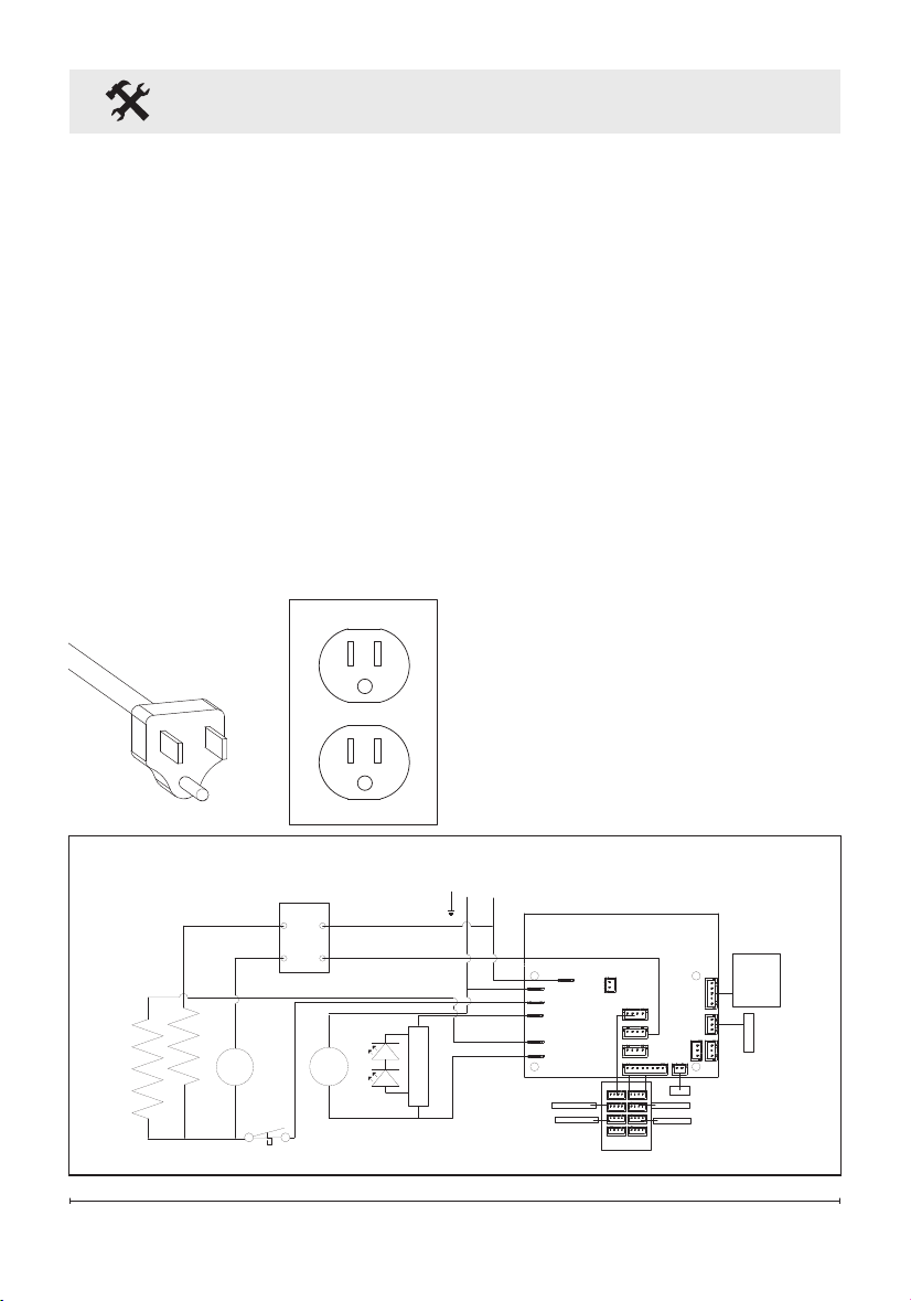
This product is for use on a
nominal 120-volt circuit and has
a grounding plug that looks like
the plug in Figure 3. Make sure
that the product is connected to
an outlet having the same con-
guration as the plug. No adapter
should be used with this product.
Installation
1. Select a location that is not
susceptible to moisture and
is away from drapes, furniture
and high trafc.
2. For ease of electrical hook up
you may wish to locate the
replace near an existing outlet
(for plug-in convenience) (refer
to NOTE 1).
3. Remove replace, front glass
and hardware from box and
remove all packaging materials
before installation.
4. Store the replace in a safe,
dry and dust free location until
you are ready to install the
Wiring
Figure 2
MOTOR
HEATER
NEUTRAL
FLAME COLOR
TOP LIGHT
LOG MEDIA NTC
GESTURE
DISPLAY
FAN
LINE
M
FLAME
MOTOR
LED CONTROL
BOARD
LED LIGHTS
NTC
MOTOR
HEATER
M
ELEMENT
ELEMENT
CUTOUT
THERMAL
BLOWER
MOTOR
LINE
N
LED LIGHTS
LED LIGHTS
LED LIGHTS
LED LIGHTS
SWITCH
BOARD
DISPLAY
BOARD
L1
120V~
60Hz
G
9
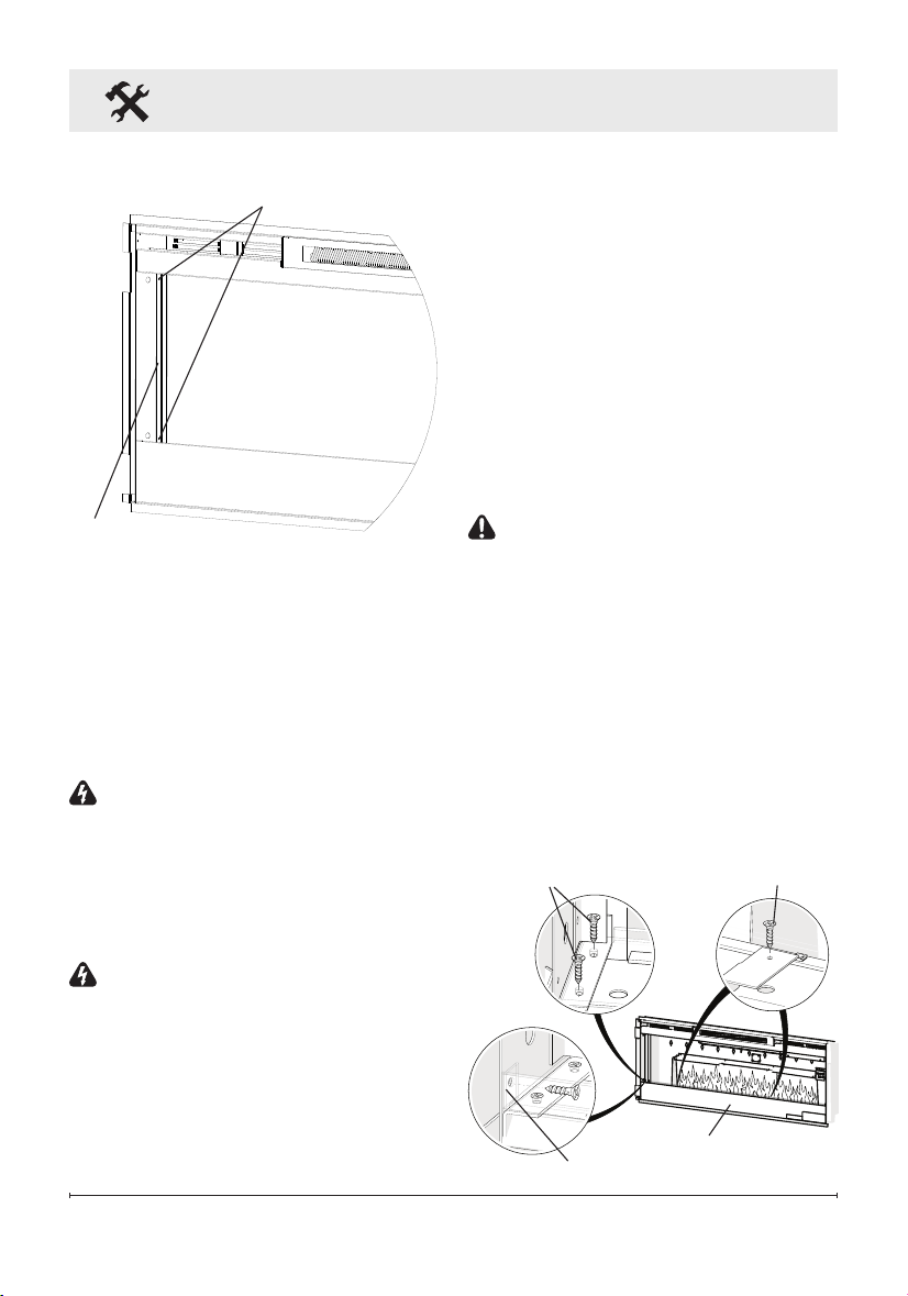
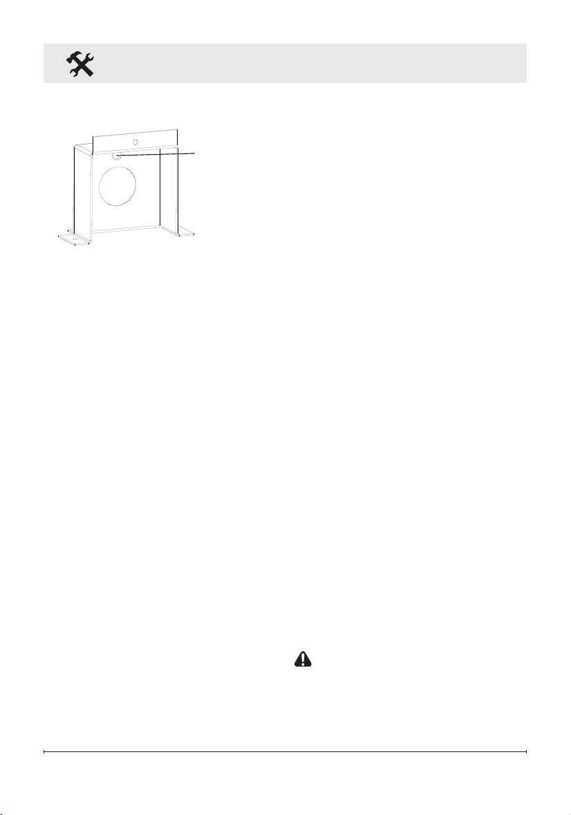
Figure 3
Partially
Reective Glass
Glass Bracket
Bracket Screws
replace.
Hardwire Installation
The replace is packaged with
a three prong plug installed for
plug-in convenience. Hard wiring
the replace is also an option for
any installation.
WARNING: Do not attempt
to wire your own new outlets
or circuits. To reduce the risk
of re, electric shock or in-
jury to persons, always use a
licensed electrician.
WARNING: Ensure that the
circuit on which the replace is
to be installed has the power
cut off at the service panel
until installation is complete.
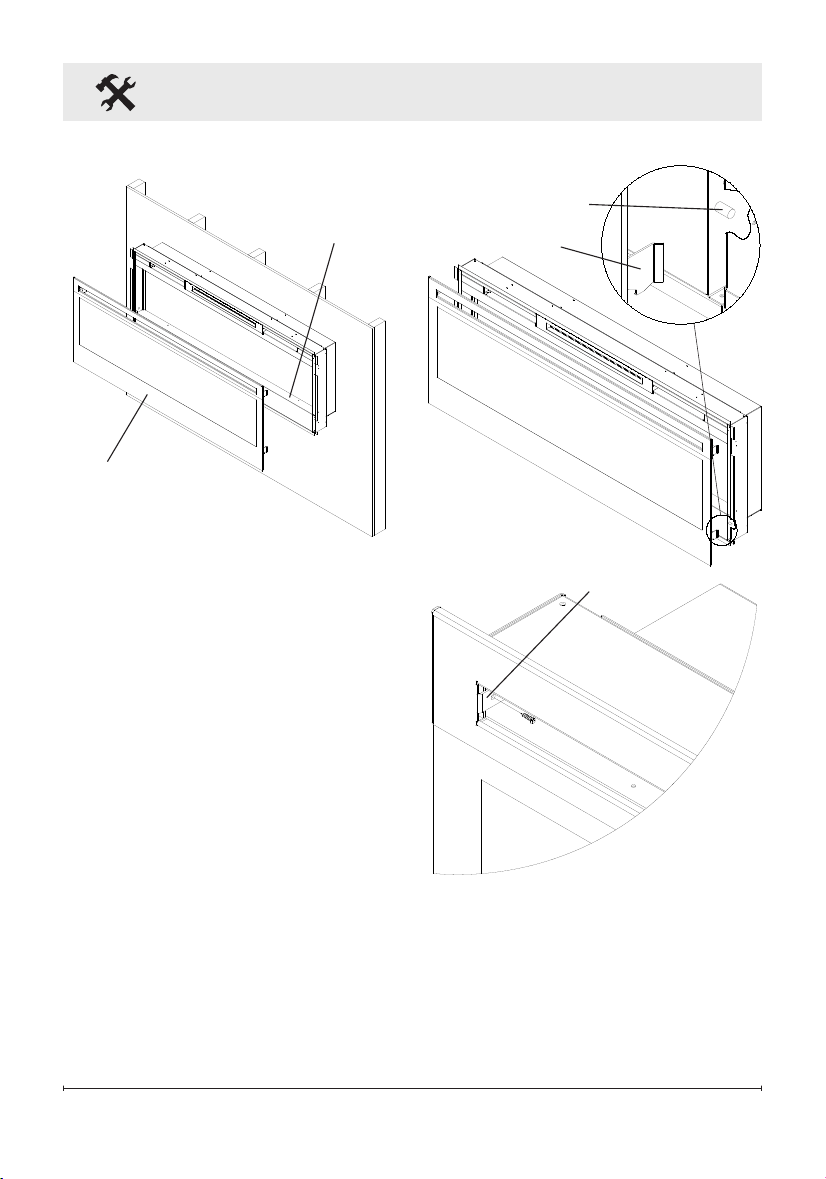
1. Remove the partially reective
glass from the replace:
Fireplace Installation
Front Panel
Front Panel tabs (2)
Acrylic Tray screws (4)
Metal Tray
Screws (4)
Figure 4
• Lay replace on its back.
• Remove two Phillips screws
from each of the two glass
brackets (Figure 3).
• Remove glass brackets.
• With one hand keeping pres-
sure on the partially reective
glass, tilt the replace upright
and slightly forward to allow
the partially reective glass to
fall out of the inside framing.
CAUTION: Partially reective
glass is not tempered. Do not
bump or drop the partially reec-
tive glass to avoid breakage and
personal injury.
• Remove partially reective
glass from replace.
2. Locate the power cord and
remove the 3 screws that at-
tach the metal bracket to the
10 www.dimplex.com
Black live
wires
Fireplace Installation
unit - one on the back of the
unit and two on the bottom.
(Figure 5)
3. From the front, remove the 2
Philips screws that fasten the
front panel tabs, tilt the panel
forward and lift off. (Figure 4)
4. Remove the 4 screws that
fasten the acrylic media tray
and the 2 screws that attach
the metal tray to the unit. The
metal tray cannot be removed
but will now allow the ability to
remove the electrical box.
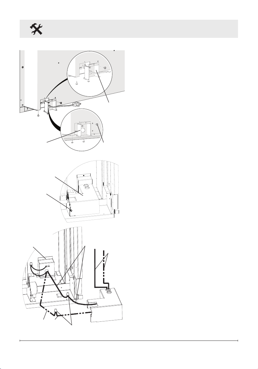
5. Remove the Phillips screw to
release the electrical box cov-
er in the bottom, right corner of
the replace (Figure 6).
6. Carefully slide the electrical
box to the right to release the
securing tabs, as wires are fed
through the strain reliefs on
the cover and are connected
within.
7. Unscrew the three wire con-
nectors inside the electrical
box and separate the wires
(Figure 7).
8. Pull the junction box and
power cord out the front of the
replace.
9. Replace removed junction
box cover with the supplied
Figure 7
Wires to
controls
Wire connectors
Junction
Box screw
Neutral wires
Figure 6
Electrical box
Screw
Figure 5
Screws
Hardwire
Bracket
Electrical
Cord
Bracket
11
Figure 8
Hole for
Ground Screw
Fireplace Installation
hard-wire cover replacement
(Figure 8) and install using
screws removed in step 2.
10. Leaving a minimum of 3 in.
(7.6 cm) of slack, route the
power supply through the hole
in the alternate junction box
cover and secure with a wire
clamp (not supplied).
11. Connect the black wire (live)
from the unit to the black wire
from the power supply using
one of the wire connectors
removed in step 5 (Figure 6).
12. Connect the black ribbed wire
(neutral) and white icker
motor wire from the unit to
the white wire from the power
supply using the second wire
connector from step 5 (Figure
6).
13. Attach green grounding wire
to hard wire cover cover with
provided grounding screw.
Place wire in-between screw
and lock washer and tighten.
14. Reposition the electrical box
cover over the wires and con-
nectors and attach to replace
chassis using the screw
removed in step 3.
15. Carefully reinsert partially re-
ective glass into replace and
anchor in place using glass
brackets and screws removed
in step 1.
16. Refer to Front Glass Installa-
tion section, for nal installa-
tion procedures.
For Bathroom Use
If this unit is installed in a bath-
room it must be protected by a
GFI receptacle or circuit. If recep-
tacle is used it must be readily
accessible.
This electrical applicance is not
watertight. To prevent electrical
shock, it must be installed as to
prevent water from entering unit.
This must be installed away from
showers, tubs, etc. Never locate
replace where it may fall into a
bathtub or other water container.
Surface Installation
CAUTION: Two people may
be required for various steps
of this procedure.
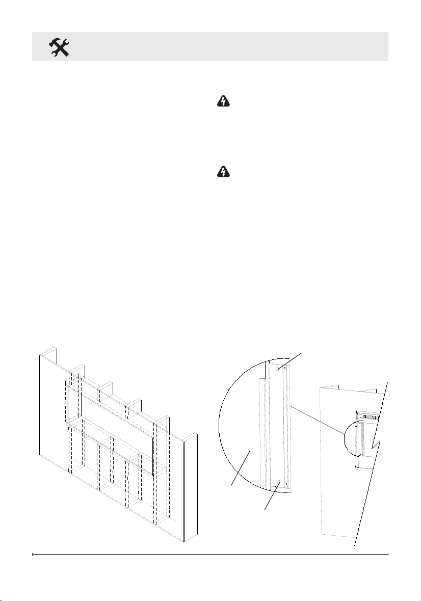
1. Choose a location which has
12 www.dimplex.com
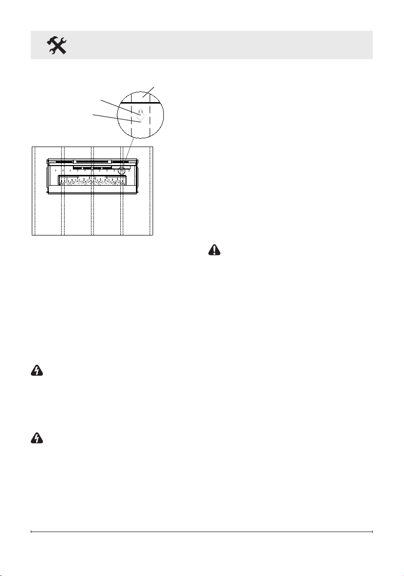
Figure 9
Key-hole
Wall stud
Permanent
mounting hole
a minimum of two wall studs
available for mounting.
2. Choose your method of sup-
plying power to the unit:
• Plug in to an existing outlet or
install an outlet nearby.
• Hard wire the replace. Follow
the hard wiring instructions on
page 9.
WARNING: Do not attempt
to wire your own new outlets or
circuits. To reduce the risk of re,
electric shock or injury to persons,
always use a licensed electrician.
WARNING: Ensure that the
circuit on which the replace is to
be installed has the power cut off
at the service panel until installa-
tion is complete.
3. Remove the partially reective
Fireplace Installation
glass from the replace:
• Lay replace on its back.
• Remove two Phillips screws
from each of the two glass
brackets (Figure 3, page 9).
• Remove glass brackets.
• With one hand keeping pres-
sure on the partially reective
glass, tilt the replace upright
and slightly forward to allow
the partially reective glass to
fall out of the inside framing.
CAUTION: Partially reective
glass is not tempered. Do not
bump or drop the partially reec-
tive glass to avoid breakage and
personal injury.
• Remove partially reective
glass from replace.
4. Position the replace on a wall
at the position where it will
be mounted (Figure 9). Use a
bubble level (one is supplied)
to ensure that replace is level
on the wall.
5. Ensuring that at least two
key-holes line up with a wall
stud (key-holes are spaced
at 4 in. (10.2 cm) centers),
mark the location of four screw
locations on the wall (through
key-holes).
13
Fireplace Installation
6. Remove fireplace from wall
and store in a safe place away
from traffic.
7. Where marked screw locations
do not line up with a wall stud,
insert (screw in) one of the two
supplied wall anchors (predrill
if required). Repeat if only two
screws line up with a wall stud.
8. Screw all four supplied #8,
1½ in. (3.8 cm) square head
mounting screws and wash-
ers into the wall and/or wall
anchors leaving ¼ in. (6.5 mm)
of thread.
9. Align chosen key-holes with
screws and hang replace on
the wall. Screw heads and
washers will t through key-
holes and replace will slide
down into place (screws will
slide into narrow part of key-
holes).
10. Tighten all four mounting
screws down on replace
chassis.
11. Screw the two supplied #8
square head screws through
two of the permanent mount-
ing holes which align with a
wall stud.
12. Carefully replace and install
partially reflective glass and
glass brackets using screws
from step 1.
13. Refer to Front Glass Installa-
tion section for nal installation
procedures.
In-wall Recessed Installation
- 2x4 Framing
CAUTION: Two people may
be required for various steps
of this procedure.
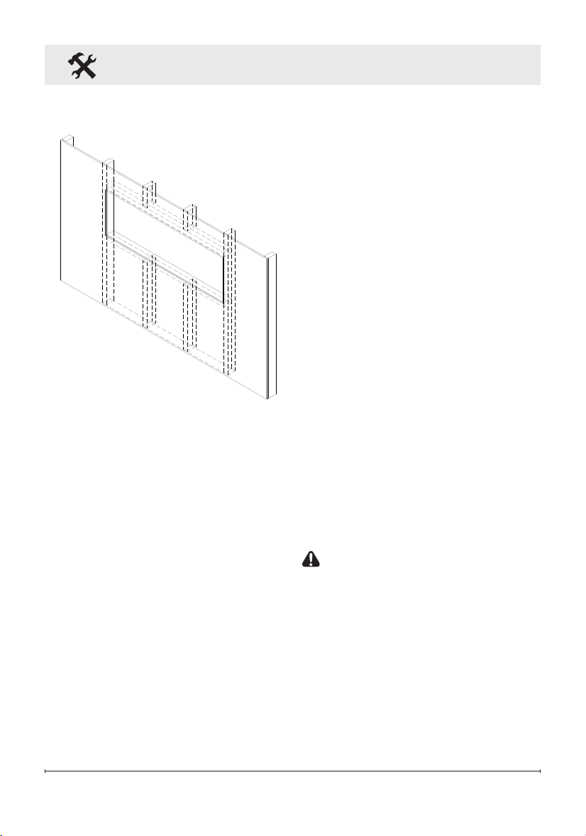
1. Prepare a wall with a framed
opening of 46 ½ in. (118.1 cm)
wide x 16 ½ in. (42 cm) high
(Figure 10).
!
NOTE: The sizing has allowed
for 1/4 in. (6.4 mm) around the
replace insert for ease of instal-
Figure 10
2 x 4 Framing
14 www.dimplex.com
Fireplace Installation
Figure 12
Mounting
hole
lation. This replace does not
require any additional venting.
2. Choose your method of sup-
plying power to the unit:
• Plug in (you may run the pow-
er cord out of the framed wall
opening to an existing outlet
or install an outlet on a nearby
wall stud within the wall).
• Hard wire the replace (rec-
ommended). Follow the hard
wiring instructions on page 9.
WARNING: Do not attempt
to wire your own new outlets or
circuits. To reduce the risk of re,
electric shock or injury to persons,
always use a licensed electrician.
WARNING: Ensure that the
circuit on which the replace is to
be installed has the power cut off
at the service panel until installa-
tion is complete.
3. Lift replace and insert into
opening (Figure 11).
4. Use bubble level (supplied) to
level the replace within the
framing. Adjust as required.
5. Drive four supplied mount-
ing screws through the four
mounting holes located in
each corner of the replace
chassis, into wall studs (Figure
12).
6. Refer to Front Glass Installa-
tion section for nal installation
procedures.
Flush Mounted Installation -
2x8 Framing
CAUTION: Two people may
be required for various steps
of this procedure.
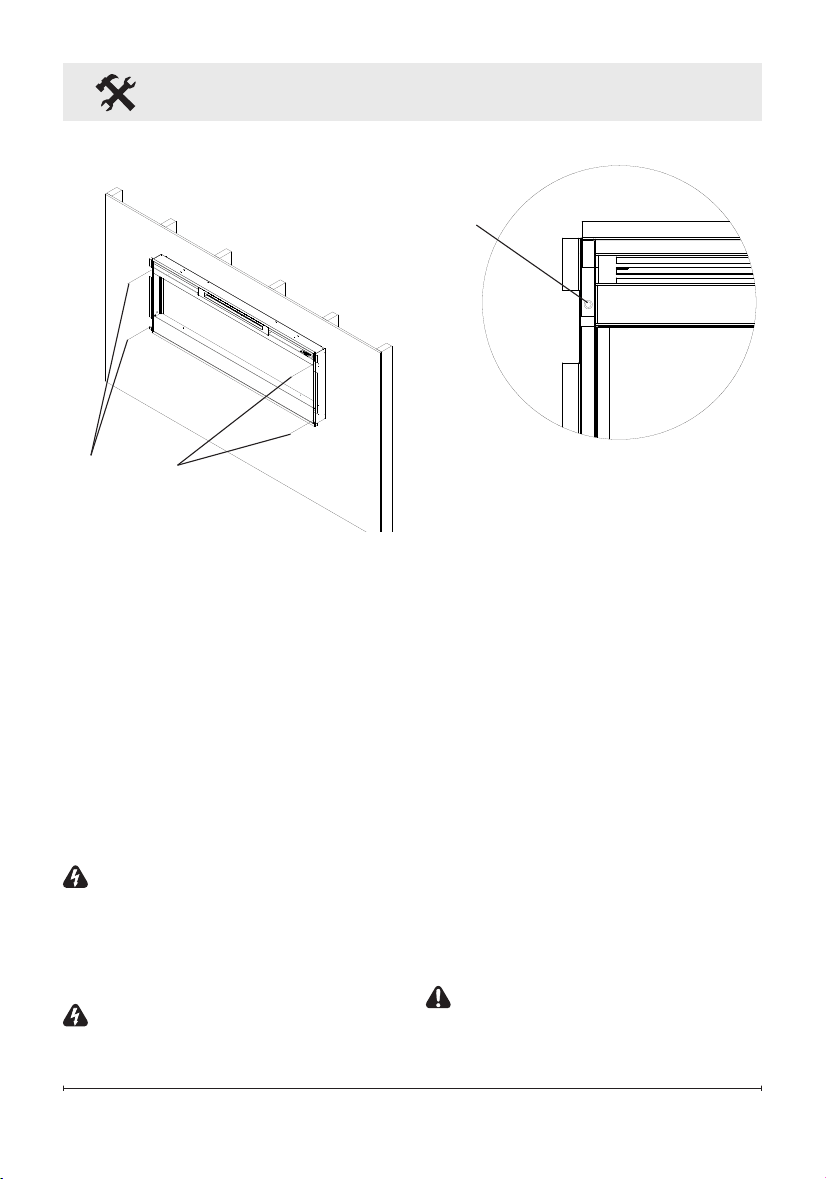
Figure 11
Mounting
holes
15
Figure 13
2 x 8 Framing
Fireplace Installation
1. Prepare a wall with a framed
opening of 49 in. (124.5 cm)
wide x 18½ in. (47 cm) high
(Figure 13).
!
NOTE: The sizing has al-
lowed for 1/4” (6.4mm) around the
replace insert for ease of instal-
lation. This replace does not
require any additional venting.
2. Choose your method of sup-
plying power to the unit:
• Plug in (you may run the pow-
er cord out of the framed wall
opening to an existing outlet
or install an outlet on a nearby
wall stud within the wall).
• Hard wire the replace (rec-
ommended). Follow the hard
wiring instructions on page 9.
WARNING: Do not attempt
to wire your own new outlets or
circuits. To reduce the risk of re,
electric shock or injury to persons,
always use a licensed electrician.
WARNING: Ensure that the
circuit on which the replace is to
be installed has the power cut off
at the service panel until installa-
tion is complete.
3. Lift replace and insert into
opening. The replace's
mounting trim should be ush
against the wall (Figure 14).
4. Use bubble level (supplied) to
level the replace within the
framing. Adjust as required.
Figure 14
Mounting hole
Mounting hole
Wall
surface
16 www.dimplex.com
Fireplace Installation
Figure 17
Tab
Figure 16
Hooks (4)
Mounts (4)
5. Drive four supplied mount-
ing screws through the four
mounting holes located on the
inside surface of the replace
chassis, into wall studs (Figure
14).
6. Refer to Front Glass Installa-
tion section for nal installation
procedures.
Front Glass Installation
1. Evenly distribute supplied
glass rock on the front tray of
the fireplace (Figure 15).
2. Carefully mount front glass as-
sembly so that the front glass
hooks (4) hang on the front
glass mounts on the fireplace
(4) (Figure 16).
3. Use the supplied two Phillips
sheet metal screws to fasten
the glass assembly tabs to the
fireplace (Figure 17).
4. If unit is not hard-wired, plug
fireplace into a 15 Amp, 120
Volt outlet (refer to NOTE 1).
Figure 15
Front tray
Front glass
assembly
17
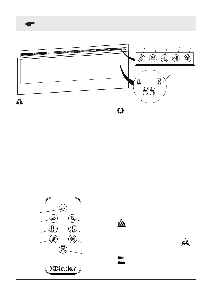
Operation
Figure 18
WARNING: This electric re-
box must be properly installed
before it is used.
The unit can be controlled by
either the manual controls which
are located on the upper right of
the replace or the remote (Figure
18 & 19).
The replace is supplied with an
IR multifunction remote control.
!
NOTE: To operate correctly,
the remote control must be point-
ed towards the Floating Display
TM
.
A. Standby
Turns the unit On and Off.
→ Activated by pressing the
Standby button on the remote
or the unit.
• The unit will turn on with the
same functions that it was set
to when it was turned Off and
the intake temperature will be
indicated on the On Screen
Display.
!
NOTE: When any button is
pressed the intake tempera-
ture will be displayed on the On
Screen Display for 5 seconds.
B. Flame Effects
Turns the ame effect On and Off.
→ Activated by pressing the
button on the remote.
C. Heat ON/OFF
Cycles the unit sequentially
Figure 19
A
D
B C
E
G
H
F
A C D E
F
Floating
Display
TM
18 www.dimplex.com
Operation
through the 3 settings: Low Heat,
High Heat and Off.
→ Activated by pressing the
button on the unit or the re-
mote.
• Indicated by the icon and
the intake temperature being
displayed on the On Screen
Display, for 5 seconds before
turning off.
!
NOTE: After the heater is
switched off, there is a 60 second
fan delay, where the fan will con-
tinue running before turning off.
!
NOTE: The unit can be oper-
ated in Heat Only Mode. When
the unit is only running with the
heater, the icon will con-
tinuously be displayed on the On
Screen Display.
!
NOTE: The heater may emit
a slight, harmless odor when rst
used. This odor is a normal condi-
tion caused by initial heating of
internal heater parts and will not
occur again.
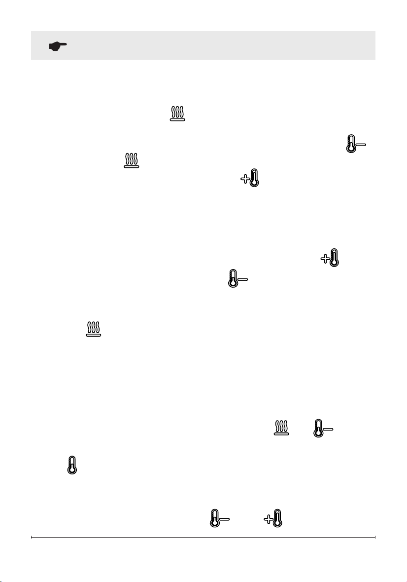
D & E.
Thermostat Controls
Adjusts the temperature set point
to your individual requirements.
Once the desired set temperature
is reached the heater will turn off.
The heater will cycle on and off
to maintain the desired set tem-
perature. The default temperature
setting is 72°F (22°C).
→ Adjusted by pressing the
to decrease the setpoint and
the to increase the setpoint
on the unit or the remote.
• The On Screen Display will in-
dicate the temperature setpoint
as it is adjusted.
!
NOTE: Holding the and
the
buttons down for two
seconds, on the unit, will change
the temperature from °C to °F, or
vice versa.
Disable Heat
If desired, depending on the sea-
son, the heater on the unit can be
disabled. The unit will operate in
the same fashion, with remainder
of the controls.
Pressing the and buttons
on the unit at the same time and
holding for 2 seconds will disable
and enable the heater.
!
NOTE: When the heater has
been disabled and either the
or the is pressed the On
19
Operation
Screen Display will indicate "--".
F. Color Themes
Different presets of ambient light-
ing color combinations contained
in the unit.
→ Changed by repeatedly press-
ing the corresponding button
on the remote or the unit.
• Cycles through the different
preset ambient lighting settings
of the unit, this includes differ-
ent combinations of colours
of the ame base and media
lighting.
!
NOTE: The last theme of the
cycle is a prism where the unit cy-
cles through a variety of colours.
Pressing the
button stops the
cycling and holds the unit on the
preferred color, indicated by a "U"
- Unfreeze or a "F" - Freeze on
the display.
G.
Brightness
Changes the brightness of the
lights in the unit.
→ Adjusted by repeatedly press-
ing the corresponding button
on the remote.
• Indicated by the second
digit on the Floating Display™
changing to show: "H" (high),
and "L" (low).
H. Sleep Timer
The Sleep Timer can be set to
automatically shut off the replace
after a preset time (from 30 min-
utes to 8 hours).
→ To set the timer press the timer
button on either the remote or
the unit, repeatedly, until the
desired time is displayed.
• The On Screen Display will
display the different times as it
is adjusted. Once the timer has
begun, pressing the button
will display the time remaining
before the unit turns Off.
!
NOTE: The Sleep Timer can
be cancelled at any time by
pressing the button repeat-
edly until the sleep timer displays
nothing.
Resetting the Temperature
Cutoff Switch
Should the heater overheat, an
automatic cut out will turn the
heater off and it will not come
back on without being reset. It
can be reset by unplugging the
unit and waiting 5 minutes before
plugging the unit back in.

20 www.dimplex.com
Operation
CAUTION: If you need to con-
tinuously reset the heater, unplug
the unit and call technical support
at 1-888-346-7539.
Remote Control Battery
Replacement
To replace the battery:
1. Slide battery cover open on
the remote control.
2. Correctly install one 3 Volt
(CR2032 [longer life] or
CR2025) battery in the battery
holder.
3. Close the battery cover.
Battery must be recycled
or disposed of properly.
Check with your Local
Authority or Retailer for recycling
advice in your area

21
Maintenance
WARNING: Disconnect power
and allow heater to cool before
attempting any maintenance or
cleaning to reduce the risk of
re, electric shock or damage
to persons.
!
NOTE: The replace should
not be operated with an accumu-
lation of dust or dirt on or in the
unit, as this can cause a build up
of heat and eventual damage. For
this reason the heater must be
inspected regularly, depending
upon conditions and at least at
yearly intervals.
Partially Reective Glass
Cleaning
The partially reective glass is
cleaned in the factory during the
assembly operation. During ship-
ment, installation, handling, etc.,
the partially reective glass may
collect dust particles; these can
be removed by dusting lightly with
a clean dry cloth.
To remove ngerprints or other
marks, the partially reective
glass can be cleaned with a damp
cloth. The partially reective glass
should be completely dried with
a lint free cloth to prevent water
spots. To prevent scratching, do
not use abrasive cleaners.
Fireplace Surface Cleaning
Use only a damp cloth to clean
painted surfaces of the replace.
Do not use abrasive cleaners.
Servicing
Except for installation and clean-
ing described in this manual,
an authorized service repre-
sentative should perform any
other servicing.

22 www.dimplex.com
Products to which this limited warranty
applies
This limited warranty applies to your newly
purchased Dimplex electric replace. This
limited warranty applies only to purchases
made in any province of Canada except
for Yukon Territory, Nunavut, or Northwest
Territories or in any of the 50 States of the
USA (and the District of Columbia) except
for Hawaii and Alaska. This limited war-
ranty applies to the original purchaser of
the product only and is not transferable.
Products excluded from this limited war-
ranty
Light bulbs are not covered by this limited
warranty and are the sole responsibility of
the owner/purchaser. Products purchased
in Yukon Territory, Nunavut, Northwest
Territories, Hawaii, or Alaska are not cov-
ered by this limited warranty. Products
purchased in these States, provinces, or
territories are sold AS IS without warranty
or condition of any kind (including, without
limitation, any implied warranties or condi-
tions of merchantability or tness for a
particular purpose) and the entire risk of
as to the quality and performance of the
products is with the purchaser, and in the
event of a defect the purchaser assumes
the entire cost of all necessary servicing
or repair.
What this limited warranty covers and for
how long
Products, other than replace surrounds
(mantels) and trims, covered by this
limited warranty have been tested and
inspected prior to shipment and, subject
to the provisions of this warranty, Dimplex
warrants such products to be free from
defects in material and workmanship for a
period of 2 years from the date of the rst
purchase of such products.
Dimplex replace surrounds (mantels) and
trims covered by this limited warranty have
been tested and inspected prior to ship-
ment and, subject to the provisions of this
warranty, Dimplex warrants such products
to be free from defects in material and
workmanship for a period of 1 year from
the date of rst purchase of such products.
The limited 2 year warranty period for
products other than replace surrounds
(mantels) and trims and the limited 1 year
warranty period for replace surrounds
(mantels) and trims also applies to any
implied warranties that may exist under
applicable law. Some jurisdictions do not
allow limitations on how long an implied
warranty lasts, so the above limitation may
not apply to the purchaser.
What this limited warranty does not cover
This limited warranty does not apply to
products that have been repaired (except
by Dimplex or its authorized service rep-
resentatives) or otherwise altered. This
limited warranty does further not apply
to defects resulting from misuse, abuse,
accident, neglect, incorrect installation, im-
proper maintenance or handling, or opera-
tion with an incorrect power source.
What you must do to get service under
this limited warranty
Defects must be brought to the attention of
Dimplex Technical Service by contacting
Dimplex at 1-888-DIMPLEX
(1-888-346-7539), or 1367 Industrial
Road, Cambridge Ontario, Canada
N3H 4W3. Please have proof of purchase,
catalogue/model and serial numbers
available when calling. Limited warranty
service requires a proof of purchase of the
product.
What Dimplex will do in the event of a
defect
In the event a product or part covered by
this limited warranty is proven to be defec-
tive in material or workmanship during (i)
the 2 year limited warranty period for prod-
ucts other than replace surrounds (man-
tels) and trims, and (ii) the 1 year limited
warranty period for surrounds (mantels)
and trims, you have the following rights:
• Dimplex will in its sole discretion either
repair or replace such defective product
Warranty

23
or part without charge. If Dimplex is un-
able to repair or replace such product
or part, or if repair or replacement is
not commercially practicable or cannot
be timely made, Dimplex may, in lieu of
repair or replacement, choose to refund
the purchase price for such product or
part.
• Limited warranty service will be per-
formed solely by dealers or service
agents of Dimplex authorized to provide
limited warranty services.
• For products other than surrounds
(mantels) and trims, this 2 year lim-
ited warranty entitles the purchaser to
on-site or in-home warranty services.
Accordingly, Dimplex will be respon-
sible for all labour and transportation
associated with repairing or replacing
the product or part except as follows: (i)
charges which may be levied for travel
costs incurred to travel to the purchas-
er’s site where the product is located if
the purchaser’s site is beyond 30 miles
(48 km) from the closest service depot
of Dimplex’s dealer or service agent;
and (ii) the purchaser is solely respon-
sible for providing clear access to all
serviceable parts of the product.
• For surrounds (mantels) and trims, this
1 year limited warranty does not entitle
the purchaser to on-site or in-house
warranty services. The purchaser is
responsible for removal and transpor-
tation of the surrounds (mantels) and
trims (and any repaired or replacement
product or part) to and from the autho-
rized dealer’s or service agent’s place
of business. On-site or in-home services
for surrounds (mantels) and trims may
be performed at the purchaser’s spe-
cic request and expense at Dimplex’s
then current rates for such services.
Dimplex will not be responsible for, and
this limited warranty shall not include,
any expense incurred for installation
or removal of the surrounds (mantels)
or trims or any part thereof (or any re-
placement product or part) including,
without limitation, all shipping costs and
transportation costs to and from the
authorized dealer’s or service agent’s
place of business and all labour costs.
Such costs shall be the purchaser’s re-
sponsibility.
What Dimplex and its dealers and service
agents are also not responsible for:
IN NO EVENT WILL DIMPLEX, OR ITS
DIRECTORS, OFFICERS, OR AGENTS,
BE LIABLE TO THE PURCHASER OR
ANY THIRD PARTY. WHETHER IN CON-
TRACT, IN TORT, OR ON ANY OTHER
BASIS, FOR ANY INDIRECT, SPECIAL,
PUNITIVE, EXEMPLARY, CONSEQUEN-
TIAL, OR INCIDENTAL LOSS, COST,
OR DAMAGE ARISING OUT OF OR IN
CONNECTION WITH THE SALE, MAIN-
TENANCE, USE, OR INABILITY TO USE
THE PRODUCT, EVEN IF DIMPLEX
OR ITS DIRECTORS, OFFICERS, OR
AGENTS HAVE BEEN ADVISED OF
THE POSSIBILITY OF SUCH LOSSES,
COSTS OR DAMAGES, OR IF SUCH
LOSSES, COSTS, OR DAMAGES ARE
FORESEEABLE. IN NO EVENT WILL
DIMPLEX, OR ITS OFFICERS, DIREC-
TORS, OR AGENTS BE LIABLE FOR
ANY DIRECT LOSSES, COSTS, OR
DAMAGES THAT EXCEED THE PUR-
CHASE PRICE OF THE PRODUCT.
SOME JURISDICTIONS DO NOT ALLOW
THE EXCLUSION OR LIMITATION OF IN-
CIDENTAL OR CONSEQUENTIAL DAM-
AGES, SO THE ABOVE LIMITATION OR
EXCLUSION MAY NOT APPLY TO THE
PURCHASER.
How State and Provincial law apply
This limited warranty gives you specic
legal rights, and you may also have other
rights which vary from jurisdiction to juris-
diction. The provisions of the United Na-
tions Convention on Contracts for the Sale
of Goods shall not apply to this limited
warranty or the sale of products covered
by this limited warranty.
Warranty

24 www.dimplex.com
© 2016 Dimplex North America Limited
Dimplex North America Limited
1367 Industrial Road
Cambridge ON
Canada N3H 4W3
Technical Support
Technical and troubleshooting support, as well as a list of re-
placement parts can be found on
www.dimplex.com/customer_support.