Loading ...
Loading ...
Loading ...
2. If changingthedeckbelt withthe cuttingdeck stillinstalledon the
unit,lowerthe cuttingdeckto the lowestcutting position.Remove
the deck beltfromaroundthe unit'sPTOdrive pulleyas shownin
Fig.31.Simplyrollone sideof the beltoff of the pulleyandthen
workit off the pulleyby continuingaroundthe pulleyuntilthe belt
is off of the pulley.
3. Pull the belttowardsthe rearof the unit, pullingit throughandout
of the belt keeperbracket,shownin Fig.31.
4. Removethedeckbelt coverby removingthe threehexboltsthat
secureit. SeeFig. 35.
f
.
/
Figure 35
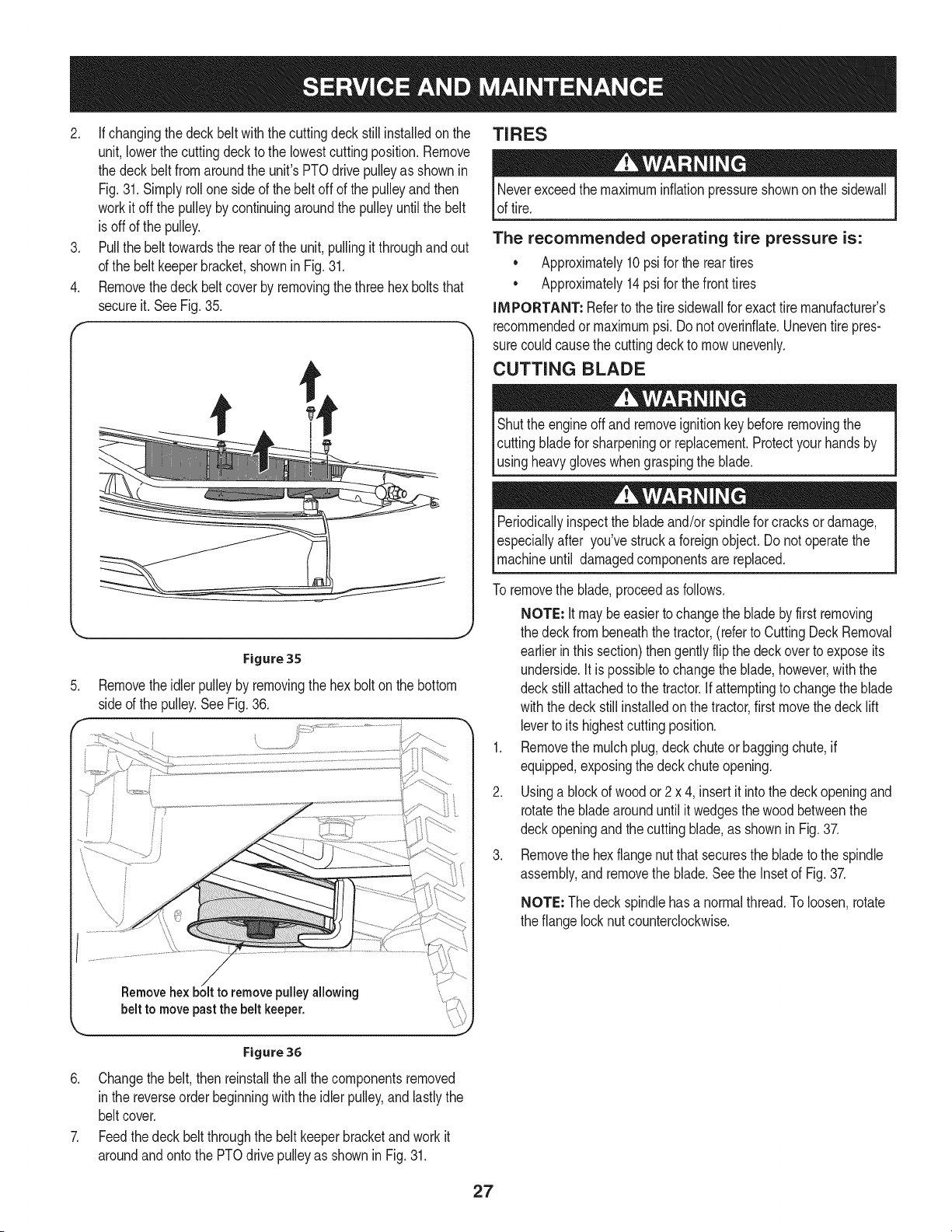
Removetheidler pulleyby removingthe hex boltonthe bottom
sideof the pulley.SeeFig.36.
pulleyallowing
belt to move pastthe belt keeper.
TIRES
Neverexceedthe maximuminflationpressureshownon the sidewall
of tire.
The recommended operating tire pressure is:
• Approximately10psifor the reartires
• Approximately14psi for thefront tires
IMPORTANT: Referto the tire sidewallfor exacttire manufacturer's
recommendedormaximumpsi.Donot overinfiate.Uneventirepres-
surecouldcausethe cuttingdeckto mowunevenly.
CUTTING BLADE
Shutthe engineoff and removeignitionkey beforeremovingthe
cuttingbladefor sharpeningor replacement.Protectyourhandsby
_usng heavygoves whengraspngthe bade.
Periodicallyinspectthe bladeand/or spindlefor cracksor damage,
especiallyafter you'vestrucka foreignobject.Do notoperatethe
machineuntil damagedcomponentsare replaced.
To removethe blade,proceedas follows.
NOTE: It maybe easiertochangethe bladebyfirst removing
the deck from beneaththetractor,(referto CuttingDeckRemoval
earlierinthis section)thengentlyflipthe deckoverto exposeits
underside.Itis possibleto changethe blade,however,withthe
deckstill attachedto the tractor.If attemptingto changethe blade
withthe deck still installedonthe tractor,firstmovethe deck lift
leverto itshighestcuttingposition.
1. Removethe mulchplug,deck chute or baggingchute,if
equipped,exposingthe deckchuteopening.
2. Usinga blockof woodor 2 x 4, insertit intothe deckopeningand
rotatethe bladearounduntilit wedgesthe woodbetweenthe
deckopeningand the cuttingblade,as shownin Fig.37.
3. Removethe hexflangenut that securesthe bladeto the spindle
assembly,and removethe blade.Seethe Insetof Fig.37.
NOTE: Thedeckspindlehasa normalthread.Toloosen,rotate
the flangelocknut counterclockwise.
Figure 36
6. Changethe belt,thenreinstallthe all the componentsremoved
in the reverseorderbeginningwith theidlerpulley,andlastlythe
beltcover.
7. Feedthedeck beltthroughthe belt keeperbracketand workit
aroundandontothe PTOdrivepulleyas shownin Fig.31.
27
Loading ...
Loading ...
Loading ...