perator's
£RnFrSMRN°
REAR ENGINE RiDiNG MOWER
6 Speed, Shift-on=the=Go
30" Deck
Model No. 247.25000
• Espanol, P. 69
This product has a low emission engine which operates differently
from previously built engines. Before you start the engine, read and
understand this Operator's Manual.
Before using this equipment,
read this manual and follow
all safety rules and operating
instructions.
For answers to your questions about
this product, Call:
1-800=659=5917
Craftsman Tractor Help Line
7 am = 7 pm CT, Mort. =Sun.
Sears Brands Management Corporation, Hoffman Estates, IL 60179 U.S.A.
Visit our website: www.craftsman.com FormNo.769-07597A
(March22,2012)
Warranty Statement .......................................................... 2
Safety Instructions ............................................................ 3
Slope Gauge ..................................................................... 9
Assembly ......................................................................... 10
Operation ........................................................................ 15
Service and Maintenance .............................................. 21
Off-Season Storage ........................................................ 32
Trou bleshooting .............................................................. 33
Labels ............................................................................. 34
Parts List ......................................................................... 35
Espa_ol ............................................................................ 69
Service Numbers ............................................. Back Cover
CRAFTSMAN FULL WARRANTY
FORTWOYEARSfromthe date of purchase,all non-expendablepartsof thisridingequipmentarewarrantedagainstany defectsinmaterial
or workmanship.A defectivenon-expendablepart will receivefree in-homerepairor replacementif repairisimpossible.
FORFIVEYEARSfromthe dateof purchase,the frameandfrontaxleof this ridingequipmentarewarrantedagainstanydefectsinmaterialor
workmanship.A defectiveframeor frontaxle will receivefreein-homerepairor replacementif repairis impossible.
FOR90 DAYSfromthe dateof purchase,the battery(an expendablepart)of this ridingequipmentis warrantedagainstanydefectsin material
or workmanship(ourtestingprovesthat it will not holda charge).A defectivebatterywill receivefreein-homereplacement.
ADDITIONALLIFETIMELIMITEDWARRANTYon CASTIRON FRONTAXLE(if equipped)
FORAS LONGASIT IS USEDby the originalownerafterthe fifth yearfromthedate of purchase,the cast ironfrontaxle (ffequipped)of
this ridingequipmentiswarrantedagainstany defectsinmaterialorworkmanship.With proofof purchase,a defectivecast ironfrontaxle will
receivefree in-homereplacement.
WARRANTYSERVICE
Forwarrantycoveragedetailsto obtainfree repairor replacement,call 1-800-659-5917or visit theweb site:www. craftsman.corn
Inallcasesabove,if partrepairor replacementis impossible,theridingequipmentwillbe replacedfreeof chargewiththe sameoranequivalentmodel.
All of the abovewarrantycoverageis voidif this ridingequipmentis ever usedwhileprovidingcommercialservicesor if rentedto another
person.
This warrantycovers ONLYdefects in material and workmanship. Warranty coverage does NOTinclude:
• Expendableparts(exceptbattery)thatcan wearout fromnormaluse withinthe warrantyperiod,includingbutnot limitedto blades,
sparkplugs,air cleaners,belts,andoilfilters.
• Standardmaintenanceservicing,oilchanges,ortune-ups.
• Tire replacementor repaircausedby puncturesfromoutsideobjects,suchas nails,thorns,stumps,or glass.
• Tire or wheel replacementor repairresultingfromnormalwear,accident,or improperoperationormaintenance.
• Repairsnecessarybecauseof operatorabuse,includingbutnot limitedto damagecausedbytowingobjectsbeyondthe capabilityof
the ridingequipment,impactingobjectsthat bendthe frame,axle assemblyor crankshaft,orover-speedingtheengine.
• Repairsnecessarybecauseof operatornegligence,includingbut not limitedto, electricaland mechanicaldamagecaused by
improperstorage,failureto use the propergradeandamountof engineoil, failureto keepthedeckclear of flammabledebris,or
failureto maintainthe ridingequipmentaccordingto the instructionscontainedin the operator'smanual.
• Engine(fuelsystem)cleaningor repairscausedby fueldeterminedto becontaminatedoroxidized(stale).In general,fuel shouldbe
usedwithin30 daysof its purchasedate.
• Normaldeteriorationand wearof the exteriorfinishes,or productlabel replacement.
Thiswarrantygivesyou specificlegalrights,and you mayalso haveotherrightswhichvaryfromstateto state.
Sears Brands ManagementCorporation, Hoffman Estates, IL 60179
EngineOil: SAE30
Fuel: UnleadedGasoline
SparkPlug: F6RTC(951-10292)
© KCD IR LLC
Model Number:
Serial Number:
Dateof Purchase:
Recordthe modelnumber,serialnumber,
anddateof purchaseabove.
2
Thissymbolpointsout importantsafetyinstructionswhich,if not
followed,couldendangerthepersonalsafetyand/orpropertyof
yourselfandothers. Readandfollowall instructionsin thismanual
beforeattemptingto operatethismachine.Failureto complywith
theseinstructionsmayresultin personalinjury.Whenyou seethis
symbol,HEEDITSWARNING!
CALIFORNIA PROPOSITION 65
EngineExhaust,someof its constituents,andcertainvehicle
componentscontainoremit chemicalsknownto Stateof California
to cause cancerand birthdefectsor other reproductiveharm.
Batteryposts,terminals,and relatedaccessoriescontainleadand
leadcompounds,chemicalsknownto the Stateof Californiato
causecancerand reproductiveharm.Washhandsafterhandling.
Thismachinewasbuiltto be operatedaccordingto the safeopera-
tion practicesin this manual.As with anytypeof powerequipment,
carelessnessorerroron the partof the operatorcan resultin serious
injury.Thismachineis capableof amputatingfingers,hands,toes
andfeet and throwingdebris.Failureto observethe followingsafety
instructionscouldresultin seriousinjuryor death.
Your Responsibility--Restrict the useof thispowermachineto
personswho read,understandand follow thewarningsand instruc-
tionsin this manualand on the machine.
SAVE THESE INSTRUCTIONS!
GENERAL OPERATION
• Read,understand,and followall instructionson the machineand
in themanual(s)beforeattemptingto assembleand operate.
Keepthis manualina safe placefor futureand regularreference
andfor orderingreplacementparts.
• Befamiliarwithall controlsandtheir properoperation.Knowhow
to stop the machineanddisengagethemquickly.
• Neverallowchildrenunder14 yearsoldto operatethis machine.
Children14yearsoldand over shouldreadand understandthe
operationinstructionsandsafetyrulesin thismanualand should
betrainedandsupervisedbya parent.
• Neverallowadultsto operatethis machinewithoutproper
instruction.
• Tohelpavoidbladecontactor a thrownobjectinjury, keep
bystanders,helpers,childrenandpetsat least 75 feet fromthe
machinewhile it is in operation.Stopmachineif anyoneenters
the area.
• Thoroughlyinspectthe area wherethe equipmentis to be used.
Removeallstones,sticks,wire,bones,toys,and otherforeign
objectswhichcouldbe pickedupand thrownby the blade(s).
Thrownobjectscan causeseriouspersonalinjury.
• Planyour mowingpatternto avoiddischargeof materialtoward
roads,sidewalks,bystandersandthe like.Also,avoiddischarg-
ingmaterialagainstawall orobstructionwhichmaycause
dischargedmaterialto ricochetback towardthe operator.
• Alwayswear safetyglassesor safetygogglesduringoperation
andwhile performingan adjustmentor repairto protectyoureyes.
Thrownobjectswhichricochetcancause seriousinjuryto the
eyes.
• Wearsturdy,rough-soledworkshoesand close-fittingslacksand
shirts.Loosefittingclothesand jewelry canbe caughtin movable
parts.Neveroperatethismachineinbarefeetorsandals.
• Be awareof the mowerand attachmentdischargedirectionand
do not pointit at anyone.Donot operatethe mowerwithoutthe
dischargecoveror entiregrass catcherin its properplace.
Donot put handsor feetnearrotatingpartsor underthe cutting
deck. Contactwiththe blade(s)can amputatehandsand feet.
A missingor damageddischargecovercan causebladecontact
or thrownobjectinjuries.
• Stoptheblade(s)whencrossinggraveldrives,walks,or roads
andwhile notcuttinggrass.
• Watchfor trafficwhenoperatingnear or crossingroadways.This
machineis not intendedfor useon any public roadway.
• Donot operatethe machinewhile underthe influenceof alcohol
or drugs.
• Mowonly indaylightorgoodartificiallight.
Nevercarrypassengers.
• Disengageblade(s)beforeshiftinginto reverse.Backup slowly.
Alwayslookdownandbehindbeforeand while backingto avoida
back-overaccident.
3
• Slowdownbeforeturning.Operatethe machinesmoothly.Avoid
erraticoperationandexcessivespeed.
Disengageblade(s),setparkingbrake,stopengine and wait until
the blade(s)come to a completestopbeforeremovinggrass
catcher,emptyinggrass,uncloggingchute,removinganygrass or
debris,or makinganyadjustments.
Neverleavea runningmachineunattended.Alwaysturnoff
blade(s),setparkingbrake,stopengineand removekeybefore
dismounting.
Useextracare whenloadingorunloadingthe machineintoa
traileror truck.Thismachineshouldnot bedrivenupor down
ramp(s),becausethe machinecouldtip over,causingserious
personalinjury.The machinemustbe pushedmanuallyon
ramp(s)to loador unloadproperly.
Mufflerandenginebecomehotandcan causea burn.Do not
touch.
Checkoverheadclearancescarefullybeforedrivingunderlow
hangingtree branches,wires,dooropeningsetc.,wherethe
operatormaybe struckor pulledfrom the machine,whichcould
resultinseriousinjury.
Disengageallattachmentclutchesanddepressthe brakepedal
completelybeforeattemptingto start engine.
Yourmachineisdesignedto cutnormalresidentialgrassof a
heightnomorethan 10".Do not attemptto mowthroughunusually
tall,dry grass (e.g.,pasture)or piles of dry leaves.Drygrassor
leavesmaycontactthe engineexhaustand/or buildup on the
mowerdeckpresentinga potentialfire hazard.
Useonlyaccessoriesand attachmentsapprovedfor this machine
by the machinemanufacturer.Read,understandand followall
instructionsprovidedwiththe approvedaccessoryor attachment.
Fora list of approvedaccessoriesandattachments,call 1-800-
659-5917.
Dataindicatesthatoperators,age60 years and above,are
involvedin a largepercentageof ridingmower-relatedinjuries.
Theseoperatorsshouldevaluatetheirabilityto operatethe riding
mowersafelyenoughto protectthemselvesandothersfrom
seriousinjury.
If situationsoccurwhichare not coveredinthis manual,usecare
andgoodjudgment.
SLOPE OPERATION
Slopesarea majorfactorrelatedto loss of controlandtip-over
accidentswhichcan result in severeinjuryor death.All slopes require
extracaution.Ifyoucannotback up the slopeor if youfeel uneasyon
it, do not mowit.
Foryoursafety,use the SlopeGuide includedas partof this manual
to measureslopesbeforeoperatingthis machineon a slopedor hilly
area. If the slopeis greaterthan12 degreesas shownonthe Slope
Guide,do notoperatethis machineonthatareaor seriousinjurycould
result.
Do:
o
Mowupand down slopes,not across.Exerciseextremecaution
whenchangingdirectionon slopes.
• Watchfor holes,ruts,bumps,rocks,orother hiddenobjects.
Uneventerraincouldoverturnthe machine.Tallgrass can hide
obstacles.
Useslowspeed.Choosea lowenoughspeedsettingso that
you will nothaveto stopor shiftwhileon the slope.Tiresmay
lose tractionon slopeseventhoughthe brakesare functioning
properly.Alwayskeepmachinein gearwhen goingdownslopes
to take advantageof enginebrakingaction.
• Followthe manufacturer'srecommendationsfor wheelweightsor
counterweightsto improvestability.
Useextracarewithgrasscatchersor otherattachments.These
can changethe stabilityof the machine.
Keepallmovementon the slopesslowand gradual.Do not make
suddenchangesinspeedor direction.Rapidengagementor
brakingcouldcausethe frontof the machineto lift andrapidlyflip
overbackwardswhichcouldcauseseriousinjury.
• Avoidstartingorstoppingon a slope. If tires losetraction,disen-
gagethe blade(s)and proceedslowlystraightdownthe slope.
DoNot:
• Donot turnon slopesunlessnecessary;then, turnslowlyand
graduallydownhill,if possible.
• Donot mow neardrop-offs,ditchesor embankments.The mower
could suddenlyturnover if a wheelis overthe edgeof a cliff,
ditch,or if an edgecavesin.
• Donot try to stabilizethe machineby puttingyourfooton the
ground.
• Donot usea grass catcheron steepslopes.
• Donot mowon wet grass.Reducedtractioncouldcausesliding.
• Donot attemptto coastdownhill.Over-speedingmaycausethe
operatorto lose controlof the machineresultingin seriousinjury
or death.
• Donot tow heavypull behindattachments(e.g.loadeddumpcart,
lawn roller,etc.)on slopesgreaterthan5 degrees.Whengoing
down hill,the extraweighttendsto pushthe tractorandmay
causeyou to loosecontrol(e.g.tractormayspeedup, brakingand
steeringabilityare reduced,attachmentmayjack-knifeandcause
tractorto overturn).
4
CHILDREN
Tragicaccidentscanoccurifthe operatoris notalert to the presence
of children.Childrenare often attractedto the machineandthe mowing
activity.Theydo notunderstandthe dangers.Neverassumethat
childrenwill remainwhereyou last sawthem.
• Keepchildrenout of the mowingareaand inwatchfulcare of a
responsibleadultotherthanthe operator.
• Bealert and turnmachineoff ifa childentersthe area.
• Beforeand whilebacking,lookbehindanddownfor small
children.
Nevercarrychildren,evenwiththe blade(s)shut off.Theymay
fall off and be seriouslyinjuredorinterferewithsafemachine
operation.
• Useextremecarewhenapproachingblindcorners,doorways,
shrubs,treesor otherobjectsthatmayblockyourvisionof a child
whomay runintothe machine.
Toavoidback-overaccidents,alwaysdisengagethe cutting
blade(s)beforeshiftingintoReverse.If equipped,the "Reverse
CautionMode"(bladesoperatewhilemachineridesin reverse)
shouldnotbe usedwhenchildrenor othersarearound.
Keepchildrenawayfrom hotor runningengines.They cansuffer
burnsfroma hotmuffler.
• Removekeywhenmachineisunattendedto preventunauthorized
operation.
Neverallowchildrenunder14yearsof ageto operatethis machine.
Children14andovershouldreadandunderstandthe instructionsand
safeoperationpracticesinthis manualand on the machineandshould
betrainedandsupervisedbyan adult.
TOWING
Towonlywitha machinethathasa hitch designedfor towing.Do
not attachtowedequipmentexceptat the hitchpoint.
Followthe manufacturersrecommendationforweightlimitsfor
towedequipmentand towingon slopes.
Neverallowchildrenor othersin oron towedequipment.
Onslopes,theweightof thetowedequipmentmaycauselossof
tractionandloss of control.
Alwaysuseextra cautionwhentowingwith a machinecapableof
makingtightturns (e.g."zero-turn"ride-onmower). Makewide
turnsto avoidjack-knifing.
Travelslowlyandallowextradistanceto stop.
Do notcoastdownhill.
SERVICE
SafeHandlingof Gasoline
Toavoidpersonalinjuryorpropertydamageuse extremecarein
handlinggasoline.Gasolineisextremelyflammableand the vaporsare
explosive.Seriouspersonalinjurycanoccur whengasolineis spilled
on yourselforyour clotheswhich can ignite.Washyourskin and
changeclothesimmediately.
• Useonly anapprovedgasolinecontainer.
Neverfill containersinsidea vehicleoron a truckortrailer bed
witha plasticliner.Alwaysplacecontainerson the groundaway
fromyourvehiclebeforefilling.
Whenpractical,removegas-poweredequipmentfrom the truck
or trailerandrefueliton theground.If this isnot possible,then
refuelsuchequipmenton a trailerwith a portablecontainer,rather
than froma gasolinedispensernozzle.
Keepthe nozzleincontactwith the rim of the fueltankor
containeropeningat all timesuntilfuelingiscomplete.Donot use
a nozzlelock-opendevice.
Extinguishall cigarettes,cigars,pipesandothersourcesof
ignition.
• Neverfuel machineindoors.
Neverremovegascap or add fuelwhilethe engineis hotor run-
ning.Allowengineto coolat leasttwominutesbeforerefueling.
Neveroverfill fuel tank. Filltankto no morethan 1/2inchbelow
bottomof filler neckto allowspaceforfuel expansion.
• Replacegasolinecap andtightensecurely.
• If gasolineis spilled,wipeitoff the engineandequipment.Move
machineto anotherarea.Wait 5 minutesbeforestartingthe
engine.
• To reducefire hazards,keepmachinefree of grass,leaves,or
otherdebrisbuild-up.Cleanup oilor fuel spillageandremoveany
fuel soakeddebris.
• Neverstorethe machineor fuelcontainerinsidewherethere isan
openflame,sparkor pilotlight as ona waterheater,spaceheater,
furnace,clothesdryeror othergasappliances.
Allowa machineto coolat leastfive minutesbeforestoring.
GeneralService
• Neverrunanengineindoorsor ina poorlyventilatedarea. Engine
exhaustcontainscarbonmonoxide,an odorless,anddeadlygas.
• Beforecleaning,repairing,orinspecting,makecertainthe blade(s)
andall movingpartshavestopped.Disconnectthesparkplug wire
andgroundagainsttheengineto preventunintendedstarting.
• Periodicallycheckto makesurethe bladescometo complete
stopwithinapproximately(5) five secondsafteroperatingthe
bladedisengagementcontrol.If the bladesdonot stopwithinthe
thistimeframe,your machineshouldbe servicedprofessionally
by a Searsor otherqualifiedservicedealer.
• Checkbrakeoperationfrequentlyas it is subjectedto wearduring
normaloperation.Adjustand serviceas required.
• Checkthe blade(s)and engine mountingboltsat frequent
intervalsfor propertightness.Also, visuallyinspectblade(s)
for damage(e.g.,excessivewear,bent,cracked).Replacethe
blade(s)withtheoriginalequipmentmanufacturer's(O.E.M.)
blade(s)only,listedinthismanual.Useof parts whichdo not
meetthe originalequipmentspecificationsmaylead to improper
performanceandcompromisesafety!
• Mowerbladesare sharp.Wrapthe bladeor weargloves,anduse
extracautionwhen servicingthem.
• Keepall nuts,bolts,andscrewstight to besurethe equipmentis
insafeworkingcondition.
• Nevertamperwiththe safetyinterlocksystemor othersafety
devices.Checktheir properoperationregularly.
• Afterstrikinga foreignobject,stop the engine,disconnectthe
sparkplugwire(s)and groundagainstthe engine.Thoroughly
inspectthe machinefor anydamage.Repairthe damagebefore
startingandoperating.
• Neverattemptto makeadjustmentsor repairsto the machine
whilethe engineis running.
• Grasscatchercomponentsand the dischargecoverare subject
to wearanddamagewhich couldexposemovingparts or allow
objectsto bethrown.Forsafetyprotection,frequentlycheck
componentsand replaceimmediatelywithoriginalequipment
manufacturer's(O.E.M.)partsonly,listed in this manual.Useof
partswhichdo not meetthe originalequipmentspecificationsmay
leadto improperperformanceand compromisesafety!
• Do notchangethe enginegovernorsettingsor over-speedthe
engine.The governorcontrolsthe maximumsafeoperatingspeed
of the engine.
• Maintainor replacesafetyandinstructionlabels,as necessary.
• Observeproperdisposallawsand regulationsfor gas,oil, etc. to
protectthe environment.
• Accordingto the ConsumerProductsSafetyCommission(CPSC)
andthe U.S.EnvironmentalProtectionAgency(EPA),thisproduct
hasan AverageUsefulLifeof seven(7) years,or270 hours
of operation.At the endof the AverageUsefulLife,buya new
machineor havethe machineinspectedannuallyby a Searsor
otherqualifiedservicedealerto ensurethat allmechanicaland
safetysystemsare workingproperlyand notwornexcessively.
Failureto do so can resultinaccidents,injuriesordeath.
DO NOT MODIFY ENGINE
Toavoid seriousinjuryor death,do notmodifyengine in anyway.
Tamperingwiththe governorsettingcanlead to a runawayengineand
causeit to operateat unsafespeeds.Nevertamper with factorysetting
of enginegovernor.
NOTICE REGARDING EMISSIONS
Engineswhicharecertifiedto complywithCaliforniaandfederal
EPAemissionregulationsfor SORE(SmallOffRoadEquipment)are
certifiedto operateon regularunleadedgasoline,andmayinclude
the followingemissioncontrolsystems:EngineModification(EM)and
ThreeWay Catalyst(TWO)if so equipped.
SPARK ARRESTOR
Ifa sparkarrestoris used,it shouldbe maintainedin effectiveworking
orderby the operator.Inthe Stateof Californiatheaboveis required
by law (Section4442of the CaliforniaPublicResourcesCode).Other
statesmayhavesimilarlaws.Federallaws applyon federallands.
A sparkarrestorfor the mufflerisavailablethroughyournearestSears
PartsandRepairServiceCenter.
SAFETY SYMBOLS
Thispagedepictsanddescribessafetysymbolsthat mayappear
on thisproduct. Read,understand,and followall instructionson the
machinebeforeattemptingto assembleandoperate.
Thismachineisequippedwithan internalcombustionengineand
shouldnot beusedonor near anyunimprovedforest-covered,
brushcoveredor grass-coveredlandunlesstheengine'sexhaust
systemis equippedwith a sparkarrestormeetingapplicablelocalor
statelaws(if any).
6
...._ •
jZ
s j/
®
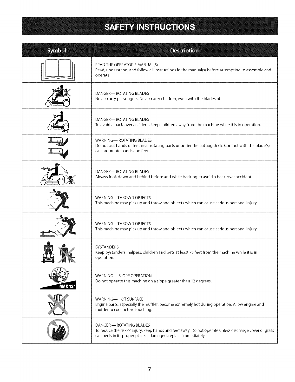
READ THE OPERATOR'S MANUAL(S)
Read, understand, and follow all instructions in the manual(s) before attempting to assemble and
operate
DANGER-- ROTATING BLADES
Never carry passengers. Never carry children, even with the blades off.
DANGER-- ROTATING BLADES
To avoid a back-over accident, keep children away from the machine while it is in operation.
WARNING-- ROTATING BLADES
Do not put hands or feet near rotating parts or under the cutting deck. Contact with the blade(s)
can amputate hands and feet.
DANGER-- ROTATING BLADES
Always look down and behind before and while backing to avoid a back-over accident.
WARNING--THROWN OBJECTS
This machine may pick up and throw and objects which can cause serious personal injury.
WARNING--THROWN OBJECTS
This machine may pick up and throw and objects which can cause serious personal injury.
BYSTANDERS
Keep bystanders, helpers, children and pets at least 75 feet from the machine while it is in
operation.
WARNING-- SLOPE OPERATION
Do not operate this machine on a slope greater than 12 degrees.
WARNING-- HOT SURFACE
Engine parts, especially the muffler, become extremely hot during operation. Allow engine and
muffler to cool before touching.
DANGER-- ROTATING BLADES
To reduce the risk of injury, keep hands and feet away. Do not operate unless discharge cover or grass
catcher is in its proper place. If damaged, replace immediately.
7
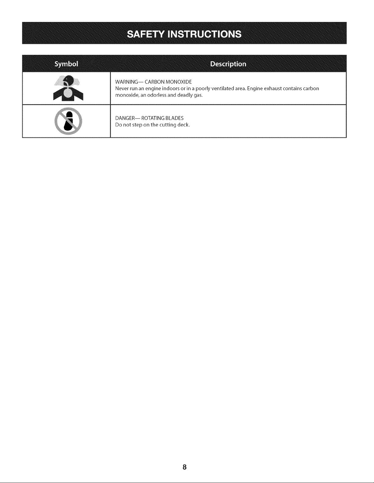
WARNING-- CARBON MONOXIDE
Never run an engine indoors or in a poorly ventilated area. Engine exhaust contains carbon
monoxide, an odorless and deadly gas.
DANGER-- ROTATING BLADES
Do not step on the cutting deck.
8
(OK)
iiiii!i!i!i!i!i!i!i! ! ! ! !iiiiii!ii!!i
X
(TO0 STEEP)
12° Slope
Figure1
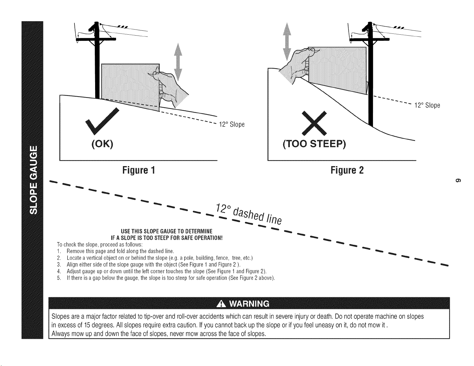
USETHiSSLOPEGAUGETODETERMINE
iFA SLOPEiSTOOSTEEPFORSAFEOPERATION!
Tocheckthe slope,proceedasfollows:
1. Removethis pageandfold alongthe dashedline.
2. Locateaverticalobjecton or behindthe slope(e.g.a pole,building,fence, tree, etc.)
3. Align eithersideof the slopegaugewith the object(SeeFigure1 and Figure2 ).
4. Adjust gaugeup or down untilthe leftcornertouchesthe slope(SeeFigure1 andFigure2).
5.
If thereis a gapbelowthe gauge,the slopeis too steepfor safeoperation(SeeFigure2 above).
Figure2
Slopes are a major factor related to tip-over and roll-over accidents which can result in severe injury or death. Do not operate machine on slopes
in excess of 15degrees. All slopes requireextra caution. If you cannot back up the slope or if you feel uneasy on it, do not mow it.
Always mow up and down the face of slopes, nevermow across the face of slopes.
Contentsof Crate
• One RidingMower
OneSteeringWheel/ShaftAssembly
OneRearHitchPlate
OneRidingMowerOperator'sManual
OneSeatAssembly
OneRearEngineCover
OneOil DrainSleeve
OneEngineOperator'sManual
OneSteeringPedestalCap
OneDischargeChuteAssembly
• One HardwarePack
• One ProductRegistrationCard
CONTENTS OF HARDWARE PACK
Beforebeginninginstallation,removeall the contentsfrom the crate
andall the hardwarefromthe pack from to makesureeverything
is present.Hardwareis listedbelow.Partnumbersare shownin
parentheses.
• Two5/16-18x 3/4" Screws-- HitchPlate(710-3008)
• Two5/16-18LockNuts-- HitchPlate(712-04063)
• Two1/4-15x 1"Screws-- EngineRearCover(710-1241)
• TwoShoulderBolts-- SeatPivotBracket(738-0140)
• Two5/16-18LockNuts-- SeatPivotBracket(712-04063)
• One 1/4-20x 3/4" Screw-- SteeringPedestal(710-0924)
• One 3/16HexKey-- SteeringShaft(710-05046)
RECOMMENDED TOOLS FOR ASSEMBLY
• 3/16" HexKey(includedin hardwarepack)
• 1/4" DriveRatchet
• 3/16"Wrench(or adjustablewrench)
• 3/8" Wrench(or adjustablewrench)
• 1/2" Wrench(or adjustablewrench)
• 5/8" Wrench(or adjustablewrench)
• 3/8" Socketwrench
• 1/2" Socketwrench
INSTALLING THE STEERING WHEEL ASSEMBLY
If the steeringwheelassemblyfor yourtractordidnot comealready
installed,followthe stepsbelow:
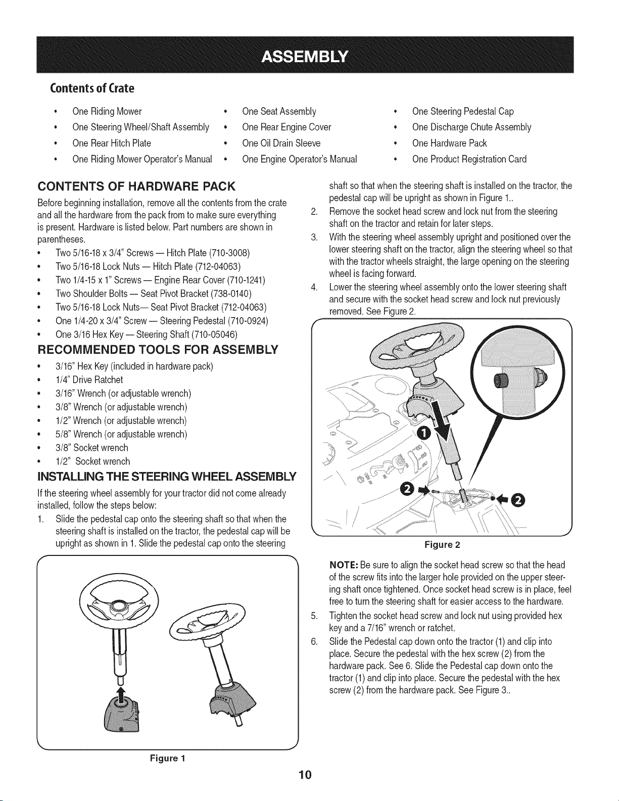
1. Slide the pedestalcap ontothe steeringshaftso thatwhenthe
steeringshaftis installedonthe tractor,the pedestalcap willbe
uprightas shownin 1.Slidethe pedestalcap ontothe steering
shaft so thatwhen the steeringshaft is installedon the tractor,the
pedestalcap will beuprightas shownin Figure1..
2. Removethe socketheadscrewandlocknut from the steering
shaft on the tractorand retainfor latersteps.
3. With the steeringwheelassemblyuprightand positionedoverthe
lowersteeringshafton the tractor,alignthe steeringwheelso that
withthe tractorwheelsstraight,the largeopeningonthe steering
wheelis facingforward.
4. Lowerthe steeringwheelassemblyontothe lowersteeringshaft
and securewiththe socketheadscrewand lock nut previously
removed.SeeFigure2.
.
6.
Figure 2
NOTE: Besureto alignthe sockethead screwsothatthe head
of the screwfits intothe largerhole providedon the uppersteer-
ing shaftoncetightened.Oncesocketheadscrewis in place,feel
free to turnthe steeringshaftfor easieraccess to the hardware.
Tightenthe sockethead screwand lock nutusingprovidedhex
keyanda 7/16"wrenchor ratchet.
Slidethe Pedestalcap downontothe tractor(1)andclip into
place.Securethe pedestalwiththe hex screw(2) from the
hardwarepack.See6. Slidethe Pedestalcapdownonto the
tractor(1) andclip intoplace.Securethe pedestalwiththe hex
screw(2) from the hardwarepack.SeeFigure3..
Figure 1
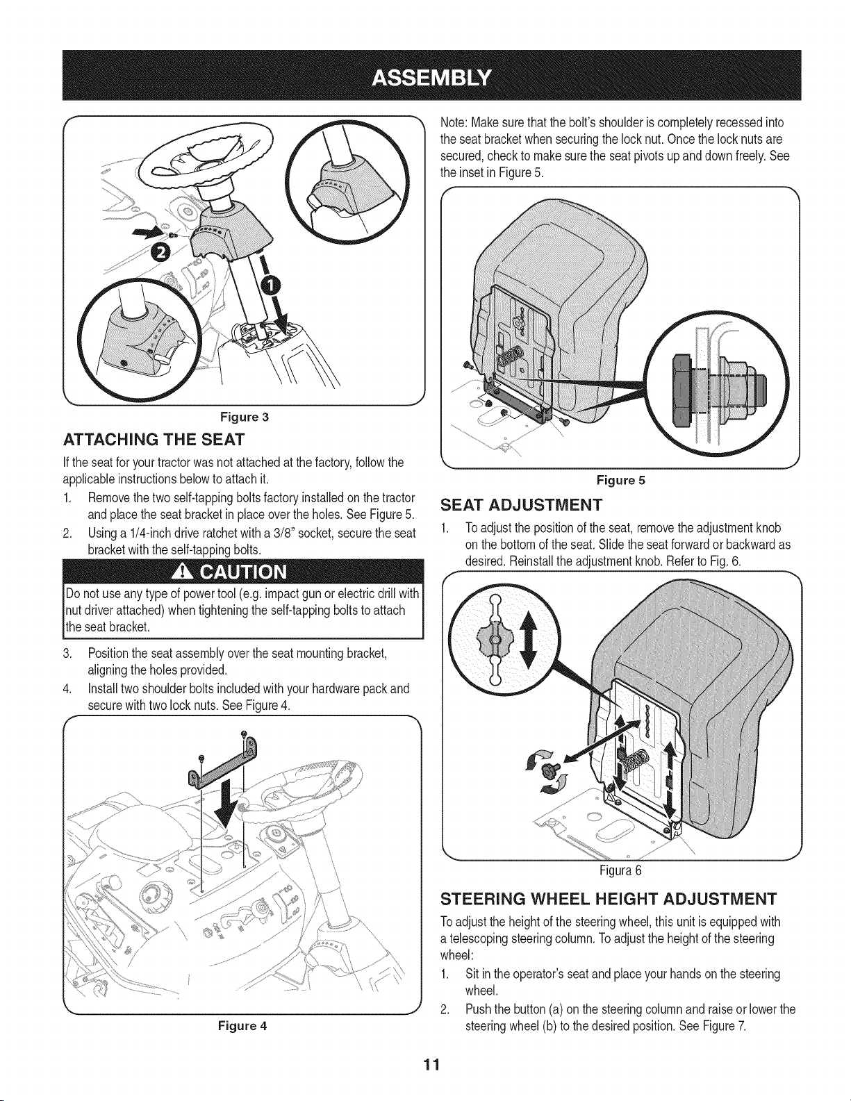
Note:Makesurethat the bolt's shoulderis completelyrecessedinto
the seat bracketwhensecuringthe locknut.Oncethe locknuts are
secured,checkto makesurethe seatpivotsup and downfreely.See
the inset in Figure5.
Figure 3
ATTACHING THE SEAT
If the seatfor yourtractorwas notattachedat thefactory,followthe
applicableinstructionsbelowto attachit.
1. Removethetwo self-tappingboltsfactoryinstalledon the tractor
andplacethe seat bracketin placeoverthe holes.SeeFigure5.
2. Usinga 1/4-inchdrive ratchetwith a 3/8" socket,securetheseat
bracketwiththe self-tappingbolts.
Do notuse anytype of powertool (e.g.impactgunor electricdrill with
nutdriverattached)when tighteningthe self-tappingboltsto attach
the seatbracket.
3. Positionthe seat assemblyoverthe seatmountingbracket,
aligningthe holesprovided.
4. Installtwoshoulderbolts includedwith yourhardwarepackand
securewithtwo lock nuts. SeeFigure4.
\\
Figure 4
Figure 5
SEAT ADJUSTMENT
1. Toadjust the positionof the seat,removethe adjustmentknob
on the bottomof the seat.Slidethe seatforwardor backwardas
desired.Reinstallthe adjustmentknob.Referto Fig.6.
\
Figura6
STEERING WHEEL HEIGHT ADJUSTMENT
Toadjustthe heightof the steeringwheel,thisunit is equippedwith
a telescopingsteeringcolumn.Toadjustthe heightof the steering
wheel:
1. Sit inthe operator'sseatandplaceyour handson the steering
wheel.
2. Pushthe button(a)on thesteeringcolumnandraiseor lowerthe
steeringwheel(b)to thedesiredposition.See Figure7.
11
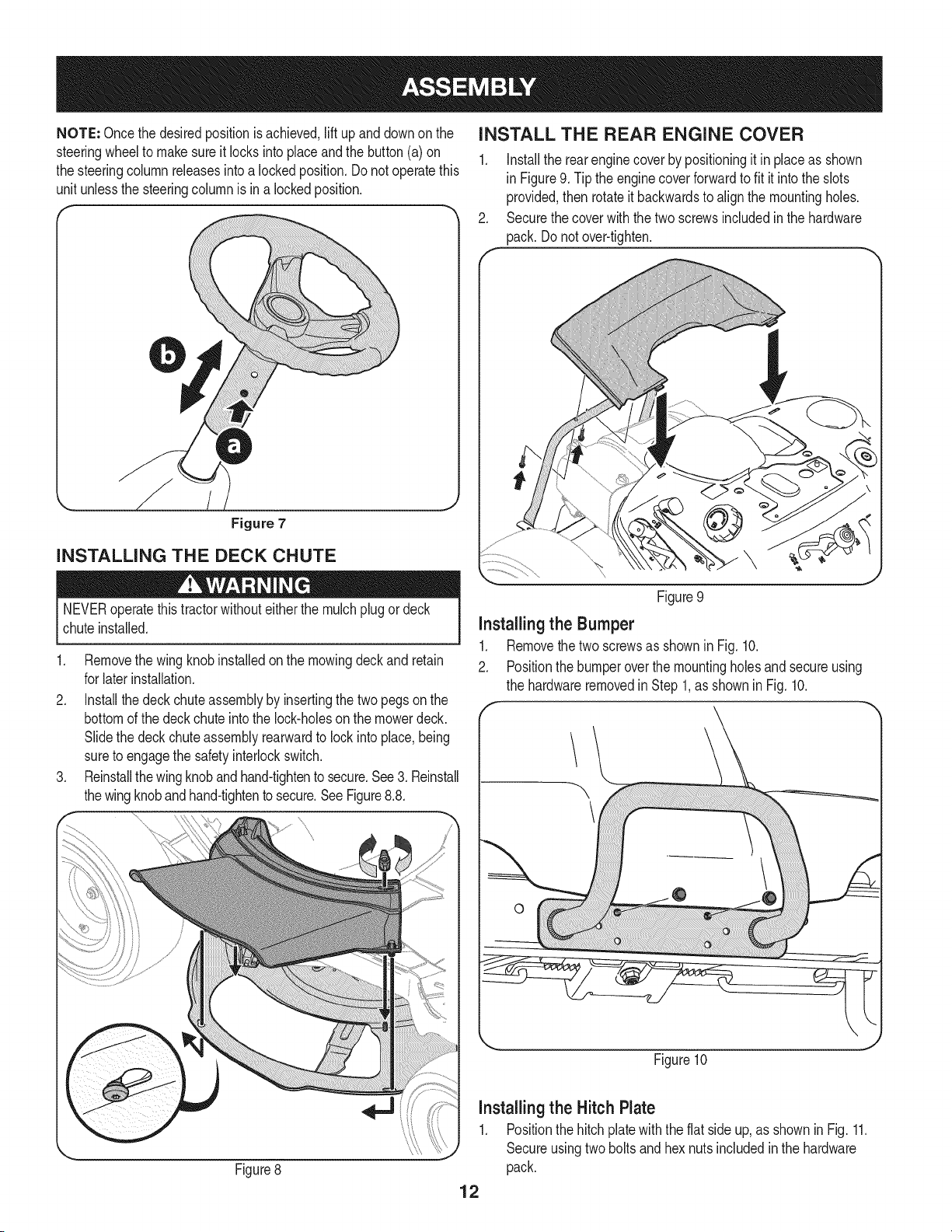
NOTE: Oncethe desiredpositionis achieved,lift upand downon the
steeringwheelto makesureit locksintoplaceandthe button (a) on
the steeringcolumnreleasesintoa lockedposition.Donot operatethis
unit unlessthe steeringcolumnis ina lockedposition.
INSTALL THE REAR ENGINE COVER
1. Installthe rearenginecoverby positioningit inplaceas shown
in Figure9. Tipthe enginecoverforwardto fit it intothe slots
provided,then rotateit backwardsto alignthe mountingholes.
2. Securethecoverwiththetwo screwsincludedin the hardware
pack. Donot over-tighten.
Figure 7
INSTALLING THE DECK CHUTE
NEVERoperatethistractorwithouteitherthe mulchplug or deck
chuteinstalled.
1. Removethe wing knobinstalledonthe mowingdeckand retain
for laterinstallation.
2. Installthedeckchuteassemblyby insertingthetwo pegsonthe
bottomof the deckchuteintothe lock-holeson the mowerdeck.
Slidethe deck chute assemblyrearwardto lock into place,being
sureto engagethe safetyinterlockswitch.
3. Reinstallthewingknoband hand-tightento secure.See3. Reinstall
thewingknobandhand-tightento secure.SeeFigure8.8.
\
Figure8
Figure9
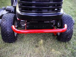
Installingthe Bumper
1. Removethe twoscrewsas shownin Fig. 10.
2. Positionthe bumperoverthe mountingholesandsecureusing
the hardwareremovedin Step1,as showninFig. 10.
Figure10
installingthe Hitch Plate
1. Positionthe hitch platewith the flat sideup, as shownin Fig. 11.
Secureusingtwo bolts and hex nutsincludedinthe hardware
pack.
12
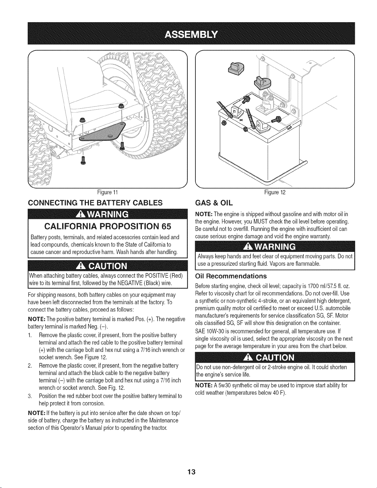
Figure11
CONNECTING THE BATTERY CABLES
CALiFORNiA PROPOSITION 65
Batteryposts,terminals,and relatedaccessoriescontainleadand
leadcompounds,chemicalsknownto the Stateof Californiato
causecancerand reproductiveharm.Washhandsafterhandling.
Whenattachingbatterycables,alwaysconnectthe POSITIVE(Red)
wireto its terminalfirst, followedby the NEGATIVE(Black)wire.
For shippingreasons,bothbatterycablesonyourequipmentmay
havebeenleft disconnectedfromtheterminalsat the factory.To
connectthe batterycables,proceedas follows:
NOTE: The positivebatteryterminalis markedPos.(+). The negative
batteryterminalis markedNeg.(-).
1. Removetheplasticcover,if present,fromthe positivebattery
terminalandattachthe redcable to the positivebatteryterminal
(+)withthe carriagebolt andhex nutusinga 7/16inchwrenchor
socketwrench.See Figure12.
2. Removetheplasticcover,if present,fromthe negativebattery
terminalandattachthe blackcableto the negativebattery
terminal(-) withthe carriageboltandhex nut usinga 7/16inch
wrenchor socketwrench.SeeFig. 12.
3. Positionthe redrubberbootoverthe positivebatteryterminalto
helpprotectit fromcorrosion.
NOTE: If the batteryis put intoserviceafterthedate shownontop/
sideof battery,chargethe batteryas instructedinthe Maintenance
sectionof thisOperator'sManualpriorto operatingthe tractor.
Figure12
GAS & OIL
NOTE: Theengineis shippedwithoutgasolineand with motoroil in
the engine.However,you MUSTchecktheoil levelbeforeoperating.
Becarefulnotto overfill.Runningthe enginewithinsufficientoil can
causeseriousenginedamageand voidthe enginewarranty.
Alwayskeephandsand feet clearof equipmentmovingparts.Do not
usea pressurizedstartingfluid.Vaporsare flammable.
Oil Recommendations
Beforestartingengine,checkoil level;capacityis 1700ml/57.5ft. oz.
Referto viscositychart for oil recommendations.Donot over-fill.Use
a syntheticor non-synthetic4-stroke,or anequivalenthighdetergent,
premiumqualitymotoroil certifiedto meetor exceedU.S.automobile
manufacturer'srequirementsfor serviceclassificationSG,SE Motor
oils classifiedSG,SF will showthisdesignationonthe container.
SAE10W-30is recommendedfor general,all temperatureuse.If
singleviscosityoil is used, selectthe appropriateviscosityon the next
pagefor theaveragetemperaturein yourareafromthe chart below.
Donot use non-detergentoil or2-strokeengineoil. Itcouldshorten
the engine'sservicelife.
NOTE: A5w30 syntheticoil may be usedto improvestartability for
cold weather(temperaturesbelow40 F).
13
mE/ml,
V
mmmmm_
m mlb
(°C)-30o -20o -I0 o 0o 100 200 300 400
(oF)-20 o 0o 15o 300 500 700 850 1050
J
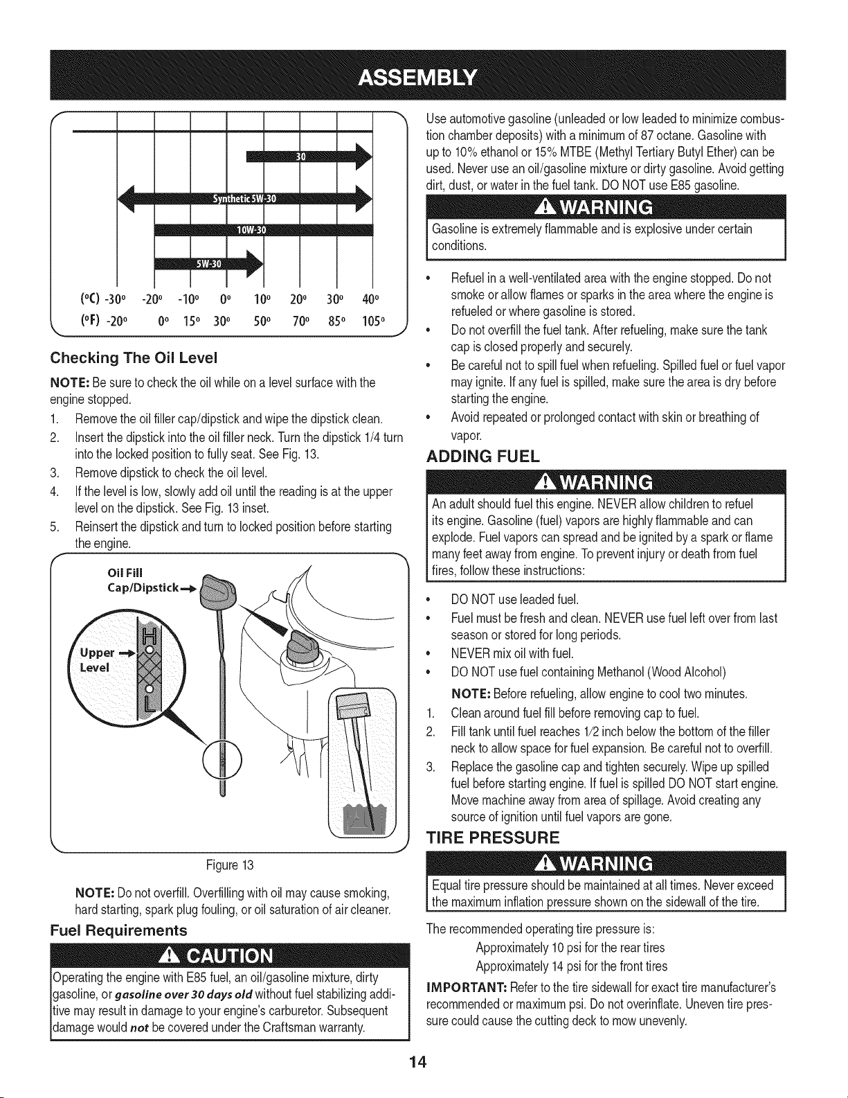
Checking The Oil Level
NOTE: Be sureto checkthe oilwhileon a levelsurfacewiththe
enginestopped.
1. Removethe oil fillercap/dipstickand wipethe dipstickclean.
2. Insertthe dipstickintothe oil fillerneck.Turnthe dipstick1/4turn
intothe lockedpositionto fullyseat.See Fig. 13.
3. Removedipstick to checktheoil level.
4. If the levelis low,slowlyaddoil untilthe readingisat the upper
levelonthe dipstick.SeeFig.13inset.
5. Reinsertthe dipstickandturnto lockedpositionbeforestarting
theengine.
Oil Fill
Cap/Dipstick--_
Level
,J
Figure13
NOTE: Donot overfill.Overfillingwithoil maycausesmoking,
hardstarting,sparkplug fouling,or oil saturationof air cleaner.
Fuel Requirements
Operatingthe enginewith E85fuel, an oil/gasolinemixture,dirty
gasoline,or gasoline over 30daysold withoutfuel stabilizingaddi-
tivemayresultin damageto yourengine'scarburetor.Subsequent
damagewouldnot becoveredunderthe Craftsmanwarranty.
Useautomotivegasoline(unleadedor lowleadedto minimizecombus-
tion chamberdeposits)with a minimumof 87 octane.Gasolinewith
up to 10%ethanolor 15%MTBE(MethylTertiaryButylEther)can be
used.Neverusean oil/gasolinemixtureordirty gasoline.Avoidgetting
dirt, dust,or waterinthe fuel tank.DO NOTuse E85 gasoline.
Gasolineis extremelyflammableand is explosiveundercertain
conditions.
,, Refuelina well-ventilatedareawith the enginestopped.Do not
smokeor allowflamesor sparksin the areawherethe engineis
refueledor wheregasolineis stored.
* Donot overfillthe fueltank.After refueling,makesurethe tank
cap is closedproperlyandsecurely.
* Becarefulnotto spillfuel whenrefueling.Spilledfuel orfuel vapor
mayignite.If any fuelis spilled,makesurethe areais dry before
startingthe engine.
* Avoidrepeatedorprolongedcontact with skinor breathingof
vapor.
ADDING FUEL
Anadultshouldfuelthis engine.NEVERallowchildrento refuel
itsengine.Gasoline(fuel)vaporsare highlyflammableandcan
explode.Fuelvaporscan spreadand be ignitedbya sparkor flame
manyfeetawayfrom engine.Topreventinjuryordeathfrom fuel
fires,followtheseinstructions:
* DONOTuseleadedfuel.
* Fuelmustbefreshandclean.NEVERusefuel leftoverfromlast
seasonor storedfor long periods.
* NEVERmix oil with fuel.
* DONOTusefuelcontainingMethanol(WoodAlcohol)
NOTE: Beforerefueling,allowenginetocool two minutes.
1. Cleanaroundfuel fill beforeremovingcap to fuel.
2. Filltankuntilfuel reaches1/2inch belowthe bottomof the filler
neckto allowspace forfuel expansion.Be careful notto overfill.
3. Replacethe gasolinecapand tightensecurely.Wipe up spilled
fuel beforestartingengine.Iffuel is spilledDO NOTstartengine.
Movemachineawayfromarea of spillage.Avoidcreatingany
sourceof ignitionuntil fuelvaporsaregone.
TIRE PRESSURE
Equaltire pressureshouldbe maintainedat all times. Neverexceed
the maximuminflationpressureshownonthe sidewallof thetire.
The recommendedoperatingtire pressureis:
Approximately10psi forthe reartires
Approximately14psifor the front tires
IMPORTANT: Referto the tire sidewallfor exacttire manufacturer's
recommendedormaximumpsi.Donot overinflate.Uneventire pres-
surecould causethe cuttingdeckto mowunevenly.
14
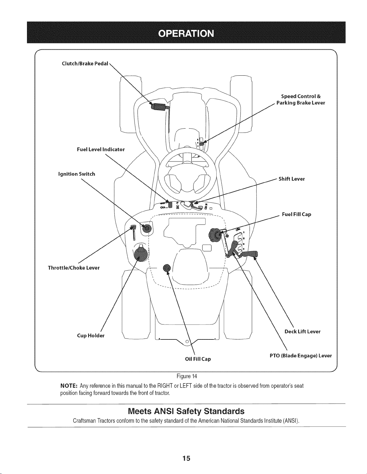
Clutch/Brake
Speed Control &
Parking Brake Lever
Fuel Level indicator
ignition Switch
Shift Lever
Throttle/Choke Lever
[]
Fuel Fill Cap
Cup Holder
Deck Lift Lever
Oil Fill Cap
PTO (Blade Engage) Lever
Figure14
NOTE: Any referencein thismanualto the RIGHTor LEFTside of thetractorisobservedfromoperator'sseat
positionfacingforwardtowardsthe front of tractor.
Meets ANSi Safety Standards
CraftsmanTractorsconformto the safetystandardof theAmericanNationalStandardsInstitute(ANSI).
15

Throttle / Choke Control
Thethrottlecontrolleveris locatedon the left fenderof the tractoras
seenfromthe operator'sposition,seeFig. 14.Thislevercontrolsthe
speedof the engine,as wellas the chokewhenit is pushedall the
wayforward.When set ina givenposition,the throttlewill maintaina
uniformenginespeed.
iMPORTANT: Whenoperatingthetractorwith the cuttingdeck
engaged,becertainthat the throttleleverisalwaysinthe FAST
(rabbit)position.
Movingthethrottleleverall thewayforwardactivatestheengine's
chokecontrol. Activatingthe chokecontrolclosesthechokeplateon
thecarburetorandaids instartingthe engine.
Referto StartingThe Engineinthe Operationsectionof this manual
for detailedstartinginstructions.
ignition Switch
The ignitionswitchislocatedon the leftfenderof thetractoras seen
fromthe operator'sposition,adjacentto the Throttle/ChokeControl.
Activatethe ignitionSwitchto startthe engineby insertingthe keyinto
the ignitionswitchand turnclockwiseto the STARTposition.Release
the key intothe ONpositiononce enginehasfired.SeeFig.15.
On
off
Start
Figure 15
Clutch=Brake Pedal
Theclutch-brakepedalis locatedonthe left sideof the lawntractor,
alongthe runningboard.Depressthe clutch-brakepedalpartway
downwhenslowingthetractorbychangingspeeds(Refer to Speed
Control Lever). Depressthepedalall thewaydownto engagethe
discbrakeandbringthe tractortoa completestop.
NOTE: The clutch-brakepedalmustbe completelydepressedto start
theengine.Referto SafetyInterlockSwitchesinthe Operationsection
of this manual.
Shift Lever
The shiftleveris locatedon the controlpaneljust belowthe seat,inthe
centerof the tractor.Ithas threepositions,FORWARD,NEUTRALand
REVERSE.The brakepedalmustbe depressedandthe tractormust
not be in motion whenmovingthe shiftlever.See Fig. 16.
iMPORTANT: Neverforcethe shift lever.Doingsomayresultin
seriousdamageto the tractor'stransmission.
f
N
Figure 16
Speed Control Lever
The speedcontrollever,locatedon the rightside of thetractor's
steeringconsole,allowsyou to regulatethegroundspeedof the lawn
tractor.
To use,depressthe clutch-brakepedalandmovethe leveroutof
the parkingbrakenotchand forwardto increasethe tractor'sground
speed.Whena desiredspeedhasbeenreached,releasethe leverinto
an appropriatenotchto maintainthatspeed.
To slowthe tractor'sground speed,depressthe clutch-brakepedaland
movethespeedcontrol leverrearwardand releaseit intoa notch.
Parking Brake
To set the parkingbrake,fullydepresstheclutch-brakepedal.Move
the speedcontrolleverallthe way downandintothe parkingbrake
position.Releasethe clutch-brakepedalto allowthe parkingbraketo
engage.
To releasethe parkingbrake,depressthe clutch-brakepedaland
movethespeedcontrol leverout of the parkingbrakepositionintothe
desiredposition.Releasethe clutch-brakepedal.
NOTE: The parkingbrakemustbeset if theoperatorleavesthe seat
withthe engine runningor theenginewill automaticallyshutoff.
Fuel Lever Indicator
The FuelLeverIndicatoris locatedbelowthe seatonthe left hand side
fromthe operator'spositioninthe controlpanel.Usethiswindowto
identifythe tractor'sfuel needs.SeeFig. 17.
16
©
Figure 17
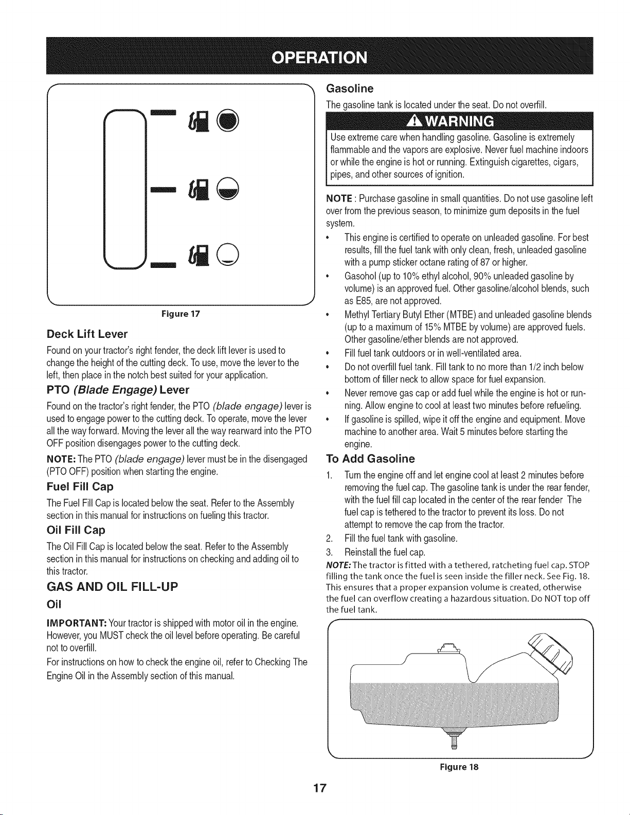
Deck Lift Lever
Foundon yourtractor'srightfender,the deck lift leverisusedto
changethe heightof the cuttingdeck.Touse, movethe leverto the
left,then placeinthe notchbest suitedfor yourapplication.
PTO (Blade Engage) Lever
Foundon the tractor'srightfender,the PTO (blade engage) leveris
usedto engagepowerto thecuttingdeck.To operate,movethe lever
allthe way forward.Movingthe leverall the way rearwardintothe PTO
OFFpositiondisengagespowerto thecuttingdeck.
NOTE: The PTO (blade engage) levermust be inthe disengaged
(PTOOFF) positionwhen startingthe engine.
Fuel Fill Cap
The FuelFillCap islocatedbelowthe seat.Referto the Assembly
sectioninthismanualfor instructionsonfuelingthis tractor.
Oil Fill Cap
TheOil Fill Capislocatedbelowthe seat.Referto the Assembly
sectioninthismanualfor instructionsoncheckingandaddingoil to
thistractor.
GAS AND OIL FILL-UP
Oil
IMPORTANT: Yourtractorisshippedwith motoroil in the engine.
However,you MUSTcheckthe oil levelbeforeoperating.Becareful
not tooverfill.
For instructionsonhowto checkthe engineoil, referto CheckingThe
EngineOilin the Assemblysectionof thismanual.
Gasoline
The gasolinetank islocatedunderthe seat. Donot overfill.
Useextremecarewhenhandlinggasoline.Gasolineisextremely
flammableandthe vaporsare explosive.Neverfuel machineindoors
orwhilethe engineis hotor running.Extinguishcigarettes,cigars,
pipes,andothersourcesof ignition.
NOTE : Purchasegasolineinsmallquantities.Donot usegasolineleft
overfrom the previousseason,to minimizegumdepositsinthe fuel
system.
• Thisengineis certifiedto operateon unleadedgasoline.Forbest
results,fill the fuel tankwith onlyclean,fresh,unleadedgasoline
witha pumpstickeroctaneratingof 87 or higher.
• Gasohol(up to 10%ethylalcohol,90%unleadedgasolineby
volume)isan approvedfuel. Othergasoline/alcoholblends,such
as E85,are notapproved.
MethylTertiaryButylEther(MTBE)and unleadedgasolineblends
(upto a maximumof 15%MTBEbyvolume)are approvedfuels.
Othergasoline/etherblendsare not approved.
• Fillfuel tank outdoorsor inwell-ventilatedarea.
• Donot overfillfueltank. Fill tankto nomorethan 1/2 inchbelow
bottomof filler neckto allowspaceforfuel expansion.
• Neverremovegascap or addfuelwhilethe engineis hotor run-
ning.Allowengineto coolat leasttwominutesbeforerefueling.
• If gasolineis spilled,wipeitoff the engineandequipment.Move
machineto anotherarea.Wait 5 minutesbeforestartingthe
engine.
Add GasolineTo
1.
Turntheengine off and letenginecool at least2 minutesbefore
removingthe fuel cap. Thegasolinetankis underthe rearfender,
withthe fuel fill cap locatedinthe centerof the rear fender The
fuel cap is tetheredto the tractorto preventitsloss. Donot
attemptto removethecap from the tractor.
2. Fillthe fueltankwith gasoline.
3. Reinstallthe fuel cap.
NOTE: The tractor is fitted with a tethered, ratcheting fuel cap. STOP
filling the tank once the fuel is seen inside the filler neck. See Fig. 18.
This ensures that a proper expansion volume is created, otherwise
the fuel can overflow creating a hazardous situation. Do NOTtop off
the fuel tank.
17
Figure 18
Safety interlock Switches
The safetyinterlocksystemisdesignedfor safeoperationof thetrac-
tor.Ifthis systemshouldevermalfunction,do notoperatethetractor.
Immediatelycontact1-800i4iMY-HOMEto havethe systemserviced.
• The safetyinterlocksystempreventstheenginefromstarting
unlessthe parkingbrakeis engagedandthe PTO(BladeEngage)
leveris inthe disengaged(OFF)position.
• The safetyinterlocksystemwill automaticallyshut off theengineif
theoperatorleavesthe seatbeforeengagingthe parkingbrake.
• The safetyinterlocksystemwill automaticallyshut off theengine
ifthe operatorleavesthetractor'sseatwith the PTO(Blade
Engage)leverengaged,regardlessof whetherthe parkingbrake
is engaged.
• Theenginewill automaticallyshutoffif the PTO(BladeEngage)
leveris movedintothe engaged(ON)positionwiththe shift lever
in Reverse.
Donot operatethe tractorif the interlocksystemis malfunctioning.
Thissystemwasdesignedfor yoursafetyand protection.
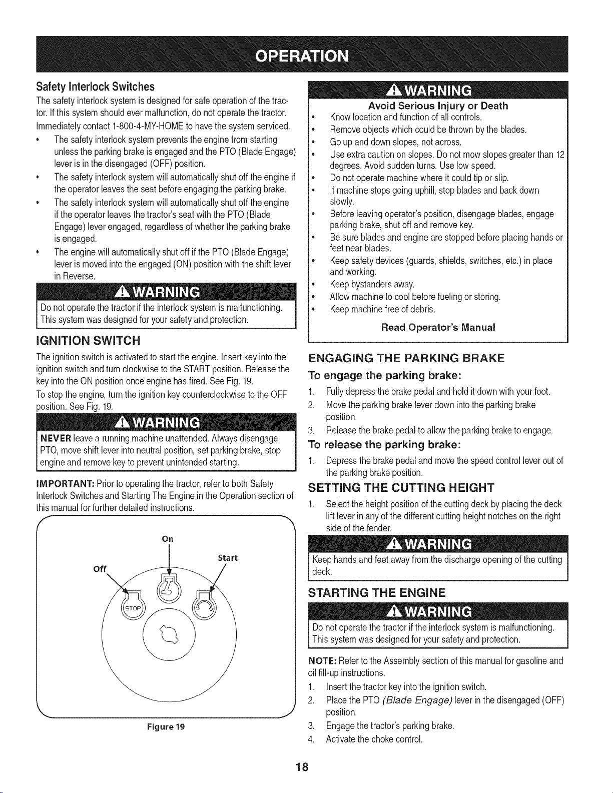
iGNiTiON SWITCH
The ignitionswitchis activatedto startthe engine.Insertkeyinto the
ignitionswitchandturnclockwiseto the STARTposition.Releasethe
keyintothe ON positiononceenginehasfired.See Fig. 19.
Tostoptheengine,turnthe ignitionkeycounterclockwiseto the OFF
position.SeeFig. 19.
NEVER leavea runningmachineunattended.Alwaysdisengage
PTO,moveshift leverintoneutralposition,setparkingbrake,stop
leng ne andremovekeyto preventunntendedstartng.
IMPORTANT: Priorto operatingthetractor,referto both Safety
InterlockSwitchesandStartingThe Enginein the Operationsectionof
thismanualfor furtherdetailedinstructions.
On
Start
off
Figure 19
J
Avoid Serious Injury or Death
• Knowlocationand functionof all controls.
• Removeobjectswhichcouldbe thrownbythe blades.
• Goup anddownslopes,not across.
• Useextra cautionon slopes.Do notmow slopesgreaterthan 12
degrees.Avoidsuddenturns.Use lowspeed.
• Donotoperatemachinewhereitcould tip orslip.
• If machinestopsgoing uphill,stopbladesand backdown
slowly.
• Beforeleavingoperator'sposition,disengageblades,engage
parkingbrake,shutoff andremovekey.
• Be surebladesandengine are stoppedbeforeplacinghandsor
feetnear blades.
• Keepsafetydevices(guards,shields,switches,etc.) in place
andworking.
• Keepbystandersaway.
• Allowmachineto coolbeforefuelingor storing.
• Keepmachinefreeof debris.
Read Operator's Manual
ENGAGING THE PARKING BRAKE
To engage the parking brake:
1. Fullydepressthebrakepedalandhold it downwith yourfoot.
2. Movetheparkingbrakeleverdown intothe parkingbrake
position.
3. Releasethe brakepedalto allowthe parkingbraketo engage.
To release the parking brake:
1. Depressthe brakepedaland movethe speedcontrolleverout of
the parkingbrakeposition.
SETTING THE CUTTING HEIGHT
1. Selectthe heightpositionof the cuttingdeckby placingthe deck
lift leverin anyof the differentcuttingheightnotchesonthe right
side of the fender.
Keephandsandfeetawayfromthedischargeopeningof the cutting
deck.
STARTING THE ENGINE
Do notoperatethe tractorif the interlocksystemis malfunctioning.
Thissystemwasdesignedfor your safetyandprotection.
NOTE: Referto the Assemblysectionof this manualfor gasolineand
oil fill-upinstructions.
1. Insertthe tractorkeyintothe ignitionswitch.
2. Placethe PTO (Blade Engage) leverinthe disengaged(OFF)
position.
3. Engagethe tractor'sparkingbrake.
4. Activatethe chokecontrol.
18
5. Turnthe ignitionkeyclockwiseto the STARTposition.Afterthe
enginestarts,releasethe key.Itwill returnto the ON position.
IMPORTANT:DoNOT holdthe keyin the STARTpositionfor longer
thanten secondsat a time. Doingso maycausedamageto your
engine'selectricstarter.
6. After theenginestarts,deactivatethe chokecontrol byplacingthe
throttlecontrolintothe FASTposition.
NOTE: Do NOTleavethe chokecontrolon whileoperatingthetractor.
Doingso will resultin a "rich" fuelmixtureandcausethe engineto run
poorly.
STOPPING THE ENGINE
Ifyou strikea foreignobject, stopthe engine,disconnectthespark
plugwire(s) andgroundagainsttheengine.Thoroughlyinspectthe
machineforany damage.Repairthe damagebeforerestartingand
operating.
If the bladesare engaged,placethe PTO (Blade Engage)
leverin the disengaged(OFF)position.
2. Turnthe ignitionkeycounterclockwiseto the STOPposition.
3. Removethekeyfrom the ignitionswitchto preventunintended
starting.
DRIVING THE TRACTOR
Avoidsuddenstarts,excessivespeedandsuddenstops.
Do notleavethe seatof thetractorwithoutfirst placingthe PTO
(BladeEngage)leverin the disengaged(OFF)position,depressing
the brakepedal and engagingthe parkingbrake.Ifleavingthetractor
unattended,alsoturn the ignitionkey off and removethe key.
Alwayslookdownand behind beforeand whilebackingupto avoida
back-overaccident.
1. Depressthe brakepedalandmovethe speedcontrolleverout of
the parkingbrakeposition,thenlet the pedal release.
2. Movethe throttleleverintothe FAST(rabbit) position.
3. Placethe shiftleverin eitherthe FORWARDor REVERSE
position.
IMPORTANT: DoNOT usethe shift leverto changethe direction
of travelwhenthe tractorisinmotion.Alwaysuse thebrakepedalto
bringthetractorto a completestopbeforeshifting.
4. Releasethe parkingbrakebydepressingthe clutch-brakepedal
andpositioningthe speedcontrolleverindesiredposition.
IMPORTANT= First-timeoperatorsshouldusespeedpositions1or
2. Becomecompletelyfamiliarwiththe tractor'soperationand controls
beforeoperatingthe tractorinhigherspeedpositions.
5. Releaseclutch-brakepedalslowlyto put unit intomotion.
6. The lawntractorisbroughtto a stop by depressingtheclutch-
brakepedal.
NOTE=Whenoperatingthe unit initially,therewill belittledifference
betweenthe highesttwospeedsuntilafter the beltshaveseated
themselvesintothe pulleysduring the break-inperiod.
Beforeleavingthe operator'spositionfor any reason,disengagethe
blades,placethe shift leverin neutral,engagethe parkingbrake,
shutengineoff and removethe key.
IMPORTANT: Whenstoppingthe tractorforany reasonwhileon a
grasssurface,always:
1. Placethe shift leverinneutral,
2. Engagethe parkingbrake,
3. Shutengineoffand removethe key.Doingso will minimizethe
possibilityof havingyour lawn"browned"by hot exhaustfrom
yourtractor'srunningengine.
Ifunit stallswithspeedcontrolinhigh speed,or if unitwill not operate
with speedcontrolleverin a low speedposition,proceedasfollows:
1. Placeshift leverin NEUTRAL.
2. Restartengine.
3. Placespeedcontrolleverin highestspeedposition.
4. Releaseclutch-brakepedalfully.
5. Depressclutch-brakepedal.
6. Placespeedcontrolleverin desiredposition.
7. Placeshift leverin either FORWARDor REVERSE,and follow
normaloperatingprocedures.
DRIVING ON SLOPES
Referto the SLOPEGAUGEinthe SafetyInstructionssectionof the
manualto helpdetermineslopeswhereyou mayoperatethis tractor
safely.
Donot mowon inclineswitha slopeinexcessof 12degrees(a rise
of approximately2 feetevery 10feet).The tractorcouldoverturnand
causeseriousinjury.
• Mowup and down slopes,NEVERacross.
• Exerciseextremecautionwhenchangingdirectionon slopes.
• Watchfor holes,ruts,bumps,rocks,or otherhiddenobjects.
Uneventerraincouldoverturnthe machine.Tallgrasscan hide
obstacles.
• Avoidturnswhendrivingon a slope.If a turnmustbe made,turn
downthe slope.Turningupa slopegreatlyincreasesthe chance
of a roll over.
• Avoidstoppingwhen drivingup a slope.If itis necessaryto stop
whiledrivingup a slope,start upsmoothlyandcarefullyto reduce
the possibilityof flippingthe tractoroverbackward.
19
ENGAGING THE BLADES
Engagingthe PTO(Blade Engage)transferspowerto thecuttingdeck.
Toengagethe blades,proceedas follows:
1. Movethe throttle/chokecontrolleverto the FAST(rabbit)position.
2. Graspthe PTO(BladeEngage)leverand pivotit all the way
forwardintothe engaged(ON)position.
3. Keepthe throttleleverin the FAST(rabbit)positionfor the most
efficientuseof the cuttingdeck.
NOTE: The enginewill automaticallyshutoff if the PTO(Blade
Engage)leveris movedintothe engaged(ON) positionwiththe shift
leverin Reverse.
MULCHING
A mulchkit is availableas an attachment.Mulchingis a processof
recirculatinggrassclippingsrepeatedlybeneaththe cuttingdeck. The
ultra-fineclippingsarethenforced back intothe lawnwheretheyact
as a naturalfertilizer.Contactthe nearest Parts & Repair Service
Centerto purchasea mulchkit forthis unit.
Tolocatethe nearestParts& RepairServiceCenter,contact
1-800-4-MY-HOME®.
USING THE DECK LIFT LEVER
To raisethe cuttingdeck,movethe decklift leverto the left,then place
it in the notchbestsuitedfor yourapplication.Referto SettingThe
CuttingHeightearlierinthis section.
MOWING
To helpavoidbladecontactor a thrownobject injury,keepbystand-
ers,helpers,childrenand petsat least 75 feetfromthe machine
whileit is in operation.Stopmachineif anyoneentersthe area.
The followinginformationwill behelpfulwhenusingthe cuttingdeck
withyourtractor:
Planyourmowingpatternto avoiddischargeof materialstoward
roads,sidewalks,bystandersand the like.Also,avoiddischarging
materialagainstawall orobstructionwhichmay causedischarged
materialto ricochetbacktowardthe operator.
• Donot mowat highground speed,especiallyif a mulchkit or
grasscollectoris installed.
• Forbestresultsit is recommendedthat the first two laps becut
withthe dischargethrowntowardsthe center.After the firsttwo
laps, reversethedirectionto throwthe dischargeto theoutside
for the balanceof cutting.This will givea betterappearanceto the
lawn.
• Donot cut the grasstooshort. Shortgrassinvitesweedgrowth
andyellowsquicklyin dry weather.
• Mowingshouldalwaysbe done with the engineat full throttle.
• Underheavierconditionsit maybe necessaryto go backoverthe
cut areaa secondtimeto get a cleancut.
• Do NOTattemptto mowheavybrushand weedsand extremely
tall grass.Yourtractoris designedto mowlawns,NOTclear
brush.
• Keepthe bladesharpand replacethe bladewhenworn.Refer
to CuttingBladein the Maintenancesectionof this manualfor
properbladesharpeninginstructions.
• The lampsturn OFFwhenthe ignitionkey is movedto the STOP
position.
2O
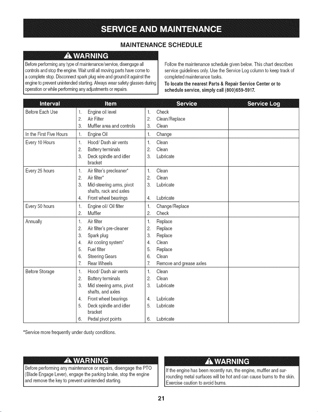
MAINTENANCE SCHEDULE
Beforeperforminganytypeof maintenance/service,disengageall
controlsandstoptheengine.Waituntilall movingpartshavecometo
acompletestop.Disconnectsparkplugwireandgrounditagainstthe
engineto preventunintendedstarting.Alwayswearsafetyglassesduring
operationorwhileperforminganyadjustmentsor repairs.
Followthe maintenanceschedulegivenbelow.Thischartdescribes
serviceguidelinesonly.Usethe ServiceLogcolumnto keeptrackof
completedmaintenancetasks.
To locate the nearest Parts& Repair Service Centeror to
scheduleservice,simplycall(800)659-5917.
BeforeEachUse
In the FirstFive Hours
Every10Hours
Every25 hours
Every50 hours
Annually
BeforeStorage
1. Engineoil level
2. Air Filter
3. Mufflerareaand controls
1. EngineOil
1. Hood/Dash air vents
2. Batteryterminals
3. Deckspindleandidler
bracket
1. Air filter'sprecleaner*
2. Air filter*
3. Mid-steeringarms, pivot
shafts,rackandaxles
4. Frontwheelbearings
1. Engineoil/Oil filter
2. Muffler
1. Air filter
2. Air filter'spre-cleaner
3. Sparkplug
4. Air coolingsystem*
5. Fuelfilter
6. SteeringGears
7. RearWheels
1. Hood/Dash air vents
2. Batteryterminals
3. Midsteeringarms,pivot
shafts,andaxles
4. Frontwheelbearings
5. Deckspindleandidler
bracket
6. Pedalpivotpoints
1. Check
2. Clean/Replace
3. Clean
1. Change
1. Clean
2. Clean
3. Lubricate
1. Clean
2. Clean
3. Lubricate
4. Lubricate
1. Change/Replace
2. Check
1. Replace
2. Replace
3. Replace
4. Clean
5. Replace
6. Clean
7. Removeand greaseaxles
1. Clean
2. Clean
3. Lubricate
4. Lubricate
5. Lubricate
6. Lubricate
*Servicemorefrequentlyunderdustyconditions.
Beforeperformingany maintenanceor repairs,disengagethe PTO
(BladeEngageLever),engagethe parkingbrake,stopthe engine
andremovethe keyto preventunintendedstarting.
If the enginehas beenrecentlyrun,the engine,mufflerand sur-
roundingmetalsurfaceswill be hot andcancauseburnsto the skin.
Exercisecautionto avoidburns.
21
ENGINE MAINTENANCE
Shutoffthe enginebeforeperforminganymaintenance.To prevent
accidentalstart-up,disconnectthe sparkplug boot.
iMPORTANT: if enginemustbe tippedto transportequipmentorto
inspector removegrass, keepsparkplugsideof engineup.Transport-
ingor tippingenginesparkplug downmaycausesmoking,hard
starting,sparkplugfouling,or oil saturationof aircleaner.
Periodicinspectionandadjustmentof the engine isessentialifhigh
levelperformanceisto be maintained.Regularmaintenancewill also
ensurea longservicelife.The requiredserviceintervalsand the kind
of maintenanceto beperformedaredescribedinthe tableon the
previouspage.Followthe hourlyor calendarintervals,whicheveroccur
first.Morefrequentserviceis requiredwhenoperatinginadverse
conditions.
Ifthe enginehasbeenrunning,the mufflerwill be very hot. Be careful
notto touchthe muffler.
Servicing the Engine Oil
• Checkthe oil levelregularly.
• Besurecorrectoil levelismaintained.Checktheoil everyfiveto
ten hoursof operation,beforestartingthe engine.SeeChecking
Oil Levelinthe Assemblysection.
Onlyuse highqualitydetergentoil ratedwith APIserviceclassification
SF,SG,SH,or SJ.Selectthe oil's SAEviscositygradeaccordingto
theexpectedoperatingtemperature.Referto Gas & Oilinthe As-
semblysectionof thismanual.
Oil Drain
8. Removethe oil drainsleevefromthe oil sump.Returnthe dipstick
to the oilfilltubeand screwtheoilfill cap backintoplace.
9. Refillthe enginewiththe newmotoroil. Referto Gas& Oil inthe
Assemblysectionof this manualforinformationregardingthe
approvedoiltype.
iMPORTANT: Usedmotoroil may causeskin cancerif repeatedly
left incontactwiththe skinfor prolongedperiods.Althoughthis is
unlikelyunlessyou handleusedoil ona dailybasis,it isstill advis-
ableto thoroughlywashyourhandswithsoapand wateras soonas
possibleafterhandlingusedoil.
NOTE: Pleasedisposeof used motoroilin a mannerthat iscompat-
iblewiththeenvironment.We suggestyoutakeit in a sealedcontainer
to your localservicestationfor reclamation.Do notthrowitin the
trash,pourit downa drainoron the ground.
iMPORTANT: Besureto checkengineon a levelsurfacewiththe
enginestopped.Drainthe oilwhilethe engineis stillwarmto assure
rapidandcompletedraining.
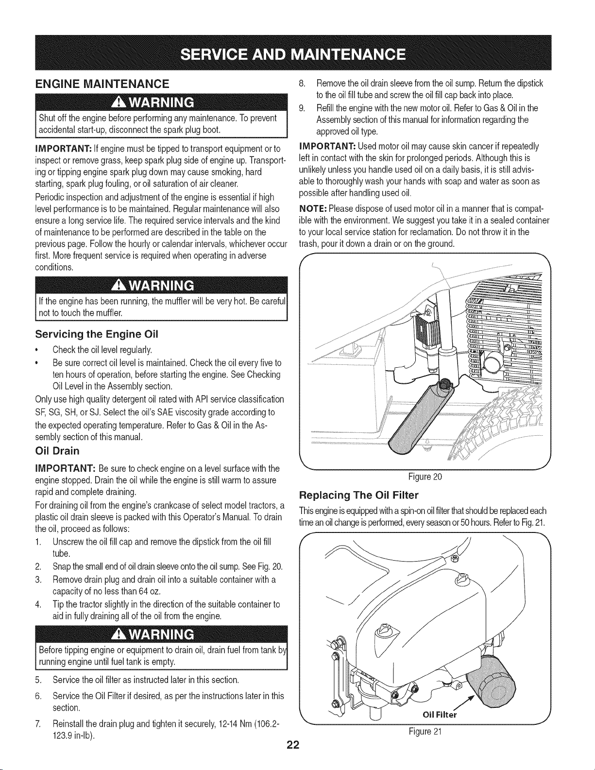
Fordrainingoilfromthe engine'scrankcaseof selectmodeltractors,a
plasticoil drainsleeveispackedwith this Operator'sManual.Todrain
theoil, proceedas follows:
1. Unscrewthe oil fill cap and removethe dipstickfromthe oil fill
tube.
2. Snapthe smallendof oildrainsleeveontothe oilsump.SeeFig.20.
3. Removedrain plug and drain oil intoa suitablecontainerwitha
capacityof no lessthan 64oz.
4. Tipthe tractorslightlyinthe directionof the suitablecontainerto
aidinfully drainingall of the oil from the engine.
Beforetippingengineor equipmentto drainoil, drain fuelfrom tank
runningengineuntilfuel tankisempty.
5. Servicethe oilfilter as instructedlater inthissection.
6. Servicethe Oil Filterifdesired,as perthe instructionslaterinthis
section.
7. Reinstallthe drainplugand tightenit securely,12-14Nm(106.2-
123.9in-lb).
Figure20
Replacing The Oil Filter
Thisengineisequippedwitha spin-onoilfilterthatshouldbe replacedeach
timeanoilchangeisperformed,everyseasonor50hours.RefertoFig.21.
_ 1/
22
OilFilter
Figure21
ToreplacetheOilFilter:
1. Draintheoilasinstructionpreviouslyinthis section.
2. Removetheoil filter. Disposeof the oldoil filter properly.
3. Lube gasketof newoil filterwithcleanoil.
4. Installandturnoil filterbyhanduntilthegasketcomesincontactwith
the sealingsurfaceof thecrankcasecover,thentightenthe oil
filter,10-12Nm(88.5-106.2in-lb),1/2-3/4turn.
5. Add oil as previouslyinstructed.
6. Makesuredipstickisinstalled.
7. Start and run engine. Checkfor leaks.
8. Stopengine. Waita few minutesand checkthe oil level. See
CheckingTheOil Levelin the Assemblysectionof this manual.
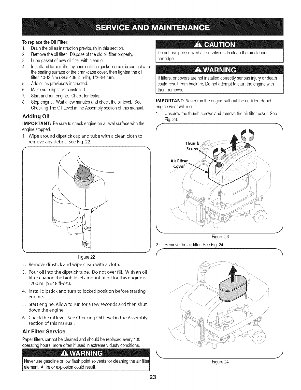
Adding Oil
iMPORTANT: Besureto checkengineon alevelsurfacewiththe
enginestopped.
1. Wipe around dipstick cap and tube with a clean cloth to
remove any debris. SeeFig. 22.
Donot use _ressurizedair or solventstoclean theair cleaner
cartridge.
Iffilters,or coversare notinstalledcorrectlyseriousinjuryordeath
could resultfrom backfire.Do not attemptto startthe enginewith
themremoved.
IMPORTANT: Neverrunthe enginewithoutthe air filter.Rapid
enginewearwill result.
1. Unscrewthethumb screwsand removethe air filter cover.See
Fig.23.
Thumb
Screw
Air Filter
, '///
/
Figure 22
2. Remove dipstick and wipe clean with a cloth.
3. Pour oil into the dipstick tube. Do not over fill. With an oil
filter change the high level amount of oil for this engine is
1700 ml (57.48 fl-oz.).
4. Install dipstick and turn to locked position before starting
engine.
5. Start engine. Allow to run for a few seconds and then shut
down the engine.
6. Check the oil level. See Checking Oil Level in the Assembly
section of this manual.
Air Filter Service
Paperfilterscannotbecleanedand shouldbe replacedevery100
operatinghours;moreoftenif usedin extremelydusty conditions.
Figure23
Removethe air filter.SeeFig. 24.
/
{ '_, ..................................../
/
/ i
Neverusegasolineor lowflash point solventsfor cleaningthe airfilter
element.Afire or explosioncould result.
23
Figure24
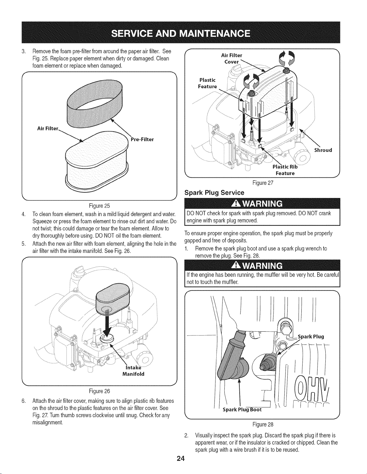
.
Removethe foam pre-filterfrom aroundthe paperair filter. See
Fig.25. Replacepaperelementwhendirty or damaged.Clean
foamelementor replacewhendamaged.
Air Filter.
Figure25
4. Tocleanfoamelement,washin a mildliquid detergentandwater.
Squeezeor pressthe foam elementto rinseoutdirt andwater.Do
nottwist; thiscoulddamageortear thefoamelement.Allowto
dry thoroughlybeforeusing.DO NOToil the foamelement.
5. Attachthe newair filter with foamelement,aligningthe holein the
airfilterwiththe intakemanifold.SeeFig.26.
Air Filter
Plastic
Feature
Shroud
)
Feature
Figure27
Spark Plug Service
DONOTcheckfor sparkwith sparkplugremoved.DONOT crank
enginewithspark plug removed.
Toensureproperengineoperation,the spark plug mustbeproperly
gappedandfree of deposits.
1. Removethe sparkplugboot and usea sparkplugwrenchto
removethe plug.See Fig. 28.
.
Figure26
Attachtheair filter cover,makingsureto align plasticrib features
onthe shroudto the plasticfeatureson the air filtercover.See
Fig.27.Turnthumbscrewsclockwiseuntil snug.Checkfor any
misalignment.
Ifthe enginehas beenrunning,the mufflerwill beveryhot.Becareful
not to touchthe muffler.
R.
24
.
SparkPlug
Figure28
Visuallyinspectthe sparkplug. Discardthe sparkplugif thereis
apparentwear,or if the insulatoris crackedor chipped.Cleanthe
sparkplugwith a wirebrushif it is to be reused.
.
f
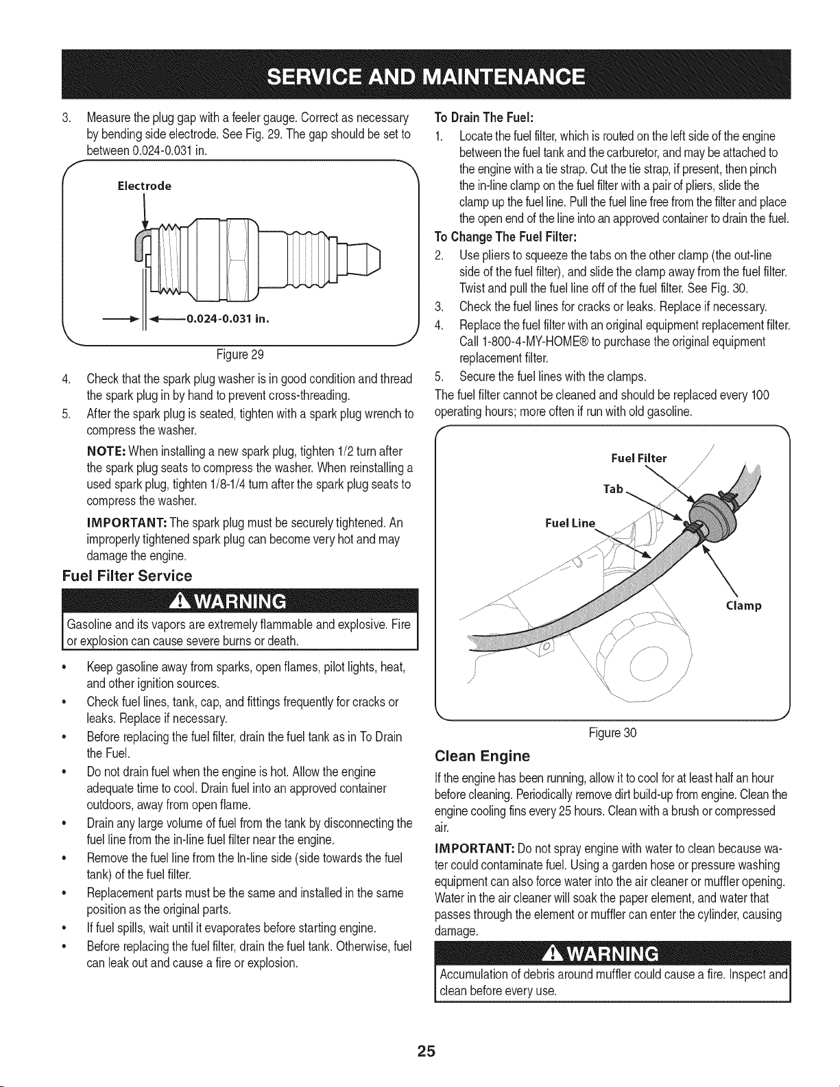
Measurethe pluggapwitha feelergauge.Correctas necessary
by bendingsideelectrode.SeeFig. 29.The gapshouldbe set to
between0.024-0.031in.
Electrode
4.
5.
Figure29
Checkthatthe sparkplugwasheris ingood conditionandthread
the sparkplug in by handto preventcross-threading.
Afterthesparkplug is seated,tightenwitha sparkplugwrenchto
compressthe washer.
NOTE: Wheninstallinga newsparkplug,tighten 1/2turn after
the sparkplug seatsto compressthe washer.Whenreinstallinga
usedsparkplug,tighten1/8-1/4turnafterthe sparkplugseatsto
compressthe washer.
IMPORTANT: The sparkplugmustbe securelytightened.An
improperlytightenedsparkplugcan becomevery hotand may
damagethe engine.
Fuel Filter Service
Gasolineandits vaporsare extremelyflammableandexplosive.Fire
or explosioncan causesevereburnsor death.
• Keepgasolineawayfrom sparks,openflames,pilotlights,heat,
andotherignitionsources.
• Checkfuellines,tank,cap,and fittingsfrequentlyfor cracksor
leaks.Replaceif necessary.
• Beforereplacingthe fuel filter,drainthe fueltank as inToDrain
the Fuel.
• Do notdrainfuel whentheengineishot. Allowtheengine
adequatetimeto cool. Drainfuel intoan approvedcontainer
outdoors,awayfromopenflame.
• Drainany largevolumeof fuelfromthe tankby disconnectingthe
fuellinefromthe in-linefuel filter near theengine.
• Removethefuel linefromthe In-lineside (sidetowardsthe fuel
tank)of thefuel filter.
• Replacementpartsmustbe the sameandinstalledin the same
positionas the originalparts.
• If fuelspills,waituntil itevaporatesbeforestartingengine.
• Beforereplacingthe fuel filter,drainthe fueltank. Otherwise,fuel
can leakoutand causea fireor explosion.
To DrainThe Fuel:
1. Locatethe fuelfilter,whichisroutedontheleftsideof theengine
betweenthefuel tankand thecarburetor,and may be attachedto
the enginewitha tie strap.Cutthe tie strap,ifpresent,thenpinch
the in-lineclamponthe fuelfilterwitha pairofpliers,slidethe
clampupthe fuelline.Pullthefuel linefreefromthe filterandplace
the openend ofthe lineintoan approvedcontainerto drainthe fuel.
To ChangeThe FuelFilter:
2. Usepliersto squeezethetabson the otherclamp(the out-line
sideof the fuelfilter),and slidetheclamp awayfrom thefuel filter.
Twistandpull the fuel line off of the fuel filter.See Fig. 30.
3. Checkthe fuel linesforcracksorleaks.Replaceifnecessary.
4. Replacethefuel filterwithanoriginalequipmentreplacementfilter.
Call1-800-4-MY-HOME®to purchasethe originalequipment
replacementfilter.
Securethe fuellineswiththe clamps.
.
The fuelfiltercannot be cleanedand shouldbe replacedevery100
operatinghours;moreoftenif runwith old gasoline.
FuelFilter /
Tab
Fuel Line
\
\
Figure30
Clean Engine
Iftheenginehasbeenrunning,allowit tocool forat leasthalfan hour
beforecleaning.Periodicallyremovedirtbuild-upfromengine.Cleanthe
enginecoolingfinsevery25hours.Cleanwitha brushor compressed
air.
IMPORTANT: Do notsprayenginewith waterto cleanbecausewa-
ter couldcontaminatefuel. Usinga gardenhoseor pressurewashing
equipmentcan alsoforce waterinto theair cleaneror muffleropening.
Waterin the air cleanerwill soakthe paperelement,and waterthat
passesthroughthe elementor mufflercanenterthe cylinder,causing
damage.
Accumulationof debrisaroundmufflercouldcausea fire.Inspectand
cleanbeforeeveryuse.
25
CUTTING DECK REMOVAL
To remove the cutting deck, proceed as follows:
1. Placethe PTO(BladeEngage)leverin the disengaged(OFF)
positionand engagetheparkingbrake.
2. Lowerthe deck by movingthe deck lift lever intothe bottom
notchon the rightfender.
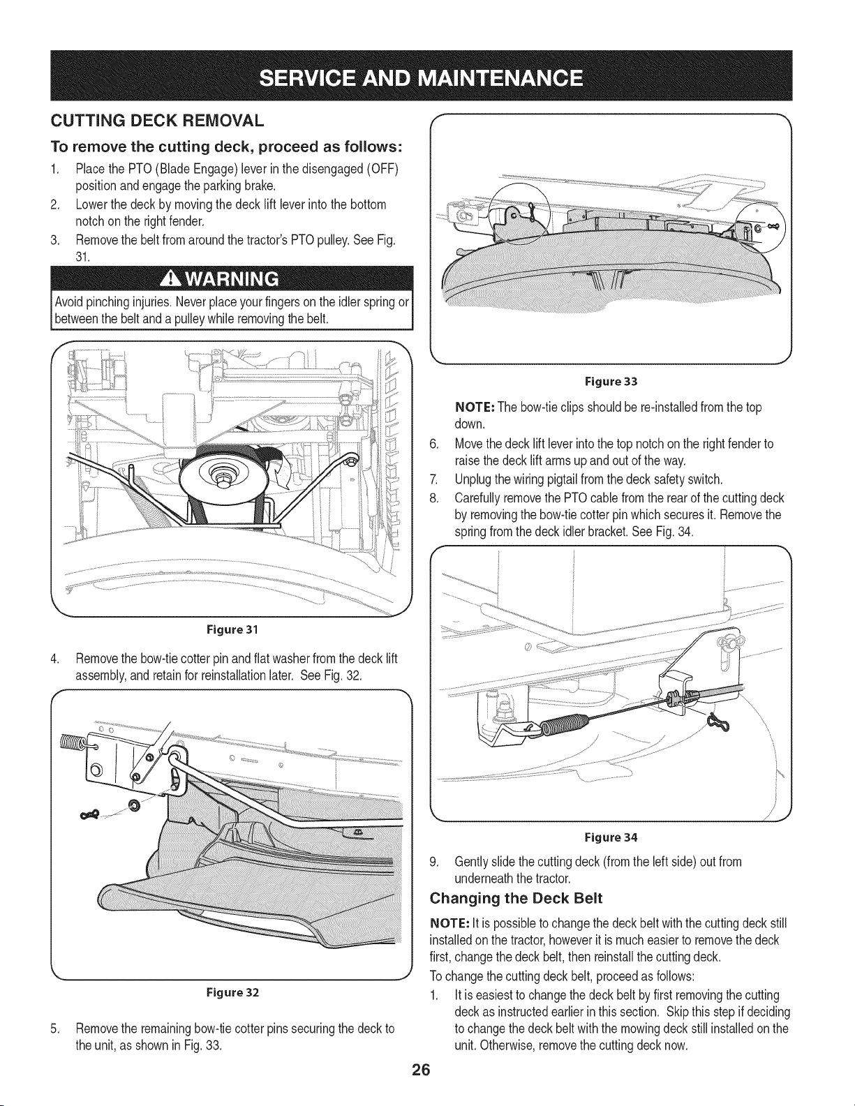
3. Removethe beltfromaroundthe tractor'sPTOpulley.SeeFig.
31.
Avoidpinchinginjuries.Neverplaceyour fingersonthe idlerspringor
betweenthe belt and a pulleywhile removingthe belt.
Figure 31
4. Removethe bow-tiecotterpin andflat washerfromthe decklift
assembly,andretainfor reinstallationlater. SeeFig.32.
,._ j
Figure 32
5. Removethe remainingbow-tiecotterpinssecuringthe deckto
the unit,as shownin Fig.33.
k,__ j
Figure 33
.
7.
8.
F
NOTE: Thebow-tieclipsshouldbe re-installedfromthe top
down.
Movethedecklift leverintothe top notchon the rightfenderto
raisethedeck lift arms up and out of the way.
Unplugthewiring pigtailfromthe decksafetyswitch.
Carefullyremovethe PTOcablefromthe rearof the cuttingdeck
by removingthe bow-tiecotterpin which securesit. Removethe
springfrom the deckidler bracket.SeeFig.34.
Figure 34
9. Gently slidethecuttingdeck (fromthe leftside) outfrom
underneaththe tractor.
Changing the Deck Belt
NOTE: It is possibleto changethe deckbelt withthe cuttingdeckstill
installedonthe tractor,howeverit is mucheasierto removethe deck
first,changethedeck belt,then reinstallthecuttingdeck.
Tochangethe cuttingdeck belt, proceedas follows:
1. It is easiestto changethe deckbelt by first removingthe cutting
deckas instructedearlierin this section. Skipthisstep if deciding
to changethe deckbeltwith the mowingdeck still installedon the
unit.Otherwise,removethe cuttingdecknow.
26
2. If changingthedeckbelt withthe cuttingdeck stillinstalledon the
unit,lowerthe cuttingdeckto the lowestcutting position.Remove
the deck beltfromaroundthe unit'sPTOdrive pulleyas shownin
Fig.31.Simplyrollone sideof the beltoff of the pulleyandthen
workit off the pulleyby continuingaroundthe pulleyuntilthe belt
is off of the pulley.
3. Pull the belttowardsthe rearof the unit, pullingit throughandout
of the belt keeperbracket,shownin Fig.31.
4. Removethedeckbelt coverby removingthe threehexboltsthat
secureit. SeeFig. 35.
f
.
/
Figure 35
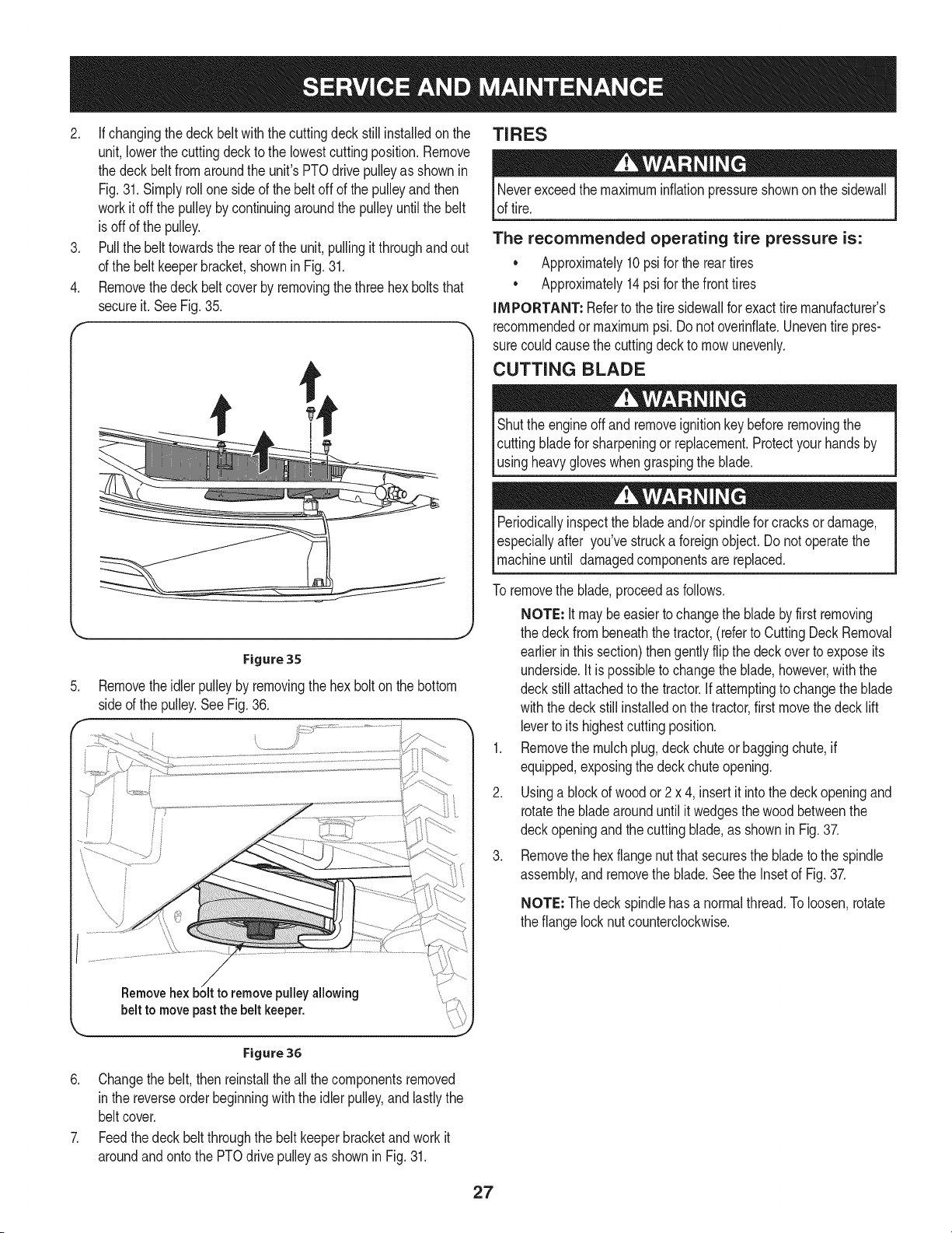
Removetheidler pulleyby removingthe hex boltonthe bottom
sideof the pulley.SeeFig.36.
pulleyallowing
belt to move pastthe belt keeper.
TIRES
Neverexceedthe maximuminflationpressureshownon the sidewall
of tire.
The recommended operating tire pressure is:
• Approximately10psifor the reartires
• Approximately14psi for thefront tires
IMPORTANT: Referto the tire sidewallfor exacttire manufacturer's
recommendedormaximumpsi.Donot overinfiate.Uneventirepres-
surecouldcausethe cuttingdeckto mowunevenly.
CUTTING BLADE
Shutthe engineoff and removeignitionkey beforeremovingthe
cuttingbladefor sharpeningor replacement.Protectyourhandsby
_usng heavygoves whengraspngthe bade.
Periodicallyinspectthe bladeand/or spindlefor cracksor damage,
especiallyafter you'vestrucka foreignobject.Do notoperatethe
machineuntil damagedcomponentsare replaced.
To removethe blade,proceedas follows.
NOTE: It maybe easiertochangethe bladebyfirst removing
the deck from beneaththetractor,(referto CuttingDeckRemoval
earlierinthis section)thengentlyflipthe deckoverto exposeits
underside.Itis possibleto changethe blade,however,withthe
deckstill attachedto the tractor.If attemptingto changethe blade
withthe deck still installedonthe tractor,firstmovethe deck lift
leverto itshighestcuttingposition.
1. Removethe mulchplug,deck chute or baggingchute,if
equipped,exposingthe deckchuteopening.
2. Usinga blockof woodor 2 x 4, insertit intothe deckopeningand
rotatethe bladearounduntilit wedgesthe woodbetweenthe
deckopeningand the cuttingblade,as shownin Fig.37.
3. Removethe hexflangenut that securesthe bladeto the spindle
assembly,and removethe blade.Seethe Insetof Fig.37.
NOTE: Thedeckspindlehasa normalthread.Toloosen,rotate
the flangelocknut counterclockwise.
Figure 36
6. Changethe belt,thenreinstallthe all the componentsremoved
in the reverseorderbeginningwith theidlerpulley,andlastlythe
beltcover.
7. Feedthedeck beltthroughthe belt keeperbracketand workit
aroundandontothe PTOdrivepulleyas shownin Fig.31.
27
.
Figure 37
Toproperlysharpenthe cuttingblades,removeequalamounts
of metalfrom bothends of the bladesalongthecuttingedges,
parallelto the trailingedge,at a 250.to 300angle.Alwaysgrind
eachcuttingbladeedge equallyto maintainproperbladebalance.
SeeFig. 38.
\
Figure 38
J
If thecuttingedge of the blade haspreviouslybeensharpened,or if
anymetalseparationis present,replacethe bladeswithnewones.
A poorlybalancedbladewill causeexcessivevibration,maycause
damageto the tractorand/orresult in personalinjury.
5. Testthe blade'sbalanceusing a bladebalancer.Grindmetal
fromthe heavy sideuntil it balancesevenly.
NOTE: Whenreplacingthe blade,besureto installthe bladewiththe
sideof the blademarked"Bottom" (or with a part numberstampedin
it) facingthe groundwhenthe moweris in theoperatingposition.
Useatorquewrenchto tightenthe bladespindlehex flangenutto
between70 Ibsift and 90 Ibsift.
ADJUSTMENTS
Neverattemptto makeanyadjustmentswhilethe engineis running,
exceptwherespecifiedin the operator'smanual.
Leveling the Deck
NOTE: Checkthe tractor'stire pressurebeforeperformingany deck
levelingadjustments.Referto Tires,in this ServiceAnd Maintenance
sectionfor moreinformationregardingtire pressure.
Front To Rear
Itis possibleto adjustthepitch of the cuttingdeck.The frontof the
deckshouldbe between0" (level)and K" lowerthanthe rear of the
deck. Adjustif necessaryasfollows:
1. Withthe tractorparkedona firm, levelsurface,placethe leverfor
liftingthe cuttingdeckintothe middleposition(3) and rotatethe
bladeso thatit is alignedwith the frontand rearof the tractor.
2. Measurethedistancefromthe front of the bladetip to the ground
andthe rearof the bladetip to theground.Thefirst measurement
takenshouldbe between0" (level)andK" lessthan the second
measurement.Determinethe approximatedistancenecessaryfor
properadjustmentand proceed,if necessary,to the nextstep.
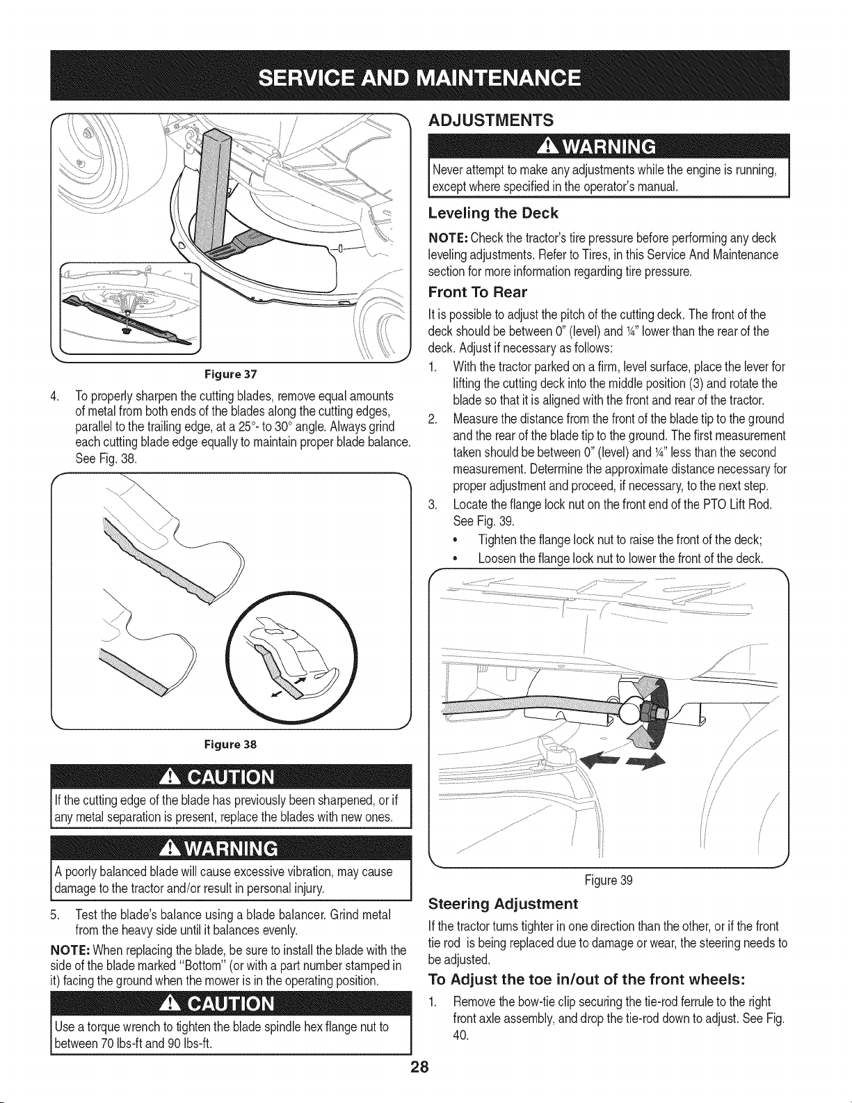
3. Locatethe flangelocknut on the frontendof the PTOLift Rod.
See Fig.39.
• Tightenthe flangelocknut to raisethe frontof the deck;
• Loosentheflangelock nutto lowerthe frontof thedeck.
/ J
/< j
//
s//
i
Figure39
Steering Adjustment
Ifthe tractorturnstighterin one directionthanthe other,or ifthe front
tie rod is being replaceddue to damageor wear,the steeringneedsto
be adjusted.
To Adjust the toe in/out of the front wheels:
1. Removethe bow-tieclip securingthe tie-rodferruleto the right
frontaxle assembly,and dropthetie-roddownto adjust.See Fig.
40.
28
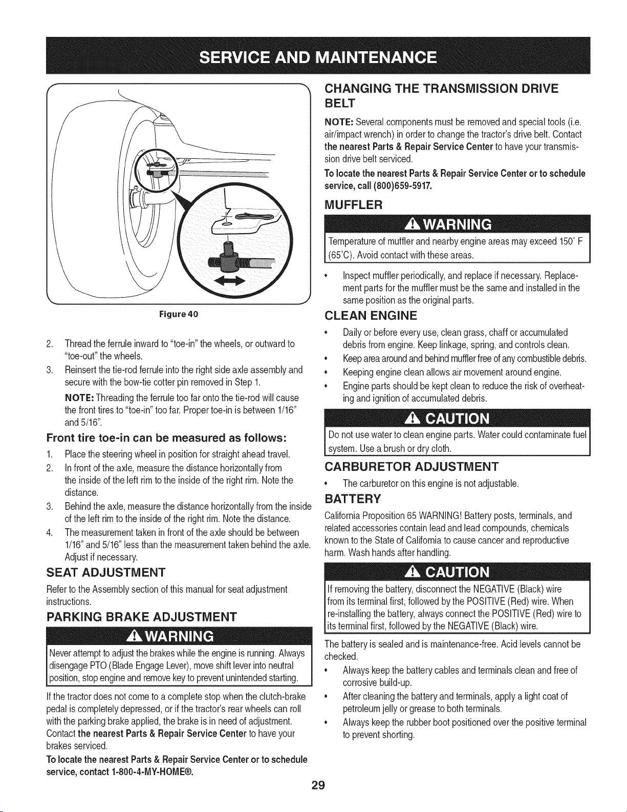
Figure 40
2. Threadthe ferruleinwardto "toe-in"the wheels,or outwardto
"toe-out"the wheels.
3. Reinsertthe tie-rodferruleintothe rightside axleassemblyand
securewiththe bow-tiecotterpin removedin Step 1.
NOTE: Threadingthe ferruletoo far ontothetie-rod willcause
the fronttires to "toe-in"too far.Propertoe-in is between1/16"
and5/16".
Front tire toe-in can be measured as follows:
1. Placethe steeringwheelin positionfor straightaheadtravel.
2. In frontof the axle,measurethedistancehorizontallyfrom
the insideof the leftrim to the insideof the rightrim.Notethe
distance.
3. Behindthe axle,measurethe distancehorizontallyfromthe inside
of the left rimto the insideof the right rim.Notethe distance.
4. Themeasurementtaken in front of theaxle shouldbe between
1/16"and 5/16"lessthanthe measurementtakenbehindthe axle.
Adjustif necessary.
SEAT ADJUSTMENT
Referto the Assemblysectionof this manualfor seatadjustment
instructions.
PARKING BRAKE ADJUSTMENT
Neverattemptto adjustthe brakeswhiletheengineis running.Always
disengagePTO(BladeEngageLever),moveshift leverintoneutral
position,stopengineandremovekeyto preventunintendedstarting.
If thetractordoes notcome to acompletestop whenthe clutch-brake
pedalis completelydepressed,orif the tractor'srear wheelscan roll
withthe parkingbrakeapplied,the brakeis in needof adjustment.
Contactthe nearest Parts & Repair Service Center to haveyour
brakesserviced.
Tolocate the nearest Parts& RepairServiceCenteror to schedule
service,contact1-800-4-MY-HOME®.
29
CHANGING THE TRANSMISSION DRIVE
BELT
NOTE: Severalcomponentsmustbe removedandspecialtools(i.e.
air/impactwrench)in orderto changethetractor'sdrivebelt.Contact
the nearest Parts& Repair Service Centerto haveyourtransmis-
siondrivebelt serviced.
Tolocatethe nearestParts& RepairServiceCenter or to schedule
service, call (800)659-5917.
MUFFLER
Temperatureof mufflerandnearbyengineareasmay exceed150° F
(65°0).Avoidcontactwiththeseareas.
• Inspectmufflerperiodically,andreplaceif necessary.Replace-
mentpartsfor the mufflermustbe the sameand installedin the
samepositionas theoriginalparts.
CLEAN ENGINE
• Dailyor beforeevery use,cleangrass,chaff or accumulated
debrisfrom engine.Keeplinkage,spring,andcontrolsclean.
• Keepareaaroundandbehindmufflerfreeof anycombustibledebris.
• Keepingenginecleanallowsair movementaroundengine.
• Enginepartsshouldbe kept cleanto reducethe riskof overheat-
ingandignitionof accumulateddebris.
Donot usewaterto cleanengineparts.Watercouldcontaminatefuel
system.Usea brushor dry cloth.
CARBURETOR ADJUSTMENT
• The carburetoron this engineis notadjustable.
BATTERY
CaliforniaProposition65 WARNING!Batteryposts,terminals,and
relatedaccessoriescontainleadandleadcompounds,chemicals
knownto the Stateof Californiato causecancerand reproductive
harm.Washhandsafterhandling.
If removingthe battery,disconnectthe NEGATIVE(Black)wire
fromitsterminalfirst,followedbythe POSITIVE(Red)wire. When
re-installingthe battery,alwaysconnectthe POSITIVE(Red)wireto
[ts termna f rst,fo owedby the NEGATVE (Back) w re.
The batteryis sealedand is maintenance-free.Acidlevelscannotbe
checked.
• Alwayskeepthe batterycablesand terminalscleanandfree of
corrosivebuild-up.
• Aftercleaningthe batteryandterminals,applya lightcoatof
petroleumjelly orgreaseto bothterminals.
• Alwayskeepthe rubberbootpositionedoverthe positiveterminal
to preventshorting.
iMPORTANT: if removingthe batteryfor any reason,disconnectthe
NEGATIVE(Black)wirefromitsterminalfirst, followedby the POSI-
TIVE(Red)wire.When re-installingthe battery,alwaysconnectthe
POSITIVE(Red) wireto itsterminalfirst,followedbythe NEGATIVE
(Black)wire.Becertainthat the wiresareconnectedto the correct
terminals;reversingthemcouldchangethe polarityandresult in
damageto yourengine'salternatingsystem.
Cleaning Battery
Cleanthe batteryby removingitfrom thetractorandwashingwith
a bakingsodaand watersolution,ifnecessary,scrapethe battery
terminalswitha wirebrushto removedeposits.Coatterminalsand
exposedwiringwithgreaseor petroleumjelly to preventcorrosion.
Battery Failures
Somecommoncausesfor batteryfailureare:
• incorrectinitialactivation
• Overcharging
• Freezing
• Undercharging
• Corrodedconnections
Thesefailuresare NOTcoveredbyyourtractor'swarranty.
JUMP STARTING
Neverjump starta damagedor frozenbattery.Be certain thevehicles
do nottouch,and ignitionsareoff. Do not allowcableclampsto
touch.
1. Connectpositive(+)cableto positivepost(+)of yourtractor's
dischargedbattery.
2. Connectthe otherend of the cableto thepositive(+)post of the
jumperbattery.
3. Connectthe secondcable negative(-) to the negativepost (-) of
thejumper battery.
4. Connectthe otherend of the negativecableto the engineblockof
the tractor,awayfromthe battery.Attachto anunpaintedpartto
assurea goodconnection.
Ifthejumperbatteryis installedon a vehicle (i.e.car, truck),do NOT
start the vehicle'senginewhenjump startingyourtractor.
5. Startthe tractor(as instructedin theOperationsectionof this
manual).
6. Setthe tractor'sparkingbrakebeforeremovingthejumpercables,
inreverseorderof connection.
CHARGING
lBatteriesgive an explosivegas charging.Charge batteryI
off while the
in a wellventilatedareaand keepawayfroman openflameor pilot I
light as ona waterheater,spaceheater,furnace,clothesdryeror
othergas app ances. 1
Whenchargingyourtractor'sbattery,useonlya chargerdesignedfor I
12Vlead-acidbatteries.Readyourbatterychargers Owners Manual
priorto chargingyourtractors battery.Alwaysfollowits instructions I
land heed ts warnngs. j
Ifyourtractorhas notbeen put intouse foran extendedperiodof time,
chargethe batteryas follows:
1. Set yourbatterychargerto delivera maxof 10amperes.
Ifyourbatterychargeris automatic,chargethebatteryuntilthe
chargerindicatesthat chargingis complete.If thechargeris not
automatic,chargefor no fewerthan eighthours.
FUSE
One15AMPfuseisinstalledinyourtractor'swiringharnesstoprotectthe
tractor'selectricalsystemfromdamagecausedbyexcessiveamperage.
Ifthe electricalsystemdoes notfunction,oryour tractor'senginewill
not crank;first checkto becertainthat thefuse has not blown.It can
be foundunderthe fenderon the leftside of the unit, on the wiring
harnessjust abovethe battery.
Alwaysusea fusewith the sameamperagecapacityfor replacement.
LUBRICATION
Beforelubricating,repairing,or inspecting,alwaysdisengagePTO
(BladeEngageLever),move shiftleverinto neutralposition,set
parkingbrake,stopengineand removekeyto preventunintended
starting.
Pivot Points & Linkage
Lubricateall the pivotpointsonthe drivesystem,parkingbrakeandlift
linkageat leastoncea seasonwith lightoil.
Rear Wheels
The rear wheelsshouldberemovedfromthe axlesonce aseason.
Lubricatethe axlesandthe rims wellwithan all-purposegreasebefore
re-installingthem.
Front Axles
Eachendofthetractor'sfrontpivotbarmaybeequippedwitha grease
fitting.Lubricatewitha greasegunafterevery25hoursof tractoroperation.
Steering Rack & Pinion
Once per season,or every 25 hoursof operation,it will benecessary
to lubricatethe steeringrackand piniongearlocatedunderthe frontof
the unit. Usingstandardautomotivegrease,applygreaseto thefront
side and rear sideof the steeringrack,as indicatedin Fig.41.
30
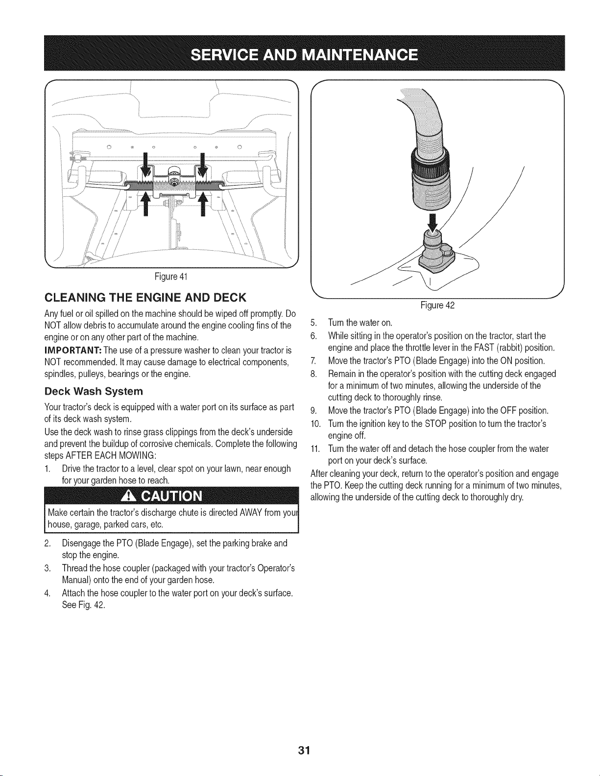
© ©
Figure41
CLEANING THE ENGINE AND DECK
Anyfuel oroil spilledonthe machineshouldbe wipedoff promptly.Do
NOTallowdebristo accumulatearoundtheenginecoolingfinsof the
engineoron anyother partof the machine.
IMPORTANT: The useof a pressurewasherto cleanyour tractoris
NOTrecommended.It maycause damageto electricalcomponents,
spindles,pulleys,bearingsor theengine.
Deck Wash System
Yourtractor'sdeck is equippedwitha waterporton its surfaceas part
of its deckwash system.
Usethedeckwashto rinsegrassclippingsfromthe deck'sunderside
andpreventthe buildupof corrosivechemicals.Completethe following
stepsAFTEREACHMOWING:
1. Drivethe tractorto a level,clearspoton your lawn,nearenough
for yourgardenhoseto reach.
Makecertainthe tractor'sdischargechuteis directedAWAYfromyour
house,garage,parkedcars,etc.
Figure42
5. Turnthewateron.
6. Whilesitting inthe operator'spositiononthe tractor,startthe
engineand placethethrottleleverin the FAST(rabbit)position.
7. Movethe tractor'sPTO(Blade Engage)intothe ON position.
8. Remainin theoperator'spositionwiththe cuttingdeckengaged
for a minimumof twominutes,allowingthe undersideof the
cuttingdeckto thoroughlyrinse.
9. Movethe tractor'sPTO(BladeEngage)intothe OFFposition.
10. Turnthe ignitionkeyto the STOPpositionto turn the tractor's
engineoff.
11. Turnthewateroff and detach thehose couplerfromthe water
portonyour deck'ssurface.
Aftercleaningyourdeck, returnto the operator'spositionandengage
the PTO. Keepthe cuttingdeckrunningfor a minimumof two minutes,
allowingthe undersideof the cuttingdeckto thoroughlydry.
2. Disengagethe PTO(BladeEngage),setthe parkingbrakeand
stoptheengine.
3. Threadthe hosecoupler(packagedwithyourtractor'sOperator's
Manual)ontothe endof yourgarden hose.
4. Attachthe hosecouplerto the waterport onyourdeck'ssurface.
SeeFig. 42.
31
Neverstorelawntractorwithfuel in tankindoorsor in poorly
ventilatedareaswherefuelfumesmay reachan open flame,spark,
or pilotlight as on a furnace,waterheater,clothesdryer,orgas
appliance.
PREPARING THE ENGINE
iMPORTANT:Fuelleft inthe fuel tankduringwarmweatherdeterio-
ratesandwill causeseriousstartingproblems.
Gasolineis a toxicsubstance.Disposeof gasolineproperly.Contact
yourlocal authoritiesfor approveddisposal methods.
Failureto usea fuel stabilizingadditiveorcompletelyrunthe engine
until it's out of fuel beforeoff-seasonstoragemay resultin damageto
yourengine'scarburetor.Subsequentdamagewouldnot be covered
underthe manufacturer'swarranty.
Enginesstoredbetween30 and 90 daysneed to betreatedwitha
gasolinestabilizerandenginesstoredover90 daysneedto bedrained
of fuelto preventdeteriorationandgum fromformingin fuel systemor
onessentialcarburetorparts. Ifthe gasolinein yourenginedeterio-
ratesduringstorage,you may needto havethe carburetor,andother
fuel systemcomponents,servicedor replaced.
Topreventgum depositsfrom forminginsidethe engine'scarburetor
andcausingpossiblemalfunctionof the engine,the fuel systemmust
beeithercompletelyemptied,or thegasolinemustbe treatedwith a
stabilizerto preventdeterioration.
1. If usingafuel stabilizer:
a. Readthe productmanufacturer'sinstructionsand recom-
mendations.
b. Add to clean,freshgasolinethe correctamountof stabilizer
forthe capacityof the fuel system.
c. Fillthe fuel tankwith treatedfueland runthe enginefor 2-3
minutesto get stabilizedfuel intothe carburetor.
2. If emptyingthefuel system:
a. Do notdrainfuel whenthe engineis hot.Allowtheengine
adequatetimeto cool. Drainfuel intoan approvedcontainer
outdoors,awayfromopenflame.
b. Drainanylargevolumeof fuelfromthe tankby disconnect-
ingthe fuel linefromthe in-linefuelfilter near theengine.
Seethecompleteinstructionsfor DrainingThe Fuellater in
thissection.
Gasolineis extremelyflammableandcan be explosiveundercertain
conditions.Draingasolinebeforestoringthe equipmentfor extended
periods.Drainfuelonly intoan approvedcontaineroutdoors,away
fromanopen flame.Allow engineto cool. Extinguishcigarettes,
cigars,pipes,andothersourcesof ignitionpriorto drainingfuel.
Storegasolinein anapprovedcontainerin safelocation.
c. Reconnectthe fuellineand runtheengineuntilit startsto
falter,then usethe choketo keepthe engine runninguntilall
fuel in the carburetorhas beenexhausted.
d. Disconnectthe fuel line and drain anyremaininggasoline
fromthe system.
32
3. Removethesparkplug and pour one (1)ounceof engineoil
throughthe spark plug holeinto thecylinder.Crankthe engine
severaltimes todistributethe oil. Replacethe sparkplug.
4. Cleandebrisfromaroundengine,underfingerguard,and under,
aroundandbehindmuffler.Touchupany damagedpaint,and
coatotherareasthatmayrustwitha light filmof oil.
5. Storeina clean, dry andwellventilatedareaawayfromany ap-
pliancethatoperateswith a flameor pilotlight,such as afurnace,
waterheater,or clothesdryer.Alsoavoidanyareawith a spark
producingelectricmotor,or wherepowertoolsare operated.
6. If possible,alsoavoidstorageareaswith highhumidity,because
thatpromotesrust and corrosion.
7. Keepthe enginelevelin storage.Tiltingcan causefuel oroil
leakage.
DRAINING THE FUEL
1. Locatethefuel filter,which islocatedon the leftside of the
engine,andmay be attachedto theenginewitha tie strap.
2. Cut the tie strap,if present,thenpinch thein-lineclampon the
fuel filterwith a pair of pliers,slidethe clampup thefuel line.
3. Pull thefuel linefree fromthe filterandplacethe openend of the
lineintoan approvedcontainerto drainthe fuel.
PREPARING THE LAWN TRACTOR
1. Cleanand lubricatethe unit thoroughlyas describedin the
Lubricationinstructionsin the ServiceandMaintenancesection.
2. Do not usea pressurewasheror garden hoseto cleanyourunit.
3. Storemowerina dry,cleanarea. Donot storenextto corrosive
materials,suchas fertilizer.
Removing From Storage
1. Checktheoil levelas describedin the Assemblysectionof this
manual.
2. If thefuel wasdrainedduringstoragepreparation,fill the tankwith
freshgasoline.If youkeepa containerof gasolinefor refueling,
makecertainitcontainsonlyfreshfuel.Gasolineoxidizesand
deterioratesovertime,causinghardstarting.
3. If thecylinderwascoatedwith oil duringstoragepreparation,the
enginewill smokebrieflyat startup.Thisis normal.
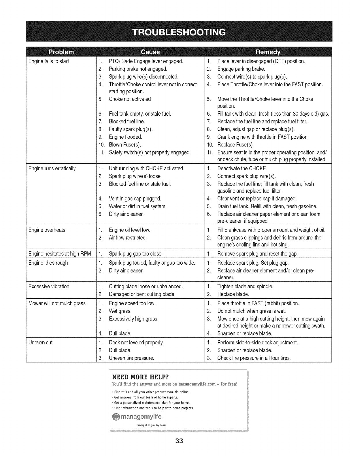
Enginefailstostart
Enginerunserratically
1. PTO/BladeEngageleverengaged.
2. Parkingbrakenotengaged.
3. Sparkplugwire(s)disconnected.
4. Throttle/ChokecontroJlevernotincorrect
startingposition.
5. Chokenotactivated
6. Fueltankempty,orstalefuel.
7. Blockedfuelline.
8. Faultysparkplug(s).
9. Engineflooded.
10.BlownFuse(s).
1. Placeleverindisengaged(OFF)position.
2. Engageparkingbrake.
3. Connectwire(s)tosparkplug(s).
4. PlaceThrottle/ChokeleverintotheFASTposition.
11.Safetyswitch(s)notproperlyengaged.
1. UnitrunningwithCHOKEactivated.
2. Sparkplugwire(s)loose.
3. Blockedfuellineorstalefuel.
5. MovetheThrottle/ChokeleverintotheChoke
position.
6. Filltankwithclean,fresh(lessthan30daysold)gas.
7. Replacethefuellineandreplacefuelfilter.
8. Clean,adjustgaporreplaceplug(s).
9. CrankenginewiththrottleinFASTposition.
10.ReplaceFuse(s)
4. Ventingascapplugged.
5. Waterordirtinfuelsystem.
6. Dirtyaircleaner.
Engineoverheats 1. Engineoillevellow. 1.
2. Airflowrestricted. 2.
EnginehesitatesathighRPM 1. Sparkpluggaptooclose. 1.
Engineidlesrough 1. Sparkplugfouled,faultyorgaptoowide. 1.
2. Dirtyaircleaner. 2.
Excessivevibration
Mowerwillnotmulchgrass
Unevencut
1. Cuttingbladelooseorunbalanced.
2. Damagedorbentcuttingblade.
1. Enginespeedtoolow.
2. Wetgrass.
3. Excessivelyhighgrass.
4. Dullblade.
1. Decknotleveledproperly.
2. Dullblade.
3. Uneventirepressure.
11.Ensureseatisintheproperoperatingposition,and/
ordeckchute,tubeormulchplugproperlyinstalled.
1. DeactivatetheCHOKE.
2. Connectsparkplugwire(s).
3. Replacethefuelline;filltankwithclean,fresh
gasolineandreplacefuelfilter.
4. Clearventorreplacecapifdamaged.
5. Drainfueltank.Refillwithclean,freshgasoline.
6. Replaceaircleanerpaperelementorcleanfoam
pre-cleaner,ifequipped.
Fillcrankcasewithproperamountandweightofoil.
Cleangrassclippingsanddebrisfromaroundthe
engine'scoolingfinsandhousing.
Removesparkplugandresetthegap.
Replacesparkplug.Setpluggap.
Replaceaircleanerelementand/orcleanpre-
cleaner.
1. Tightenbladeandspindle.
2. Replaceblade.
1. PlacethrottleinFAST(rabbit)position.
2. Donotmulchwhengrassiswet.
3. Mowonceatahighcuttingheight,thenmowagain
atdesiredheightormakeanarrowercuttingswath.
4. Sharpenorreplaceblade.
1. Performside-to-sidedeckadjustment.
2. Sharpenorreplaceblade.
3. Checktirepressureinallfourtires.
Find this and a{[ your other product manuals online.
6et answers from our team of home experts,
Get a personalized maintenance ptan for your home,
Find information and tools to help with home projects.
bzo_#_tteye_ #y S_s_
33
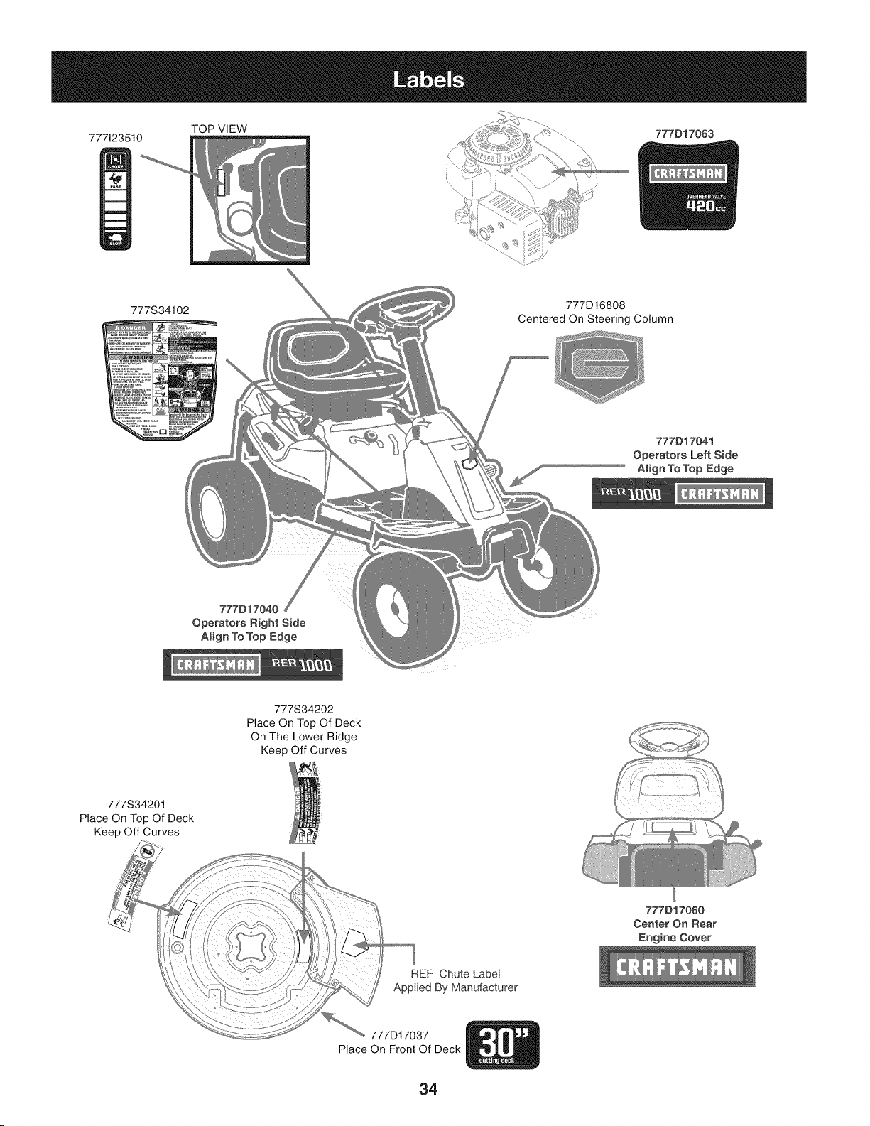
TOP VIEW
777123510 777D17063
777S34102
777D16808
Centered On Steering Column
777D17041
Operators Left Side
AJign To Top Edge
777D17040
Operators Right Side
Align To "lop Edge
777S34202
Place On Top Of Deck
On The Lower Ridge
Keep Off Curves
777S34201
Place On Top Of Deck
Keep Off Curves
REF: Chute Labe!
Applied By Manufacturer
777D17060
Center On Rear
Engine Cover
777D17037
Place On Front Of Deck
34
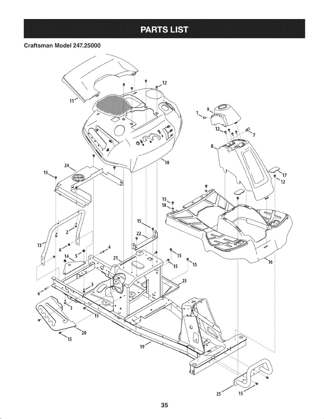
Craftsman Model 247.25000
\
24
\12
35
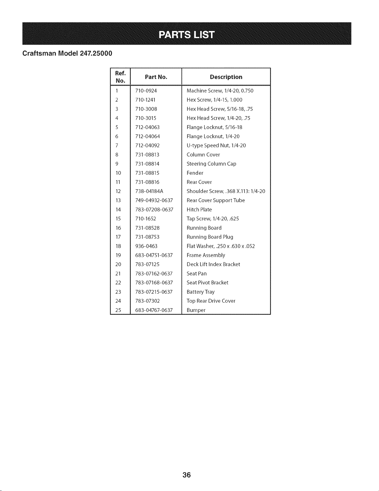
Craftsman Model 247.25000
Ref, [
No,
1 710-0924
2 710-1241
3 710-3008
4 710-3015
5 712-04063
6 712-04064
7 712-04092
8 731-08813
9 731-08814
10 731-08815
11 731-08816
12 738-04184A
13 749-04932-0637
14 783-07208-0637
15 710-1652
16 731-08528
17 731-08753
18 936-0463
19 683-04751-0637
20 783-07125
21 783-07162-0637
22 783-07168-0637
23 783-07215-0637
24 783-07302
25 683-04767-0637
Part No. Description
Machine Screw, 1/4-20, 0.750
Hex Screw, 1/4-15, 1.000
Hex Head Screw, 5/16-18, .75
Hex Head Screw, 1/4-20, .75
Flange Locknut, 5/16-18
Flange Locknut, 1/4-20
U-type Speed Nut, 1/4-20
Column Cover
Steering Column Cap
Fender
Rear Cover
Shoulder Screw, .368 X.113:1/4-20
Rear Cover Support Tube
Hitch Plate
Tap Screw, 1/4-20, .625
Running Board
Running Board Plug
Flat Washer, .250 x .630 x .052
Frame Assembly
Deck Lift Index Bracket
Seat Pan
Seat Pivot Bracket
Battery Tray
Top Rear Drive Cover
Bumper
36
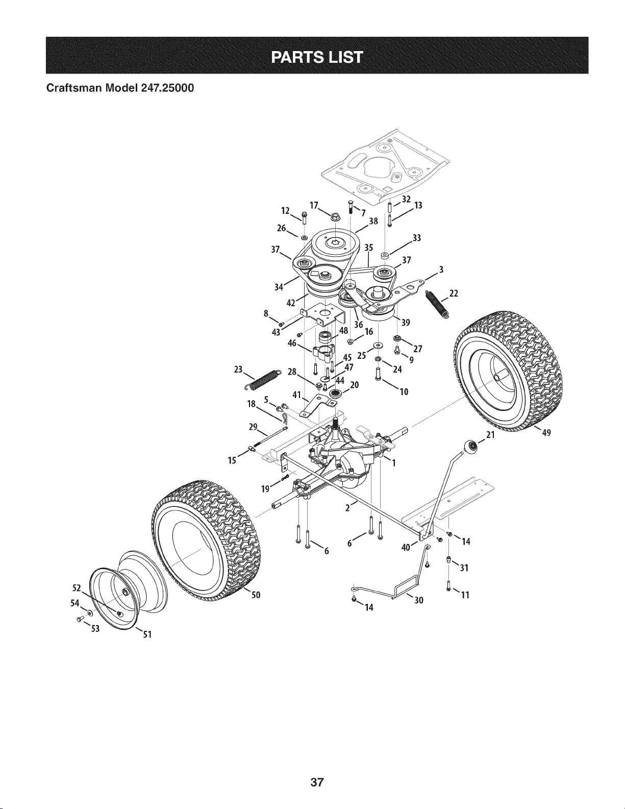
Craftsman IViodel 247.25000
37
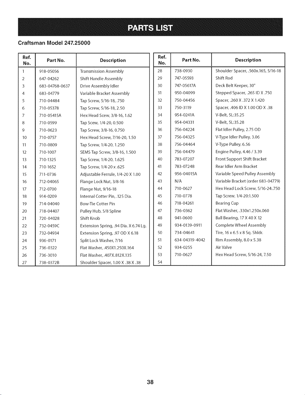
Craftsman Model 247.25000
Ref, [
No,
1 918-05056
2 647-04262
3 683-04768-0637
4 683-04779
5 710-04484
6 710-05378
7 710-05415A
8 710-0599
9 710-0623
I0 710-0757
II 710-0809
12 710-1007
13 710-1325
14 710-1652
15 711-0736
16 712-04065
17 712-0700
18 914-0209
19 714-04040
20 718-04407
21 720-04028
22 732-0459C
23 732-04934
24 936-0171
25 736-0322
26 736-3010
27 738-0372B
Part No, Description
Transmission Assembly
Shift Handle Assembly
Drive Assembly Idler
Variable Bracket Assembly
Tap Screw, 5/16-18, .750
Tap Screw, 5/16-18, 2.50
Hex Head Scew, 3/8-16, 1.62
Tap Scew, 1/4-20, 0.500
Tap Screw, 3/8-16, 0.750
Hex Head Screw, 7/16-20, 1.50
Tap Screw, 1/4-20, 1.250
SEMS Tap Screw, 3/8-16, 1.500
Tap Screw, 1/4-20, 1.625
Tap Screw, 1/4-20 x .625
Adjustable Ferrule, 1/4-20 X 1.00
Flange Lock Nut, 3/8-16
Flange Nut, 9/16-18
Internal Cotter Pin, .125 Dia.
Bow-Tie Cotter Pin
Pulley Hub, 5/8 Spline
Shift Knob
Extension Spring, .94 Dia. X 6.74 Lg.
Extension Spring, .97 OD X 6.18
Split Lock Washer, 7/16
Flat Washer, .450X1.250X.164
Flat Washer, .407X.812X.135
Shoulder Spacer, 1.00 X .38 X .38
Ref, I
NO,
28 738-0930
29 747-05593
30 747-05617A
31 950-04099
32 750-04456
33 750-3119
34 954-0241A
35 954-04331
36 756-04224
37 756-04325
38 756-04464
39 756-04479
40 783-07207
41 783-07248
42 956-04015A
43 N/A
44 710-0627
45 710-0778
46 718-04261
47 736-0362
48 941-0600
49 934-0139-0911
50 734-04641
51 634-04319-4042
52 934-0255
53 710-0627
54
Part No, Description
Shoulder Spacer, .560x.165, 5/16-18
Shift Rod
Deck Belt Keeper, 30"
Stepped Spacer, .265 ID X .750
Spacer, .260 X .372 X 1.420
Spacer, .406 ID X 1.00 OD X .38
V-Belt, 5L:35.25
V-Belt, 5L:35.28
Flat Idler Pulley, 2.75 OD
V-Type Idler Pulley, 3.06
V-Type Pulley, 6.56
Engine Pulley, 4.46 / 3.39
Front Support Shift Bracket
Rear Idler Arm Bracket
Variable Speed Pulley Assembly
Variable Bracket (order 683-04779)
Hex Head Lock Screw, 5/16-24:.750
Tap Screw, 1/4-20:1.500
Bearing Cup
Flat Washer, .330x1.250x.060
Ball Bearing, 17 X40X 12
Complete Wheel Assembly
Tire, 16 x 6.5 x 8 Sq. Shldr.
Rim Assembly, 8.0 x 5.38
Air Valve
Hex Head Screw, 5/16-24, 7.50
38
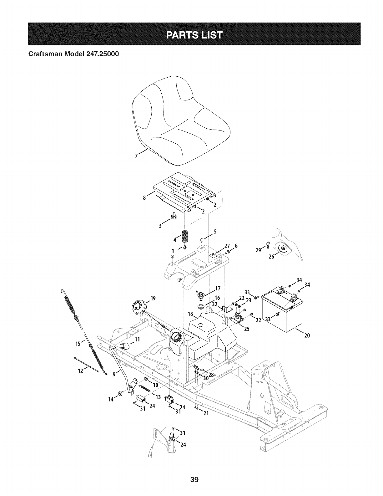
Craftsman IViodel 247.25000
11
®
22
34
34
2O
39
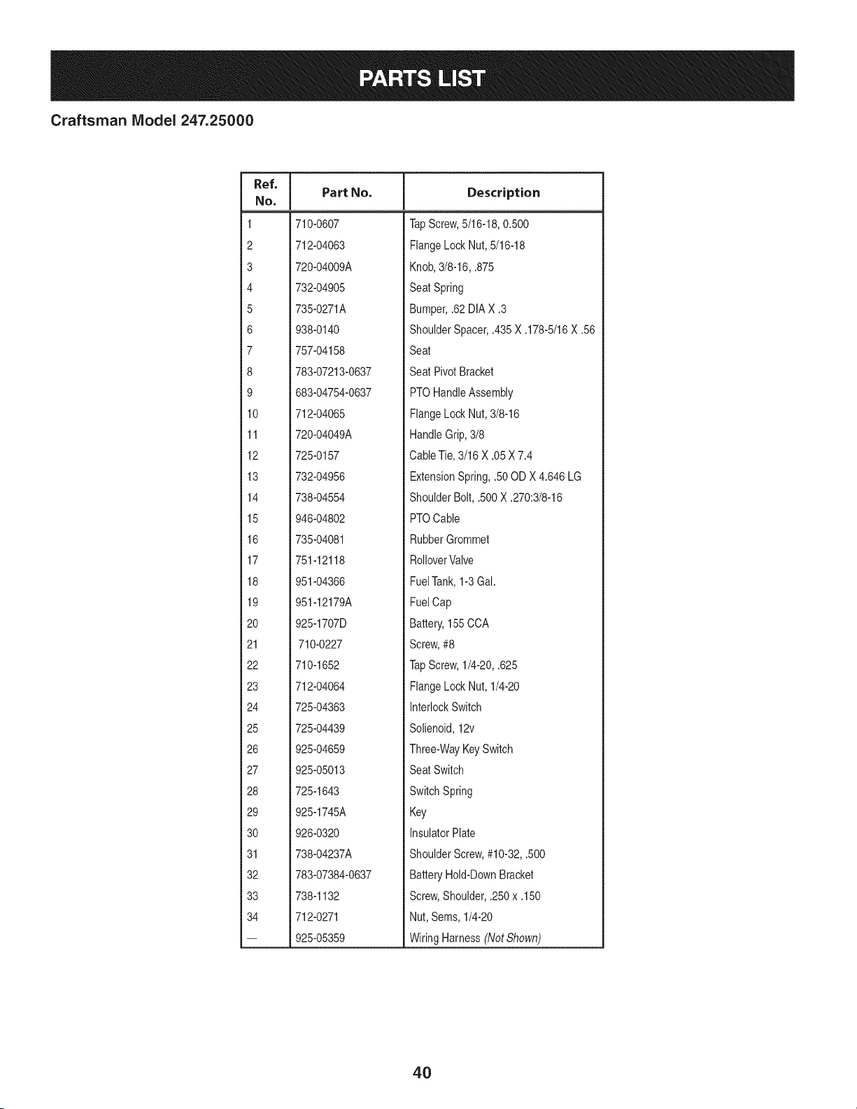
Craftsman IViodel 247.25000
Ref, I
No,
1 710-0607
2 712-04063
3 720-04009A
4 732-04905
5 735-0271A
6 938-0140
7 757-04158
8 783-07213-0637
9 683-04754-0637
10 712-04065
11 720-04049A
12 725-0157
13 732-04956
14 738-04554
15 946-04802
16 735-04081
17 751-12118
18 951-04366
19 951-12179A
20 925-1707D
21 710-0227
22 710-1652
23 712-04064
24 725-04363
25 725-04439
26 925-04659
27 925-05013
28 725-1643
29 925-1745A
30 926-0320
31 738-04237A
32 783-07384-0637
33 738-1132
34 712-0271
-- 925-05359
Part No. Description
TapScrew,5/16-18,0.500
FlangeLockNut, 5/16-18
Knob,3/8-16, .875
SeatSpring
Bumper,.62DIAX .3
ShoulderSpacer,.435X .178-5/16X .56
Seat
Seat PivotBracket
PTOHandleAssembly
FlangeLockNut, 3/8-16
HandleGrip,3/8
CableTie,3/16X .05 X 7.4
ExtensionSpring,.50OD X4.646 LG
ShoulderBolt,.500X .270:3/8-16
PTOCable
RubberGrommet
RolloverValve
FuelTank,1-3Gal.
FuelCap
Battery,155CCA
Screw,#8
TapScrew,1/4-20,.625
FlangeLockNut, 1/4-20
InterlockSwitch
Solienoid,12v
Three-WayKeySwitch
SeatSwitch
SwitchSpring
Key
InsulatorPlate
ShoulderScrew,#10-32,.500
BatteryHold-DownBracket
Screw,Shoulder,.250x .150
Nut, Sems,1/4-20
WiringHarness(Not Shown)
4O
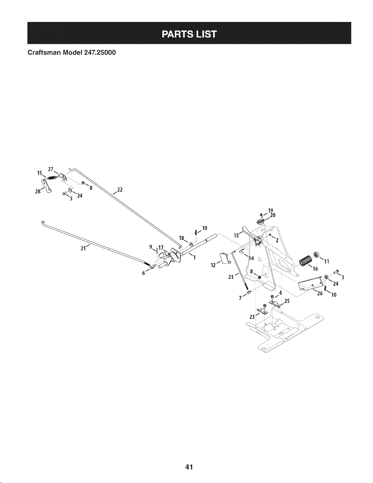
Craftsman IViodel 247.25000
15\
12
41
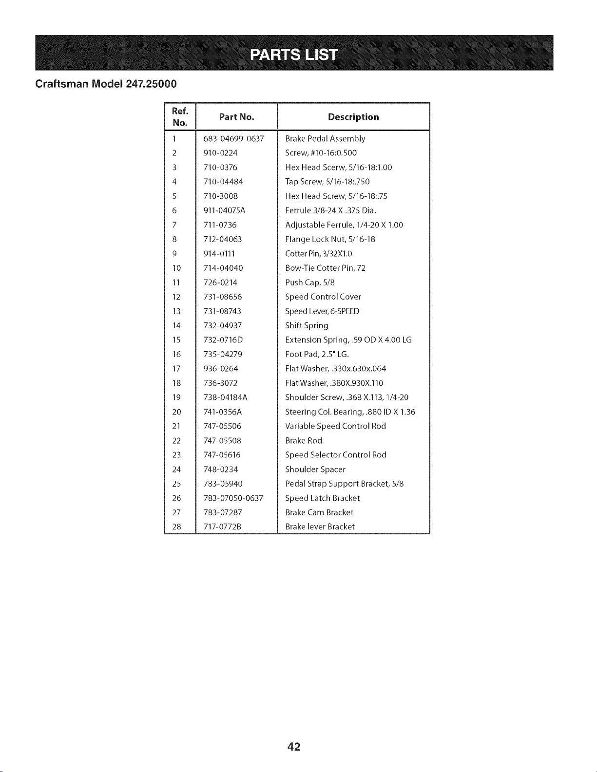
Craftsman Model 247.25000
Ref, [
No,
1 683-04699-0637
2 910-0224
3 710-0376
4 710-04484
5 710-3008
6 911-04075A
7 711-0736
8 712-04063
9 914-0111
10 714-04040
11 726-0214
12 731-08656
13 731-08743
14 732-04937
15 732-0716D
16 735-04279
17 936-0264
18 736-3072
19 738-04184A
20 741-0356A
21 747-05506
22 747-05508
23 747-05616
24 748-0234
25 783-05940
26 783-07050-0637
27 783-07287
28 717-0772B
Part No, Description
Brake Pedal Assembly
Screw, #10-16:0.500
Hex Head Scerw, 5/16-18:1.00
Tap Screw, 5/16-18:.750
Hex Head Screw, 5/16-18:.75
Ferrule 3/8-24 X .375 Dia.
Adjustable Ferrule, 1/4-20 X 1.00
Flange Lock Nut, 5/16-18
Cotter Pin, 3/32Xl .0
Bow-Tie Cotter Pin, 72
Push Cap, 5/8
Speed Control Cover
Speed Lever, 6-SPEED
Shift Spring
Extension Spring, .59 OD X 4.00 LG
Foot Pad, 2.5" LG.
Flat Washer, .330x.630x.064
Flat Washer, .380X.930X.110
Shoulder Screw, .368 X.113, 1/4-20
Steering Col. Bearing, .880 ID X 1.36
Variable Speed Control Rod
Brake Rod
Speed Selector Control Rod
Shoulder Spacer
Pedal Strap Support Bracket, 5/8
Speed Latch Bracket
Brake Cam Bracket
Brake lever Bracket
42
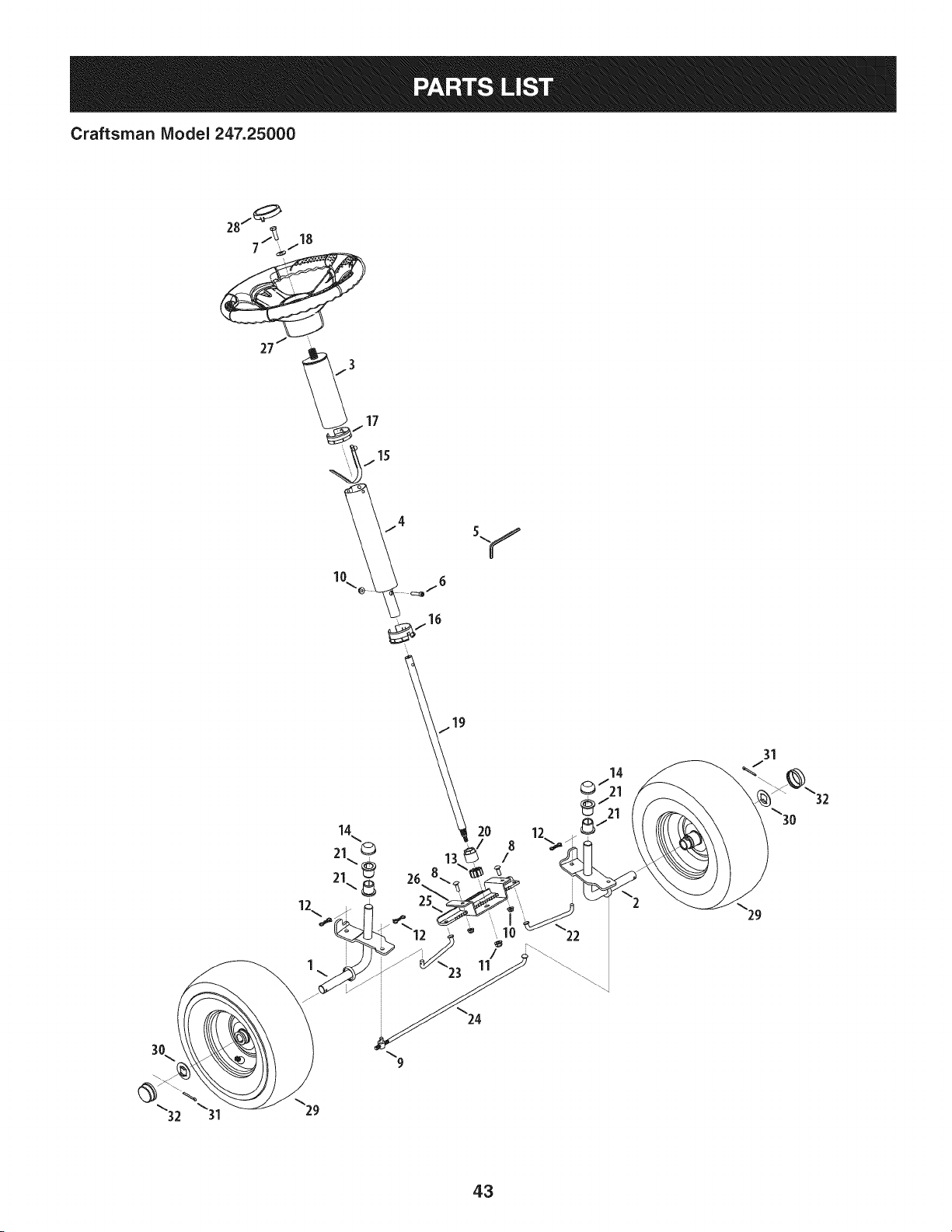
Craftsman Model 247.25000
14
21 ©
21\_
12
31
29
9
_32 \31
\29
43
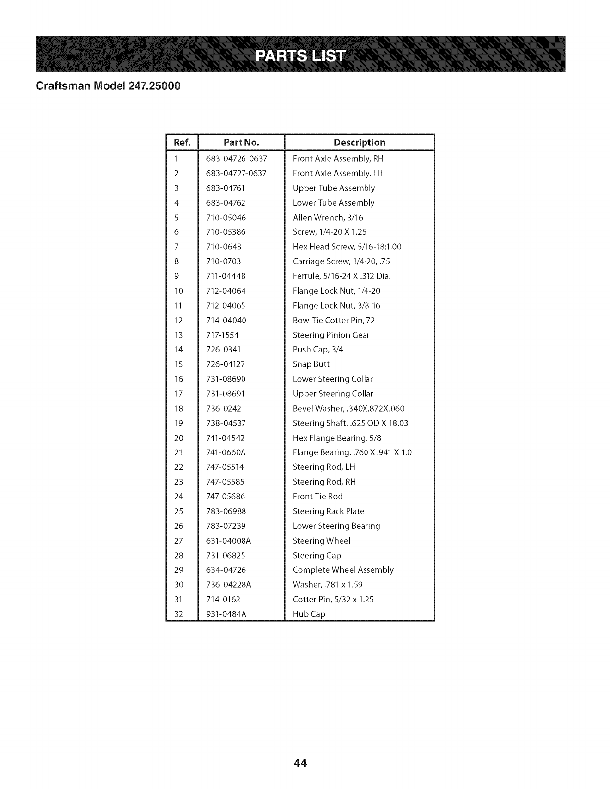
Craftsman Model 247.25000
I
Ref.
I Part No.
1 683-04726-0637
2 683-04727-0637
3 683-04761
4 683-04762
5 710-05046
6 710-05386
7 710-0643
8 710-0703
9 711-04448
10 712-04064
II 712-04065
12 714-04040
13 717-1554
14 726-0341
15 726-04127
16 731-08690
17 731-08691
18 736-0242
19 738-04537
20 741-04542
21 741-0660A
22 747-05514
23 747-05585
24 747-05686
25 783-06988
26 783-07239
27 631-04008A
28 731-06825
29 634-04726
30 736-04228A
31 714-0162
32 931-0484A
Description
Front Axle Assembly, RH
Front Axle Assembly, LH
Upper Tube Assembly
Lower Tube Assembly
Allen Wrench, 3/16
Screw, 1/4-20 X 1.25
Hex Head Screw, 5/16-18:1.00
Carriage Screw, 1/4-20, .75
Ferrule, 5/16-24 X .312 Dia.
Flange Lock Nut, 1/4-20
Flange Lock Nut, 3/8-16
Bow-Tie Cotter Pin, 72
Steering Pinion Gear
Push Cap, 3/4
Snap Butt
Lower Steering Collar
Upper Steering Collar
Bevel Washer, .340X.872X.060
Steering Shaft, .625 OD X 18.03
Hex Flange Bearing, 5/8
Flange Bearing, .760 X .941 X 1.0
Steering Rod, LH
Steering Rod, RH
Front Tie Rod
Steering Rack Plate
Lower Steering Bearing
Steering Wheel
Steering Cap
Complete Wheel Assembly
Washer, .781 x 1.59
Cotter Pin, 5/32 x 1.25
Hub Cap
44
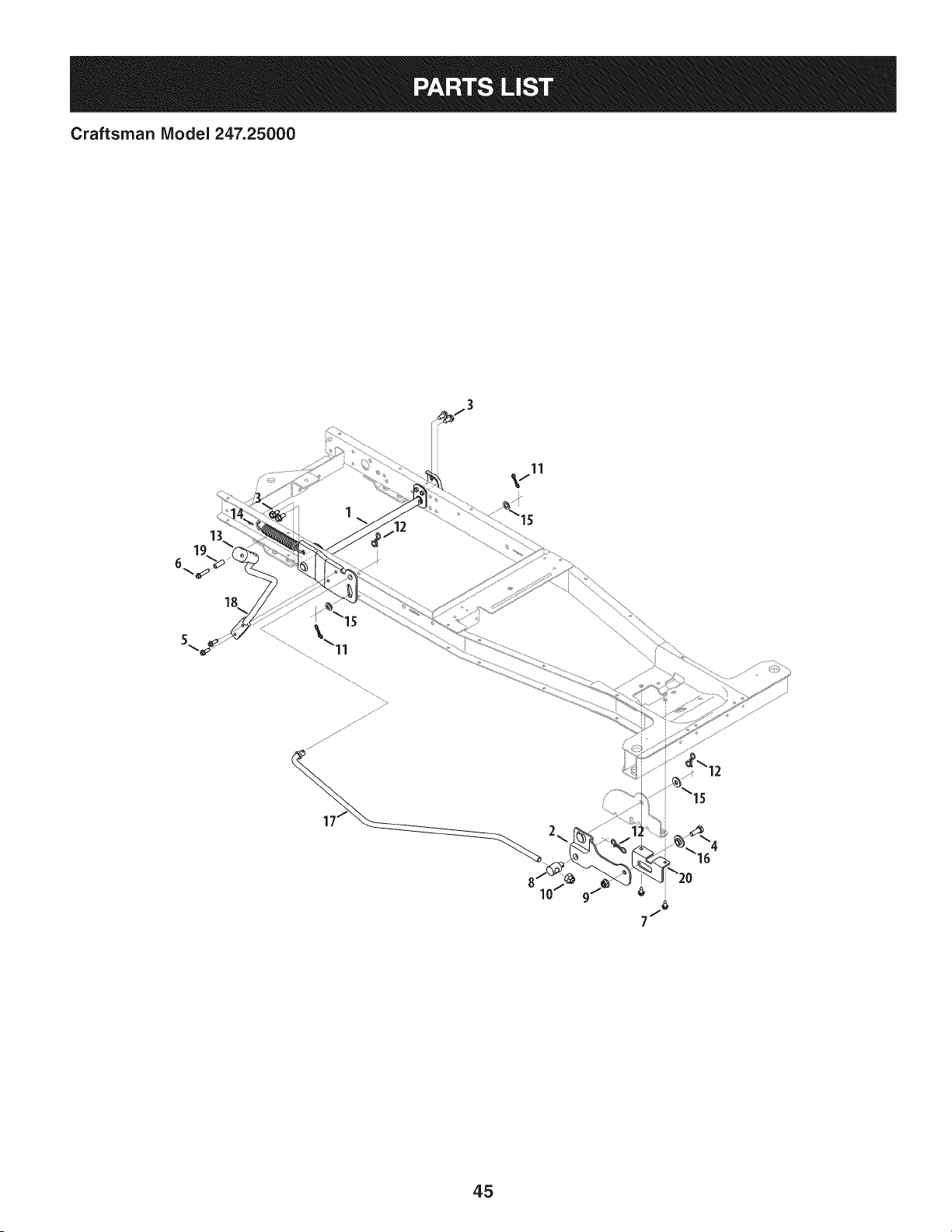
Craftsman IViodel 247.25000
11
45
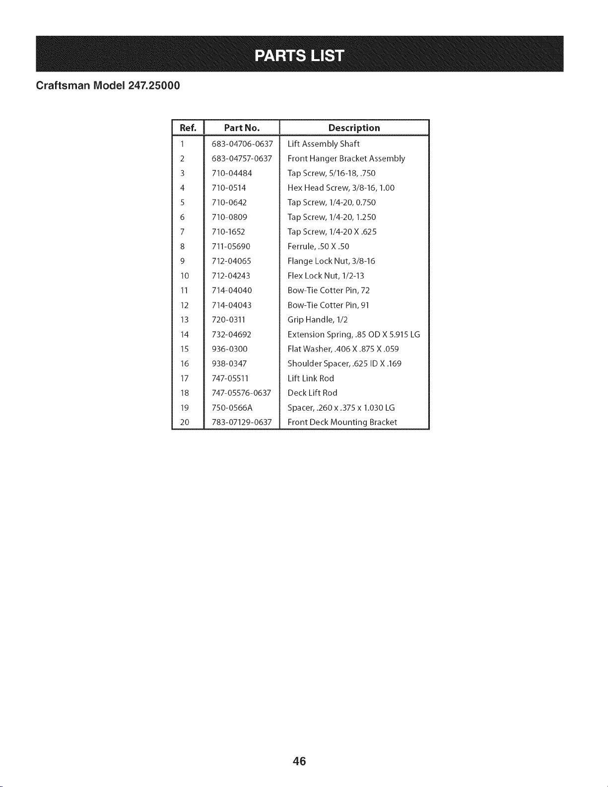
Craftsman Model 247.25000
|
Ref.
I Part No.
1 683-04706-0637
2 683-04757-0637
3 710-04484
4 710-0514
5 710-0642
6 710-0809
7 710-1652
8 711-05690
9 712-04065
10 712-04243
II 714-04040
12 714-04043
13 720-0311
14 732-04692
15 936-0300
16 938-0347
17 747-05511
18 747-05576-0637
19 750-0566A
20 783-07129-0637
Description
Lift Assembly Shaft
Front Hanger Bracket Assembly
Tap Screw, 5/16-18, .750
Hex Head Screw, 3/8-16, 1.00
Tap Screw, 1/4-20, 0.750
Tap Screw, 1/4-20, 1.250
Tap Screw, 1/4-20 X .625
Ferrule, .50 X .50
Flange Lock Nut, 3/8-16
Flex Lock Nut, 1/2-13
Bow-Tie Cotter Pin, 72
Bow-Tie Cotter Pin, 91
Grip Handle, 1/2
Extension Spring, .85 OD X 5.915 LG
Flat Washer, .406 X .875 X .059
Shoulder Spacer, .625 ID X .169
Lift Link Rod
Deck Lift Rod
Spacer, .260 x .375 x 1.030 LG
Front Deck Mounting Bracket
46
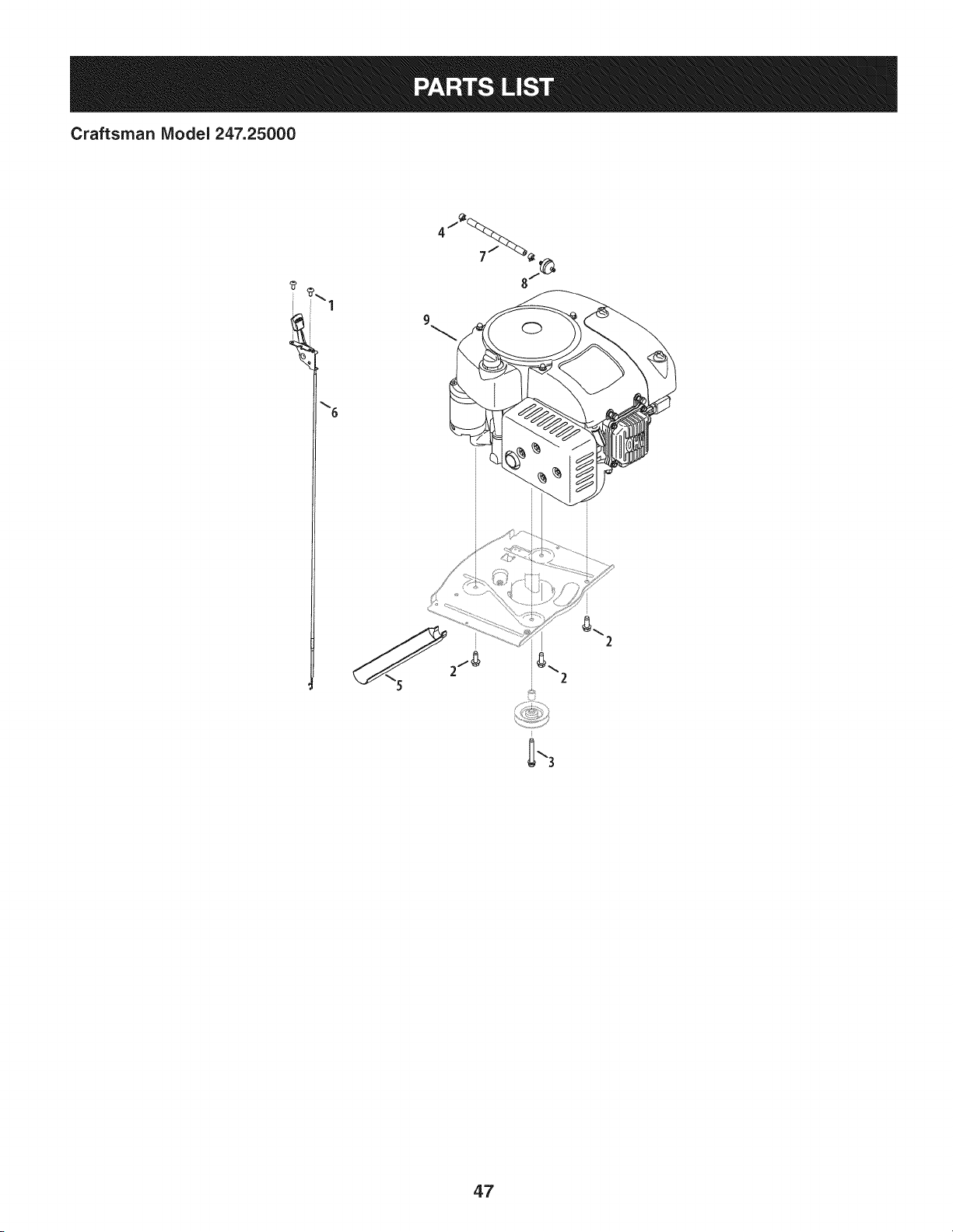
Craftsman Model 247.25000
iT-1
\6
9
2
47
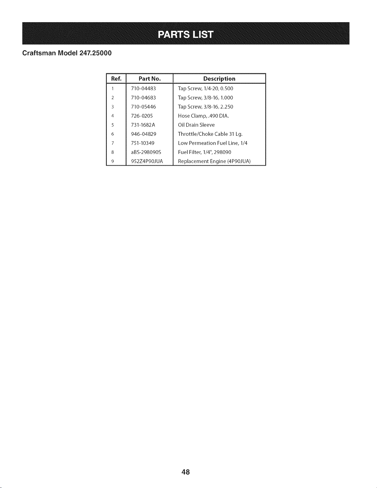
Craftsman Model 247.25000
I
Ref.
I Part No.
1 710-04483
2 710-04683
3 71O-O5446
4 726-0205
5 731-1682A
6 946-04829
7 751-10349
8 aBS-298090S
9 952Z4P90JUA
Description
Tap Screw, 1/4-20, 0.500
Tap Screw, 3/8-16, 1.000
Tap Screw, 3/8-16, 2.250
Hose Clamp, .490 DIA.
Oil Drain Sleeve
Throttle/Choke Cable 31 Lg.
Low Permeation Fuel Line, 1/4
Fuel Filter, 1/4", 298090
Replacement Engine (4P90JUA)
48
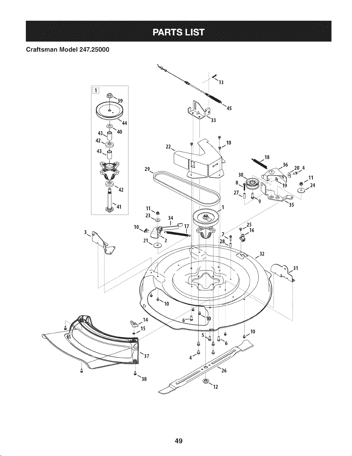
Craftsman Model 247.25000
[]
22
&\38
12
49
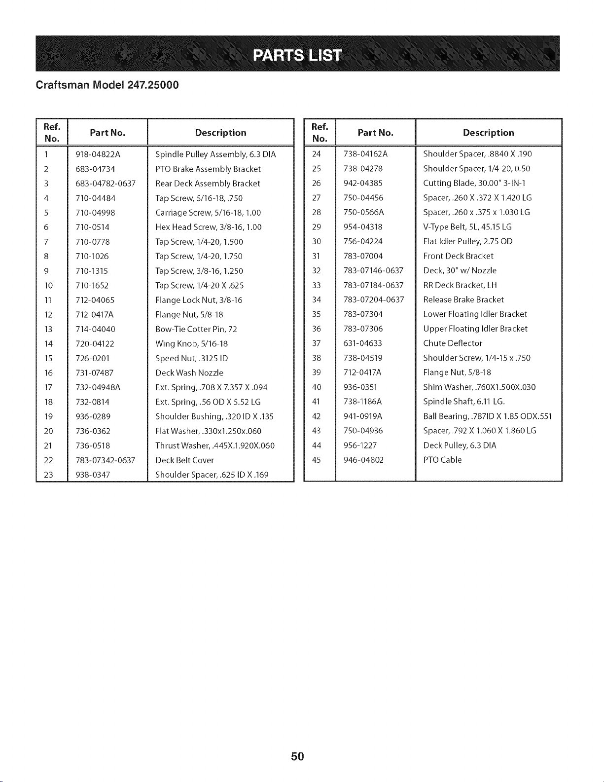
Craftsman IViodel 247.25000
Ref, I
No,
1 918-04822A
2 683-04734
3 683-04782-0637
4 710-04484
5 710-04998
6 710-0514
7 710-0778
8 710-I026
9 710-1315
10 710-1652
II 712-04065
12 712-0417A
13 714-04040
14 720-04122
15 726-0201
16 731-07487
17 732-04948A
18 732-0814
19 936-0289
20 736-0362
21 736-0518
22 783-07342-0637
23 938-0347
Part No, Description
Spindle Pulley Assembly, 6.3 DIA
PTO Brake Assembly Bracket
Rear Deck Assembly Bracket
Tap Screw, 5/16-18, .750
Carriage Screw, 5/16-18, 1.00
Hex Head Screw, 3/8-16, 1.00
Tap Screw, 1/4-20, 1.500
Tap Screw, 1/4-20, 1.750
Tap Screw, 3/8-16, 1.250
Tap Screw, 1/4-20 X .625
Flange Lock Nut, 3/8-16
Flange Nut, 5/8-18
Bow-Tie Cotter Pin, 72
Wing Knob, 5/16-18
Speed Nut, .3125 ID
Deck Wash Nozzle
Ext. Spring, .708 X 7.357 X .094
Ext. Spring, .56 OD X 5.52 LG
Shoulder Bushing, .320 ID X .135
Flat Washer, .330x1.250x.060
Thrust Washer, .445X.1.920X.060
Deck Belt Cover
Shoulder Spacer, .625 ID X .169
Ref, I
No,
24 738-04162A
25 738-04278
26 942-04385
27 750-04456
28 750-0566A
29 954-04318
30 756-04224
31 783-07004
32 783-07146-0637
33 783-07184-0637
34 783-07204-0637
35 783-07304
36 783-07306
37 631-04633
38 738-04519
39 712-0417A
40 936-0351
41 738-I186A
42 941-0919A
43 750-04936
44 956-1227
45 946-04802
Part No, Description
Shoulder Spacer, .8840 X .190
Shoulder Spacer, 1/4-20, 0.50
Cutting Blade, 30.00" 3-1N-1
Spacer, .260 X .372 X 1.420 LG
Spacer, .260 x .375 x 1.030 LG
V-Type Belt, 5L,45.15 LG
Flat Idler Pulley, 2.75 OD
Front Deck Bracket
Deck, 30" w/Nozzle
RR Deck Bracket, LH
Release Brake Bracket
Lower Floating Idler Bracket
Upper Floating Idler Bracket
Chute Deflector
Shoulder Screw, 1/4-15 x .750
Flange Nut, 5/8-18
Shim Washer, .760X1.500X.030
Spindle Shaft, 6.11 LG.
Ball Bearing, .7871D X 1.85 ODX.551
Spacer, .792 X 1.060 X 1.860 LG
Deck Pulley, 6.3 DIA
PTO Cable
5O
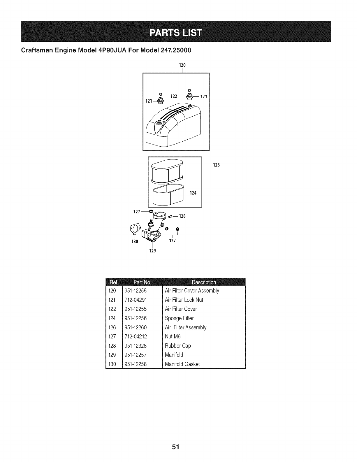
Craftsman Engine Model 4P90JUA For Model 247.25000
120
]
0
1 126
127-_o_ 01128
130 _1 127
129
m
120
121
122
124
126
127
128
129
130
951-12255
712-04291
951-12255
951-12256
951-12260
712-04212
951-12328
951-12257
951-12258
D = " O
Air FilterCoverAssembly
Air FilterLockNut
Air FilterCover
SpongeFilter
Air FilterAssembly
NutM6
RubberCap
Manifold
ManifoldGasket
51

Craftsman Engine IViodel 4P90JUA For IViodel 247.25000
7
_2
m
1
2
3
4
5
6
7
192
751-12205
712-04290
750-05320
710-05304
951-11622
710-05305
951-12206
710-05303
D = O O
DebrisShield
Nut
EngineShroudSpacer
Starter/Shroud Stud M6xlO0
FlexibleClamp
HookBolt
Air Shield
Self-TappingBolt5.5x25
52
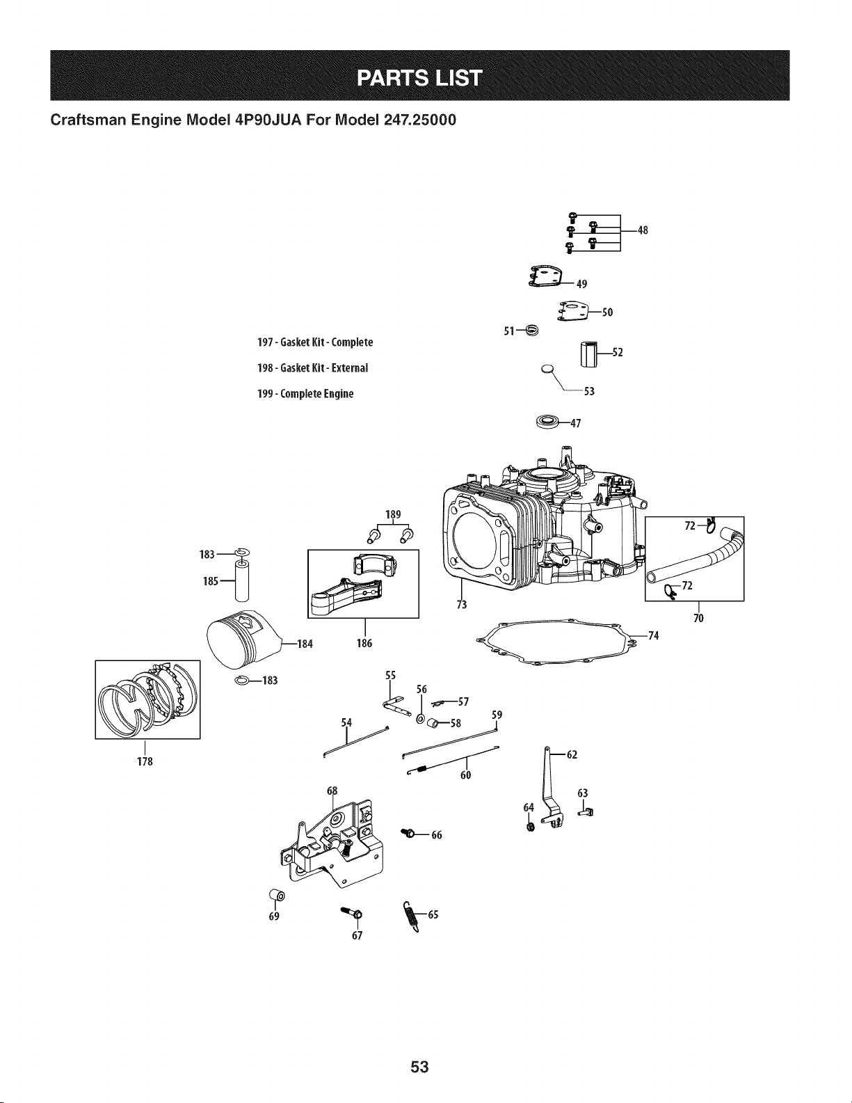
Craftsman Engine IViodel 4P90JUA For IViodel 247.25000
197-GasketI{it- Complete
198-GasketI{it- External
199-CompleteEagiae
51--_
°__53
_47
I
178
189
1_5-U
_183
55
67
I
7O
53

Craftsman Engine IViodel 4P90JUA For IViodel 247.25000
m
47
48
49
5O
51
52
53
54
55
56
57
58
59
6O
62
63
64
65
66
67
68
951-11499
710-04916
751-12770
951-12226
951-12685
951-12227
951-12686
951-12228
951-12229
736-04558
714-04074
951-11574
951-12230
951-12231
951-12232
710-04908
712-04212
951-12233
710-04979
710-05310
951-12234
D = 0
UpperCrankshaftSeal
Bolt M6x14
BreatherCoverPlate
BreatherGasket
UmbrellaValve
MeshScreen
UmbrellaValveSeat
ChokeLinkage
GovernorArm Shaft
GovernorWasher
GovernorCotterPin
GovernorSeal
ThrottleLinkage
ThrottleLinkageSpring
GovernorArm
GovernorArm Bolt
GovernorArm Nut M6
GovernorSpring
Bolt M6x18
Bolt M6x38
ThrottleControlBracket
m
69
7O
72
73
m
74
178
183
184
185
186
189
197
198
199
750-05530
951-12235
951-12236
751-12200A
951-12237
951-12275
951-11953
951-12276
951-11954
951-12277
710-05319
951-12204
951-12201
952Z4P90JUA
m = 0
ComponentBracketSpacer
BreatherHoseAssembly
BreatherHoseClamp
ShortBlockAssembly
(Incl.37,47-53,55-58,73-77,84,
86-89,91-93,98-104,112,113,
115-119,137,138,144,160,172,
173,175-178,183-186)
CrankcaseCoverGasket
PistonRingSet
PistonPinSnap Ring
Piston
PistonPin
ConnectingRodAssembly
ConnectingRodBolt
GasketKit- Complete
(Incl.47,50,58,74,113,118,
130,136-138,144,160,166)
GasketKit- External
(Inc1.113,130,136-138,144,160)
CompleteEngine(4PgOJUA)
54
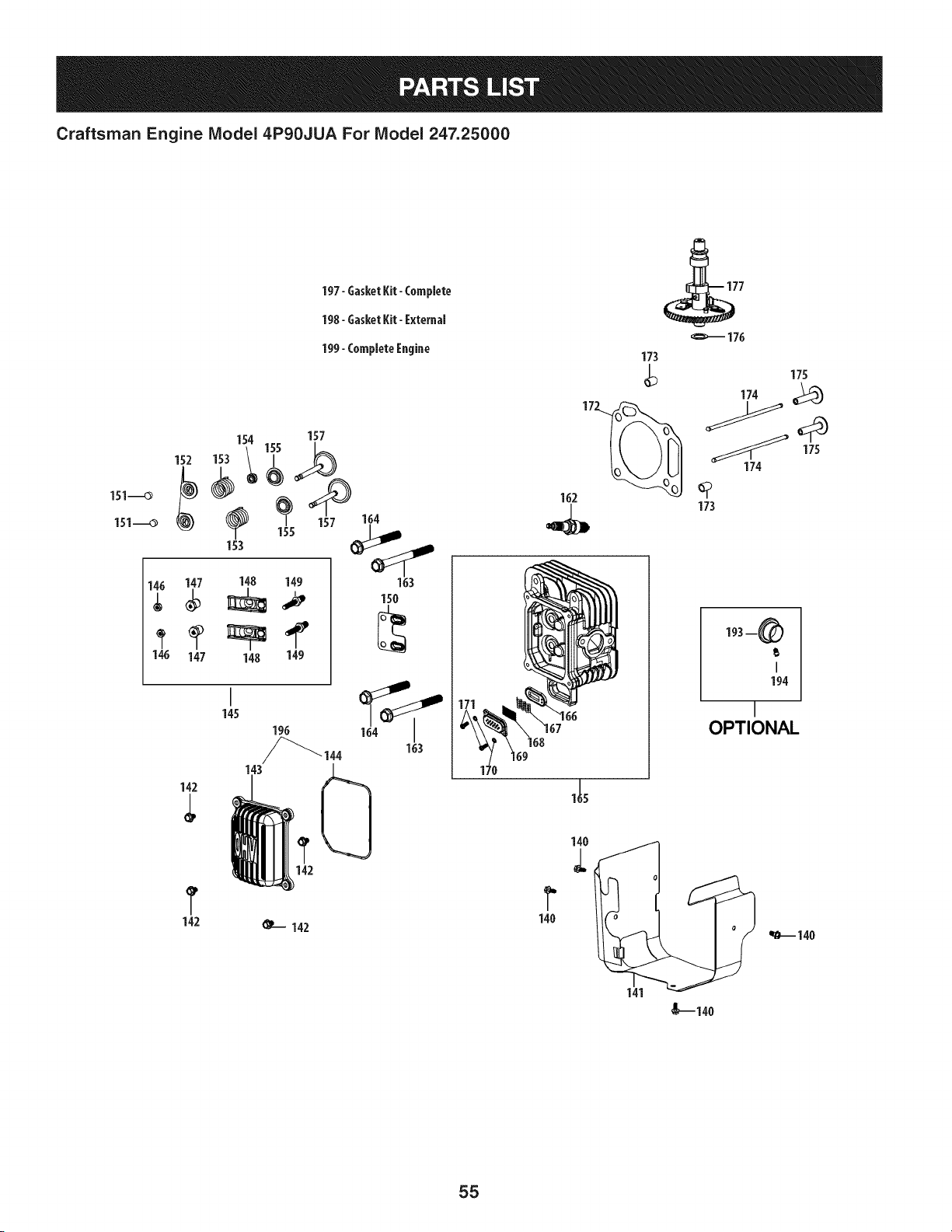
Craftsman Engine Model 4P90JUA For Model 247.25000
151-_O
151-_O
197-GasketKit- Complete
198-GasketKit- External
199- CompleteEngine
152
1A_ 147 148 149
147 148 149
154 157
153 155 _
155 16_i_
163
150
142
142
145
163
@--142
173
175
174
175
174
162 (_
173
193--_)
I
194
I
OPTIONAL
140
141
I,--14o
_140
55
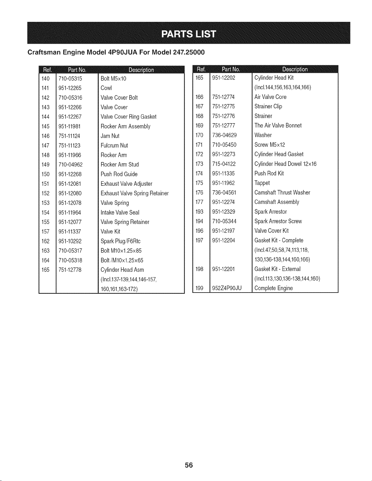
Craftsman Engine IViodel 4P90JUA For IViodel 247.25000
m
140
141
142
143
144
145
146
147
148
149
150
151
152
153
154
155
157
162
163
164
165
710-05315
951-12265
710-05316
951-12266
951-12267
951-11981
751-11124
751-11123
951-11966
710-04962
951-12268
951-12081
951-12080
951-12078
951-11964
951-12077
951-11337
951-10292
710-05317
710-05318
751-12778
D = O 0
BoltM5xlO
Cowl
ValveCoverBolt
ValveCover
ValveCoverRingGasket
RockerArmAssembly
Jam Nut
FulcrumNut
RockerArm
RockerArmStud
PushRodGuide
ExhaustValveAdjuster
ExhaustValveSpringRetainer
ValveSpring
intakeValveSeal
ValveSpringRetainer
ValveKit
SparkPlug/F6Rtc
BoltM10x1.25x85
Bolt/M10x1.25x65
CylinderHeadAsm
(Incl.137-139,144,146-157,
160,161,163-172)
m
165
166
167
168
169
170
171
172
173
174
175
176
177
193
194
196
197
198
199
951-12202
751-12774
751-12775
751-12776
751-12777
736-04629
710-05450
951-12273
715-04122
951-11335
951-11962
736-04561
951-12274
951-12329
710-05344
951-12197
951-12204
951-12201
952Z4P90JU
D = W O
CylinderHead Kit
(Inc1.144,156,163,164,166)
Air ValveCore
StrainerClip
Strainer
The Air ValveBonnet
Washer
ScrewM5x12
CylinderHeadGasket
CylinderHead Dowel12x16
PushRodKit
Tappet
CamshaftThrustWasher
CamshaftAssembly
SparkArrestor
SparkArrestorScrew
ValveCoverKit
GasketKit- Complete
(Incl.47,50,58,74,113,118,
130,136-138,144,160,166)
GasketKit- External
(Inc1.113,130,136-138,144,160)
CompleteEngine
56
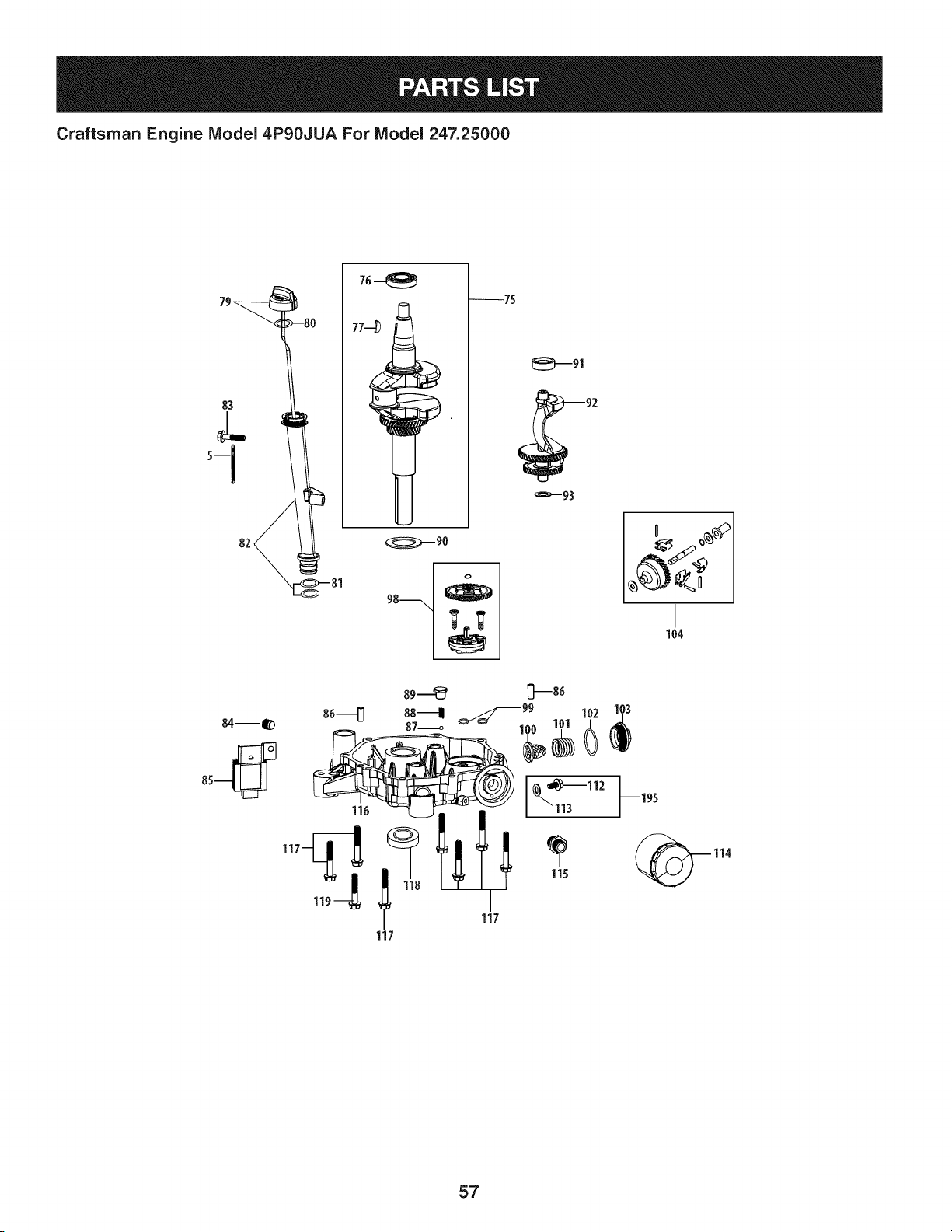
Craftsman Engine Model 4P90JUA For Model 247.25000
79_ -8{
82_ 3
76--_
--75
_----91
_---93
104
84--_
116
117
114
57
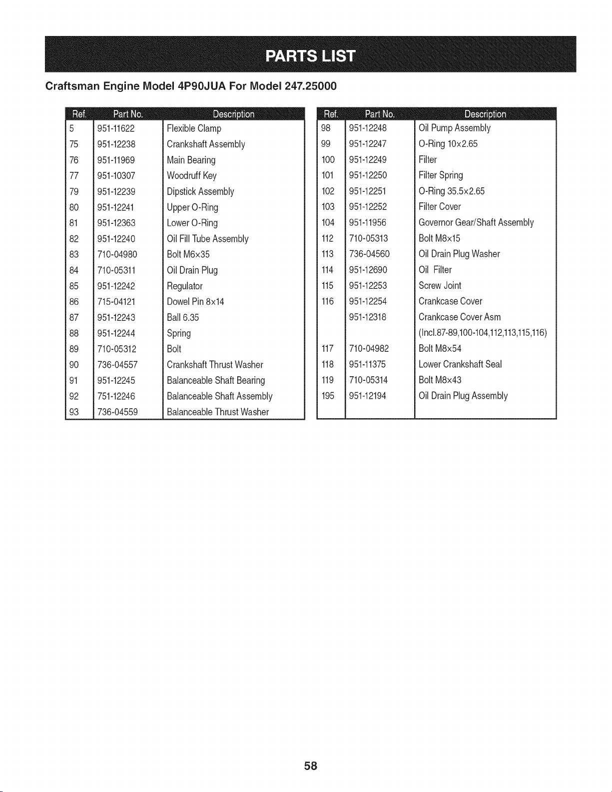
Craftsman Engine IViodel 4P90JUA For IViodel 247.25000
m
5
75
76
77
79
8O
81
82
83
84
85
86
87
88
89
9O
91
92
93
951-11622
951-12238
951-11969
951-10307
951-12239
951-12241
951-12363
951-12240
710-04980
710-05311
951-12242
715-04121
951-12243
951-12244
710-05312
736-04557
951-12245
751-12246
736-04559
D = O O
FlexibleClamp
CrankshaftAssembly
MainBearing
WoodruffKey
DipstickAssembly
UpperO-Ring
LowerO-Ring
Oil FillTubeAssembly
Bolt M6x35
Oil DrainPlug
Regulator
DowelPin8x14
Ball6.35
Spring
Bolt
CrankshaftThrustWasher
BalanceableShaftBearing
BalanceableShaftAssembly
BalanceableThrustWasher
m
98
99
1CO
101
102
103
104
112
113
114
115
116
117
118
119
195
951-12248
951-12247
951-12249
951-12250
951-12251
951-12252
951-11956
710-05313
736-04560
951-12690
951-12253
951-12254
951-12318
710-04982
951-11375
710-05314
951-12194
D = O O
OilPumpAssembly
O-Ring10x2.65
Filter
FilterSpring
O-Ring35.5x2.65
FilterCover
GovernorGear/ShaftAssembly
BoltM8x15
OilDrainPlugWasher
Oil Filter
ScrewJoint
CrankcaseCover
CrankcaseCoverAsm
(Incl.87-89,100-104,112,113,115,116)
BoltM8x54
LowerCrankshaftSeal
BoltM8x43
OilDrainPlugAssembly
58
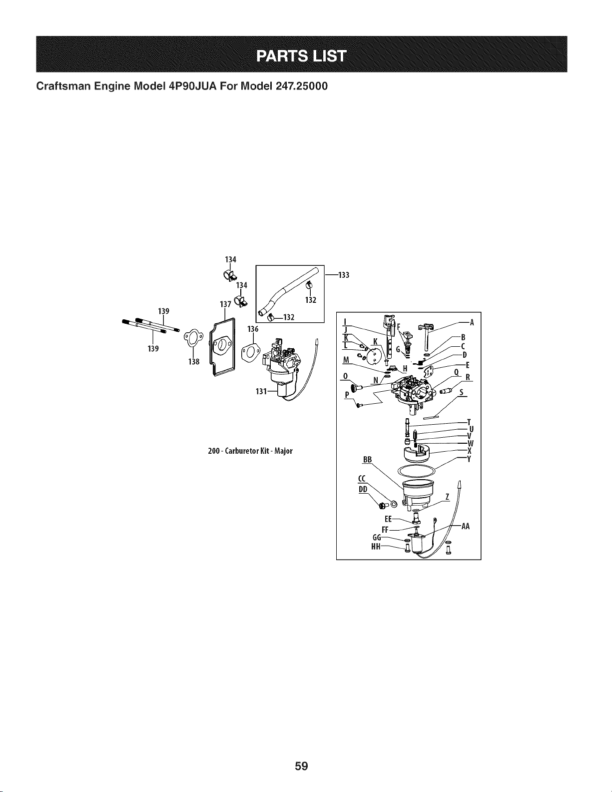
Craftsman Engine Model 4P90JUA For Model 247.25000
134
134
137
139139 138
200- CarburetorI(it- Major
--133
F A
o _ __
BB
CC
59
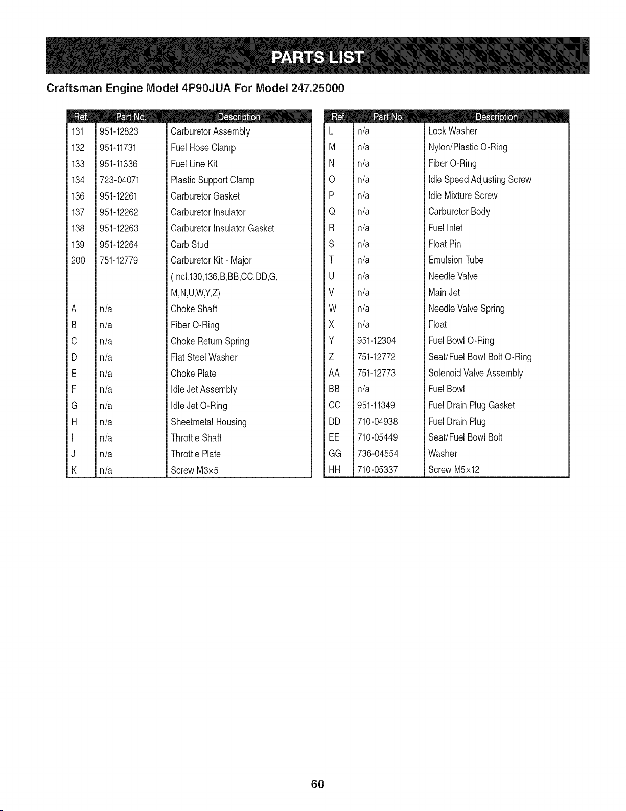
Craftsman Engine Model 4P90JUA For Model 247.25000
m
131
132
133
134
136
137
138
139
200
A
B
C
D
E
F
G
H
I
J
K
951-12823
951-11731
951-11336
723-04071
951-12261
951-12262
951-12263
951-12264
751-12779
m = I! O
CarburetorAssembly
FuelHoseClamp
FuelLineKit
PlasticSupportClamp
CarburetorGasket
CarburetorInsulator
CarburetorInsulatorGasket
CarbStud
CarburetorKit- Major
n/a
n/a
n/a
n/a
n/a
n/a
n/a
n/a
n/a
n/a
n/a
(Inck130,136,B,BB,CC,DD,G,
M,N,U,W,Y,Z)
ChokeShaft
FiberO-Ring
ChokeReturnSpring
FlatSteelWasher
ChokePlate
Idle,JetAssembly
IdleJet O-Ring
SheetmetalHousing
ThrottleShaft
ThrottlePlate
ScrewM3x5
L
M
N
0
P
Q
R
S
T
U
V
W
X
Y
Z
AA
BB
CC
DD
EE
GG
HH
n/a
n/a
n/a
n/a
n/a
n/a
n/a
n/a
n/a
n/a
n/a
n/a
n/a
951-12304
751-12772
751-12773
n/a
951-11349
710-04938
710-05449
736-04554
710-05337
D = I! O
LockWasher
Nylon/PlasticO-Ring
FiberO-Ring
IdleSpeedAdjustingScrew
IdleMixtureScrew
CarburetorBody
FuelInlet
FloatPin
EmulsionTube
NeedleValve
MainJet
NeedleValveSpring
Float
FuelBowlO-Ring
Seat/FuelBowlBoltO-Ring
SolenoidValveAssembly
FuelBowl
FuelDrainPlugGasket
FuelDrainPlug
Seat!FuelBowlBolt
Washer
ScrewM5x12
6O
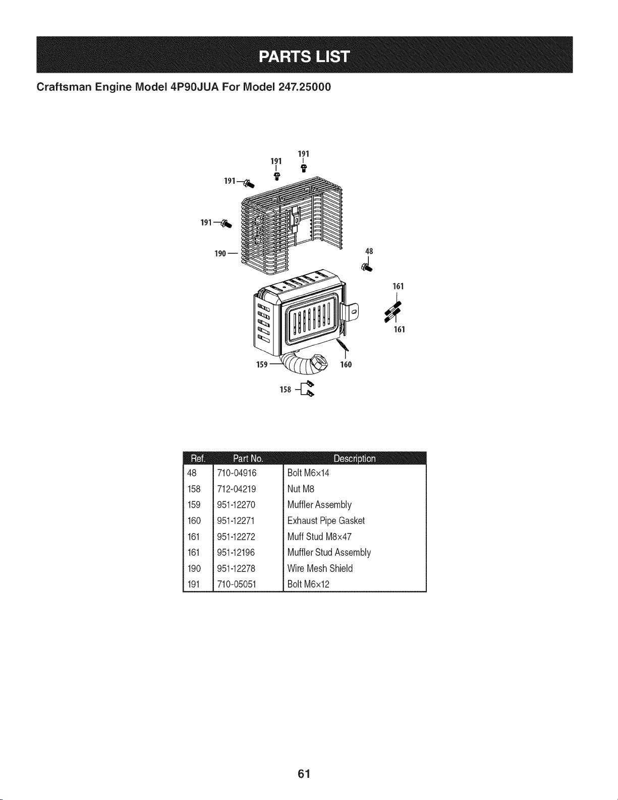
Craftsman Engine Model 4P90JUA For Model 247.25000
190 --
48
161
161
m
48
158
159
160
161
161
190
191
710-04916
712-04219
951-12270
951-12271
951-12272
951-12196
951-12278
710-05051
D = O O
BoltM6x14
NutM8
MufflerAssembly
ExhaustPipeGasket
MuffStud M8x47
MufflerStudAssembly
Wire MeshShield
BoltM6x12
61
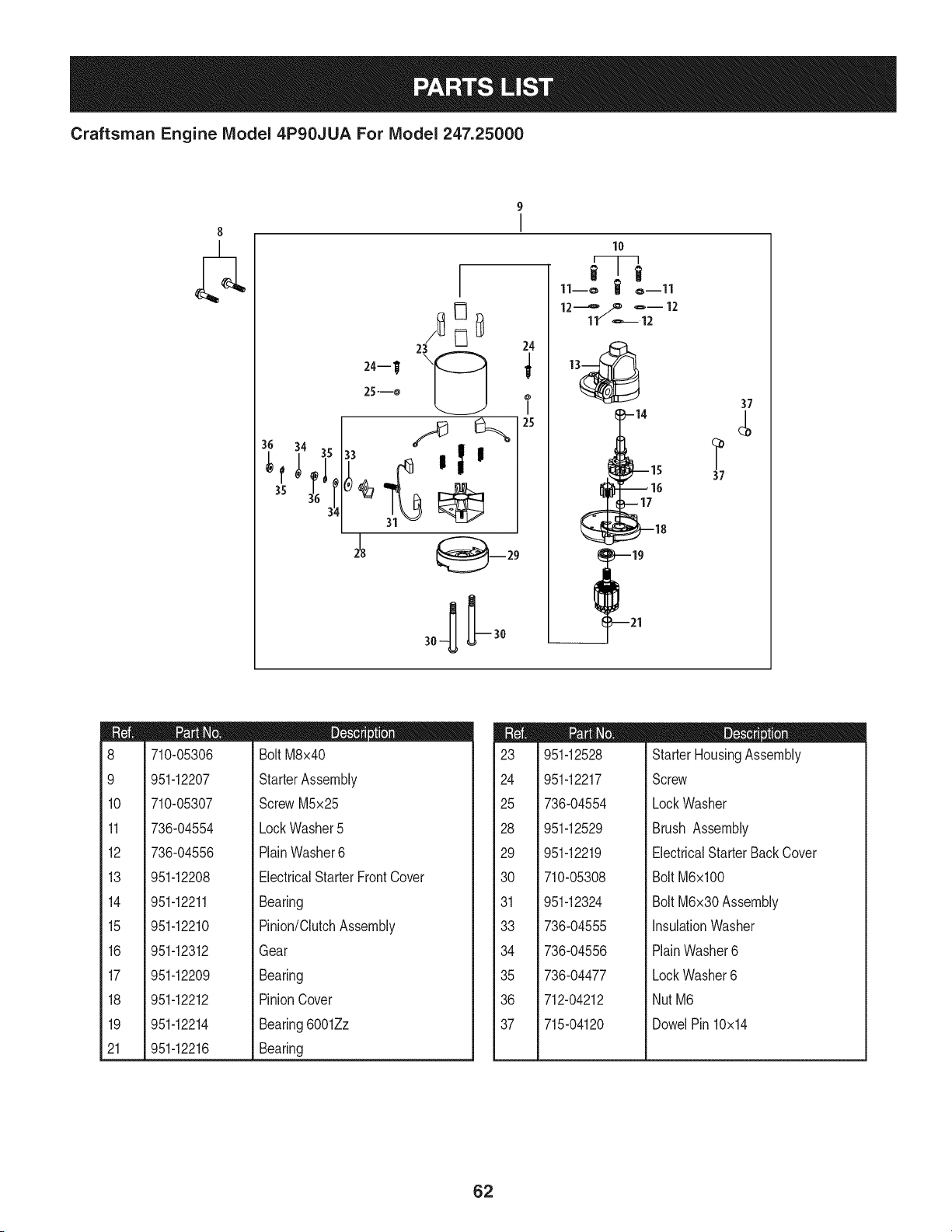
Craftsman Engine Model 4P90JUA For Model 247.25000
8
23
24--W \_
25---o
I
10
11--o | o--ll
24
I
25
_-14
_--17
37
37
m
8
9
10
11
12
13
14
15
16
17
18
19
21
710-05306
951-12207
710-05307
736-04554
736-04556
I = O
BoltM8x40
StarterAssembly
ScrewM5x25
LockWasher5
PlainWasher6
951-12208
951-12211
951-12210
951-12312
951-12209
951-12212
951-12214
951-12216
ElectricalStarterFrontCover
Bearing
Pinion/ClutchAssembly
Gear
Bearing
PinionCover
Bearing6001Zz
Bearing
m
23
24
25
28
29
30
31
33
34
35
36
37
951-12528
951-12217
736-04554
951-12529
951-12219
710-05308
951-12324
736-04555
736-04556
736-04477
712-04212
715-04120
m = O O
StarterHousingAssembly
Screw
LockWasher
Brush Assembly
ElectricalStarterBackCover
Bolt M6xl00
Bolt M6x30 Assembly
InsulationWasher
PlainWasher6
LockWasher6
NutM6
DowelPin 10x14
62
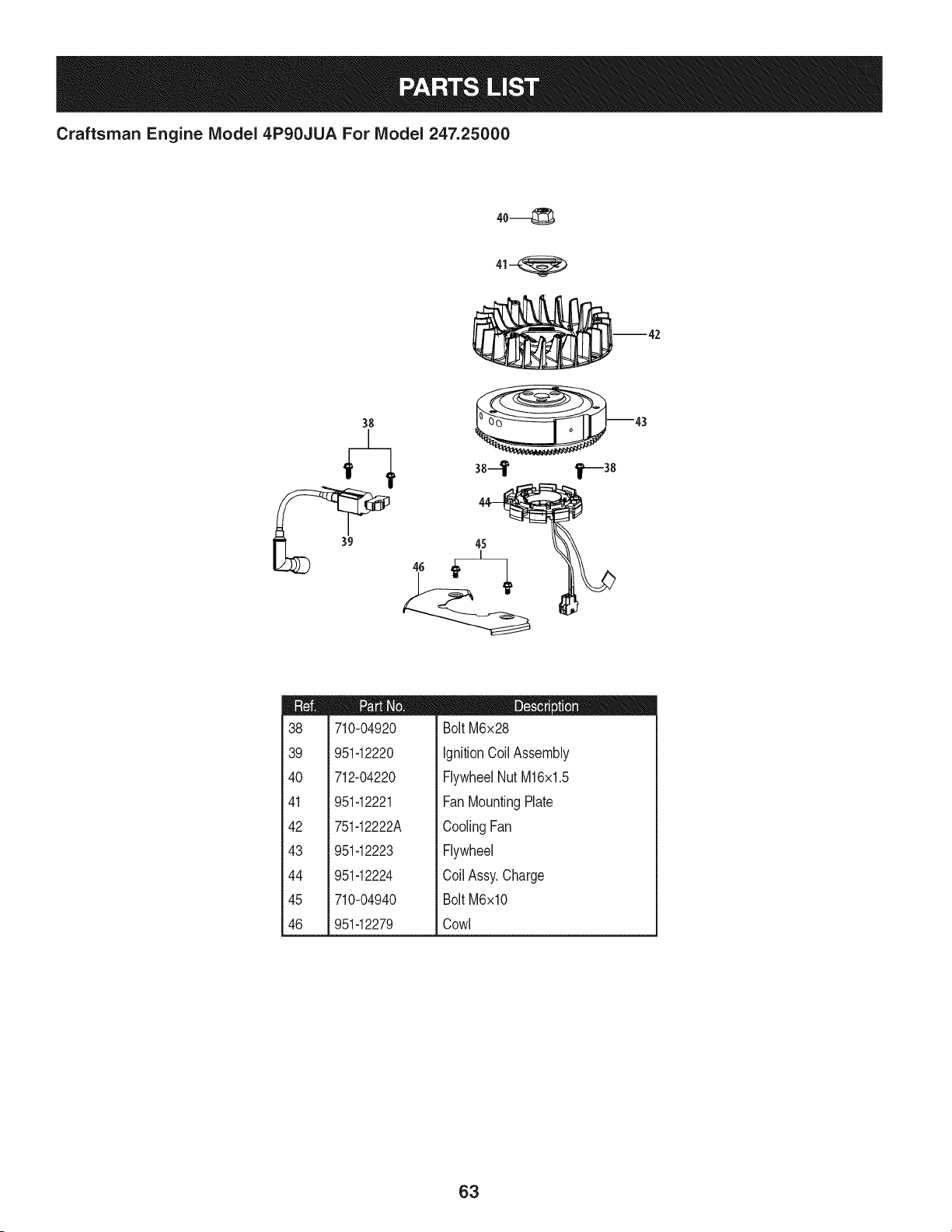
Craftsman Engine IViodel 4P90JUA For IViodel 247.25000
38
m43
38-
45
m
38
39
4O
41
42
43
44
45
46
710-04920
951-12220
712-04220
951-12221
751-12222A
951-12223
951-12224
710-04940
951-12279
D = O O
BoltM6x28
IgnitionCoil Assembly
FlywheelNutM16x1.5
FanMountingPlate
CoolingFan
Flywheel
Coil Assy.Charge
BoltM6xlO
Cowl
63
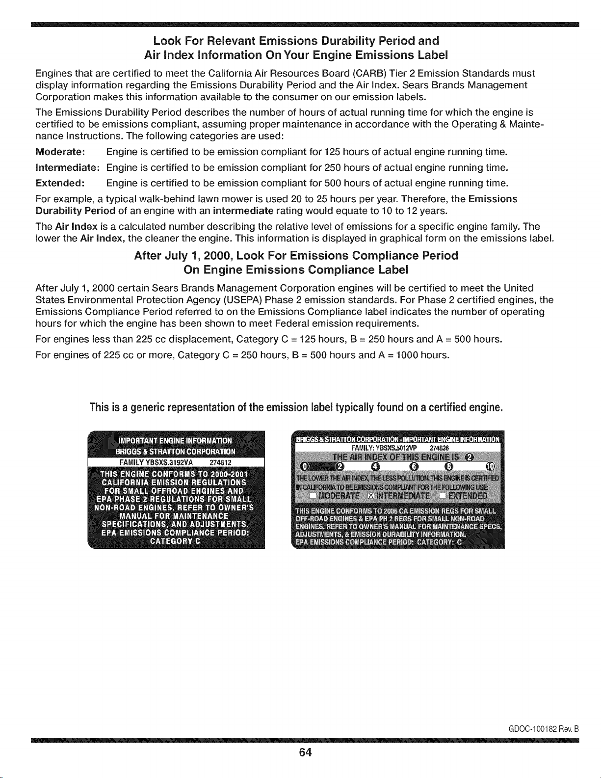
Look For Relevant Emissions Durability Period and
Air index information On Your Engine Emissions Label
Engines that are certified to meet the California Air Resources Board (CARB) Tier 2 Emission Standards must
display information regarding the Emissions Durability Period and the Air Index. Sears Brands Management
Corporation makes this information available to the consumer on our emission labels.
The Emissions Durability Period describes the number of hours of actual running time for which the engine is
certified to be emissions compliant, assuming proper maintenance in accordance with the Operating & Mainte-
nance Instructions. The following categories are used:
Moderate: Engine is certified to be emission compliant for 125 hours of actual engine running time.
Intermediate: Engine is certified to be emission compliant for 250 hours of actual engine running time.
Extended: Engine is certified to be emission compliant for 500 hours of actual engine running time.
For example, a typical walk-behind lawn mower is used 20 to 25 hours per year. Therefore, the Emissions
Durability Period of an engine with an intermediate rating would equate to 10 to 12 years.
The Air index is a calculated number describing the relative level of emissions for a specific engine family. The
lower the Air Index, the cleaner the engine. This information is displayed in graphical form on the emissions label.
After July 1,2000, Look For Emissions Compliance Period
On Engine Emissions Compliance Label
After July 1, 2000 certain Sears Brands Management Corporation engines will be certified to meet the United
States Environmental Protection Agency (USEPA) Phase 2 emission standards. For Phase 2 certified engines, the
Emissions Compliance Period referred to on the Emissions Compliance label indicates the number of operating
hours for which the engine has been shown to meet Federal emission requirements.
For engines less than 225 cc displacement, Category C = 125 hours, B = 250 hours and A = 500 hours.
For engines of 225 cc or more, Category C = 250 hours, B = 500 hours and A = 1000 hours.
This is a generic representation of the emission label typically found on a certified engine.
FAMILYYBSXS.3192VA 274812
GDOC-100182Rev.B
64
(Thispageapplicablein the U.S.A.and Canadaonly.)
Sears Brands Management Corporation (Sears), the California Air Resources Board (CARD)
and the United States Environmental Protection Agency (U.S. EPA)
Emission Control System Warranty Statement (Owner's Defect Warranty Rights and Obligations)
EMISSIONCONTROLWARRANTYCOVERAGEISAPPLICABLETOCERTI-
FIEDENGINESPURCHASEDINCALIFORNIAIN 1995ANDTHEREAF-
TER,WHICHARE USEDINCALIFORNIA,ANDTOCERTIFIEDMODEL
California and United States Emission
The CaliforniaAir ResourcesBoard(CARD),U.S.EPAand Searsare pleased
to explainthe EmissionControlSystemWarrantyon your modelyear2000and
latersmalloff-roadengine(SORE).InCalifornia,newsmall off-roadengines
mustbe designed,builtand equippedto meettheState'sstringentanti-smog
standards.Elsewherein theUnitedStates, newnon-road,spark-ignition
enginescertifiedfor modelyear 1997and latermustmeetsimilar standardsset
forth bythe U.S.EPA.Sears mustwarrantthe emissioncontrolsystemon your
YEAR 1997AND LATERENGINESWHICHARE PURCHASEDAND USED
ELSEWHEREIN THE UNITEDSTATES(ANDAFTERJANUARY1,2001 IN
CANADA).
Control Defects Warranty Statement
enginefor theperiodsoftime listedbelow,providedtherehas been noabuse,
neglector impropermaintenanceof your smalloff-roadengine.Youremis-
sion controlsystemincludespartssuch as thecarburetor,air cleaner,ignition
system,mufflerand catalyticconverter.Also includedmaybe connectorsand
otheremissionrelatedassemblies.Wherea warrantableconditionexists,Sears
will repairyour smalloff-roadengineat no costto you includingdiagnosis,parts
and labor.
Sears Emission Control Defects Warranty Coverage
Smalloff-roadenginesarewarrantedrelativeto emissioncontrol partsdefects
fora periodof one year,subjectto provisionsset forth below.Ifany covered
Owner's Warranty
Asthe smalloff-roadengine owner,you are responsiblefor the performanceof
therequiredmaintenancelistedin yourOperatingand MaintenanceInstruc-
tions.Searsrecommendsthatyou retain all yourreceiptscoveringmaintenance
on yoursmalloff-roadengine,butSears cannotdenywarrantysolelyfor the
lackof receiptsorfor yourfailureto ensuretheperformanceof all scheduled
maintenance.As the smalloff-roadengineowner,you shouldhoweverbe
awarethat Searsmay denyyou warrantycoverageifyour smalloff-roadengine
ora part hasfailed dueto abuse,neglect,impropermaintenanceor unap-
parton yourengineis defective,the part will be repairedorreplacedbySears.
Responsibilities
provedmodifications.Youare responsiblefor presentingyour smalloff-road
engineto an AuthorizedSearsServiceDealeras soonas a problemexists.The
undisputedwarrantyrepairsshouldbe completedina reasonableamountof
time,notto exceed30days. Ifyou haveany questionsregardingyourwarranty
rightsand responsibilities,you shouldcontacta SearsService Representative
at 1-800-469-4663.The emissionwarrantyis a defectswarranty.Defectsare
judgedon normalengineperformance.The warrantyis notrelatedto an in-use
emissiontest.
Sears Emission Control Defects Warranty Provisions
ThefollowingarespecificprovisionsrelativetoyourEmissionControlDefectsWarrantyCoverage.ItisinadditiontotheSearsenginewarrantyfornon-regulated
enginesfoundin the Operatingand MaintenanceInstructions.
1. WarrantedParts
Coverageunderthis warrantyextendsonly to the parts listedbelow (the
emissioncontrolsystemsparts)to the extentthese partswere presenton
theengine purchased.
a. FuelMeteringSystem
• Cold start enrichmentsystem
• Carburetorand internalparts
• FuelPump
b. Air lnduction System
• Air cleaner
• Intakemanifold
c. IgnitionSystem
• Spark plug(s)
• Magnetoignitionsystem
d. CatalystSystem
• Catalyticconverter
• Exhaustmanifold
• Air injectionsystemor pulsevalve
e. MiscellaneousItemsUsedin AboveSystems
• Vacuum,temperature,position,timesensitivevalves
andswitches
• Connectorsandassemblies
2. Lengthof Coverage
Searswarrantsto the initialownerand eachsubsequentpurchaserthat
theWarrantedPartsshallbe free from defects in materialsandworkman-
shipwhich causedthefailure of the WarrantedPartsfor a periodof one
yearfrom the datethe engineis deliveredto a retailpurchaser.
3. No Charge
Repairor replacementof anyWarrantedPartwill beperformedat no
chargeto the owner,includingdiagnosticlabor whichleads to the
determinationthata WarrantedPartis defective,ifthe diagnosticworkis
performedat an AuthorizedSears ServiceDealer.For emissionswarranty
servicecontact yournearestAuthorizedSears ServiceDealeras listed in
the "YellowPages"under"Engines,Gasoline,""GasolineEngines,""Lawn
Mowers,"or similar category.
4. Claimsand CoverageExclusions
Warrantyclaimsshall be filed in accordancewiththe provisionsof the
Sears EngineWarrantyPolicy.Warrantycoverageshall be excludedfor
failuresof WarrantedPartswhichare notoriginal Sears partsor because
of abuse, neglector impropermaintenanceas setforth inthe Sears
EngineWarrantyPolicy.Sears is not liableto coverfailuresof Warranted
Partscausedby theuse of add-on,non-original,or modifiedparts.
5. Maintenance
Any WarrantedPart whichis notscheduledfor replacementas required
maintenanceor whichis scheduledonly for regularinspectionto the effect
of "repairor replaceas necessary"shallbe warrantedas to defectsfor the
warrantyperiod.Any WarrantedPartwhich is scheduledfor replacement
as requiredmaintenanceshallbe warrantedas to defectsonly forthe
periodof time upto the firstscheduledreplacementfor that part. Any
replacementpart that is equivalentin performanceand durabilitymay
be usedin the performanceof any maintenanceor repairs.The owneris
responsibleforthe performanceof all requiredmaintenance,as definedin
the SearsOperatingand MaintenanceInstructions.
6. ConsequentialCoverage
Coveragehereundershallextend to the failure of any engine components
caused bythe failureof any WarrantedPartstill underwarranty.
Inthe USAandCanada,a 24 hour hotline, 1-800-469-4663,has a menuof pre-recordedmessagesofferingyouenginemaintenanceinformation.
GDOC-100188Rev.B
65
FEDERAL and/or CALIFORNIA EMISSION CONTROL WARRANTY STATEMENT
YOUR WARRANTY RIGHTS AND OBLIGATIONS
MTDConsumerGroupInc,the UnitedStatesEnvironmentalProtectionAgency (EPA),and, forthose productscertifiedfor sale in the stateof California,the
CaliforniaAir ResourcesBoard(CARB)are pleasedto explainthe emission(evaporativeand/or exhaust)controlsystem(ECS) warrantyon youroutdoor2006
andlater smalloff-roadspark-ignitedengine andequipment(outdoorequipmentengine)In California,new outdoorequipmentengines mustbe designed,built and
equippedto meetthe State'sstringentanti-smogstandards(in otherstates, 1997andlater modelyear equipmentmustbe designed,built, and equippedto meet
theU.S. EPAsmalloff-road, sparkignitionengine regulations.MTDConsumerGroupInc mustwarrantthe ECSon your outdoorequipmentenginefor the periodof
timelisted belowprovidedtherehas been no abuse, neglector impropermaintenanceof outdoor equipmentengine.
Your ECSmay includeparts such as the carburetor,fuel-injectionsystem,the ignitionsystem,catalyticconverter,fuel tanks,fuel lines,fuel caps, valves,canisters,
filters,vaporhoses,clamps,connectors,andotherassociatedemission-relatedcomponents.
Wherea warrantableconditionexists, MTDConsumerGroupIncwill repairyouroutdoor equipmentengine at no cost to you includingdiagnosis,parts and labor.
MANUFACTURER'S WARRANTY COVERAGE:
Thisemissioncontrolsystemis warrantedfor two years. If any emission-relatedpart on your outdoorequipmentengine is defective,the part will berepairedor
replacedby MTDCONSUMERGROUPINC.
OWNER'S WARRANTY RESPONSIBILITIES:
Asthe outdoorequipmentengineowner,you are responsiblefor performanceof the requiredmaintenancelisted inyour owner'smanual.MTDConsumerGroup
Inc recommendsthat you retain all receiptscoveringmaintenanceonyouroutdoorequipmentengine,but MTDConsumerGroupInc cannotdeny warrantysolely
forthe lackof receipts.
Asthe outdoorequipmentengineowner,you shouldhoweverbe awarethat MTDConsumerGroupInc maydenyyou warrantycoverageif your outdoorequipment
engineor a part has faileddue to abuse, neglect,or impropermaintenanceor unapprovedmodifications.
Youare responsiblefor presentingyouroutdoor equipmentengineto MTDConsumerGroupInc'sdistributioncenterorservicecenteras soon asthe problem
exists.The warrantyrepairsshouldbe completedin a reasonableamountof time, notto exceed30 days.If you havea questionregardingyour warrantycoverage,
you shouldcontactthe MTDConsumerGroup IncService Departmentat 1-800-800-7310or via email at http://support.mtdproducts.com
GENERAL EMISSIONS WARRANTY COVERAGE:
MTDConsumerGroupIncwarrantsto the ultimatepurchaserand eachsubsequentpurchaserthat the outdoorequipmentengineis: Designed,built and equipped
so asto conformwithall applicableregulations;and freefrom defects in materialsand workmanshipthatcausethe failureof a warrantedpart to be identicalin all
materialrespectsto that part as describedin MTDConsumerGroup Inc'sapplicationfor certification.
The warrantyperiodbeginson thedate theoutdoorequipmentengineis deliveredto an ultimatepurchaserorfirst placedinto service.The warrantyperiodis two
years.
Subjectto certainconditionsand exclusionsasstated below,the warrantyon emission-relatedparts is asfollows:
1. Any warrantedpart that is notscheduledfor replacementas requiredmaintenancein thewritten instructionssupplied,is warrantedforthe warrantyperiod
statedabove. Ifthe part fails duringthe periodof warrantycoverage,the part will berepairedor replacedbyMTDConsumerGroupInc accordingto subsection
(4) below. Anysuch part repairedor replacedunderwarrantywillbe warrantedfor the remainderof the period.
2. Any warrantedpart that is scheduledonly for regularinspectionin the writteninstructionssupplied is warrantedforthe warrantyperiodstatedabove.Any such
part repairedor replacedunderwarrantywill bewarrantedforthe remainingwarrantyperiod.
3. Any warrantedpart that is scheduledfor replacementas requiredmaintenancein thewritten instructionssuppliedis warrantedfor the periodof time beforethe
first scheduledreplacementdatefor that part. If the partfails beforethefirst scheduledreplacement,the part will berepairedorreplacedby MTDConsumer
GroupInc accordingto subsection(4) below.Any such part repairedor replacedunderwarrantywill bewarrantedfor the remainderof the periodpriorto the
first scheduledreplacementpointfor the part.
4. Repairor replacementof any warrantedpart underthe warrantyprovisionshereinmustbe performedat a warrantystationat no chargeto the owner.
5. Notwithstandingthe provisionsherein,warrantyservicesor repairswill be providedat all of our distributioncentersthatare franchisedto servicethe subject
enginesor equipment.
6. The outdoorequipmentengine ownerwill notbe chargedfor diagnosticlaborthat is directlyassociatedwithdiagnosisof a defective,emission-relatedwar-
rantedpart, providedthat suchdiagnosticworkis performedat a warrantystation.
7. MTDConsumerGroupInc is liablefor damagesto otherengine or equipmentcomponentsproximatelycausedby a failure underwarrantyof any warranted
part.
8. Throughoutthe off-roadengineand equipmentwarrantyperiodstatedabove, MTDConsumerGroupInc will maintaina supply of warrantedparts sufficientto
meetthe expecteddemandfor such parts.
9. Any replacementpart maybe usedinthe performanceof any warrantymaintenanceor repairsand mustbe providedwithoutchargeto the owner.Suchuse will
notreducethe warrantyobligationsof MTDConsumerGroupInc.
10.Add-onor modifiedpartsthat are not exemptedbythe Air ResourcesBoardmay not beused.The use of any non-exemptedadd-onor modifiedparts by the
ultimatepurchaserwill be groundsfor disallowinga warrantyclaims. MTDConsumerGroup Incwill not be liable to warrantfailuresof warrantedparts caused
bythe useof a non-exemptedadd-onor modifiedpart.
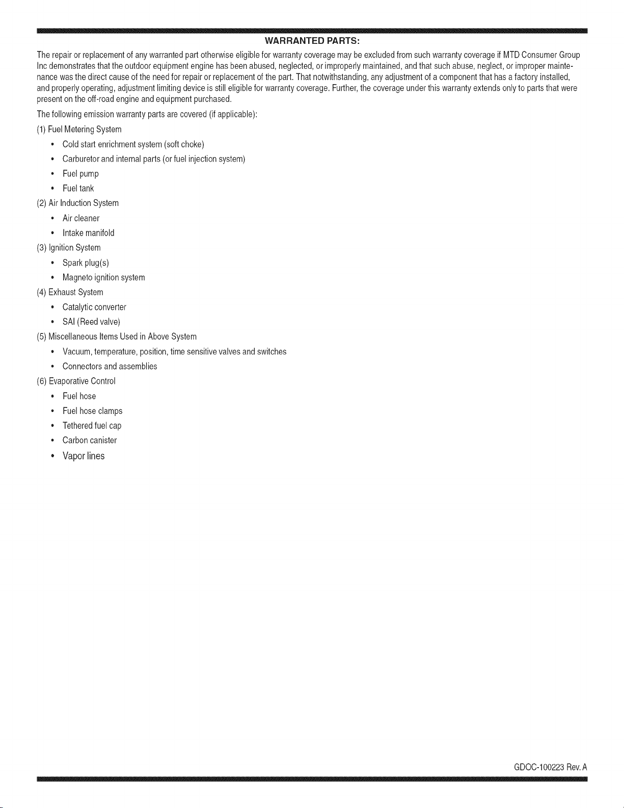
WARRANTED PARTS:
The repairor replacementof any warrantedpart otherwiseeligiblefor warrantycoveragemaybe excludedfrom such warrantycoverageif MTDConsumerGroup
Inc demonstratesthatthe outdoor equipmentenginehas beenabused,neglected,or improperlymaintained,and that suchabuse,neglect,or impropermainte-
nancewasthe direct causeof the needfor repairor replacementof the part.That notwithstanding,any adjustmentof a componentthat hasa factory installed,
andproperlyoperating,adjustmentlimitingdeviceis still eligible for warrantycoverage. Further,the coverageunderthis warrantyextendsonly to partsthat were
presenton the off-roadengineand equipmentpurchased.
Thefollowing emissionwarrantypartsare covered(if applicable):
(1) FuelMeteringSystem
• Cold start enrichmentsystem(softchoke)
• Carburetorand internalparts (or fuel injectionsystem)
• Fuelpump
• Fueltank
(2) Air InductionSystem
• Air cleaner
• Intakemanifold
(3) IgnitionSystem
• Sparkplug(s)
• Magnetoignitionsystem
(4) ExhaustSystem
• Catalyticconverter
• SAI(Reed valve)
(5) MiscellaneousItemsUsedin AboveSystem
• Vacuum,temperature,position,timesensitivevalvesand switches
• Connectorsandassemblies
(6) EvaporativeControl
• Fuelhose
• Fuelhoseclamps
• Tetheredfuel cap
• Carboncanister
• Vapor lines
GDOC-100223Rev.A

Congratulations on making a smart purchase. Your new Craftsman® product is designed and
manufactured for years of dependable operation. But like all products, it may require repair
from time to time. That's when having a Repair Protection Agreement can save you money and
aggravation.
Here's what the Repair Protection Agreement* includes:
[] Expert service by our 10,000 professional repair specialists
[] Unlimited service and no charge for parts and labor on all covered repairs
[] Product replacement up to $1500 if your covered product can't be fixed
[] Discount of 25% from regular price of service and related installed parts not covered by the
agreement; also, 25% off regular price of preventive maintenance check
[] Fast help by phone - we call it Rapid Resolution - phone support from a Sears representative.
Think of us as a "talking owner's manual."
Once you purchase the Repair Protection Agreement, a simple phone call is all that it takes for you
to schedule service. You can call anytime day or night, or schedule a service appointment online.
The Repair Protection Agreement is a risk-free purchase. If you cancel for any reason during the
product warranty period, we will provide a full refund. Or, a prorated refund anytime after the
product warranty period expires. Purchase your Repair Protection Agreement today!
Some limitations and exclusions apply. For prices and additional information in the U.S.A.
call 1=800=827=6655.
*Coverage in Canada varies on some items. For full details call Sears Canada at 1=800=361=
6665.
Sears Installation Service
For Sears professional installation of home appliances, garage door openers, water heaters, and
other major home items, in the U.S.A. or Canada call 1=800=4=MY=HOME®.
68
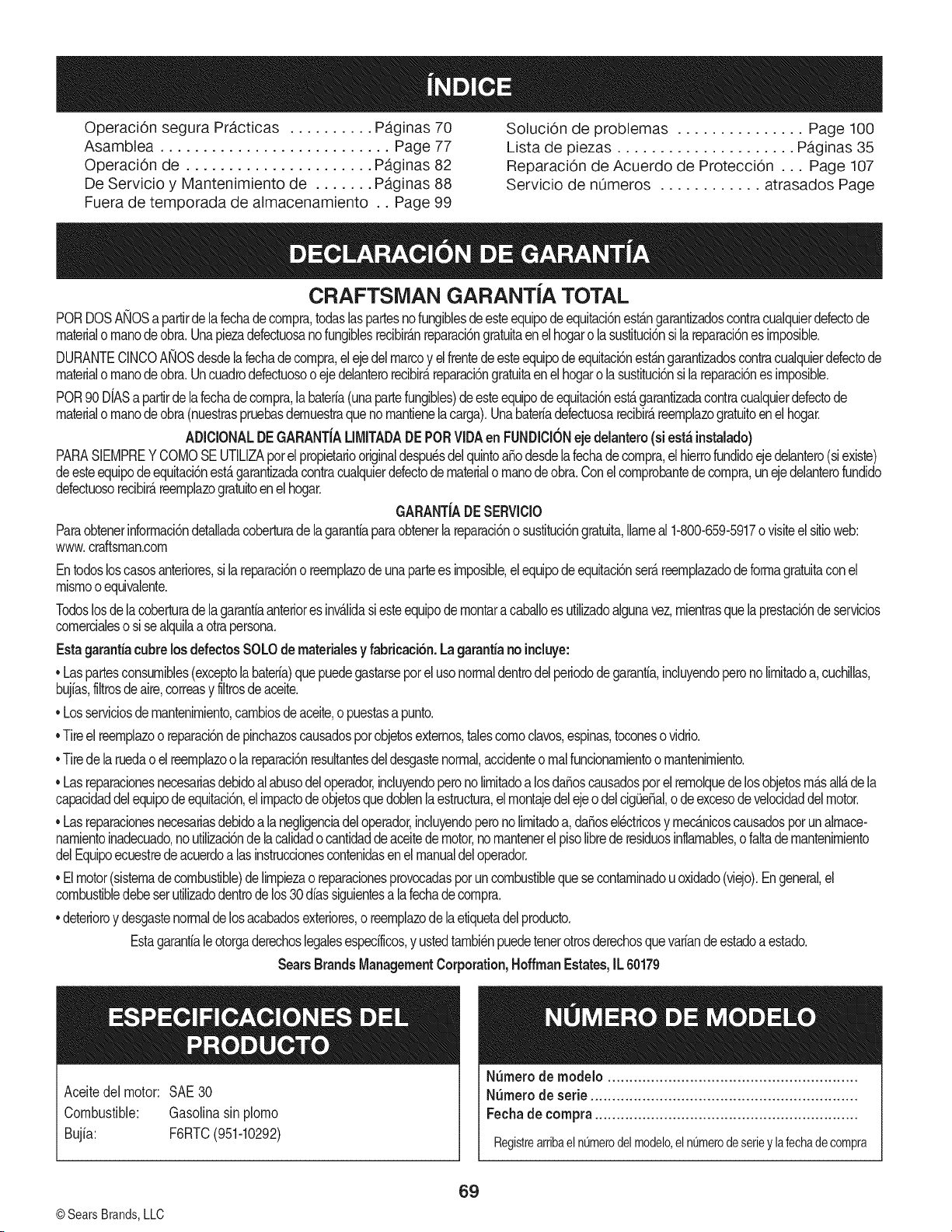
Operaci6n segura Pr,_cticas .......... Paginas 70 Soluci6n de problemas ............... Page 100
Asamblea ........................... Page 77 Lista de piezas ..................... Paginas 35
Operaci6n de ...................... Paginas 82 Reparaci6n de Acuerdo de Protecci6n ... Page 107
De Servicio y Mantenimiento de ....... Paginas 88 Servicio de nOmeros ............ atrasados Page
Fuera de temporada de almacenamiento .. Page 99
CRAFTSMAN GARANTiA TOTAL
PORDOSANOSa partirde lafechadecornpra,todaslaspartesnofungiblesde esteequipodeequitaci6nest_ngarantizadoscontracualquierdefectode
materialo rnanodeobra.Unapiezadefectuosanofungiblesrecibir_.nreparaci6ngratuitaenel hogaro lasustituci6nsi lareparaci6nes irnposible.
DURANTECINCOANOSdesdelafechadecornpra,el ejedel marcoy elfrentedeesteequipodeequitacbnest_ngarantizadoscontracualquierdefectode
materialo rnanodeobra.Uncuadrodefectuosoo ejedelanterorecibir_reparacbngratuitaenelhogarolasustitucbnsila reparacbnesirnposible.
POR90 DIASapartrdela fechadecornpra,labateria(unapartefungibles)de esteequipodeequitaci6nest_garantizadacontracualquierdefectode
materialo rnanodeobra(nuestraspruebasdernuestraquenornantienelacarga).Unabateriadefectuosarecibir_,reernplazogratuitoen el hogar.
ADICIONALDEGARANTiALIMITADADEPORVIDAen FUNDICIONejedelantero(si est;_instalado)
PARASIEMPREYCOMOSEUTILIZAporelpropietariooriginaldespu_sdelquintoa_odesdelafechadecornpra,elhierrofundidoejedelantero(siexiste)
deesteequipodeequitacbnest_garantizadacontracualquierdefectodematerialornanodeobra.Conelcornprobantedecornpra,unejedelanterofundido
defectuosorecibir_reernplazogratuitoenelhogar.
GARANTiADESERVICIO
Paraobtenerinforrnaci6ndetaladacoberturade lagarantaparaobtenerlareparaci6no sustituci6ngratuita,Ilarneal1-800-659-5917o visiteel sitioweb:
www.craftsrnan.corn
Entodosloscasosanteriores,si la reparaci6no reernplazodeunapartees irnposible,elequipodeequitacbnser_.reernplazadodeformagratuitaconel
rnisrnoo equivalente.
Todoslosdela coberturade lagarantaanteriores inv&lidasiesteequipodernontaracabaloesutlizadoalgunavez,rnientrasquelaprestacbnde servicios
cornercialeso sisealqulaaotrapersona.
Estagaranta cubrelos defectosSOLOdernaterialesy fabricacibn.Lagaranta no incluye:
• Laspartesconsurnibles(exceptolabateria)quepuedegastarseporelusonormaldentrodelperiodode garanta,incluyendoperonolrnitadoa,cuchllas,
bujias,fltrosdeaire,correasy fltrosdeaceite.
• Losserviciosdemantenimiento,cambiosdeaceite,o puestasa punto.
• Tireel reernplazoo reparacbndepinchazoscausadospotobjetosexternos,talescornoclavos,espinas,toconeso vidrio.
• Tirede la ruedao elreernplazoo la reparaci6nresutantesdeldesgastenormal,accidenteo rnalfuncionarnientoo rnantenirniento.
• Lasreparacionesnecesariasdebidoalabusodeloperador,incluyendoperonolrnitadoa losdaSoscausadosporelrernolquedelosobjetosrn&sall&dela
capacidaddelequipodeequitaci6n,elirnpactodeobjetosquedoblenlaestructura,elrnontajedelejeodelcigieSal,odeexcesodevelocidaddelmotor.
• Lasreparacionesnecesariasdebidoa lanegligenciadeloperador,incluyendoperono lrnitadoa,daios electricosy rnecanicoscausadosporunalrnace-
narnientoinadecuado,noutlizaci6ndelacalidado cantidaddeaceitedemotor,nornantenerelpisolbre de residuosinlarnables,o faltadernantenirniento
delEquipoecuestredeacuerdoalas instruccionescontenidasenelmanualdeloperador.
• Elmotor(sisternadecombustible)delrnpiezaoreparacionesprovocadasporuncombustiblequesecontarninadouoxidado(viejo).Engeneral,el
combustibledebeserutilizadodentrodelos30diassiguientesa la fechadecornpra.
• deterioroy desgastenormaldelosacabadosexteriores,o reernplazodelaetiquetadelproducto.
Estagarantiale otorgaderechoslegalesespecilcos,y ustedtarnbi_npuedetenerotrosderechosquevariandeestadoa estado.
SearsBrandsManagementCorporation,HoffmanEstates,IL60179
Aceitedel motor: SAE30
Combustible: Gasolinasinplorno
Bujia: F6RTC(951-10292)
N_mero de rnodelo ..........................................................
N_mero de serie ..............................................................
Fechade compra .............................................................
RegistrearribaelnQmerodelmodelo,elnQmerodeserieylafechadecompra
© Sears Brands,LLC
69
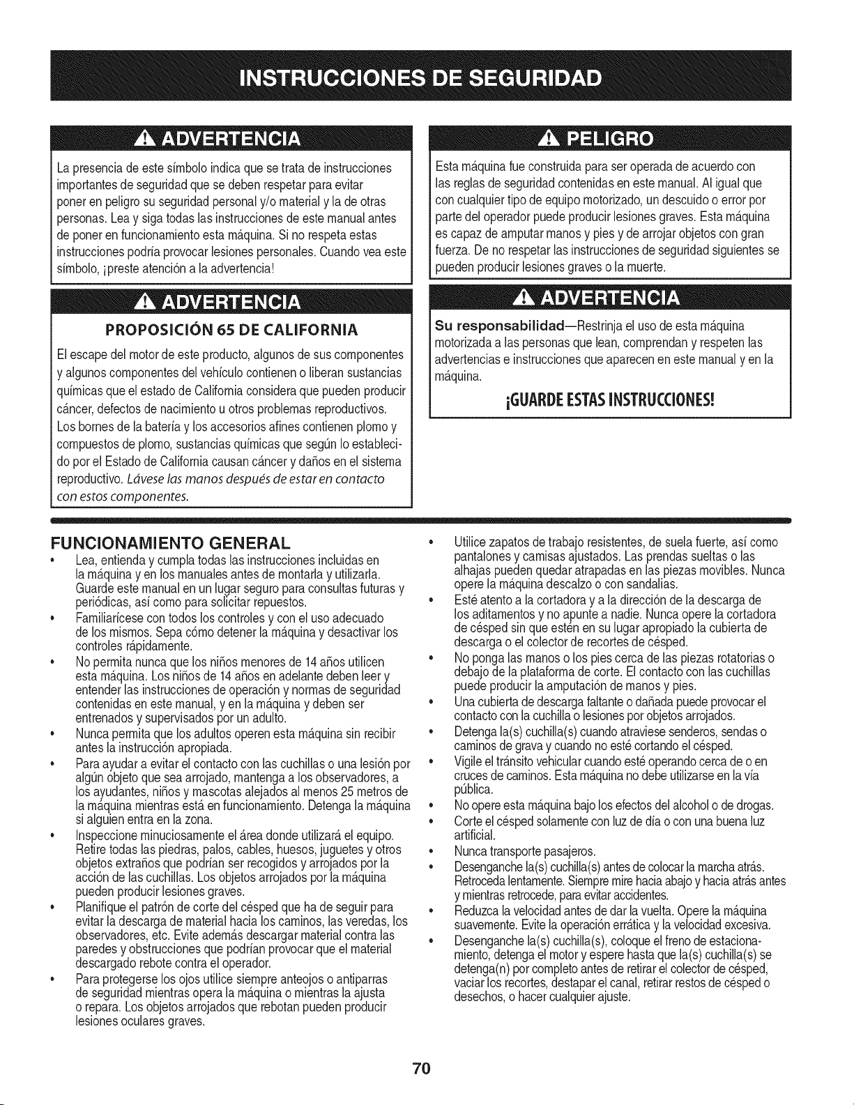
Lapresenciade este sirnboloindicaque setrata de instrucciones
irnportantesde seguridadque se debenrespetarparaevitar
ponerenpeligrosu seguridadpersonaly/o materialy la de otras
personas.Leay sigatodas lasinstruccionesdeeste manualantes
de poneren funcionarnientoestarn_.quina.Si no respetaestas
instruccionespodriaprovocarlesionespersonales.Cuandoveaeste
sirnbolo,ipresteatenci6na la advertencia!
PROPOSICION 65 DE CALIFORNIA
Elescapedel motorde este producto,algunosdesus cornponentes
y algunoscornponentesdelvehiculocontieneno liberansustancias
quirnicasqueel estadode Californiaconsideraque puedenproducir
c_.ncer,defectosde nacirnientou otrosproblernasreproductivos.
Losbornesde la bateriay losaccesoriosdines contienenplornoy
cornpuestosde plorno,sustanciasquirnicasquesegQnIoestableci-
do porel Estadode Californiacausanc_.ncery da_osenel sisterna
reproductivo.Ldveselas manos despu_sde estar en contacto
con estoscomponentes.
Estarn_.quinarueconstruidaparaseroperadade acuerdocon
las reglasde seguridadcontenidasen este manual.AI igualque
concualquiertipo deequipo rnotorizado,undescuidoo error por
partedeloperadorpuedeproducirlesionesgraves.Estarn_.quina
es capazde arnputarrnanosy piesy dearrojarobjetoscon gran
fuerza.De norespetarlas instruccionesde seguridadsiguientesse
puedenproducirlesionesgraveso la rnuerte.
Su responsabilidad--Restrinja el usode esta rn_.quina
rnotorizadaalas personasque lean,cornprendany respetenlas
advertenciase instruccionesqueaparecenen este manualyen la
rn_.quina.
iGUARI)E ESTASINSTRUCCIONES!
FUNCIONAMIENTO GENERAL
• Lea,entienday curnplatodaslas instruccionesincluidasen
la rn_.quinayen los rnanualesantesde rnontarlay utilizarla.
Guardeestemanualen un lugarseguroparaconsultasfuturasy
peri6dicas,asi cornoparasolicitarrepuestos.
• Farniliaricesecontodoslos controlesy con el usoadecuado
de losrnisrnos.Sepa c6rnodetenerlarn_.quinay desactivarlos
controlesr_.pidarnente.
• No perrnitanuncaque losni_os rnenoresde 14a_osutilicen
estarn_.quina.Los ni_osde 14a_osenadelantedebenleery
entenderlas instruccionesde operaci6ny norrnasde seguridad
contenidasen estemanual,yen la rn_.quinay debenser
entrenadosy supervisadospor un adulto.
• Nuncaperrnitaque los adultosoperenestarn_.quinasin recibir
antesla instrucci6napropiada.
• Paraayudara evitarel contactocon las cuchillaso una lesi6npor
algQnobjetoqueseaarrojado,rnantengaa los observadores,a
los ayudantes,ni_osy rnascotasalejadosal rnenos25 metrosde
la rn_.quinarnientrasest,. en funcionarniento.Detengala rn_.quina
si alguienentraen la zona.
• Inspeccionerninuciosarnenteel Areadondeutilizar_,el equipo.
Retiretodaslas piedras,palos,cables,huesos,juguetesy otros
objetosextra_osquepodrianser recogidosy arrojadosporla
acci6nde lascuchillas.Losobjetosarrojadospor la rn_.quina
puedenproducirlesionesgraves.
• Planifiqueel patr6nde corte del c_spedque hadeseguirpara
evitarla descargade materialhacialoscarninos,lasveredas,los
observadores,etc. Eviteadern_.sdescargarmaterialcontralas
paredesy obstruccionesque podrianprovocarqueel material
descargadorebotecontrael operador.
• Paraprotegerselos ojosutilicesiernpreanteojoso antiparras
de seguridadrnientrasoperala rn_.quinao rnientraslaajusta
o repara.Losobjetosarrojadosque rebotanpuedenproducir
lesionesocularesgraves.
• Utilicezapatosde trabajoresistentes,desuelafuerte,asi corno
pantalonesy carnisasajustados.Lasprendassueltaso las
alhajaspuedenquedaratrapadasen las piezasrnovibles.Nunca
operela rn_.quinadescalzoo con sandalias.
• Est_atentoa la cortadoray a la direcci6ndela descargade
los aditarnentosy noapuntea nadie.Nuncaoperela cortadora
de cespedsin que est_nen su lugarapropiadola cubiertade
descargao elcolectorde recortesde c_sped.
• Nopongalas rnanoso los piescercade las piezasrotatoriaso
debajode la plataforrnadecorte. Elcontactocon las cuchillas
puedeproducirla arnputaci6ndernanosy pies.
• Unacubiertadedescargafaltanteoda_adapuedeprovocarel
contactoconla cuchillao lesionespor objetosarrojados.
• Detengala(s)cuchilla(s)cuandoatraviesesenderos,sendaso
carninosdegravay cuandonoest_cortandoel c_sped.
• Vigileeltr_.nsitovehicularcuandoest_operandocercadeoen
crucesde carninos.Estarn_.quinanodebeutilizarseenla via
pQblica.
• Noopereesta rn_.quinabajo losefectosdel alcoholo de drogas.
• Corteel cespedsolarnentecon luzde dia o con unabuenaluz
artificial.
• Nuncatransportepasajeros.
• Desenganchela(s)cuchilla(s)antesdecolocarlarnarchaatr_.s.
Retrocedalentarnente.Siernpremirehaciaabajoy haciaatr_.santes
y rnientrasretrocede,paraevitaraccidentes.
• Reduzcalavelocidadantesdedarlavuelta.Operelarn_.quina
suavernente.Evitela operaci6nerr_.ticay la velocidadexcesiva.
• Desenganchela(s)cuchilla(s),coloqueel frenodeestaciona-
rniento,detengael motory esperehastaquela(s)cuchilla(s)se
detenga(n)porcornpletoantesderetirarel colectorde c_sped,
vaciarlos recortes,destaparel canal,retirarrestosde cespedo
desechos,o hacercualquierajuste.
7O
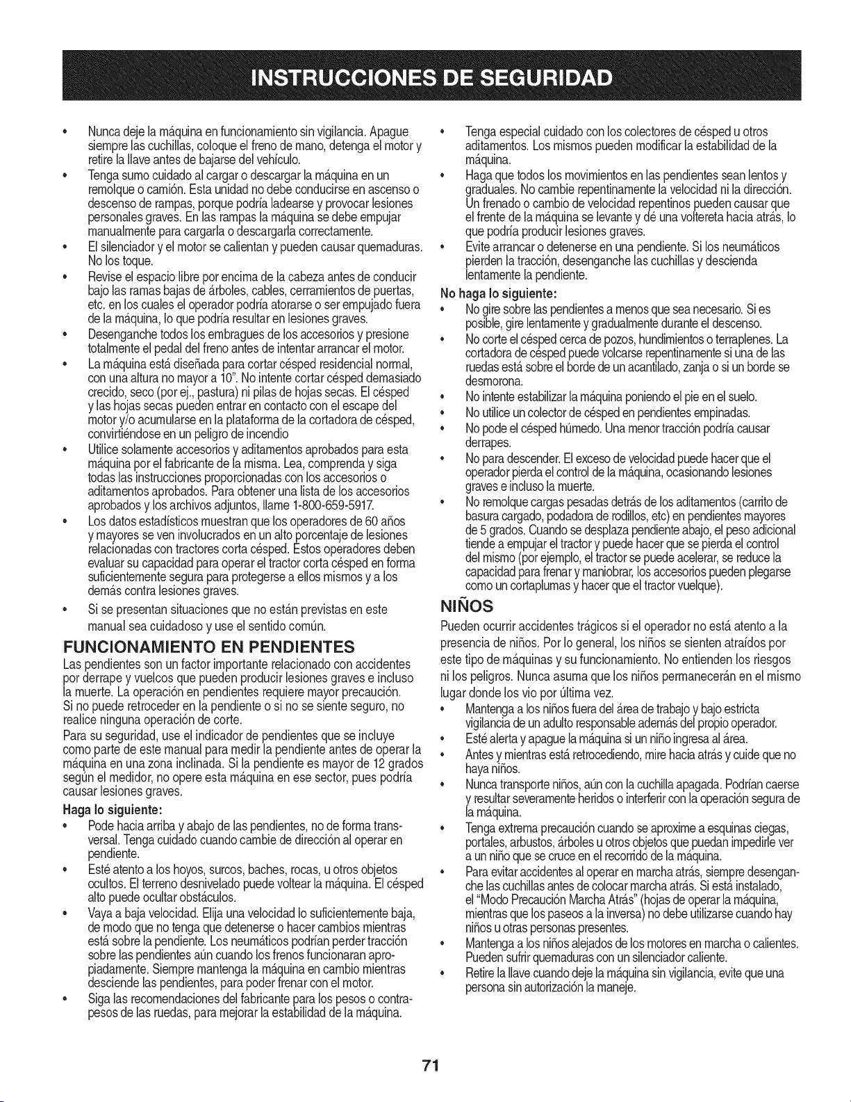
• Nuncadejelarn_.quinaenfuncionarnientosinvigilancia.Apague
siernprelascuchillas,coloqueelfrenode rnano,detengael motory
retirela Ilaveantesdebajarsedel vehiculo.
• Tengasurnocuidadoal cargaro descargarla rn_.quinaen un
rernolqueocarni6n.Estaunidadnodebeconducirseenascensoo
descensoderarnpas,porquepodrialadearsey provocarlesiones
personalesgraves.Enlas rarnpasla rn_.quinasedebe ernpujar
rnanualrnenteparacargarlao descargarlacorrectarnente.
• Elsilenciadory elmotorse calientany puedencausarquernaduras.
No lostoque.
• Reviseel espaciolibreporencirnade lacabezaantesdeconducir
bajolas rarnasbajasde _.rboles,cables,cerrarnientosde puertas,
etc.enloscualesel operadorpodriaatorarseo seternpujadofuera
dela rn_.quina,Ioquepodriaresultarenlesionesgraves.
• Desenganchetodoslosernbraguesde losaccesoriosy presione
totalrnenteel pedaldel frenoantesde intentararrancarel motor.
• Larn_.quinaest,.dise_adaparacortarc_spedresidencialnormal,
conunaalturanomayora 10".Nointentecortarcespeddernasiado
crecido,seco(porej.,pastura)nipilasde hojassecas.El c_sped
y las hojassecaspuedenentrarencontactocon elescapedel
motory/o acurnularseen la plataforrnade lacortadorade cesped,
convirti_ndoseen unpeligrodeincendio
• Utilicesolarnenteaccesoriosy aditarnentosaprobadosparaesta
rn_.quinaporel fabricantedela rnisrna.Lea,cornprenday siga
todaslasinstruccionesproporcionadascon losaccesorioso
aditarnentosaprobados.Paraobtenerunalistadelos accesorios
aprobadosy losarchivosadjuntos,Ilarne1-800-659-5917.
• Losdatosestadfsticosrnuestranquelosoperadoresde60 a_os
y rnayoresseven involucradosenun altoporcentajede lesiones
relacionadascontractorescortacesped.Estosoperadoresdeben
evaluarsu capacidadparaoperareltractorcortac_spedenforrna
suficienternenteseguraparaprotegersea ellosrnisrnosy a los
dern_.scontralesionesgraves.
Si se presentansituacionesqueno est_.nprevistasen este
manualsea cuidadosoy use el sentidocornQn.
FUNCIONAMIENTO EN PENDIENTES
Las pendientesson un factorirnportanterelacionadoconaccidentes
porderrapey vuelcosquepuedenproducirlesionesgravese incluso
la rnuerte.Laoperaci6nen pendientesrequiemmayorprecauci6n.
Si nopuederetrocederen la pendienteo si no se sienteseguro,no
realiceningunaoperaci6ndecorte.
Parasuseguridad,use el indicadorde pendientesquese incluye
cornoparte de este manualpara rnedirla pendienteantesde operarla
rn_.quinaenuna zonainclinada.Si la pendientees mayorde 12grados
segQnelrnedidor,noopereestarn_.quinaenese sector,puespodria
causarlesionesgraves.
HagaIo siguiente:
• Podehaciaarribay abajode laspendientes,node forrnatrans-
versal.Tengacuidadocuandocarnbiededirecci6nal operaren
pendiente.
• Est_atentoa loshoyos,surcos,baches,rocas,uotrosobjetos
ocultos.Elterrenodesniveladopuedevoltearla rn_.quina.El cesped
altopuedeocultarobst_.culos.
• Vayaa bajavelocidad.ElijaunavelocidadIo suficienternentebaja,
dernodoque notengaquedetenerseo hacercarnbiosrnientras
est,.sobrelapendiente.Losneurn_.ticospodrianperdertracci6n
sobrelaspendientesaQncuandolosfrenosfuncionaranapro-
piadarnente.Siernprernantengalarn_.quinaencarnbiornientras
desciendelas pendientes,parapoderfrenarcon el motor.
• Sigalas recornendacionesdelfabricanteparalospesoso contra-
pesosde lasruedas,pararnejorarlaestabilidaddela rn_.quina.
Tengaespecialcuidadocon loscolectoresdec_spedu otros
aditarnentos.Losrnisrnospuedenrnodificarlaestabilidaddela
rn_.quina.
Hagaquetodoslosrnovirnientosenlas pendientesseanlentosy
graduales.No carnbierepentinarnentelavelocidadniladirecci6n.
Unfrenadoo carnbiode velocidadrepentinospuedencausarque
el frentede larn_.quinase levantey d_ unavolteretahaciaatr_.s,Io
quepodriaproducirlesionesgraves.
Evitearrancaro detenerseenunapendiente.Silosneurn_.ticos
pierdenlatracci6n,desenganchelascuchillasy descienda
lentarnentelapendiente.
No hagaIo siguiente:
• Nogiresobrelaspendientesa rnenosqueseanecesario.Sies
posible,girelentarnentey gradualrnenteduranteeldescenso.
• Nocorteel cespedcercadepozos,hundirnientosoterraplenes.La
cortadoradec_spedpuedevolcarserepentinarnentesiunadelas
ruedasest,.sobreel hordedeunacantilado,zanjao siunhordese
desrnorona.
• Nointenteestabilizarlarn_.quinaponiendoelpieenel suelo.
• Noutiliceuncolectordec_spedenpendientesernpinadas.
• Nopodeel cespedhOrnedo.Unarnenortracci6npodriacausar
derrapes.
• Noparadescender.El excesode velocidadpuedehacerqueel
operadorpierdael controldelarn_.quina,ocasionandolesiones
graveseinclusolarnuerte.
• Norernolquecargaspesadasdetr_.sdelosaditarnentos(carritode
basuracargado,podadorade rodillos,etc)en pendientesrnayores
de5 grados.Cuandosedesplazapendienteabajo,elpesoadicional
tiendeaernpujarel tractory puedehacerquesepierdaelcontrol
delrnisrno(potejernplo,eltractorse puedeacelerar,sereducela
capacidadparafrenary rnaniobrar,losaccesoriospuedenplegarse
cornouncortaplurnasy hacerqueeltractorvuelque).
NINOS
Puedenocurriraccidentestr_.gicossi el operadorno est,. atentoa la
presenciade ni_os. PorIo general,los ni_osse sientenatraidospor
estetipo dern_.quinasy su funcionarniento.Noentiendenlos riesgos
nilos peligros.Nuncaasurnaque los ni_osperrnanecer_.nen el rnisrno
lugardondelos vio porQltirnavez.
Mantengaalosni_osfueradel_readetrabajoy bajoestricta
vigilanciadeunadultoresponsableadern_.sdel propiooperador.
Est_alertay apaguelarn_.quinasiunni_oingresaal _.rea.
Antesy rnientrasest,.retrocediendo,mirehaciaatr_.sy cuidequeno
hayani_os.
Nuncatransporteni_os,aQnconlacuchillaapagada.Podriancaerse
y resultarseverarnenteheridoso interferirconlaoperaci6nsegurade
larn_.quina.
Tengaextrernaprecauci6ncuandoseaproxirnea esquinasciegas,
portales,arbustos,_.rbolesuotrosobjetosquepuedanirnpedirlever
a unni_oque secruceen el recorridode la rn_.quina.
Paraevitaraccidentesaloperarenrnarchaatr_.s,siernpredesengan-
chelascuchillasantesdecolocarrnarchaatr_.s.Siest,.instalado,
el"ModoPrecauci6nMarchaAtr_.s"(hojasdeoperarla rn_.quina,
rnientrasquelospaseosa lainversa)nodebeutilizarsecuandohay
ni_osuotraspersonaspresentes.
Mantengaalosni_osalejadosdelosrnotoresenrnarchaocalientes.
Puedensufrirquernadurasconun silenciadorcaliente.
RetirelaIlavecuandodejelarn_.quinasinvigilancia,evitequeuna
personasinautorizaci6nla rnaneje.
71
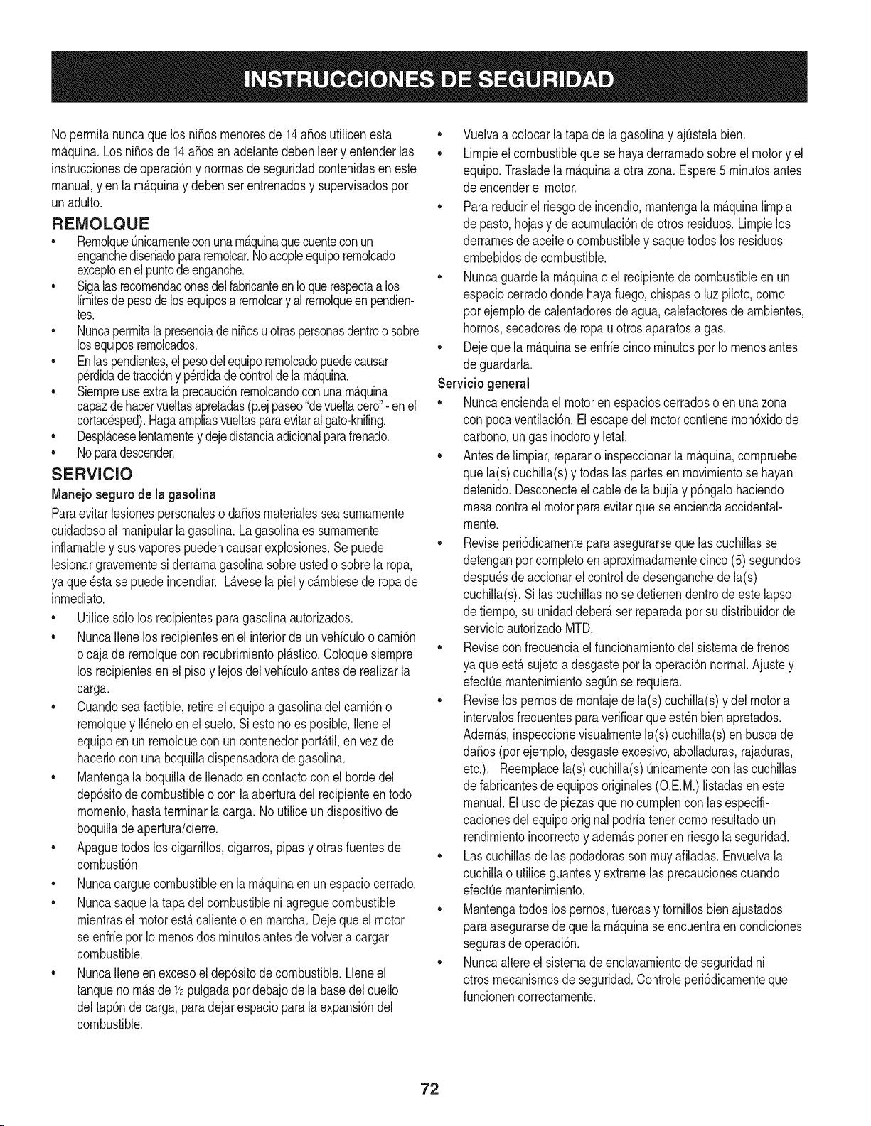
No perrnitanuncaque losniSosrnenoresde 14aSosutilicenesta
rn_.quina.Los niSosde 14aSosen adelantedebenleer y entenderlas
instruccionesdeoperaci6ny norrnasde seguridadcontenidasen este
manual,y enla rn_.quinay deben serentrenadosy supervisadospor
unadulto.
REIVIOLQUE
• Rernolque_nicarnenteconunarn_.quinaquecuenteconun
enganchediseSadopararernolcar.Noacopleequiporernolcado
exceptoenelpuntodeenganche.
• Sigalasrecornendacionesdel fabricanteenIoque respectaalos
lirnitesdepesode losequiposa rernolcary al rernolqueenpendien-
tes.
• NuncaperrnitalapresenciadeniSosu otraspersonasdentroo sobre
losequiposrernolcados.
• Enlaspendientes,elpesodelequiporernolcadopuedecausar
p_rdidadetracci6ny p_rdidadecontroldela rn_.quina.
• Siernpreuseextralaprecauci6nrernolcandoconunarn_.quina
capazdehacervueltasapretadas(p.ejpaseo"devueltacero"-en el
cortac_sped).Hagaarnpliasvueltasparaevitaral gato-knifing.
• Despl_.ceselentarnentey dejedistanciaadicionalparafrenado.
• Noparadescender.
SERVIClO
Manejo seguro de la gasolina
Paraevitarlesionespersonaleso daSosrnaterialessea surnarnente
cuidadosoal rnanipularla gasolina.Lagasolinaes surnarnente
inflarnabley sus vaporespuedencausarexplosiones.Sepuede
lesionargravernentesi derrarnagasolinasobreustedo sobrela ropa,
ya que _sta se puedeincendiar.L_.vesela piely c_.rnbiesede ropade
inrnediato.
• Utilices61olos recipientespara gasolinaautorizados.
• NuncaIlenelos recipientesenel interiorde un vehiculoo carni6n
ocaja de rernolquecon recubrirnientopl_.stico.Coloquesiernpre
los recipientesen el piso y lejosdel vehiculoantesde realizarla
carga.
• Cuandosea factible,retireel equipoa gasolinadelcarni6no
rernolquey II_neloen el suelo.Si esto noes posible,Ileneel
equipoen unrernolqueconun contenedorport_.til,envezde
hacerlocon una boquilladispensadoradegasolina.
• Mantengala boquillade Ilenadoen contactocon elhordedel
dep6sitode combustibleo con la aberturadel recipienteen todo
rnornento,hastaterrninarlacarga. No utiliceundispositivode
boquilladeapertura/cierre.
• Apaguetodoslos cigarrillos,cigarros,pipasy otras fuentesde
cornbusti6n.
• Nuncacarguecombustibleen la rn_.quinaen unespaciocerrado.
• Nuncasaquela tapadelcombustibleni agreguecombustible
rnientrasel motorest,. calienteo en rnarcha.Dejequeel motor
se enfrieporIo rnenosdos rninutosantesdevolvera cargar
combustible.
• NuncaIleneenexcesoel dep6sitodecombustible.Lleneel
tanquenorn_.sde1/2pulgadapordebajode la basedelcuello
deltap6nde carga,paradejarespacioparala expansi6ndel
combustible.
• Vuelvaa colocar la tapade la gasolinay ajQstelabien.
• Lirnpieel combustibleque sehayaderrarnadosobreel motory el
equipo.Trasladelarn_.quinaa otrazona. Espere5 rninutosantes
de encenderel motor.
• Parareducirel riesgode incendio,rnantengala rn_.quinalirnpia
de pasto,hojasy deacurnulaci6nde otrosresiduos.Lirnpielos
derrarnesde aceiteo combustibley saquetodos los residuos
ernbebidosde combustible.
• Nuncaguardela rn_.quinao el recipientedecombustibleen un
espaciocerradodondehayafuego,chispaso luz piloto,corno
por ejernplodecalentadoresde agua,calefactoresde arnbientes,
hornos,secadoresde ropau otrosaparatosagas.
• Dejeque la rn_.quinase enfriecinco rninutosporIo rnenosantes
de guardarla.
Servicio general
• Nuncaenciendael motor en espacioscerradoso en unazona
con pocaventilaci6n.El escapedel motorcontienernon6xidode
carbono,ungas inodoroy letal.
• Antesde lirnpiar,repararo inspeccionarlarn_.quina,cornpruebe
que la(s)cuchilla(s)y todaslas partesen rnovirnientose hayan
detenido.Desconecteelcablede la bujfay p6ngalohaciendo
rnasacontrael motorparaevitarquese enciendaaccidental-
rnente.
• Reviseperi6dicarnenteparaasegurarsequelascuchillasse
detenganporcornpletoenaproxirnadarnentecinco (5) segundos
despu_sdeaccionarel controlde desenganchedela(s)
cuchilla(s).Si lascuchillasno se detienendentrode este lapso
de tiernpo,su unidaddeber_,ser reparadapor sudistribuidorde
servicioautorizadoMTD.
• Reviseconfrecuenciael funcionarnientodel sisternade frenos
ya que est,. sujetoa desgastepor la operaci6nnormal.Ajustey
efectQernantenirnientosegQnse requiera.
• Reviselos pernosde rnontajede la(s) cuchilla(s)y del motora
intervalosfrecuentesparaverificarqueest_nbien apretados.
Adern_.s,inspeccionevisualrnentela(s) cuchilla(s)en buscade
daSos(porejernplo,desgasteexcesivo,abolladuras,rajaduras,
etc.). Reernplacela(s) cuchilla(s)Qnicarnentecon las cuchillas
de fabricantesde equiposoriginales(O.E.M.)listadasen este
manual.Eluso de piezasquenocurnplencon lasespecifi-
cacionesdel equipooriginalpodriatenercornoresultadoun
rendirnientoincorrectoy adern_.sponeren riesgola seguridad.
• Lascuchillasde las podadorasson rnuyafiladas.Envuelvala
cuchillao utiliceguantesy extremelas precaucionescuando
efectQernantenirniento.
• Mantengatodoslos pernos,tuercasy tornillosbienajustados
paraasegurarsede quela rn_.quinase encuentraencondiciones
segurasdeoperaci6n.
• Nuncaaltereel sisternade enclavarnientode seguridadni
otrosmecanisrnosde seguridad.Controleperi6dicarnenteque
funcionencorrectarnente.
72
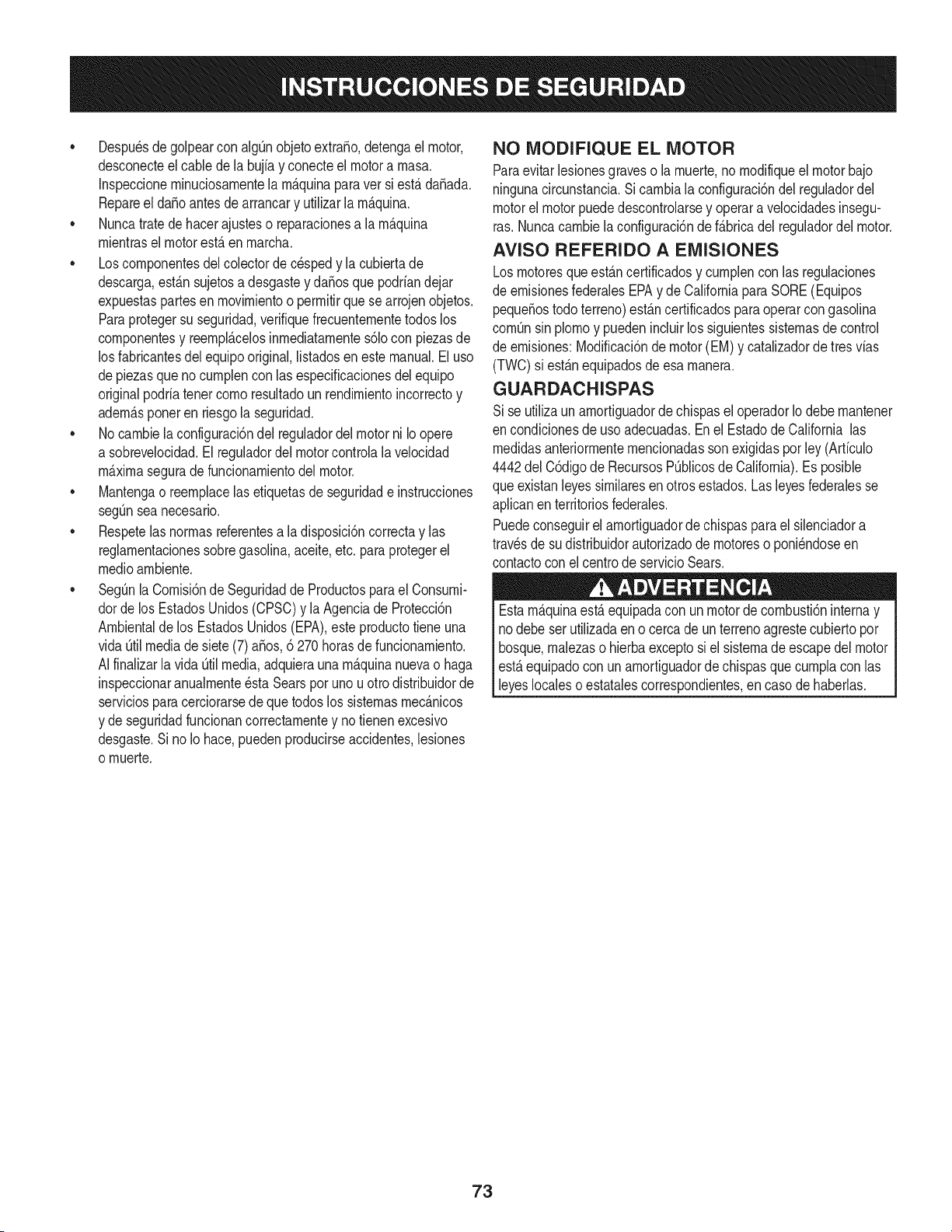
• Despu_sde golpearcon algOnobjetoextrafio,detengael motor,
desconecteelcablede la bujfay conecteel motora rnasa.
Inspeccionerninuciosarnentela rn_.quinaparaver si est,.daSada.
Repareel daSoantesde arrancary utilizarla rn_.quina.
• Nuncatratedehacerajusteso reparacionesa la rn_.quina
rnientrasel motorest,. en rnarcha.
• Loscornponentesdel colectordec_sped y la cubiertade
descarga,est_.nsujetosa desgastey daSosque podriandejar
expuestaspartesen rnovirnientoo perrnitirquesearrojen objetos.
Paraprotegersu seguridad,verifiquefrecuenternentetodos los
cornponentesy reernpl_.celosinrnediatarnentes61ocon piezasde
los fabricantesdel equipooriginal,listadosen este manual.El uso
depiezasque no curnplenconlas especificacionesdel equipo
originalpodriatenercornoresultadoun rendirnientoincorrectoy
adern_.sponeren riesgola seguridad.
• No carnbielaconfiguraci6ndel reguladordel motorni Io opere
a sobrevelocidad.El reguladordel motorcontrolala velocidad
maximaseguradefuncionarnientodel motor.
Mantengao reernplacelasetiquetasde seguridade instrucciones
segOnseanecesario.
Respetelas norrnasreferentesa la disposici6ncorrectay las
reglarnentacionessobregasolina,aceite,etc. paraprotegerel
medicarnbiente.
• SegOnla Cornisi6nde Seguridadde Productosparael Consurni-
dorde los EstadosUnidos(CPSC)y la Agenciade Protecci6n
Arnbientalde los EstadosUnidos(EPA),este productotiene una
vida Qtilmediade siete(7) aSos,6 270 horasde funcionarniento.
AIfinalizarla vida [3tilmedia,adquieraunarn_.quinanuevao haga
inspeccionaranualrnente_sta Searspor uno u otrodistribuidorde
serviciosparacerciorarsedeque todos los sisternasrnec_.nicos
y de seguridadfuncionancorrectarnentey no tienenexcesivo
desgaste.Si no Io hace,puedenproducirseaccidentes,lesiones
o rnuerte.
NO MODIFIQUE EL MOTOR
Paraevitarlesionesgraveso larnuerte,no rnodifiqueel motorbajo
ningunacircunstancia.Si carnbiala configuraci6ndel reguladordel
motorelmotorpuededescontrolarsey operara velocidadesinsegu-
ras.Nuncacarnbielaconfiguraci6ndef_.bricadelreguladordel motor.
AVISO REFERIDO A EMISIONES
Losrnotoresqueest&ncertificadosy curnplencon las regulaciones
de ernisionesfederalesEPAy de CaliforniaparaSORE(Equipos
pequeSostodoterreno)est_.ncertificadosparaoperarcon gasolina
cornOnsinplornoy puedenincluirlossiguientessisternasde control
de ernisiones:Modificaci6ndemotor(EM) y catalizadorde tres vias
(TWO)si est_.nequipadosde esa rnanera.
GUARDACHISPAS
Sise utilizaun arnortiguadordechispasel operadorIo debernantener
en condicionesde usoadecuadas.Enel Estadode Californialas
rnedidasanteriorrnenternencionadassonexigidasporley (Arficulo
4442del C6digode RecursosPOblicosde California).Es posible
queexistanleyessirnilaresenotros estados.Lasleyesfederalesse
aplicanenterritoriosfederales.
Puedeconseguirelarnortiguadorde chispasparael silenciadora
travesde sudistribuidorautorizadode rnotoreso poni_ndoseen
contactocon el centrode servicioSears.
Estarn_.quinaest,.equipadacon un motorde cornbusti6ninternay
nodebe serutilizadaeno cercade un terrenoagrestecubiertopor
bosque,rnalezaso hierbaexceptosi el sisternade escapedel motor
est,.equipadocon un arnortiguadordechispasque curnplacon las
leyeslocalesoestatalescorrespondientes,encasode haberlas.
73

SJlVIBOLOSDE SEGURIDAD
Estap&ginarepresentay describelaseguridadlos simbolosque puedenpareceren este producto.Lea,comprenda,y sigatodasinstrucciones
en lam_quinaantesprocurarparareuniry operar.
i
i
J
0-,
"/5
_J
0
®
LEA EL MANUAL(S) DEL OPERADOR
leido, entienda, y siga todas las instrucciones en el manual(s) antes de procurar montar y funcionar
PELIGRO-- DIe EL CORTE DE PIE
Nunca transporte pasajeros. Nunca transporte niffos, aun con la cuchilla apagada.
PELIGRO-- DIeELCORTEDEPIE
Paraevitar accidentes, mantener a los niffos lejos de la m_iquina mientras est,1en funcionamiento..
PELIGRO-- DIe EL CORTE DE PIE
Guarde manos y pies lejos de hacer girar partes.
PELIGRO-- DIe EL CORTE DE PIE
Retroceda lentamente. Siempre mire hacia abajo y hacia atr_is antes y mientras retrocede, para evitar
accidentes.
PELIGRO-- ESCOMBROS LANZADOS
Quite objetos que pueden set lanzados por la I_imina en cualquier direcci6n. Lleve gafas de
seguridad..
PELIGRO-- ESCOMBROS LANZADOS
Quite objetos que pueden set lanzados pot la I_imina en cualquier direcci6n. Lleve gafas de
seguridad.
ERSONAS PRESENTES
Guarde a las personas presentes, a los ayudantes y a niffos pot Io menos 75 pies lejos.
PELIGRO-- CUESTAS
Use extra la precauci6n en cuestas. No siegue cuestas mayores que 12.
ADVERTENCIA -- SUPERFICIE CALIENTE
Las partes del motor, especialmente el silenciador, Ilega a set muy caliente durante la operaci6n.
Permita motor y silenciador para ponerse frio antes de tocar.
74
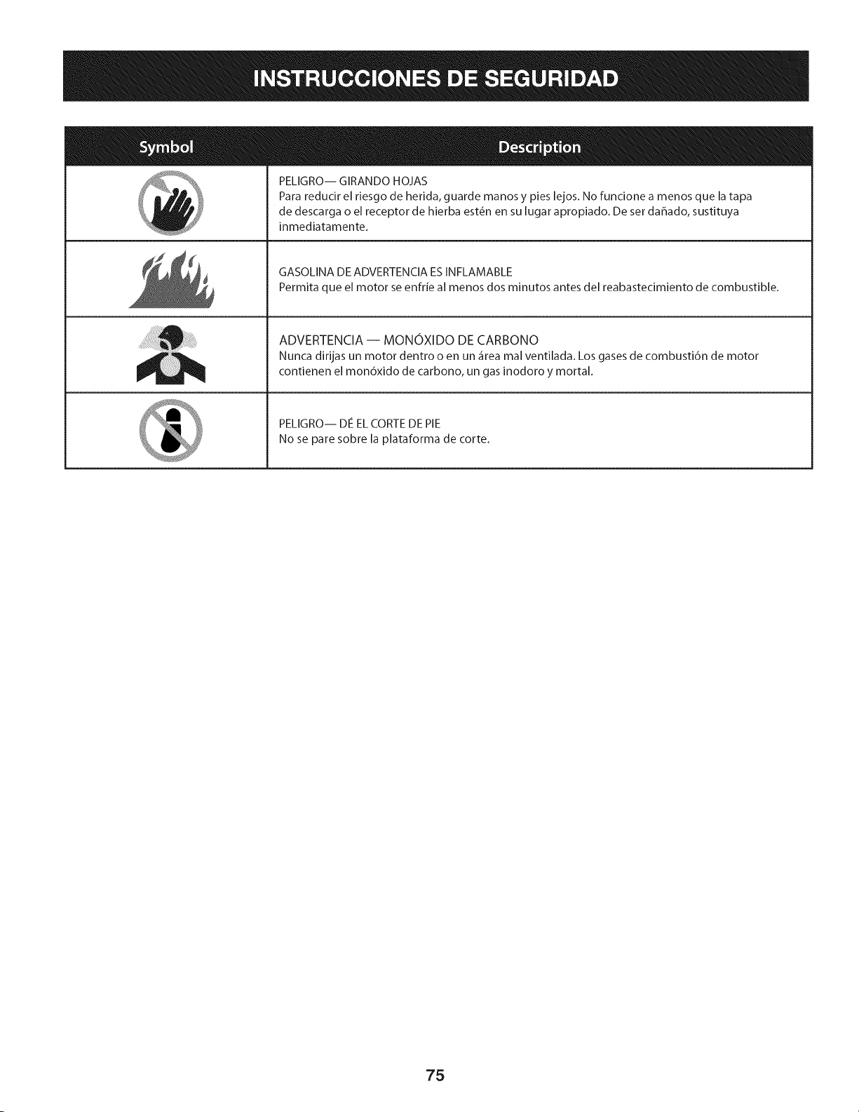
PELIGRO-- GIRANDO HOJAS
Para reducir el riesgo de herida, guarde manos y pies lejos. No funcione a menos que la tapa
de descarga o el receptor de hierba est6n en su lugar apropiado. De ser dahado, sustituya
inmediatamente.
GASOLINA DEADVERTENCIAESINFLAMABLE
Permita que el motor se enfrfe al menos dos minutos antes del reabastecimiento de combustible.
ADVERTENCIA -- MONOXIDO DE CARBONO
Nunca dirijas un motor dentro o en un _rea mal ventilada. Los gases de combusti6n de motor
contienen el mon6xido de carbono, un gas inodoro y mortal.
PELIGRO-- Die EL CORTE DE PIE
No se pare sobre la plataforma de corte.
75
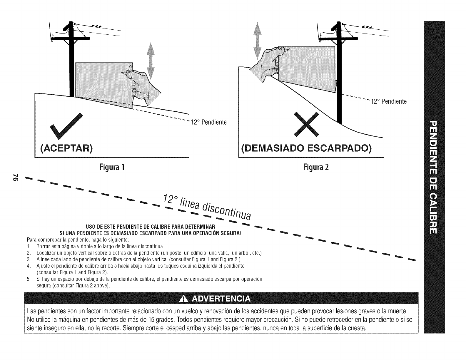
(ACEPTAR)
- 12° Pendiente
-- 12° Pendiente
(DEMASIADO ESCARPADO)
Figura1 Figura2
" " "- 12°/fne,
USODE ESTEPENDIENTEDE CALIBRE PARA DETERMINAR
SI UNA PENDIENTEES DEiVIASIADOESCARPADOPARAUNA OPERACIONSEGURA!
Para comprobar la pendiente, haga Io siguiente:
1. Borrar esta p_gina y doble a Io largo de la linea discontinua.
2.
3.
4.
5,
Localizar un objeto vertical sobre o detr_.sde la pendiente (un poste, un edificio, una valla, un _.rbol,etc.)
Alinee cada lado de pendiente de calibre con el objeto vertical (consultar Figura 1 and Figura 2 ).
Ajuste el pendiente de calibre arriba o hacia abajo hasta los toques esquina izquierda el pendiente
(consultar Figura 1 and Figura 2).
Si hay un espacio pot debajo de la pendiente de calibre, el pendiente es demasiado escarpa pot operaci6n
segura (consultar Figura 2 above).
Las pendientes son un factor importante relacionado con un vuelco y renovaci6nde los accidentes que pueden provocar lesiones graves o la muerte.
No utilice la ma.quinaen pendientesde ma.sde 15 grados. Todospendientes requiere mayor precauci6n. Si no puede retroceder en la pendiente o si se
siente inseguro en ella, no la recorte. Siemprecorte el cesped arriba y abajo las pendientes, nunca en toda la superficie de la cuesta.
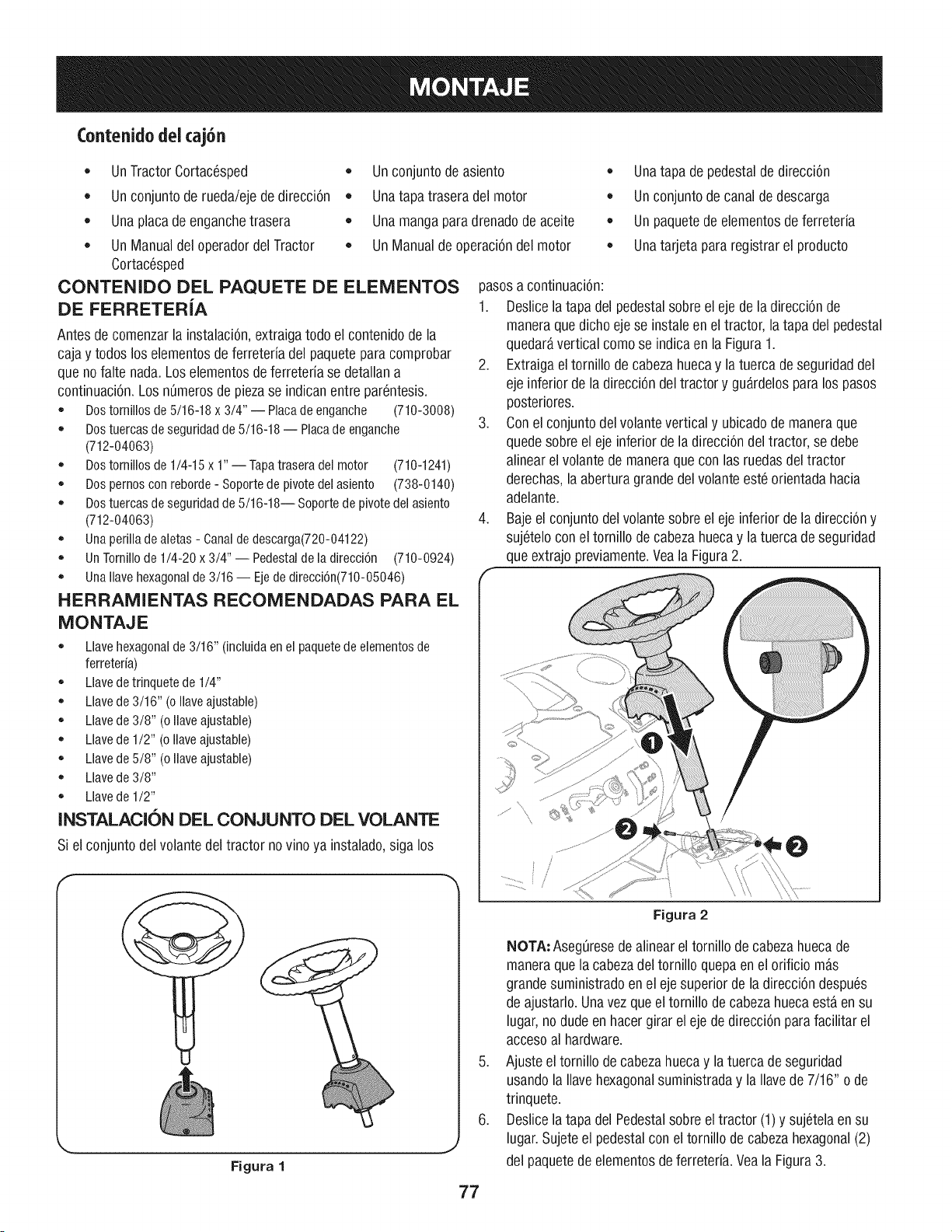
(ontenidodeicaj6n
• UnTractorCortac6sped •
• Unconjuntode rueda/ejede direcci6n
Unaplacade enganchetrasera
• UnManualdeloperadordel Tractor •
Cortac6sped
OONTENIDO DEL PAQUETE DE ELEMENTOS
DE FERRETERiA
Antesde comenzarla instalaci6n,extraigatodo el contenidode la
cajay todosloselementosdeferreteriadel paqueteparacomprobar
queno falte nada.Los elementosde ferreteria se detallana
continuaci6n.Los n0merosdepiezase indicanentre par6ntesis.
• Dostomillosde5/16-18x 3/4" -- Placadeenganche (710-3008)
Dostuercasdeseguridadde5/16-18-- Placadeenganche
(712-04063)
• Dostomillosde1/4-15x 1"-- Tapatraseradel motor (710-1241)
Dospemosconreborde- Soportedepivotedelasiento (738-0140)
Dostuercasdeseguridadde5/16-18-- Soportedepivotedelasiento
(712-04063)
Unaperilladealetas- Canaldedescarga(720-04122)
UnTornillode1/4-20x 3/4" -- Pedestaldeladirecci6n (710-0924)
UnaNavehexagonalde3/16-- Ejede direcci6n(710-05046)
HERRAMIENTAS RECOMENDADAS PARA EL
MONTAJE
Llavehexagonalde3/16" (incluidaenel paquetedeelementosde
ferreteria)
Llavedetrinquetede1/4"
Llavede3/16" (oNaveajustable)
Llavede3/8" (oNaveajustable)
Llavede1/2" (oNaveajustable)
Llavede5/8" (oNaveajustable)
Llavede3/8"
Llavede1/2"
INSTALACI6N DEL CONJUNTO DEL VOLANTE
Si elconjuntodelvolante del tractor novino ya instalado,siga los
Unconjuntodeasiento
Unatapa trasera del motor
Unamangaparadrenadodeaceite
UnManualde operaci6ndel motor
• Unatapa de pedestalde direcci6n
Unconjuntodecanal dedescarga
Unpaquetedeelementosdeferreteria
Unatarjeta pararegistrarel producto
pasosa continuaci6n:
1. Deslicela tapa del pedestalsobreel ejedela direcci6nde
maneraquedichoejese instaleen el tractor, la tapa del pedestal
quedaravertical comose indicaenla Figura1.
2. Extraigaeltornillo decabezahuecay la tuerca de seguridaddel
eje inferiorde la direcci6ndeltractory gu_rdelosparalos pasos
posteriores.
3. Conel conjuntodelvolantevertical y ubicadode maneraque
quedesobre el eje inferiorde la direcci6ndel tractor, se debe
alinearel volante de maneraquecon las ruedasdel tractor
derechas,laaberturagrandedel volante est6 orientadahacia
adelante.
4. Bajeel conjuntodel volantesobre el ejeinferiorde ladirecci6ny
suj6teloconel tornillo de cabezahuecay la tuerca de seguridad
queextrajo previamente.VealaFigura2.
Figura 1
,J
.
.
Figura 2
NOTA: Aseg0resedealineareltornillo de cabezahuecade
maneraquela cabezadel tornillo quepaen el orificio mas
grandesuministradoen el ejesuperiorde la direcci6ndespu6s
de ajustarlo.Unavezqueeltornillo de cabezahuecaesta en su
lugar,nodudeenhacergirar el eje de direcci6npara facilitar el
accesoal hardware.
Ajusteel tornillo de cabezahuecay latuercadeseguridad
usandola Ilavehexagonalsuministraday la Ilavede 7/16" o de
trinquete.
Deslicelatapa del Pedestalsobreel tractor (1)y suj6telaen su
lugar.Sujeteel pedestalcon eltornillo decabezahexagonal(2)
del paquetede elementosdeferreteria.VealaFigura3.
77
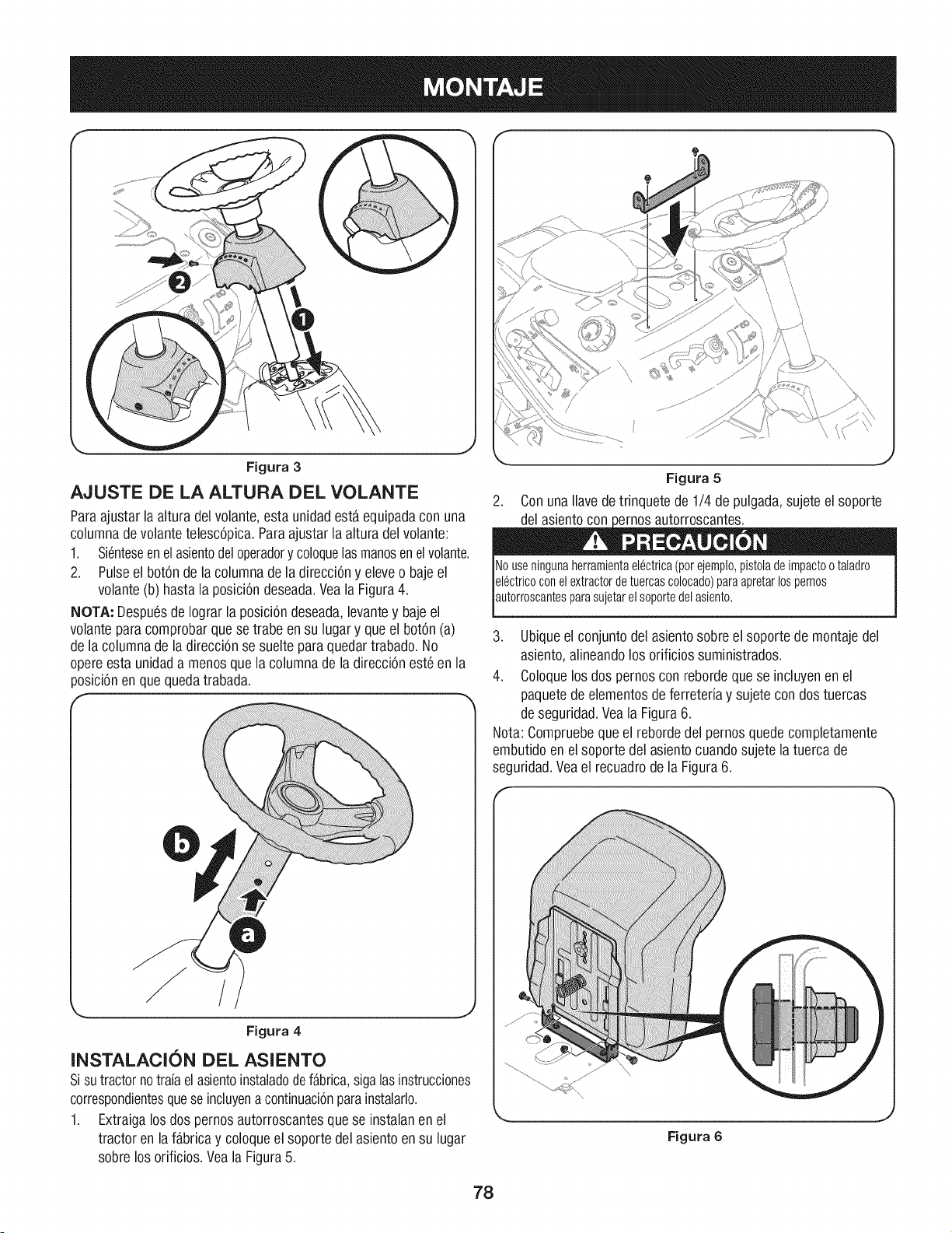
Figura 3
AJUSTE DE LA ALTURA DEL VOLANTE
Paraajustarla altura delvolante,esta unidadestaequipadacon una
columnadevolantetelesc6pica.Paraajustar la altura delvolante:
1. Si6nteseenel asientodeloperadory coloquelasmanosenelvolante.
2. Pulseel bot6ndela columnade la direcci6ny eleveo bajeel
volante(b) hastala posici6ndeseada.Veala Figura4.
NOTA: DespuesdeIograrla posici6ndeseada,levantey bajeel
volanteparacomprobarquese trabe en su lugary que el bot6n(a)
dela columnade la direcci6nse suelteparaquedartrabado.No
o)ereesta unidada menosque la columnade la direcci6nest6 en la
)osici6nen que quedatrabada.
/
Figura 4
INSTALACI6N DEL ASIENTO
Sisutractornotraiaelasientoinstaladodefabrica,sigalasinstrucciones
correspondientesquese incluyena continuaci6nparainstaiarlo.
1. Extraigalos dos pernosautorroscantesque se instalanenel
tractor en la fabrica y coloqueel soportedel asientoensu lugar
sobrelos orificios.Veala Figura5.
J
Figura 5
2. ConunaNavedetrinquetede 1/4 depulgada,sujeteel soporte
Nouseningunaherramientael6ctrica(porejemplo,pistoladeimpactootaladro
el6ctricoconelextractordetuercascolocado)paraapretarlospernos
autorroscantesparasujetare soportedeasento.
3. Ubiqueel conjuntodel asientosobreel soportede montajedel
asiento,alineandolos orificiossuministrados.
4. Coloquelos dos pernoscon rebordequese incluyenenel
paquetedeelementosde ferreteriay sujete con dostuercas
deseguridad.Veala Figura6.
Nota:Compruebequeel rebordedel pernosquedecompletamente
embutidoenel soporte del asientocuandosujete la tuerca de
seguridad.Veael recuadrodela Figura6.
Figura 6
78

AJUSTE DEL ASIENTO
1. Paraajustar la posici6ndel asiento,aflojelas dos perillasde
ajusteque estan ubicadasen la parteinferior delasiento.Deslice
el asientohaciaadelanteo haciaatras,segOnIodesee.Vuelvaa
apretarla perilladeajuste.Consultela Fig. 7.
COLOQUE LA TAPA TRASERA DEL MOTOR
1. Coloqueiatapa traseradel motor ubicandolaen su lugar como
se indicaenla Figura9. Inclinelatapa del motor haciaadelante
paraquecalce dentrodelas ranurasprovistas,luegor6tela
haciaatrasparaalinearlos orificios demontaje.
2. Sujetela tapa con los dostornillos quese incluyenen el paquete
de elementosde ferreteria.Noajustedemasiado.
Figura7
INSTALACION DEL CANAL DE LA PLATAFORMA
NUNCAopereestetractor si notiene colocadosel tap6n deabonoo
el canal de la plataforma.
1. Extraigala perilla de aletas que instal6enla plataformade corte
y conservelapara colocarlaposteriormente.
2. Coloqueel conjuntodel canaldela plataformainsertandolos
dos pasadoresde la basedel canal dela plataformadentro de
los orificiosdetraba de la plataformade la cortadorade c6sped.
Deslicela clavijadeabonohaciaatrasparatrabarla en su lugar,
Asegurandosede activarel interruptorde seguridad.
3. Vuelvaa colocar la perillade aletasy aprietemanualmentepara
sujetarla.Veala Figura8.
Figura9
Instalaci6n de la placa de enganche
1. Ubiquela placade enganchecon el ladopianohaciaarriba,
comose indica enla Fig.10. Suj6telacon los dospernosy las
tuercashexagonalesquese incluyenenel paquetede elementos
deferreted&
Figura10
Figura8 79
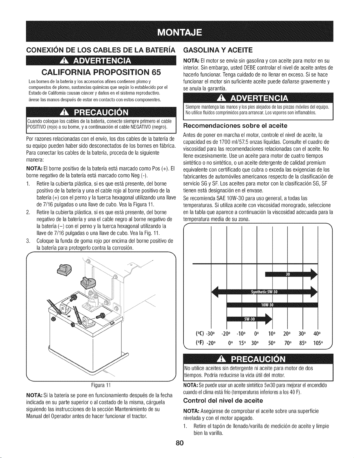
CONEXI6N DE LOS CABLES DE LA BATER|A
CALIFORNIA PROPOSiTiON 65
Los bornes de la bateria y los accesorios afines contienen plomo y
compuestos de plomo, sustancias qufmicas que seg_n Io establecido por el
Estado de California causan cancer y dafios en el sistema reproductivo.
avese las manos despu_s de estar en contacto con estos componentes.
Cuandocoloqueloscables de la bateria, conectesiempreprimero elcable
Posmvo (rojo) a su borne, y a continuaci6nelcable NEGATIVO(negro).
Porrazonesrelacionadascon el envio,losdos cablesde la bateriade
su equipo puedenhabersido desconectadosde los bornesen fabric&
Paraconectarlos cablesde la bateria,procedade la siguiente
manera:
NOTA: Elbornepositivodela bateriaesta marcadocomo Pos(+). El
bornenegativode la bateriaesta marcadocomo Neg(-).
1. Retirela cubierta plastica,si es queesta presente,del borne
positivodela bateriay una el cablerojoal borne positivodela
bateria(+) con el pernoy latuerca hexagonalutilizandounaIlave
de7/16 pulgadaso una Ilavede cubo.Vea la Figura11.
2. Retirela cubierta plastica,si es queesta presente,del borne
negativodela bateriay una el cable negroal bornenegativode
la bateria(-) con el pernoy latuerca hexagonalutilizandola
Ilavede 7/16 pulgadaso una Ilavede cubo.Veala Fig.11.
3. Coloquela funda degomarojo porencimadel bornepositivode
la bateriaparaprotegerlocontrala corrosi6n.
\ J
Figura11
NOTA: Si la bateriase pone en funcionamientodespu6sde la fecha
indicadaen su parte superioroal costadode la misma, carguela
siguiendolas instruccionesde la secci6nMantenimientode su
ManualdelOperadorantesde hacerfuncionarel tractor.
GASOUNA Y ACEITE
NOTA: Elmotor se enviasin gasolinay conaceite paramotorensu
interior.Sinembargo,usted DEBEcontrolarel nivelde aceite antesde
hacerlofuncionar.Tengacuidadode noIlenarenexceso.Si se hace
funcionarel motorsin suficienteaceitepuededa_arsegravementey
se anula la garantia.
Siempremantengalasmanosy los piesalejadosdelaspiezasm6vilesdelequipo.
Noutilicefluidoscomprimidosparaarrancar.Losvaporessoninflamables.
Recomendaciones sobre ei aceite
Antesde poneren marcha el motor,controleel nivelde aceite,la
capacidades de1700 ml/57.5 onzasliquidas.Consulteel cuadrode
viscosidadparalas recomendacionesrelacionadasconel aceite.No
Ileneexcesivamente.Useun aceitepara motordecuatrotiempos
sint6ticoo no sint6tico,o un aceitedetergentedecalidadpremium
equivalentecon certificadoquecubrao excedalas exigenciasde los
fabricantesde autom6vilesamericanosrespectode la clasificaci6nde
servicio SGy SE Losaceitesparamotor con laclasificaci6nSG,SF
tienen esta designaci6nen el envase.
SerecomiendaSAE10W-30para uso general,atodas las
temperaturas.Si utilizaaceiteconviscosidadmonogrado,seleccione
enla tabla queaparecea continuaci6nla viscosidadadecuadapara la
temperaturamediade su zona.
--ram
m
remit,
-20o -10o 0o 100
0o 150 30o 50o
(°C) -30o 200 300 400
(oF) -200 700 850 1050
Noutilice aceitessin detergenteni aceiteparamotorde dos
tiempos.Podriareducirsela vida 0til delmotor.
NOTA:Sepuedeusarunaceitesint6tico5w30paramejorarel encendido
cuandoelclimaestafrio(temperaturasinferioresalos40 F).
Control del nivei de aceite
NOTA: Aseg0resede comprobarel aceitesobre unasuperficie
niveladay con el motor apagado.
1. Retireel tapOnde Ilenado/varillade mediciOnde aceitey limpie
bienla varilla.
8O
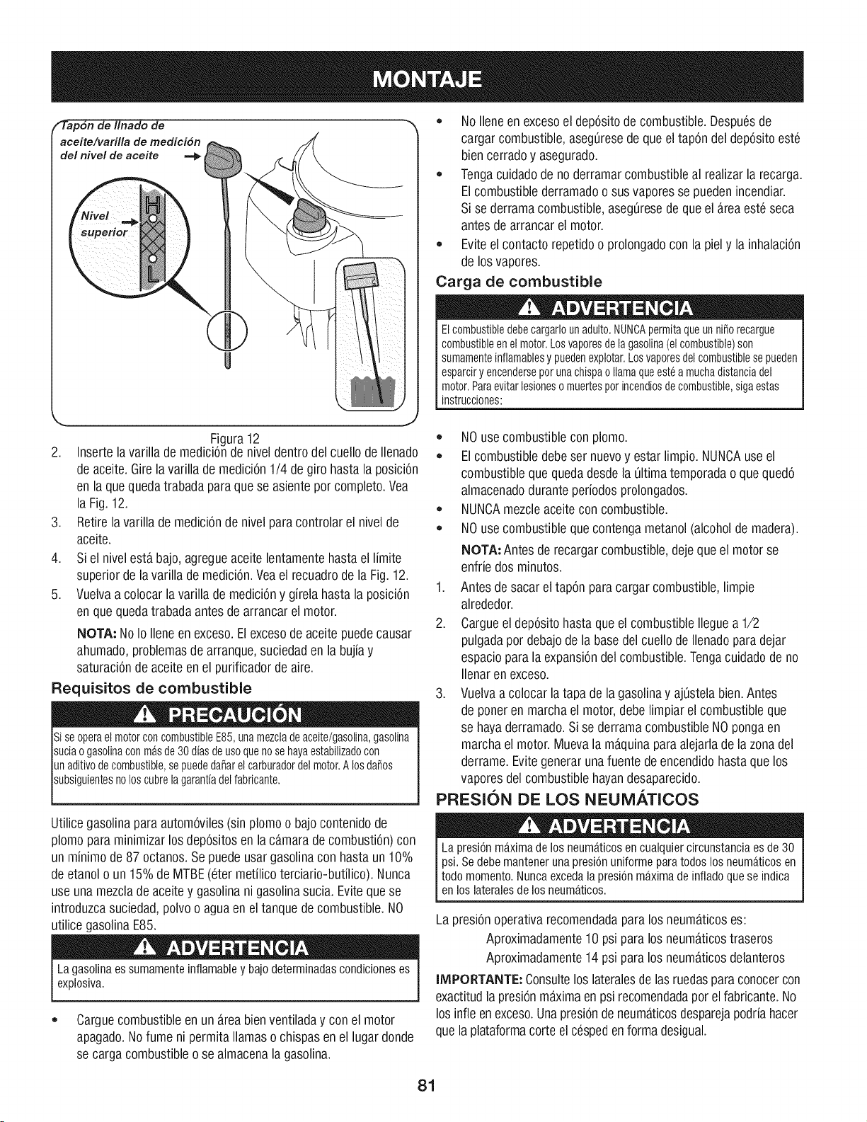
_'ap6n de Ilnado de
aceite/varilla de medici6n
del nivel de aceite .=_
J
Figura12
2. Insertelavarilla de medici6nde niveldentro del cuellode Ilenado
de aceite.Girela varilla demedici6n1/4 degiro hastala posici6n
en laquequedatrabadaparaque se asienteporcompleto.Vea
la Fig.12.
3. Retirela varillade medici6ndenivel paracontrolarel nivelde
aceite.
4. Si el nivel estabajo,agregueaceitelentamentehastaei limite
superiordelavarilla de medici6n.Veael recuadrode la Fig. 12.
5. Vuelvaa colocar la varilla de medici6ny girela hasta la posici6n
en quequedatrabadaantes de arrancarel motor.
NOTA: No Io Ileneenexceso.Elexcesode aceitepuedecausar
ahumado,problemasde arranque,suciedaden la bujiay
saturaci6nde aceiteen el purificadordeaire.
Requisitos de combustible
siseoperael motorconcombustibleE85,unamezcladeaceite/gasolina,gasolina
suciaogasolinaconmasde30dfasdeusoquenosehayaestabilizadocon
unaditivodecombustible,sepuededafiarelcarburadordelmotor.Alosdafios
subsiguientesnoloscubrelagarantfadelfabricante.
Utilicegasolinaparaautom6viles(sin plomoo bajocontenidode
plomoparaminimizarlos dep6sitosenla camarade combusti6n)con
un minimode 87 octanos.Sepuedeusar gasolinacon hasta un 10%
de etanolo un15%de MTBE(6ter metilicoterciario-butilico).Nunca
use una mezclade aceitey gasolinani gasolinasucia.Evitequese
introduzcasuciedad,polvoo aguaen eltanquede combustible.NO
utilicegasolinaE85.
La gasolina essumamenteinflamabley bajodeterminadascondicioneses
explosiva.
• Carguecombustibleen unareabienventiladay con el motor
apagado.Nofume ni permita llamas o chispasen el lugar donde
se cargacombustibleose almacenalagasolina.
NoIleneen excesoel dep6sitode combustible.Despu6sde
cargar combustible,aseg0resede queeltap6n del dep6sitoest6
biencerradoy asegurado.
Tengacuidadode noderramarcombustibleal realizarla recarga.
Elcombustiblederramadoosus vaporesse puedenincendiar.
Si se derramacombustible,aseg0resedequeel areaest6seca
antesde arrancarelmotor.
• Eviteelcontactorepetidoo prolongadocon la piel y la inhalaci6n
de losvapores.
Carga de combustible
Elcombustibledebecargarlounadulto.NUNCApermitaqueunniSorecargue
combustibleenelmotor.Losvaporesdelagasolina(elcombustible)son
sumamenteinflamablesy puedenexplotar.Losvaporesdelcombustiblesepueden
esparciryencenderseporunachispaollamaqueest6amuchadistanciadel
motor.Paraevitarlesionesomuertespotincendiosdecombustible,sigaestas
instrucciones:
• NOuse combustiblecon plomo.
• Elcombustibledebeser nuevoy estar limpio.NUNCAuse el
combustiblequequedadesdela 01timatemporadao que qued6
almacenadoduranteperiodosprolongados.
NUNCAmezcleaceitecon combustible.
• NOuse combustiblequecontengametanol(alcoholde madera).
NOTA: Antes de recargarcombustible,deje que el motor se
enfrie dos minutos.
1. Antesdesacareltap6n paracargar combustible,limpie
alrededor.
2. Cargueel dep6sitohasta que el combustibleIleguea 1/2
pulgadapor debajode la basedel cuellodeIlenadoparadejar
espacioparala expansi6ndelcombustible.Tengacuidadode no
Ilenaren exceso.
3. Vuelvaa colocar la tapa dela gasolinay aj0stelabien.Antes
de poneren marchael motor,debelimpiarel combustibleque
se hayaderramado.Si se derramacombustibleNOpongaen
marchael motor.Muevala maquinaparaalejarladela zonadel
derrame.Evitegenerarunafuente de encendidohastaque los
vaporesdel combustiblehayandesaparecido.
PRESION DE LOS NEUMATICOS
La presi6nmaxima de los neum_.ticosen cualquiercircunstancia esde 30
psi. Sedebe mantener unapresi6nuniformepara todos los neumaticosen
todo momento.Nuncaexcedala presi6nmaxima de inflado quese indica
en los lateralesde los neumaticos.
Lapresi6noperativarecomendadaparalos neumaticoses:
Aproximadamente10 psi paralos neumaticostraseros
Aproximadamente14 psi paralos neumaticosdelanteros
IMPORTANTE: Consultelos lateralesdelas ruedasparaconocercon
exactitudla presi6nmaximaenpsi recomendadaporel fabricante.No
losinfie enexceso.Unapresi6nde neumaticosdesparejapodriahacer
que laplataformacorte elc6spedenformadesigual.
81
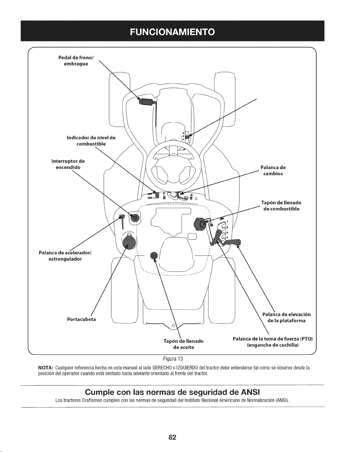
f
Pedal de freno/
embrague
Indicador de nivel de
combustible
Interruptor de
encendido Palanca de
cambios
Palanca r/
estrangulador
Portacubeta
de la plataforma
Tap6n de llenado
de aceite
Figura13
Palanca de la toma de fuerza (PTO)
(enganche de cuchilla)
J
NOTA: Cualquierreferenciahecha en este manualal lado DERECHOo IZQUIERDOdel tractor debeentendersetal comose observadesdela
posici6ndel operador cuandoesta sentadohaciaadelanteorientadoal frente del tractor.
Cumple con las normas de seguridad de ANSI
Los tractoresCrattsmancumplencon las normasde seguridaddel Instituto NacionalAmericanode Normaiizaci6n(ANSi).
82
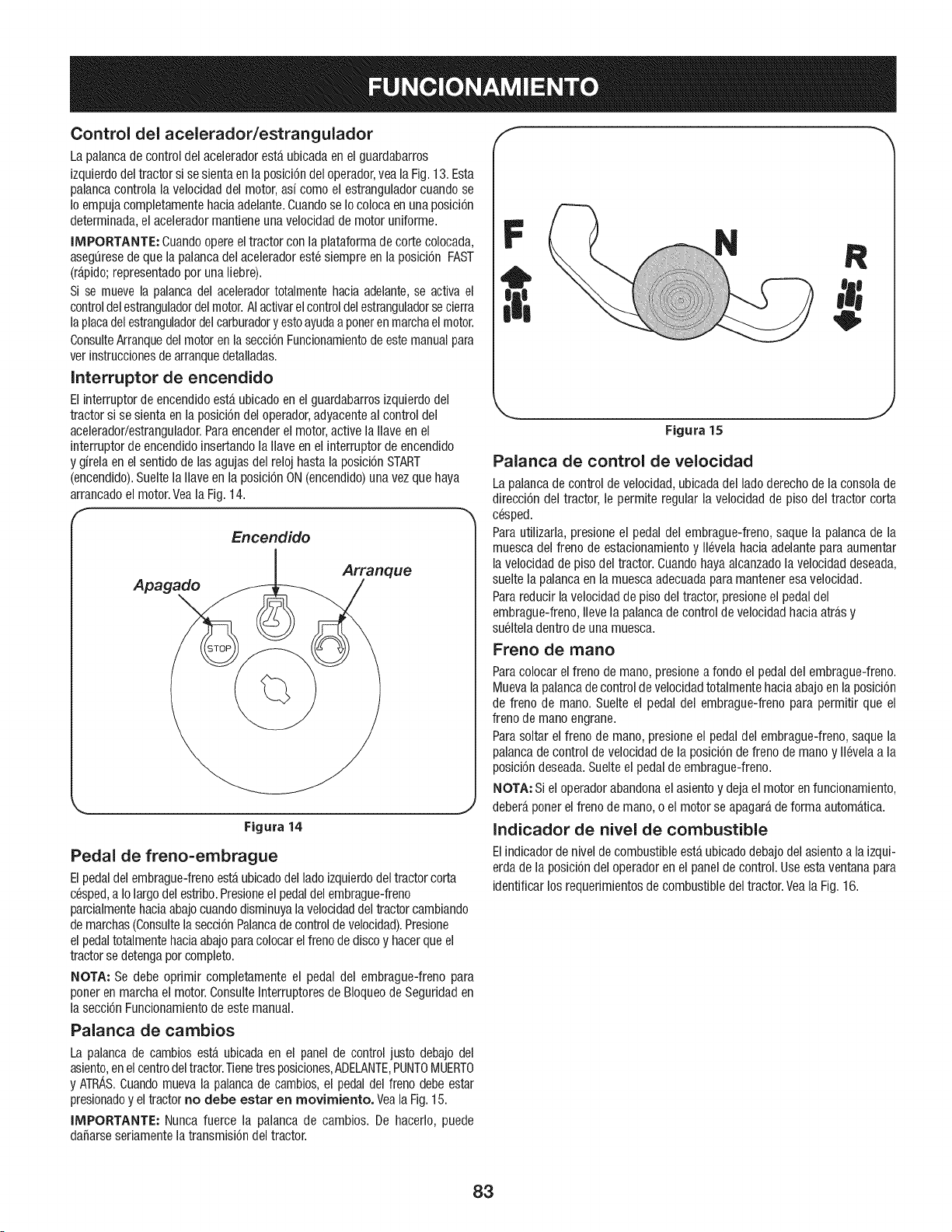
Control del acelerador/estrangulador
La palancade control del acderadoresta ubicada en el guardabarros
izquierdodel tractor si sesientaen laposici6ndel operador,vea laFig.13.Esta
palancacontrola la velocidaddel motor,asi como el estranguladorcuandose
Io empujacompletamentehaciaadelante.Cuandose Iocolocaen unaposici6n
determinada,el aceleradormantieneuna velocidadde motoruniforme.
IMPORTANTE: Cuandoopereel tractor con la plataformade corte colocada,
aseguresede que lapalanca del aceleradoreste siempre en la posici6n FAST
(rapido;representadopor una liebre).
Si se mueve la palancadel aceleradortotalmentehaciaadelante,se activa el
controldelestranguladordelmotor.AIactivarelcontroldelestranguladorsecierra
laplacadelestranguladordelcarburadory esto ayudaa poneren marchael motor.
ConsulteArranquedel motoren lasecci6nFuncionamientode este manualpara
verinstruccionesde arranquedetalladas.
Interruptor de encendido
Elinterruptorde encendidoesta ubicado en el guardabarrosizquierdodel
tractor si se sienta en la posici6ndel operador,adyacenteal control del
acelerador/estrangulador.Paraencenderel motor,active la Naveen el
interruptorde encendidoinsertandola Naveen el interruptorde encendido
y girela en el sentidode las agujasdel reloj hastala posicionSTART
(encendido).Suelte la Naveen la posici6nON(encendido)una vezquehaya
arrancadoel motor.Veala Fig.14.
f
Encendido
Apagado
Arranque
Figura 14
Pedal de freno=embrague
Elpedaldel embrague-frenoestaubicadodel lado izquierdodel tractorcorta
cesped,a Io largodel estribo.Presioneel pedaldel embrague-treno
parcialmentehaciaabajocuandodisminuyalavelocidaddeltractor cambiando
de marchas(Consultelasecci6nPalancade control de veloddad).Presione
el pedaltotalmentehaciaabajoparacolocarel frenode discoy hacerqueel
tractorse detengapor completo.
NOTA: Se debe oprimir completamente el pedal del embrague-freno para
poneren marchael motor.ConsulteInterruptoresde BIoqueode Seguridaden
la secci6nFuncionamientode estemanual.
Palanca de cambios
La palancade cambiosesta ubicadaen el panel de controljusto debajo del
asiento,en elcentrodeltractor.Tienetresposiciones,ADELANTE,PUNTOMUERTO
y ATRAS.Cuandomueva la palancade cambios,el pedaldel freno debeestar
presionadoy eltractor no debe estar en rnovirniento. Veala Fig.15.
IMPORTANTE: Nunca fuerce la palanca de cambios. De hacerlo, puede
daSarseseriamentela transmisi6ndel tractor.
/f
N
J
Figura 15
Palanca de control de velocidad
La palancade control de velocidad,ubicadadel ladoderecho de la consolade
direcci6n del tractor, le permite regular la velocidadde piso del tractor corta
cesped.
Parautilizarla, presioneel pedaldel embrague-freno,saque la palancade la
muescadel freno de estadonamientoy llevelahacia adelantepara aumentar
lavelocidadde piso del tractor. Cuandohayaalcanzadola velocidaddeseada,
suelte la palancaen la muescaadecuadaparamanteneresavdocidad.
Pararedudr la velocidadde pisodel tractor, presioneel pedaldel
embrague-freno,Ilevela palancadecontrol de veloddadhacia atras y
suelteladentro de una muesca.
Freno de mano
Paracolocar el freno de mano,presionea rondoel pedal del embrague-freno.
Muevalapalancade controlde velocidadtotalmentehacia abajoen la posid6n
de freno de mano.Suelte el pedal del embrague-freno para permitir que el
freno de mano engrane.
Parasoltar el freno de mano,presioneel pedaldel embrague-freno,saque la
palancade control de vdocidadde la posici6nde freno de mano y ll6vela a la
posici6ndeseada.Sudte el pedalde embrague-freno.
NOTA; Siel operadorabandonael asientoy dejael motor enfuncionamiento,
debera ponerelfreno de mano,o el motor seapagarade forma automatica.
Indicador de nivel de combustible
Elindicadorde nivd de combustibleesta.ubicadodebajodel asientoa laizqui-
erdade la posici6ndel operadoren el panelde control.Useestaventanapara
identificarlosrequerimientosde combustibledel tractor.Veala Fig.16.
83
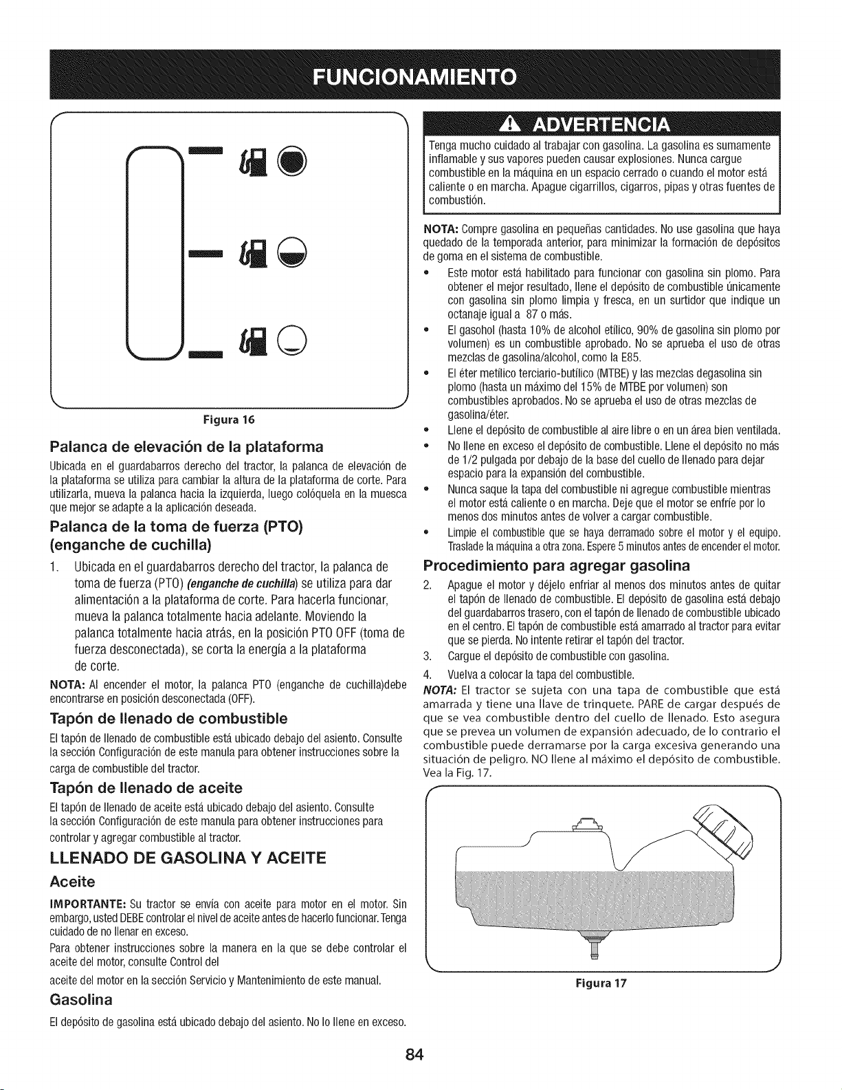
©
Figura 16
Palanca de elevaci6n de la plataforma
Ubicadaen el guardabarrosderecho del tractor, la palanca de elevaci6nde
la plataforma se utiliza para cambiar la altura de la plataforma de corte. Para
utilizarla,mueva la palancahacia la izquierda,luegocol6quelaen la muesca
quemejor seadaptea la aplicaci6ndeseada.
Palanca de la toma de fuerza (PTO)
(enganche de cuchiiia)
1. Ubicada en el guardabarros derecho del tractor, la palanca de
toma de fuerza (PT0) (enganche de cuchilla) se utiliza para dar
alimentaci6n a la plataforma de corte. Para hacerla funcionar,
mueva la palanca totalmente hacia adelante. Moviendo la
palanca totalmente hacia atras, en la posici6n PT0 OFF (toma de
fuerza desconectada), se corta la energia a la plataforma
de corte.
NOTA: AI encender el motor, la palanca PT0 (enganchede cuchilla)debe
encontrarseenposici6ndesconectada(OFF).
Tapon de llenado de combustible
Eltap6ndeIlenadode combustibleesta ubicadodebajodel asiento.Consulte
la secci6n Configuraci6nde estemanulapara obtenerinstruccionessobre la
carga de combustibledel tractor.
Tap6n de llenado de aceite
Eltap6ndellenadode aceiteesta ubicadodebajo del asiento.Consulte
la secci6n Configuraci6nde estemanulapara obtenerinstruccionespara
controlary agregarcombustibleal tractor.
LLENADO DE GASOLINA Y ACEITE
Aceite
IMPORTANTE: Su tractor se envfacon aceite para motor en el motor.Sin
embargo,ustedDEBEcontrolarelniveldeaceiteantesde hacerlofuncionar.Tenga
cuidadode no Ilenaren exceso.
Para obtener instruccionessobre la manera en la que se debe controlar el
aceitedel motor,consulteControldel
aceitedel motor en la secci6nServicioy Mantenimientode este manual.
Gasolina
Tengamuchocuidadoal trabajarcon gasoNna.La gasolina es sumamente
inflamabley sus vaporespuedencausar explosiones.Nunca cargue
combustibleen la maquinaen un espaciocerradoo cuando el motorest,,
calienteo en marcha.Apaguecigarrillos,cigarros, pipas y otras fuentes de
combusti6n.
NOTA: Compregasolinaen peque_ascantidades.No use gasoNnaque haya
quedadode la temporadaanterior,para minimizar la formaci6nde dep6sitos
de gomaen el sistemade combustible.
• Este motor esta habilitadopara funcionar con gasolinasin plomo.Para
obtenerel mejor resultado,Ileneel dep6sitode combustibleOnicamente
con gasolinasin plomo limpia y fresca, en un surtidor que indique un
octanajeigual a 87 o mas.
El gasohol(hasta10% de alcoholetilico, 90% de gasoNnasin plomopor
volumen) es un combustible aprobado.No se aprueba el uso de otras
mezdas de gasoNna/alcohol,como laE85.
El eter metilico terciario-butilico (MTBE)y las mezclasdegasolinasin
plomo (hastaun maximodel 15% de MTBEpor volumen)son
combustiblesaprobados.Nose apruebael uso de otras mezclasde
gasolina/eter.
Llene eldep6sitode combustibleal aire libreo en un areabien ventilada.
No llene en excesoel dep6sitode combustible.Llene eldep6sito no mas
de 1/2 pulgadapordebajode labasedel cuello de llenadopara dejar
espaciopara la expansi6ndel combustible.
Nuncasaque latapa del combustibleni agreguecombustiblemientras
el motorestacalienteo en marcha.Dejeque el motorse enfrie por Io
menos dos minutos antesde volvera cargar combustible.
Limpieel combustibleque se hayaderramadosobreel motory el equipo.
Trasladelamaquinaaotrazona.Espere5 minutosantesde encenderelmotor.
Procedimiento para agregar gasolina
2. Apague el motor y dejelo enfriar al menos dos minutos antes de quitar
el tap6n de Ilenadode combustible.Eldep6sitode gasolinaesta debajo
del guardabarrostrasero,conel tap6nde Ilenadodecombustibleubicado
en elcentro.Eltap6n de combustibleestaamarradoaltractor para evitar
que se pierda.Nointente retirar el tap6ndel tractor.
3. Cargueel dep6sitode combustiblecon gasolina.
4. Vuelvaa colocar latapa del combustible.
NOTA: El tractor se sujeta con una tapa de combustible que est_
amarrada y tiene una Nave de trinquete. PAREde cargar despu_s de
que se vea combustible dentro del cuello de Ilenado. Esto asegura
que se prevea un volumen de expansi6n adecuado, de Io contrario el
combustible puede derramarse pot la carga excesiva generando una
situaci6n de peligro. NO Ilene al m_ximo el dep6sito de combustible.
Vea la Fig. 17.
Figura 17
Eldep6sitode gasolinaesta ubicadodebajo del asiento.NoIo Ileneen exceso.
84
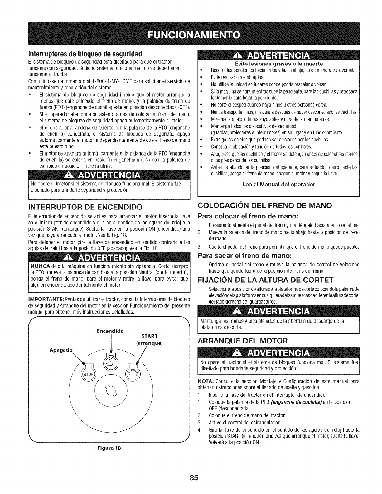
Interruptoresde bioqueo de seguridad
Elsistemade bloqueode seguridadestadiseSadoparaque el tractor
funcionecon seguridad.Si dichosistemafuncionamal,no se debe hacer
funcionarel tractor.
Comunfquesede inmediato al 1-800-4-MY-HOMEpara solicitar el serviciode
mantenimientoy reparaci6ndel sistema.
• El sistema de bloqueo de seguridadimpide que el motor arranque a
menos que este colocado el freno de mane,y la palancade toma de
fuerza(PTO)(enganchede cuchilla)este en posici6ndesconectada(OFF).
Si el operadorabandonasu asiento antes de colocar el freno de mane,
el sistemade bloqueode seguridadapagaautomaticamenteel motor.
Si el operadorabandonasu asiento con la palancade la PTO(enganche
de cuchiNa)conectada, el sistema de bloqueo de seguridad apaga
automaticamenteel motor,independientementede queel frenode mane
estepuestoo no.
Elmotor seapagaraautomaticamentesi la palancade la PTO(enganche
de cuchilla) se coloca en posici6n enganchada(ON)con la palanca de
cambiosen posici6nmarchaatras.
Noopereel tractor si el sistemade bloqueofuncionamal. Elsistemarue
diseSadopara brindarle seguridady protecci6n.
Evite lesiones graves o la muerte
• Recorralaspendienteshaciaarribay haciaabajo,node maneratransversal.
• Eviterealizargirosabruptos.
• Noutilicelaunidadenlugaresdondepodrfaresbalarovolcar.
• Si lamaquinaseparamientrassubelapendiente,parelascuchillasy retroceda
lentamenteparabajarlapendiente.
• Nocorteelc6spedcuandohayaniSosu otraspersonascerca.
• NuncatransporteniSos,nisiquieradespuesdehaberdesconectadolascuchillas.
• Mirehaciaabajoy detrassuyoantesy durantelamarchaatras.
• Mantengatodoslosdispositivosde seguridad
(guardas,protectorese interruptores)en sulugaryen funcionamiento.
• Extraigalosobjetosquepodrfanserarrojadosporlascuchillas.
• Conozcalaubicaci6ny funci6nde todosloscontroles.
• AsegOresequelascuchillasy elmotorsedetenganantesdecolocarlas manos
o lospiescercadelascuchillas.
• Antesde abandonarla posici6ndeloperador,pareel tractor,desconectelas
cuchillas,pongael frenodemano,apagueelmotory saquela Nave.
Lea el Manual del operador
INTERRUPTOR DE ENCENDIDO
El interrupter de encendidose activa paraarrancar el motor. Insertela Nave
en el interrupterde encendidoy gire en el sentido de lasagujas del reloj a la
posici6nSTART(arranque).Suelte la Naveen la posici6nON(encendido)una
vezque hayaarrancadoel motor.Veala Fig.18.
Para detenerel motor,gire la Navede encendidoen sentido contrario alas
agujasdel reloj hastala posici6nOFF(apagado).Veala Fig.18.
NUNCA deje la maquinaen funcionamientosin vigilancia.Corte siempre
la PTO,muevala palancade cambiosa la posici6nNeutral (puntomuerto),
ponga el freno de mane, pare el motor y retire la Nave,para evitar que
alguienenciendaaccidentalmenteel motor.
IMPORTANTE: PAntesde utilizar el tractor,consulteInterruptoresde bloqueo
de seguridadyArranque del motoren lasecci6nFuncionamientodel presente
manualpara obtenermasinstruccionesdetalladas.
Apagade
Encendido
START
(arranque)
Figura 18
J
COLOCACION DEL FRENO DE MANO
Para colocar el freno de mano:
1. Presionetotalmenteelpedaldelfreno y mantengalohaciaabajocon elpie.
2. Muevala palancadel frenode manohaciaabajohastala posici6nde freno
de mano.
3. Suelteel pedaldel frenoparapermitirqueel frenode manoquedepuesto.
Para sacar el freno de mano:
1. Oprimael pedal del freno y mueva la palanca de control de velocidad
hastaque quedefuera de la posici6nde freno demano.
FIJACION DE LA ALTURA DE CORTET
1. Seleccionelaposici6ndealturadelaplatatormadecortecolocandolapalancade
elevaci6ndelaplataformaencualquieradelasmuescasdediferentealturadecorte,
del ladederechodel guardabarros.
Mantengalas manosy pies alejadosde la aberturade descargade la
plataformade corte.
ARRANQUE DEL MOTOR
No opere el tractor si el sistemade bloqueofunciona real. El sistema rue
dise_adopara brindarleseguridady protecci6n.
NOTA: Consulte la secci6n Montaje y Configuraci6nde este manual para
obtenerinstruccionessobreel Ilenadode aceitey gasolina.
1. Insertela llave deltractor en el interruptorde encendido.
1. Coloquela palancade la PTO(enganche decuchilla) en la posici6n
OFF(desconectada).
2. Coloqueel frenode manodel tractor.
3. Active el controldel estrangulador.
4. Girela Navede encendidoen el sentido de las agujasdel reloj hasta la
posici6nSTART(arranque).Unavez quearranqueel motor,sueltela Ilave.
Volveraa la posici6nON.
85
IMPORTANTE:NOmantengala Ilaveen la posici6nSTART(arranque)
durantemas de diezsegundospor vez. SiIo hace,puedeocasionarda_os
al arrancadorelectrico del motor.
5. Despuesde quearranqueel motor,desactiveel control del obturadory
coloqueel control del aceleradoren la posici6nFAST(velocidadrapida).
NOTA: Si Io hace,segenerarAunamezcla"rica" de combustibles,Io cual
hara queel motor pierdapotencia.
DETENOI6N DEL MOTOR
Si golpeacontra algunobjeto extra,o, detengael motor,desconecteel(los)
cable(s)de la bujfay conecteel motora masa.Inspeccione
minuciosamentela maquinapara ver si estA daSada.Repareelda_o antes
de volvera encenderel motor y operarla maquina.
1. Si las cuchillasestan enganchadas,coloquela palancade la PTO
(engancfle de cucflilla)en la flosici#n OFF(desconectada).
2. Gire la Navede encendidoen sentidocontrario alas agujasdel reloj a la
posici6nSTOP(parar).
3. Retirela Ilavedel interruptorde encendidopara evitar quealguien
enciendaaccidentalmenteelmotor.
CONDUCClON DEL TRACTOR
Evitearrancars0bitamente,desarrollarexcesivavelocidady
detenersederepente.
Noabandoneel asientodel tractor sin colocar primerola PTO(enganchede I
cuchilla) en la posici6n OFF(desconectada),presionarel pedaldel freno y
colocarel freno de estacionamiento.Si dejael tractor sin vigilancia,apague
e motory ret re a ave de encenddo. I
1
y mueva
hastaque quedefuera de la posici6nde freno de mano,luegodeje que
se suelteel freno.
2. Mueva la palanca del acelerad zor a la posici6n FAST(VELOCIDAD
RAPIDA,representadapor unaIiebre).
3. Coloquela palancadecambiosen posici6nFORWARD(marchaadelante)
o REVERSE(marchaatras).
IMPORTANTE: NOuse la palanca de cambios para cambiarla direcci6n de
desplazamientomientras el tractor esteen movimiento.Siempre use el pedal
de freno paradetener el tractor por completoantesde hacerel cambio.
4. Suelteelfreno de manopresionandoel pedaldel embrague-frenoy
colocandola palancade control de velocidaden la posici6ndeseada.
IMPORTANTE: QuienesutiNcenla mAquinapor primeravezdebenusar las
posicionesde velocidad 1 6 2. Familiarfcesepor completocon el
funcionamientoy los controlesdel tractor antes de operar la maquinaen
posicionesde mayorvelocidad.
5. Suelteel pedaldel embrague-frenolentamenteparaponerla unidad en
movimiento.
6. El tractor corta cespedse detienepresionandoel pedaldel
embrague-freno.
NOTA: AIoperarla unidadinicialmente,habrapocadiferenciaentre lasdos
velocidadesmasaltas hastaque lascorreasse hayanasentadoen las poleas
duranteel periodode ablande.
Antesde abandonarla posici6ndel operador,desenganchelascuchillas,
coloquela palancaen neutral,coloque elfreno de estacionamiento,
apagueel motor y retire la Ilavede encendido.
IMPORTANTE: Siempreque detengael tractor por cualquierraz6nen un
area de cesped,haga Io siguiente:
1. Coloquela palancade cambiosen punto muerto,
2. Coloqueelfreno de mano,
3. Apagueel motory retire la llave.Esopermitirareducir al minimo la
posibilidadde que su cespedresulte "quemado" por el escapecaliente
del motoren funcionamiento.
Si la unidadse detienecon el control de velocidaden la posici6ndealta
velocidad,o si la unidadnofuncionacon la palancade controlde velocidad
en la posici6nde bajavelocidad,realice Io siguiente:
1. Coloquela palancade cambiosen posici6nNEUTRAL(punto muerto).
2. Vuelvaa encenderel motor.
3. Coloquela palancade control de velocidaden la posici6nde velocidad
mas alta.
4. Sueltecompletamenteel pedaldel embrague-freno.
5. Presioneel pedaldel embrague-freno.
6. Coloquela palancade control de velocidaden la posici6ndeseada.
7. Coloquela palancade cambiosen la posici6nFORWARD(marcha
adelante)o REVERSE(marchaatras),y siga el procedimientonormalde
operaci6n.
OPERAOI()N EN PENDIENTES
Consulteel INDICADORDEPENDIENTESen la secci6nInstruccionesde
seguridaddel manualpara contribuir a determinaren que pendientespuede
operarel tractor con seguridad.
No corte en pendientescon unainclinaci6nde mas de15 grados
(elevaci6naproximadade2 1/2 pies por cada 10 pies). El tractor podria
voltearsey causarlesionesseveras.
• En las pendientescorte haciaarribay haciaabajo, NUNCAenforma
transversal.
• Tengamuchocuidadoal cambiar de direcci6nen unapendiente.
• Este atentoa los hoyos,surcos,baches,rocasu otros objetosocultos.
Elterrenodesniveladopuedevoltearlamaquina.Elcespedalto puede
ocultar obstaculos.
• Evite realizargiros cuandoopereen unapendiente.Si debe realizarun
giro, hagalohacia abajode la pendiente.Subirunapendienteaumenta
enormementelas posibilidadesde que el vehiculode unavueltade
campana.
• Evitedetenersecuandosubauna pendiente.Si fuese necesario
detenersemientrassubeuna pendiente,arranquesuavey cuidadosa-
mente para reducirla posibilidadde que eltractor se de vueltahacia
atras.
86
ENGANCHE DE LAS CUCHILLAS
AIconectarla PTO(enganchede cuchiNa)se suministraalimentaci6na la
plataformade corte. Paraconectarlas cuchillas,haga Iosiguiente:
1. Muevala palancade control del acelerador/estranguladora la posici6n
FAST(VELOCIDADRD,PIDA,representadapor una liebre).
2. Tomela palancade la PTO(enganchede cuchilla)y gfrelatotalmente
haciaadelantea la posici6nON (enganchada).
3. Mantengala palancadel aceleradoren la posicionFAST(rApido;
representadapor una liebre),paraun uso mas eficazde la plataforma
de corte.
NOTA_ Elmotorse apagaraautomaticamentesi la palancade la PTO
(enganchede cuchilla)se colocaen posici6nenganchada(ON)con la palanca
de cambiosen posici6nmarchaatras.
ABONO
Se encuentradisponiblecomoaccesorioun kit deabono.Elabonoesun
procesopor el cual se recirculan los recortesde cesped de manerarepetida
debajode la plataformade corte.Los recortesmuy finos luego son
despedidoshaciaatras para quese depositenen el cespedy actuencomo
fertilizantenatural.
Se puedeadquirir un kit de abono.Consulteal distribuidor a quien le compr6
estacortadorade cespedparaobtener masinformacion.
UTILIZACiON DE LA PALANOA DE
ELEVAOION DE LA PLATAFORMA
Paraelevarla plataformade corte, muevala palancade elevaci6nde la
plataformahacia la izquierday col6quelaen la muescaque mejorse adapte
a la aplicaci6ndeseada.ConsulteAjustede laaltura de corte unaspaginas
atras en estamisma secci6n.
CORTE DE Ci=SPED
Paratratar de evitar el contactocon lascuchillaso unalesi6n por algun
objeto quesea arrojado,mantengaa los observadores,a los ayudantes,
niSosy mascotasalejadosal menos75 pies (25 metros) de la maquina
mientras esta enfuncionamiento.Detengala maquinasi alguien se acerca.
Lasiguiente informaci6nsera de utilidad cuandouse la plataformade corte
con su tractor:
Planifiqueel patr6nde corte, para evitarque la descargade materiales se
realice hacia los caminos,las veredas,losobservadores,etc. Eviteademas
descargarmaterialcontra una paredu obstrucci6n, ya que esto podrfa
hacer que el materialdescargadorebotecontra el operador.
Nocorte a alta velocidadabsoluta,especialmentesi tiene instaladoun
kit deabonoo un colector de cesped.
• Paraobtener los mejoresresultados,se recomiendarealizarlosdos
primeroscortes de cespedarrojandola descargahacia el centro.
Despuesde lasdos primerasvueltas,cambie la direcci6n paraarrojar la
descargahaciaafuera,paraequilibrar elcorte. Estootorgaraun mejor
aspectoal cesped.
Nocorte elcespeddemasiadocorto.El cespedcorto es propicio parael
crecimientode malezasy se poneamarillorapidamentecuando escasea
laIluvia.
Elcorte del cespedsiempredeberealizarsecon el reguladordel motor
al maximo.
• Enterrenosdificiles, puederesultarnecesariopasar por segundavez el
tractor corta cespedsobre el area ya cortada,paraobtener un corte mas
prolijo.
• NOintente cortarmalezasfrondosaso cespedextremadamentealto.El
tractor fue disefiadopara cortar el cesped,NOpara podarmalezas.
• Mantengala cuchillaafilada y cambiela cuandose gasten.Consulte
Cuchillade corte en lasecciOnMantenimientode este manualpara
obtenerinstruccionessobrecomoafilar correctamentelascuchillas.
Losfaros se apagan(OFF)cuandosecolocala Navede encendidoen la
posici6nSTOP.
87
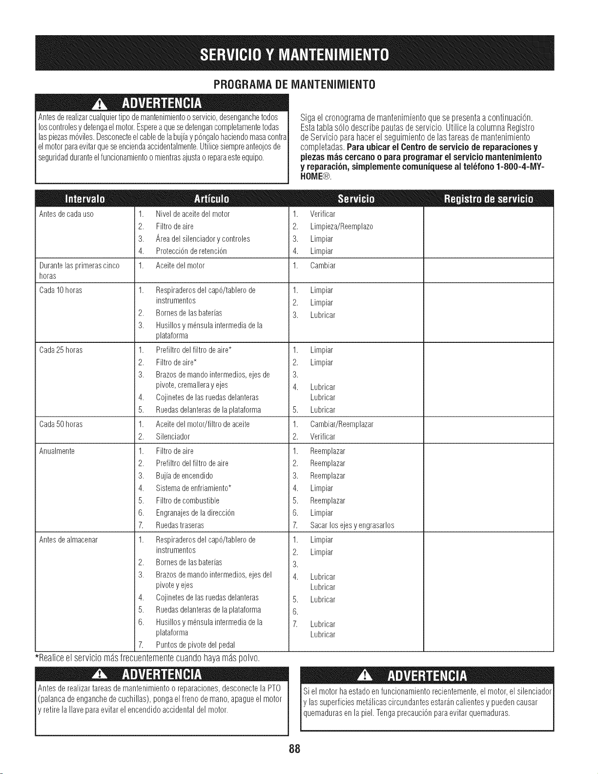
PROGRAIVlADEiVlANTENliVllENTO
Antesde realizarcualquiertipo demantenimientoo servicio,desenganchetodos
loscontrolesy detengaelmotor.Esperea quesedetengancompletamentetodas
laspiezasm6viles.Desconecteelcablede labuj[ay p6ngalohaciendomasacontra
elmotorparaevitarqueseenciendaaccidentalmente.Utilicesiempreanteojosde
seguridadduranteelfuncionamientoomientrasajustaoreparaesteequipo.
Antesdecadauso
Durantelasprimerascinco
horas
Cada10horas
Cada25 horas
Cada50 horas
Anualmente
Antes de almacenar
1. Niveldeaceitedelmotor
2. Filtrodeaire
3. Areadelsilenciadorycontroles
4. ProtecciOnde retenciOn
1. Aceitedel motor
1. Respiraderosdel cap6/tablero de
instrumentos
2. Bornes de las bater[as
3. Husillos y m6nsula intermedia de la
plataforma
1. Prefiltro del filtro de aire*
2. Filtro deaire*
3. Brazosde mandointermedios, ejes de
pivote, cremalleray ejes
4. Cojinetes de las ruedas delanteras
5. Ruedasdelanteras de la plataforma
1. Aceite del motor/filtro de aceite
2. Silenciador
1. Filtro deaire
2. Prefiltro del filtro de aire
3. Bujia de encendido
4. Sistema de enfriamiento*
5. Filtro decombustible
6. Engranajesde la direcci6n
7. Ruedastraseras
1. Respiraderosdel cap6/tablero de
instrumentos
2. Bornes de las bater[as
3. Brazosde mandointermedios, ejes del
pivote y ejes
4. Cojinetes de las ruedas delanteras
5. Ruedasdelanteras de la plataforma
6. Husillos y m6nsula intermedia de la
plataforma
7. Puntos de pivote del pedal
*Realice el servicio m_s frecuentemente cuando hayam_s polvo.
Antesde realizartareasdemantenimientoo reparaciones,desconectela PTO
(palancadeenganchede cuchillas),pongaelfreno de mano,apagueel motor
retirela Ilaveparaevitarel encendidoaccidentaldel motor.
Sigaelcronogramade mantenimientoquesepresentaacontinuaciOn.
Estatablasolodescribepautasdeservicio.UtilicelacolumnaRegistro
deServicioparahacerel seguimientodelastareasdemantenimiento
completadas.Paraubicarel Centrode serviciode reparacionesy
piezasm_scercanoo paraprogramarel serviciornantenimiento
y reparaci6n,sirnplementecomuniqueseal telbfono l=800-4-1VlY=
HOME®.
1. Verificar
2. Limpieza/Reemplazo
3. Limpiar
4. Limpiar
1. Cambiar
1.
2.
3.
Limpiar
Limpiar
Lubricar
1.
2.
3.
4. Lubricar
Lubricar
5. Lubricar
1. Cambiar/Reemplazar
2. Verificar
1. Reemplazar
2. Reemplazar
3. Reemplazar
4. Limpiar
5. Reemplazar
6. Limpiar
7. Sacarlosejesy engrasarlos
1. Limpiar
2. Limpiar
3.
4. Lubricar
Lubricar
Lubricar
Limpiar
Limpiar
5.
6.
7. Lubricar
Lubricar
Siel motorha estadoen funcionamientorecientemente,el motor,el silenciador
y lassuperficiesmetalicascircundantesestarancalientesy puedencausar
quemadurasen a pe. Tengaprecauc6n paraevtar quemaduras.
I}8
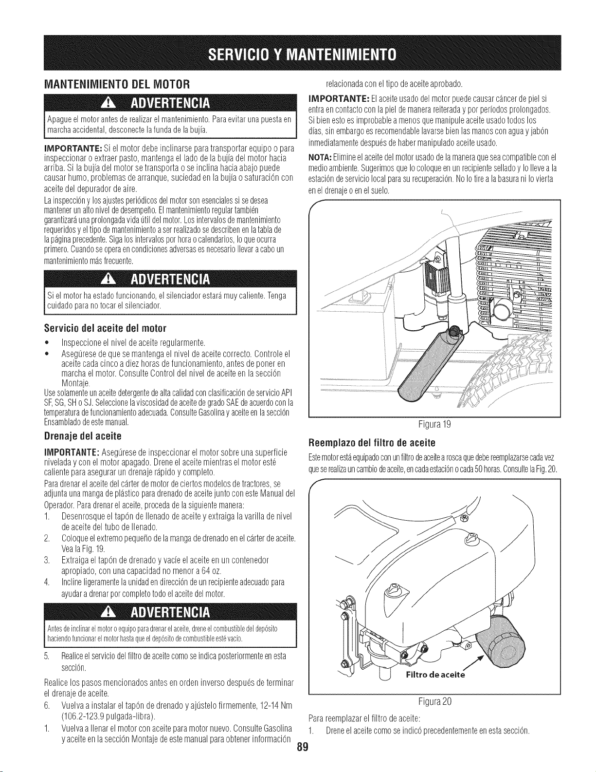
iVlANTENliVllENTODELMOTOR
Apagueel motorantesde realizarel mantenimiento.Paraevitarunapuestaen
marchaaccidental,desconectelafunda de labuj[a.
IMPORTANTE:Sielmotordebeinclinarseparatransportarequipoo para
inspeccionaro extraerpasto,mantengael ladodelabujiadelmotorhacia
arriba.Silabujiadelmotorsetransportaoseinclinahaciaabajopuede
causarhumo,problemasdearranque,suciedadenla bujiao saturaciOncon
aceitedeldepuradordeaire.
LainspecciOny losajustesperiOdicosdelmotorsonesencialessisedesea
mantenerunaltoniveldedesempeno.Elmantenimientoregulartambi@
garantizaraunaprolongadavidatitildelmotor.Losintervalosdemantenimiento
requeridosy eltipodemantenimientoaserrealizadosedescribenenlatablade
lapaginaprecedente.Sigalosintervalosporhoraocalendarios,Ioqueocurra
primero.CuandoseoperaencondicionesadversasesnecesarioIlevaracaboun
mantenimientomasfrecuente.
Siel motorhaestadofuncionando,el silenciadorestaramuycaliente.Tenga
cuidadoparanotocar elsilenciador.
Servicio del aceite del motor
* Inspeccioneel niveldeaceiteregularmente.
* Aseguresedequesemantengael niveldeaceitecorrecto.Controleel
aceitecadacincoa diezhorasdefuncionamiento,antesdeponeren
marchaelmotor.ConsulteControldelniveldeaceiteenlasecciOn
Montaje.
UsesolamenteunaceitedetergentedealtacalidadconclasificaciOndeservicioAPI
SF,SG,SHoSJ.SeleccionelaviscosidaddeaceitedegradoSAEdeacuerdoconla
temperaturadefuncionamientoadecuada.ConsulteGasolinayaceiteenlasecciOn
Ensambladodeestemanual.
Drenaje del aceite
ilVIPORTANTE:Aseg0resedeinspeccionarelmotorsobreunasuperficie
niveladay conelmotorapagado.Ureneel aceitemientraselmotorest6
calienteparaasegurarun drenajerapidoy completo.
Paradrenarelaceitedelcarterdemotordeciertosmodelosdetractores,se
adjuntaunamangadeplasticoparadrenadodeaceitejuntoconesteManualdel
Operador.Paradrenarelaceite,procedadelasiguientemanera:
1. Desenrosqueel tap@deIlenadodeaceitey extraigalavarilladenivel
deaceitedeltubodeIlenado.
2. Coloqueelextremopeque_odelamangadedrenadoenelcarterdeaceite.
VealaFig.19.
3. Extraigaeltap@dedrenadoy vacieelaceiteenuncontenedor
apropiado,conunacapacidadnomenora64oz.
4. Inclineligeramentela unidadendirecciOndeunrecipienteadecuadopara
ayudaradrenarporcompletotodoelaceitedelmotor.
Antesdeinclinarelmotoroequipoparadrenarelaceite,dreneelcombustibledd dep6sito
haciendofuncionarelmotorhastaqueeldepOsitodecombustibleest6vacfo.
5. Realiceelserviciodelfiltrodeaceitecomoseindicaposteriormenteenesta
secci6n.
Realicelospasosmencionadosantesenordeninversodespu6sdeterminar
eldrenajedeaceite.
6. Vuelvaainstalarel tap@dedrenadoy ajustelofirmemente,12-14Nm
(106.2-123.9pulgada-libra).
1. VuelvaaIlenarel motorconaceiteparamotornuevo.ConsulteGasolina
yaceiteenlasecciOnMontajedeestemanualparaobtenerinformaciOn
relacionadaconeltipodeaceiteaprobado.
IIVIPORTANTE:Elaceiteusadodelmotorpuedecausarcancerdepielsi
entraencontactoconlapieldemanerareiteraday porperiodosprolongados.
Sibienestoesimprobableamenosquemanipuleaceiteusadotodoslos
dias,sinembargoesrecomendablelavarsebienlasmanosconaguay jab@
inmediatamentedespu6sdehabermanipuladoaceiteusado.
NOTA:Elimineelaceitedelmotorusadodelamaneraqueseacompatibleconel
medicambiente.SugerimosqueIocoloqueenunrecipienteselladoy IoIlevea la
estaci0ndeserviciolocalparasurecuperaci0n.NoIotirealabasurani Iovierta
eneldrenajeoenel suelo.
\
Figura19
Reemplazo del filtro de aceite
Fstemotorestaequipadoconunfiltrodeaceitearoscaquedebereemplazarsecadavez
queserealizauncambiodeaceite,encadaestaci6nocada50horas.ConsultelaFig.20.
FiJtro de aceite
Figura20
Parareemplazarel filtro deaceite:
1. Dreneel aceitecomoseindic0precedentementeenestasecci0n.
8g
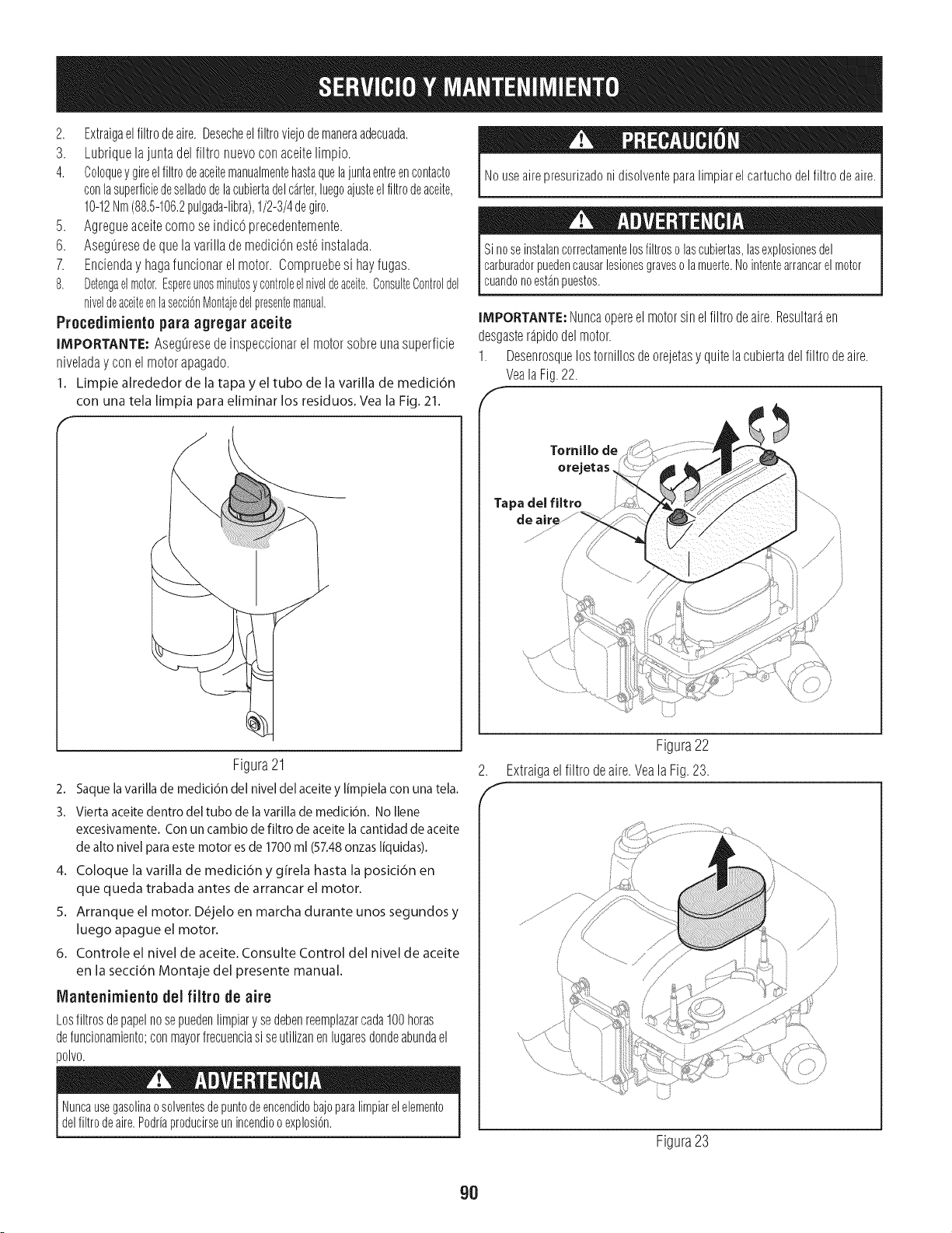
2. Extraigaelfiltrodeaire.Desecheelfiltroviejodemaneraadecuada.
3. Lubriquelajuntadelfiltronuevoconaceitelimpio.
4. Coloqueygireelfiltrodeaceitemanualmentehastaquelajuntaentreencontacto
conlasuperficiedeselladodelacubiertadelc_rter,luegoajusteelfiltrodeaceite,
10-12Nm(88.5-106.2pulgada-libra),1/2-3/4degiro.
5. Agregueaceitecomoseindic6precedentemente.
6. AsegLiresedequelavarillademedici6nest6instalada.
7. Encienday hagafuncionarelmotor.Compruebesi hayfugas.
8. Detengaelmotor.Espereunosminutosycontroleelniveldeaceite.ConsulteControldel
niveldeaceiteenlasecci6nMontajedelpresentemanual.
Procedimiento para agregar aceite
IMPORTANTE:AsegLiresedeinspeccionarel motorsobreunasuperficie
niveladay conel motorapagado.
1. Limpie alrededor de la tapayeltubo de lavarilla de medici6n
con una tela limpia para eliminar los residuos.Veala Fig.21.
Figura21
2. Saquelavarillade medici6ndelniveldelaceitey limpielaconunatela.
3. Viertaaceitedentro del tubo de la varilla de medici6n. No Ilene
excesivamente.Conuncambio de filtro de aceite la cantidad de aceite
de alto nivel para estemotoresde 1700 ml (57.48onzas liquidas).
4. Coloque la varilla de medici6n y girela hasta la posici6n en
que queda trabada antes de arrancar el motor.
5. Arranque el motor. D_jelo en marcha durante unos segundosy
luego apague el motor.
6, Controle el nivel de aceite. Consulte Control del nivel de aceite
en la secci6n Montaje del presente manual.
Nlantenimiento del filtro de aire
Lostiltrosdepapelnosepuedenlimpiarysedebenreemplazarcada100horas
defuncionamiento;conmayorfrecuenciasi seutilizanenlugaresdondeabundael
polvo.
Nuncausegasolinaosolventesdepuntodeencendidobajoparalimpiarelelemento
delfiltrodeaire.Podriaproducirseunincendiooexplosi6n.
Nouseairepresurizadonidisolventepara limpiarelcartuchodelfiltro deaire.
Sinoseinstalancorrectamentelosfiltroso lascubiertas,lasexplosionesdel
carburadorpuedencausarlesionesgraveso lamuerte.Nointentearrancarelmotor
cuandonoest_npuestos.
IMPORTANTE,"Nuncaopereelmotorsinelfiltrodeaire.Resultaraen
desgasterapidodelmotor.
1. Desenrosquelostornillosdeorejetasy quitelacubiertadelfiltrodeaire.
VealaFig.22.
f
Tornillo de
orejetas
Tapa del fUtro
de air_
Figura22
2. Extraigaelfiltro deaire.VealaFig.23.
,f
Figura23
90

,
F
Retireelprefiltrodeespumadealrededordelfiltrodeairedepapel.Consulte
laFig.24.Reemplaceelelementodepapelsiestasucioodanado.Limpieel
elementodeespumaoreemplacelosiestadanado.
Air Filter
L
Tapadel fUtro
de aire
Mantenirnient0 de bujia
Cubierta
Figura24
4. Afin delimpiarelelementodeespuma,I_velocondetergenteliquido
suavey agua.Aprieteu optimaelelementodeespumaparaenjuagar
lasuciedady elagua.NoIo retuerza;si Iohace,podriada_arorasgar
elelementodeespuma.Permitaquesesequebienantesdeusarlo.NO
hbriqueelelementodeespuma.
5. Sujeteelfiltro deairenuevoconel elementodeespuma,paraIocual
debealinearel orificiodelfiltro deaireconel colectordeadmisi6n.Vea
laFig.25.
F
.
/,
/
?
Colector de
admisi6n
Figura25
Sujetelacubiertadelfiltrodeairecomprobandoquequedenalineadas
lasnervadurasplasticasdelacubiertaconlosdispositivosplasticos
delacubiertadelfiltro deaire. ConsultelaFig.26.Girelostornillos
deorejetasmanualmenteenelsentidodelasagujasdel relojhastaque
quedenajustados.Controlesi hayproblemasdealineaci6n.
NOpruebelachispasi noest_labujiadeencendido.NOd6arranquealmotorsi no
est_labujiadeencendido.
Paraasegurarsede queelmotorfuncionebien,labujiadebeteneruna
separaci6ncorrectay debeestarlibrede dep6sitos.
1. Retirelafundadebujiay utiliceunaIlaveparabujiasparaextraerlabujia.
VealaFig.27.
Siel motorha estadofuncionando,elsilenciadorestar_muycaliente.Tenga
cuidadoparanotocarelsilenciador.
Funda de bujia
Figura27
Inspeccionevisualmentelabujia.Eliminelabujiasipresentamucho
desgaste,osi el aislanteestaagrietadooastillado.Limpielabujiaconun
cepillodealambresisevaareutilizar.
89
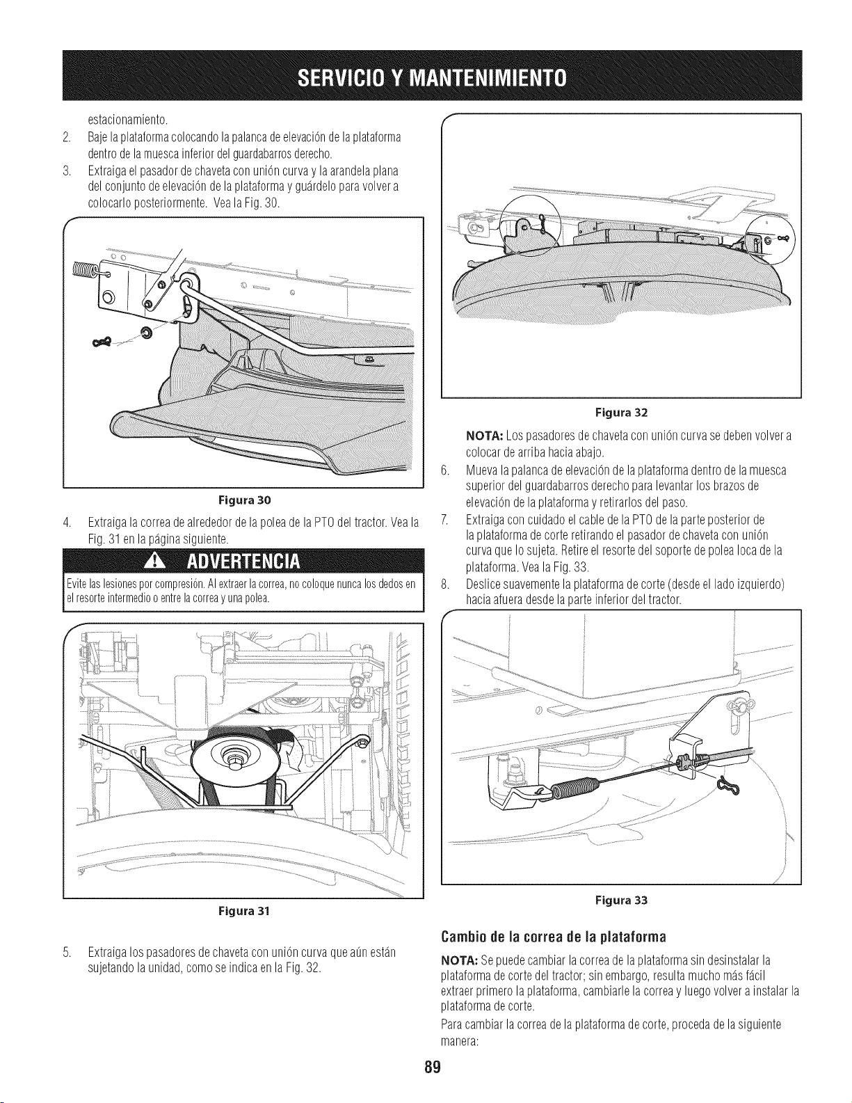
.
3.
estacionamiento.
Bajelaplataformacolocandola palancadeelevaciOndelaplataforma
dentrodelamuescainferiordelguardabarrosderecho.
Extraigaelpasadordechavetaconunioncurvay laarandelaplana
delconjuntodeelevaciOnde laplataformay guardeloparavolvera
colocarloposteriormente.VealaFig.30.
©©
Figura 30
4. Extraigalacorreadealrededordelapoleadela PTOdeltractor.Veala
Fig.31enla paginasiguiente.
EvitelaslesionesporcompresiOn.AIextraerla correa,nocoloquenuncalos@dosen
elresorteintermediooentrelacorreay unapolea.
tf
Figura 32
NOTA: Lospasadoresdechavetaconunioncurvasedebenvolvera
colocardearribahaciaabajo.
6. MuevalapalancadeelevaciOndela plataformadentrode lamuesca
superiordelguardabarrosderechoparalevantarlosbrazosde
elevaciOndelaplataformay retirarlosdelpaso.
7. Extraigaconcuidadoel cabledela PTOdelaparteposteriorde
laplataformadecorteretirandoel pasadordechavetaconunion
curvaqueIosujeta.Retireel resortedelsoportede poleaIocadela
plataforma.VealaFig.33.
8. Deslicesuavementelaplataformadecorte(desdeel ladoizquierdo)
haciaafueradesdelaparteinferiordeltractor.
Figura 31
Figura 33
.
Extraigalospasadoresdechavetaconunioncurvaqueaunestan
sujetandolaunidad,comose indicaenlaFig.32.
Cambio de la correa de la plataforma
NOTA:Sepuedecambiarlacorreadela plataformasindesinstalarla
plataformadecortedeltractor;sinembargo,resultamuchomasfacil
extraerprimerolaplataforma,cambiarlela correay luegovolvera instalarla
plataformadecorte.
Paracambiarlacorreadelaplataformadecorte,procedadelasiguiente
manera:
89
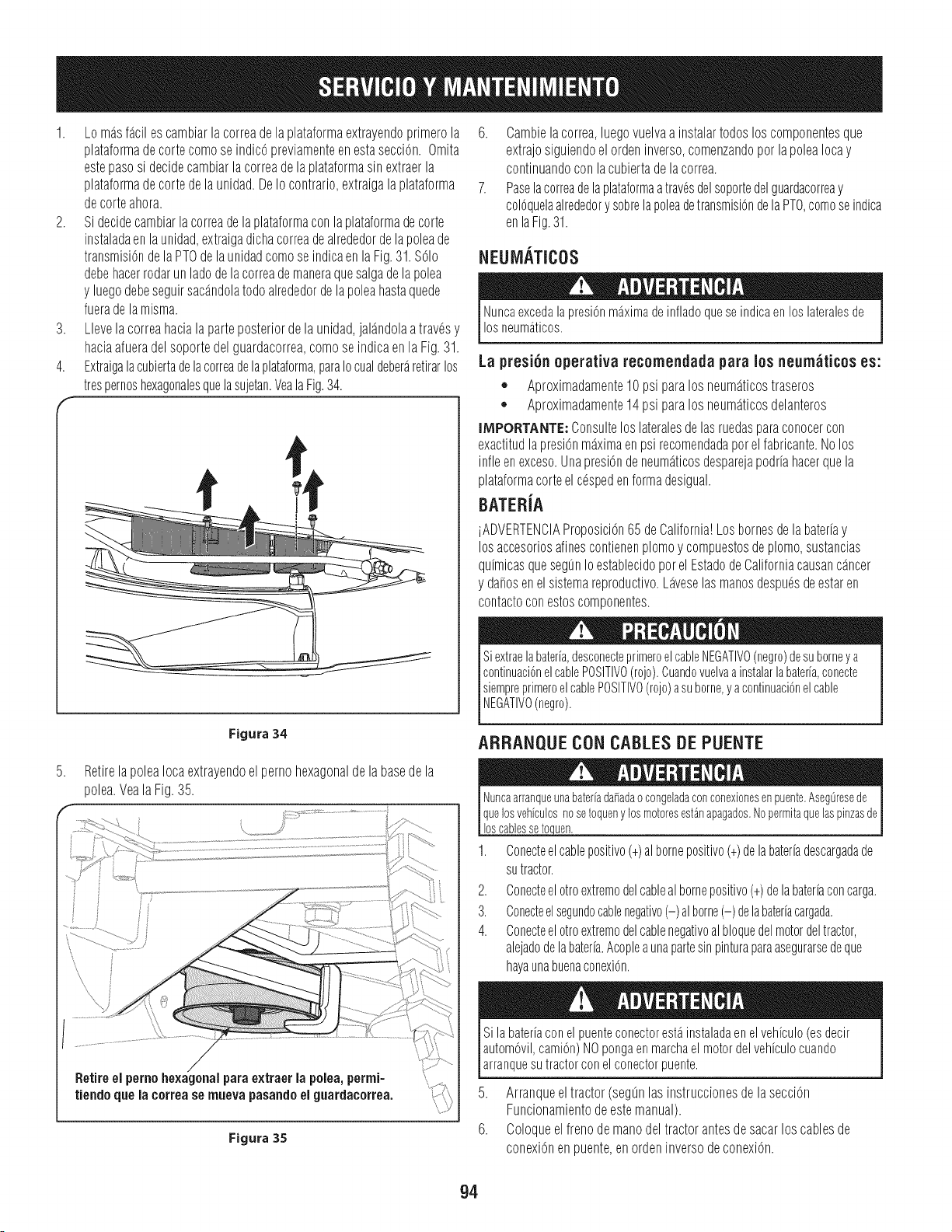
1. Lo masfacilescambiarlacorreadelaplataformaextrayendoprimerola
plataformadecortecomoseindic0previamenteenestasecci0n.Omita
estepasosi decidecambiarla correadelaplataformasinextraerla
plataformadecortedela unidad.DeIo contrario,extraigalaplataforma
decorteahora.
2. Si decidecambiarlacorreade laplataformaconla plataformadecorte
instaladaenlaunidad,extraigadichacorreadealrededordelapoleade
transmisi0ndelaPTOdelaunidadcomoseindicaenlaFig.31.S01o
debehacerrodarunladodelacorreademaneraquesalgadela polea
y luegodebeseguirsacandolatodoalrededordelapoleahastaquede
fueradelamisma.
3. Llevela correahacialaparteposteriordela unidad,jalandolaatravOsy
haciaafueradelsoportedelguardacorrea,comoseindicaenlaFig.31.
4. Extraigalacubiertadelacorreadelaplataforma,paraIocualdeberaretirarlos
trespernoshexagonalesquelasujetan.VealaFig.34.
6. Cambielacorrea,luegovuelvaainstalartodosloscomponentesque
extrajosiguiendoel ordeninverso,comenzandoporlapoleaIocay
continuandoconlacubiertadelacorrea.
7. PaselacorreadelaplataformaatravOsdelsoportedelguardacorreay
colOquelaalrededory sobrelapoleadetransmisiOndelaPTO,comeseindica
enlaFig.31.
NEUM_,TICOS
NuncaexcedalapresiOnmaximade infladoquese indicaen los lateralesde
losneumaticos.
La presi6n operativa recomendada para los neum_ticos es:
,, Aproximadamente10 psiparalos neumaticostraseros
,, Aproximadamente14 psiparalos neumaticosdelanteros
IMPORTANTE:Consulteloslateralesdelasruedasparaconocercon
exactitudlapresi0nmaximaenpsirecomendadaporelfabricante.Nolos
infleenexceso.Unapresi0ndeneumaticosdesparejapodriahacerquela
plataformacorteelcOspedenformadesigual.
BATERiA
iADVERTENCIAProposici0n65 deCalifornia!Losbornesdela bateriay
losaccesoriosalinescontienenplomoy compuestosdeplomo,sustancias
quimicasquesegunIoestablecidoporelEstadodeCaliforniacausancancer
y da_osenelsistemareproductivo.LaveselasmanosdespuOsdeestaren
contactoconestoscomponentes.
Siextraelabateria,deeconecteprimeroelcableNEGATIVO(negro)desuborneya
continuaciOnelcablePOSITIVO(rojo).Cuandovuelvaainstalarlabateria,conecte
siempreprimeroelcablePOSITIVO(rojo)asuborne,yacontinuaciOnelcable
NEGATIVO(negro).
.
Figura34
RetirelapoleaIocaextrayendoelpernohexagonalde labasedela
polea.VealaFig.35.
Retireel pernohexagonalparaextraerla polea,permi-
\I _" 7
Uendoquelacorreasernuevapasandoelgnardaeorrea.
Figura 35
ARRANQUECONCABLESDEPUENTE
Nuncaarranqueunabater[ada_adaocongeladaconconexionesenpuente.Aseg0resede
quelosvehiculosnosetoquenylosmotoresest_napagados.Nopermitaquelaspinzasde
loscablessetoq.uen.
1. Conecteelcablepositive(+)albornepositive(+)delabateriadescargadade
sutractor.
2. Conecteel otroextremedelcablealbornepositive(+)delabateriaconcarga.
3. Conecteelsegundocablenegativo(-) alborne(-) delabateriacargada.
4. Conecteel otroextremedelcablenegativealbloquedelmotordeltractor,
alejadodelabateria.Acopleaunapartesinpinturaparaasegurarsedeque
hayaunabuenaconexiOn.
Sila bateriacon el puenteconectorestainstaladaenel vehiculo(esdecir
automOvil,camion)NOpongaen marchael motordelvehiculocuando
arranquesutractorcon el conectorpuente.
5. Arranqueeltractor(segunlasinstruccionesdelasecci0n
Funcionamientodeestemanual).
6. Coloqueel frenodemanodeltractorantesdesacarloscablesde
conexi0nenpuente,enordeninversodeconexi0n.
94
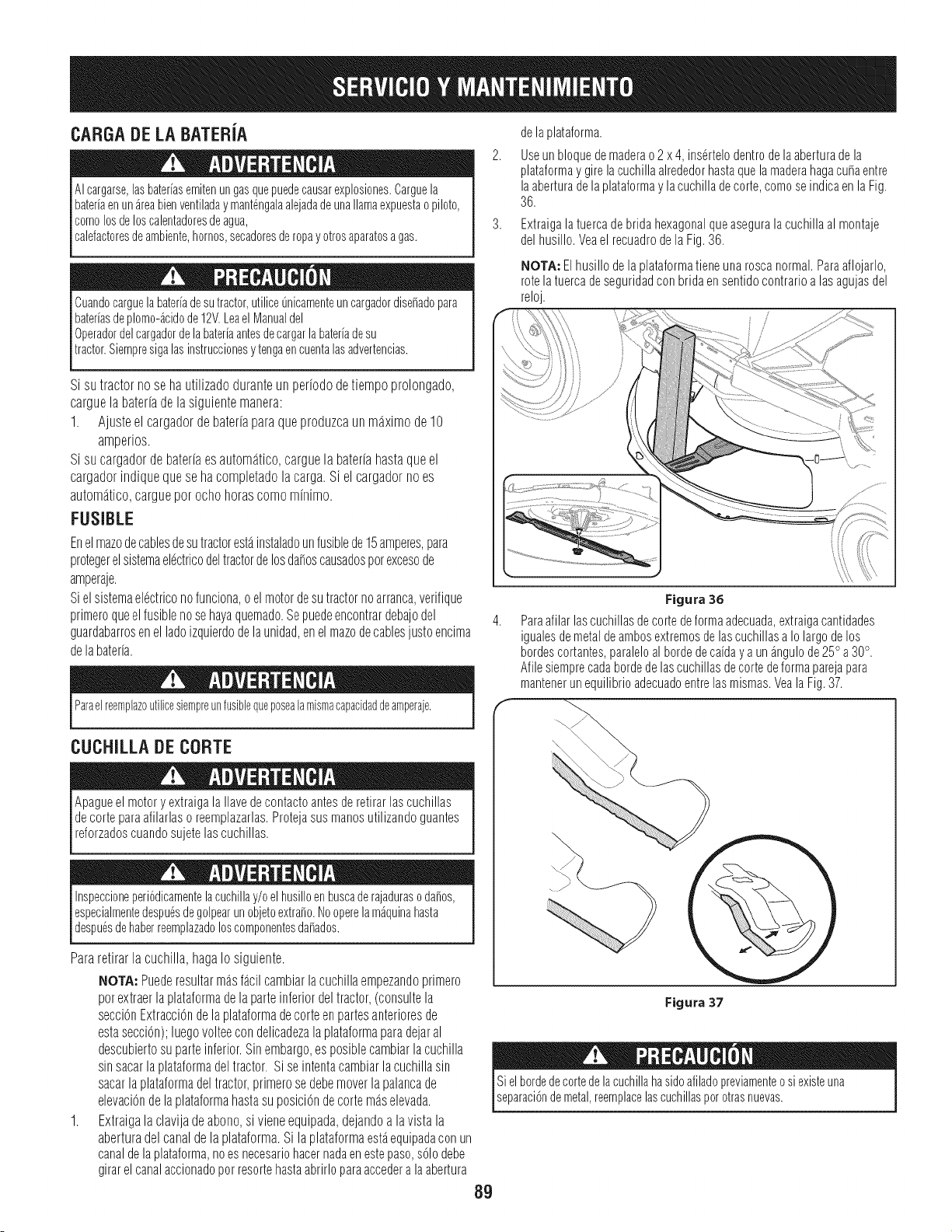
CARGADELABATERJA
AIcargarse,lasbateriasemitenungasquepuedecausarexplosiones.Carguela
bateriaenun_reabienventiladay mant@galaalejadade unallamaexpuestaopiloto,
comolosdeloscalentadoresdeagua,
calefactoresdeambiente,hornos,secadoresderopay otrosaparatosagas.
Cuandocarguelabateriadesutractor,utilice@icamenteuncargadordise_adopara
bateriasdeplomo@idode12V.Leael Manualdel
0peradordelcargadordelabateriaantesdecargarlabateriadesu
tractor.Siempresigalasinstruccionesy tengaencuentalasadvertencias.
Si su tractor no se ha utilizado duranteun periodo de tiempo prolongado,
carguela bateriade lasiguiente manera:
1. Ajusteel cargadorde bateriapara queproduzcaun maximode 10
amperios.
Si su cargadorde bateriaesautomatico,carguela bateriahastaque el
cargadorindique que se ha completadola carga.Si el cargadorno es
automatico,carguepor ocho horas como minimo.
FUSIBLE
Enel mazodecablesdesutractorest_instaladoun fusiblede15amperes,para
protegerelsistemaeldctricodeltractordelosda_oscausadospot excesode
amperaje.
Sielsistemael@tricono funciona,o elmotordesutractorno arranca,verifique
primeroqueelfusibleno sehayaquemado.Sepuedeencontrardebajodel
guardabarrosenel ladoizquierdodelaunidad,enel mazodecablesjusto encima
de labateria.
I ParaelreemplazoLltilicesiempreLlnfusibleqLleposealamismacapacidaddeamperaje. I
I
CUCHILLA DE CORTE
Apagueel motoryextraigala Ilavedecontactoantesde retirarlascuchillas
decorte paraafilarlaso reemplazarlas.Protejasus manosutilizandoguantes
reforzadoscuandosujetelascuchillas.
Inspeccioneperi6dicamentelacuchillay/o elhusilloenbuscade rajadurasoda_os,
especialmentedespu6sdegolpearunobjetoextra_o.Nooperelam_quinahasta
despu6sdehaberreemplazadoloscomponentesda_ados.
Para retirar la cuchilla, hagaIo siguiente.
NOTA: Puederesultarmasfacil cambiarlacuchillaempezandoprimero
potextraerla plataformade laparteinferiordel tractor,(consultela
secci6nExtracci6nde laplataformadecorteen partesanterioresde
estasecciOn);luegovolteecon delicadezalaplataformaparadejaral
descubiertosu parteinferior.Sinembargo,es posiblecambiarla cuchilla
sinsacarla plataformadeltractor. Sise intentacambiarla cuchillasin
sacarlaplataformadel tractor,primerose debemoverlapalancade
elevaciOndela plataformahastasu posiciOnde cortemaselevada.
1. Extraigala clavija de abono,si viene equipada,dejandoa la vista la
aberturadel canal de la plataforma.Si la plataformaestaequipadaconun
canaldela plataforma,noes necesariohacernadaen estepaso,s61odebe
girarel canalaccionadopor resortehastaabrirloparaaccedera laabertura
89
delaplataforma.
Useun bloquedemaderao2 x 4, ins_rtelodentrodelaaberturade la
plataformay girelacuchillaalrededorhastaquelamaderahagacu_aentre
laaberturade la plataformay lacuchilladecorte,comoseindicaen laFig.
36.
Extraigala tuercade brida hexagonalqueaseguralacuchillaal montaje
delhusillo. Veael recuadrode laFig.36.
NOTA: Elhusillo dela plataformatieneunaroscanormal.Paraaflojarlo,
rotela tuercade seguridadcon bridaen sentidocontrarioalas agujasdel
reloj.
i /
Figura 36
Paraafilar lascuchillasde cortedeformaadecuada,extraigacantidades
igualesde metaldeambosextremosde lascuchillasa Io largode los
bordescortantes,paraleloal bordedeca[day a unangulode25° a30°.
Afilesiemprecadabordede lascuchillasdecorte deformaparejapara
mantenerun equilibrioadecuadoentrelasmismas.Veala Fig.37.
\\
Figura 37
Sielbordedecortedela cuchillahasideafiladopreviamenteosi existeuna
separaci6ndemetal,reemplacelascuchillasperotrasnuevas.
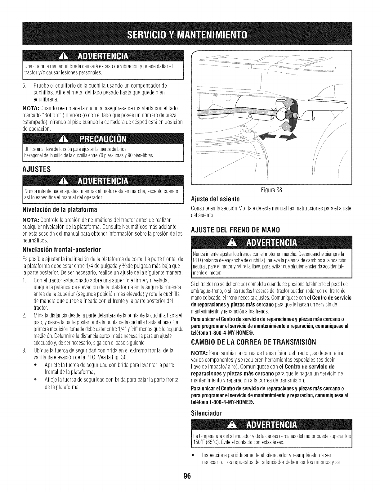
Unacuchillamalequilibradacausaraexcesodevibraci6nypuededa_arel
tractory/ocausarlesionespersonales.
5. Pruebeelequilibriodela cuchillausandoun compensadorde
cuchillas.Afileelmetaldelladopesadohastaquequedebien
equilibrada.
NOTA"Cuandoreemplacelacuchilla,asegLiresedeinstalarlaconel lado
marcado"Bottom"(inferior)(oconelladoqueposeeunmimerodepieza
estampado)mirandoal pisocuandolacortadoradec6spedestaenposici6n
deoperaci6n.
UtiliceunaIlavedetorsi6nparaajustarlatuercadebrida
hexagonaldelhusillodelacuchillaentre70pies-librasy 90 pies-libras.
AJUSTES
S .............................................
Nuncaintentehacerajustesmientrasel motorestaen marcha,exceptocuando
as[Io especificael manualdel operador.
Nivelaci6n de la plataforrna
NOTA: Controlelapresi0ndeneumaticosdeltractorantesderealizar
cualquiernivelaci6ndela plataforma.ConsulteNeumaticosmasadelante
enestasecci6ndelmanualparaobtenerinformaci6nsobrelapresi6nde los
neumaticos.
Nivelaci6n frontal-posterior
EsposibleajustarlainclinaciOnde laplataformade corte.Lapartefrontalde
laplataformadebeestarentre1/4 depulgaday3/sdepulgadamasbajaque
laparteposterior.Desernecesario,realiceunajustedela siguientemanera:
1. Conel tractorestacionadosobreunasuperficiefirmey nivelada,
ubiquelapalancadeelevaciOndela plataformaen lasegundamuesca
antesdelasuperior(segundaposiciOnmaselevada)y rotela cuchilla
demaneraquequedealineadaconelfrentey laparteposteriordel
tractor.
2. Midala distanciadesdelapartedelanteradelapuntadelacuchillahastael
piso,y desdelaparteposteriordelapuntadelacuchillahastaelpiso.La
primeramediciOntomadadebeestarentre1/4"y3/8"menosquelasegunda
mediciOn.Determineladistanciaaproximadanecesariaparaunajuste
adecuadoy,desernecesario,sigaconelpasosiguiente.
3. Ubiquelatuercadeseguridadconbridaenelextremofrontaldela
varilladeelevaciOndelaPTO.VealaFig.30.
o Aprietelatuercadeseguridadconbridaparalevantarlaparte
frontaldelaplataforma;
o Aflojelatuercadeseguridadconbridaparabajarlapartefrontal
delaplataforma.
Figura38
Ajuste del asiento
Consulteenlasecci6nMontajedeestemanuallasinstruccionesparaelajuste
delasiento.
AJUSTE DEL FRENO DE MANO
Nuncaintenteajustarlosfrenosconelmotorenmarcha.Desenganchesiemprela
PTO(palancadeenganchedecuchilla),muevalapalancadecambiosa laposici6n
neutral,pareel motory retirelaIlave,paraevitarquealguienenciendaaccidental-
menteelmotor.
Sieltractornosedetienepercompletecuandosepresionatotalmenteel pedalde
embrague-treno,o silasruedastraserasdeltractorpuedenrodarconelirenede
manecolocado,elfrenonecesitaajustes.Comuniqueseconel Centrodeservicio
dereparacionesy piezasm_scercanoparaquelehaganunserviciode
mantenimientoy reparaci6nalosfrenos.
PBrBubicarelCentrodeserviciodereparacionesy piezasm_scercanoo
paraprogramarelserviciodemantenimientoo reparaci6n,comuniqueseal
tel6fonoI=800=4-MY=tl0ME®.
CAMBiO DELA CORREADETRANSMISION
NOTA:Paracambiarlacorreadetransmisi6ndeltractor,sedebenretirar
varioscomponentesy serequierenherramientasespeciales(esdeck,
Ilavedeimpacto/aire).Comuniqueseconel Centrodeserviciode
reparacionesy piezasrn&scercanoparaquelehaganunserviciode
mantenimientoy reparaci6na lacorreadetransmisi6n.
ParaubicarelCentrodeserviciodereparacionesy piezasm_scercanoo
paraprogramarelserviciodemantenimientoy reparaci6n,comuniqueseal
tel6fono1-800-4-MY-HOME®.
Sileneiador
Latemperaturadelsilenciadory de las_reascercanasdelmotorpuedesuperarlos
150°F(65°0). Eviteel contactoconestas_reas.
,, InspeccioneperiOdicamenteelsilenciadory reemplacelodeser
necesario.Losrepuestosdelsilenciadordebenserlosmismosy se
96
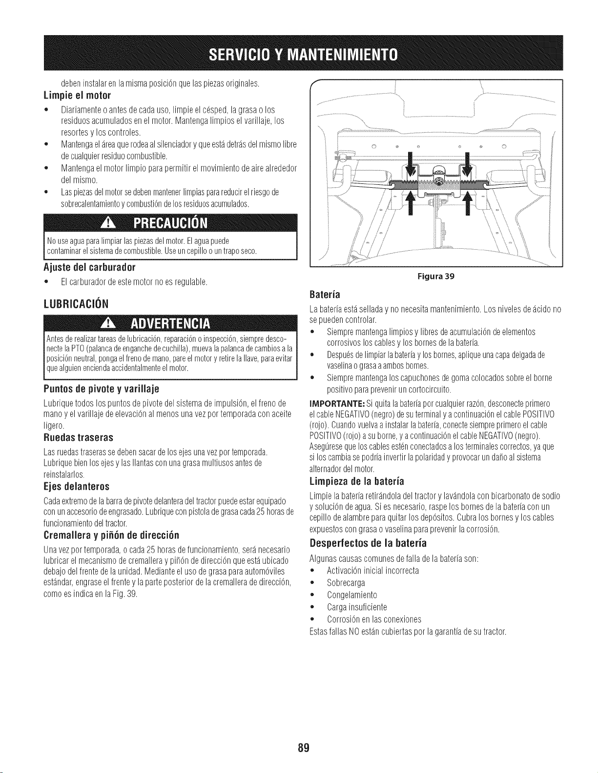
@beninstalarenlamismaposiciOnquelaspiezasoriginales.
Lirnpie el motor
= Diariamenteo antesdecadauso,limpieel@sped,lagrasao los
residuosacumuladosenelmotor.Mantengalimpioselvarillaje,los
resortesy loscontroles.
,, Mantengaelareaquerodeaalsilenciadory queestadetrasdelmismolibre
decualquierresiduocombustible.
,, Mantengaelmotorlimpioparapermitirelmovimientodeairealrededor
delmismo.
,, Laspiezasdelmotorsedebenmantenerlimpiasparareducirel riesgode
sobrecalentamientoycombustiondelosresiduesacumulados.
Nouseaguaparalimpiarlaspiezasdelmotor.El aguapuede
contaminarel sistemadecombustible.Useuncepilloountraposeco.
Ajuste del carburador
,, Elcarburadordeestemotornoesregulable.
LUBRICACION
AntesderealizartareasdelubricaciOn,reparaciOnoinspecciOn,siempredesco-
nectelaPTO(palancadeenganchedecuchilla),muevalapalancadecambiosa la
posiciOnneutral,pongaelfrenodemane,pareelmotory retirelaIlave,paraevitar
queaguenencendaaccdentamentee motor.
Puntos de pivote y varillaje
Lubriquetodoslospuntosde pivotedelsistemadeimpulsion,elfrenode
manoy el varillajedeelevaci0nalmenosunavezportemporadaconaceite
ligero.
Ruedas traseras
Lasruedastraserassedebensacardelosejesunavezportemporada.
Lubriquebienlosejesy lasIlantasconunagrasamultiusosantesde
reinstalarlos.
Ejes delanteros
Cadaextremodelabarradepivotedelanteradeltractorpuedeestarequipado
conunaccesoriodeengrasado.Lubriqueconpistoladegrasacada25horasde
funcionamientodeltractor.
Crernallera y pifi6n de direcci6n
Unavezportemporada,ocada25horasdefuncionamiento,seranecesario
lubricarel mecanismodecremalleray pi_OndedirecciOnqueestaubicado
debajodelfrentede launidad.MedianteelusodegrasaparaautomOviles
estandar,engraseelfrentey la parteposteriordela cremalleradedirecciOn,
comoesindicaenlaFig.39.
\
Figura 39
Bateria
Labateriaestaselladay nonecesitamantenimiento.Losnivelesdeacidono
sepuedencontrolar.
,, Siempremantengalimpiosy libresdeacumulaciOndeelementos
corrosivosloscablesy losbornesdelabateria.
,, Despu_sdelimpiarlabateriaylosbornes,apliqueunacapadelgadade
vaselinaograsaaambosbornes.
,, Siempremantengaloscapuchonesdegomacolocadossobreel borne
positivoparapreveniruncortocircuito.
IMPORTANTE:Siquitalabateriaporcualquierraz0n,desconecteprimero
elcableNEGATIVO(negro)desuterminaly acontinuaci0nelcablePOSITIVO
(rojo).Cuandovuelvaa instalarlabateria,conectesiempreprimeroelcable
POSITIVO(rojo)asuborne,y acontinuaci0nelcableNEGATIVO(negro).
Aseguresequeloscablesest@conectadosa losterminalescorrectos,yaque
si loscambiasepodriainvertirlapolaridady provocarunda_oalsistema
alternadordelmotor.
Lirnpieza de la bateria
Limpielabateriaretirandoladeltractory lavandolaconbicarbonatodesodio
y soluciOndeagua.Siesnecesario,raspelosbornesdelabateriaconun
cepillodealambreparaquitarlosdepOsitos.Cubralosbornesy loscables
expuestoscongrasaovaselinaparaprevenirlacorrosion.
Desperfectosde la bateria
Algunascausascomunesdefalladelabateriason:
,, Activaci0ninicialincorrecta
,, Sobrecarga
,, Congelamiento
,, Cargainsuficiente
,, CorrosiOnenlasconexiones
EstasfallasNOestancubiertasporlagarantiadesutractor.
89
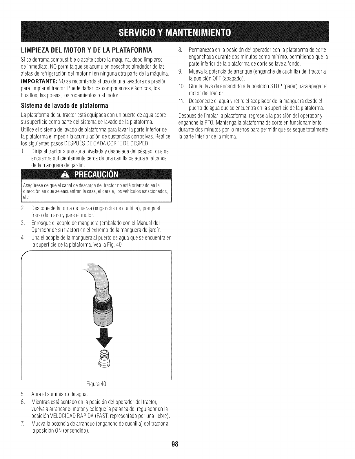
LliVIPIEZADELMOTORY DELA PLATAFORiVlA
Sise derramacombustibleoaceitesobrela m_quina,debelimpiarse
deinmediato.NOpermitaqueseacumulendesechosalrededordelas
aletasderefrigeraciOndel motorni en ningunaotra partedela m_quina.
INIPORTANTE:NOse recomiendael usodeunalavadorade presiOn
paralimpiarel tractor.Puededa_arlos componentesel6ctricos,los
husillos,laspoleas,los rodamientoso el motor.
Sistema de lavado de plataforma
Laplataformadesu tractorest_equipadaconun puertode aguasobre
su superficiecomopartedel sistemade lavadode la plataforma.
Utiliceel sistemadelavadodeplataformaparalavarlaparteinferiorde
la plataformae impedirla acumulaci0ndesustanciascorrosivas.Realice
los siguientespasosDESPUESDECADACORTEDECESPED:
1. Dirijaeltractora unazonaniveladay despejadadelc6sped,quese
encuentresuficientementecercade unacanilladeaguaal alcance
dela mangueradeljardn.
8. Permanezcaenla posici6ndeloperadorconlaplataformade corte
enganchadadurantedosminutoscomominimo,permitiendoquela
parteinferiordela plataformadecortese laveafondo.
9. Muevala potenciadearranque(enganchede cuchilla)deltractora
laposici0nOFF(apagado).
10. Girela Ilavedeencendidoa laposiciOnSTOP(parar)paraapagarel
motordeltractor.
11. Desconecteel aguay retireel acopladorde lamangueradesdeel
puertodeaguaqueseencuentraenla superficiedela plataforma.
Despu6sdelimpiarla plataforma,regresea la posici0ndeloperadory
enganchela PTO.Mantengalaplataformadecorte enfuncionamiento
durantedos minutospor Io menosparapermitirque sesequetotalmente
laparteinferiordelamisma.
Aseg0resedequeel canalde descargadel tractorno est_orientadoen la
direcci6nenqueseencuentranlacasa,elgaraje,losveh[culosestacionados,
etc.
2. Desconectelatomadefuerza(enganchedecuchilla),pongael
frenodemanoy pareel motor.
3. Enrosqueelacopledemanguera(embaladoconel Manualdel
Operadordesutractor)enel extremode la mangueradejardh.
4. Unael acoplede la mangueraalpuertodeaguaqueseencuentraen
lasuperficiedela plataforma.VealaFig.40.
Figura40
5. Abrael suministrodeagua.
6. Mientrasest_sentadoenla posiciOndeloperadordeltractor,
vuelvaaarrancarel motory coloquelapalancadel reguladorenla
posici0nVELOCIDADRAPIDA(FAST,representadoporuna liebre).
7. Muevala potenciadearranque(enganchedecuchilla)deltractora
la posici0nON(encendido).
98
Nuncaalrnacenetractorde c_spedcon combustibleen el tanqueen un espaciocerradoo en _.reascon pocaventilad6n,dondelos gasesdel
combustiblepuedanalcanzarel fuego,chispaso una luz pilotocornola que fienenalgunoshornos,calentadoresde agua,secadoresde ropa
oalgOnotrodispositivoa gas.
PREPARACION DEL MOTOR
IMPORTANTE:Elcombustiblequequedaen el tanquecuandohace
calorse deterioray ocasionagravesproblernasde encendido.
La noutilizaci6nde un aditivode combustibledeestabilizaci6no
totalrnenteenrnarchael motorhastaque sequedansincombustible
antesde su alrnacenarnientofueradeternporadapuederesultar
enda_osal carburadordel motor.Da_osposterioresnoestarian
cubiertospor lagaranfiadel fabricante.
Motoresse alrnacenaentre30y 90 dias debensertratadoscon un
estabilizadorde gasolinay los rnotoresalrnacenadosrn_.sde90 dias
es necesariodrenarel combustibleparaevitarel deterioroy la gorna
de laforrnaci6nenel sisternade combustibleoen las partesesen-
cialesdel carburador.Si la gasolinaen el motorse deterioradurante
elalrnacenarniento,puedeser necesariotenetel carburador,y otros
cornponentesdelsisternadecombustible,la reparaci6no sustituci6n.
Paraevitarque se forrnendep6sitosde gornaenel interiordel
carburadordel motory causarun posiblernal funcionarnientodel mo-
tor,el sisternadecombustibledebe servaciadocornpletarnente,o la
gasolinadebesertratadocon un estabilizadorpara evitarsu deterioro.
1. Si utilizaun estabilizadordecombustible:
a. Lea las instruccionesy recornendacionesdelfabricantedel
producto.
b. Agreguela cantidadcorrectadeestabilizadorparala
capacidaddel sisternade combustiblea gasolinalirnpiay
nueva.
c. Lleneel dep6sitode combustibleconcombustibletratado
y haga funcionarel motor2-3rninutosparaestabilizarel
combustibledentrodelcarburador.
2. Cuandovacie el sisternade combustible:
a. Nodreneel combustiblecuandoel motorest,. caliente.
Perrnitaqueel motorse enfrie bien.Dreneel combustible
dentrode un recipienteaprobadoy al airelibre,lejosde
cualquierllamaexpuesta.
b. Dreneungran volurnende combustibledesdeel dep6sito,
desconectandolaIfneade combustibledel filtrode combus-
tibleen lineaquese encuentracercadel motor.
Lagasolinaessumamenteinflamabley puedesetexplosivaenciertas
condiciones.Vacielaantesdeaimacenarei equipoduranteperiodos
prolongados.Dreneel combustibleOnicarnentedentrodeun
recipienteaprobadoy al aire libre,lejosdecualquierllamaexpuesta.
Dejequeel motorseenfrie.Antesde drenarel combustible,apague
cigarrillos,cigarros,pipasy otrasfuentesde cornbusti6n.Vaciela
gasolinaenuna.reabienventilada,lejosdecualquierfuentedellama
o chispas,incluidocuaiquierartefactoconluzpiloto.AImacenela
gasolinaenunrecipienteaprobado,en unlugarseguro.
Vuelvaa contectarla Ifneade combustibley hagafuncionar
el motorhastaquecorniencea fallar,useentoncesel
cebadorpararnantenerel motorenrnarchahasta agotar
todoel combustibledel carburador.
d. Vuelvaa desconectarla linea de combustibley drene la
gasolinarestanteenel sisterna.
La gasolina es una sustancia t6xica. Elimine ia gasolina
adecuadamente. Comuniquese con las autoridades locales para
averiguar cua.iesson los metodos adecuados para eliminar la gasolina.
3. Extraigalabujiay viertauna(1)onzade aceitepara motorpot el
orificiode labujia en el cilindro.Hagagirarel motor variasveces
paradistribuirel aceite.Vuelvaa colocarla bujia.
4. Lirnpielos residuosdetodo motor,conprotecci6nparalosdedos,
y debajo,alrededory detr_.sdel silenciador.Retocarlapintura
da_ada,y las _.reasotropelaje quepuedenoxidarsecon una
peliculadelgadadeaceite.
5. Conservaren unlugar lirnpio,secoy bien ventiladolejosde
cualquieraparatoque funcionacon unallamao luz piloto,corno
unhomo,calentadorde aguao secadorade ropa.Tarnbi_nevitar
cualquier_.reacon un motorel_ctricoque produzcachispas,o
dondelas herrarnientasel_ctricassonoperados.
6. Sies posible,evitarlaszonasde almacenarnientoconalta
hurnedad,yaque prornuevela oxidaci6ny la corrosi6n.
7. Mantenerel nivelde motorde alrnacenarniento.Inclinaci6npuede
provocarfugasde aceiteo combustible.
EL DRENAJE DE LOS COMBUSTIBLES
1. Localiceel filtrodecombustible,que seencuentraen el lado
izquierdodel motor,y puede serconectadoal motorcon una
correade ernpate.
2. Cortarla correade la corbata,si est,.presente,entonceserner-
genteen la abrazaderaen linea en elfiltrode combustiblecon un
pardealicates,deslicela abrazaderade la linea de combustible.
3. QuitelaIfneade combustibleen la lineay lafuga decombustible
en un recipienteaprobado.
PREPARACION DE LA TRACTOR DE CI=SPED
1. Lirnpiey lubriquela tractorcornosedescribeen lasinstrucciones
de lubricaci6n.
2. No utiliceunalavadoraa presi6nni unarnangueradejardin para
lirnpiarsu unidad.
3. Alrnacenela tractoren unazona lirnpiay seca.No la alrnacene
cercade rnaterialescorrosivoscornopor ejernplofertilizantes.
ELIMINACION DE ALMACENAMIENTO
1. Revisesu motorcornose describeen la secci6nde la Asarnblea
de estemanual.
2. Siel combustibleruedrenadodurantela preparaci6ndealrnace-
narniento,Ileneeltanquecon gasolinafresca.Si ustedrnantiene
uncontenedorde gasolinapararepostar,asegQresede que
contienes61ocombustiblefresco.La gasolinase oxiday deteriora
con el tiernpo,causandoproblernasde arranque.
3. Siel cilindrorue recubiertaconaceite durantela preparaci6nde
alrnacenarniento,el motorde hurnoal arrancar.Estoes normal.
99
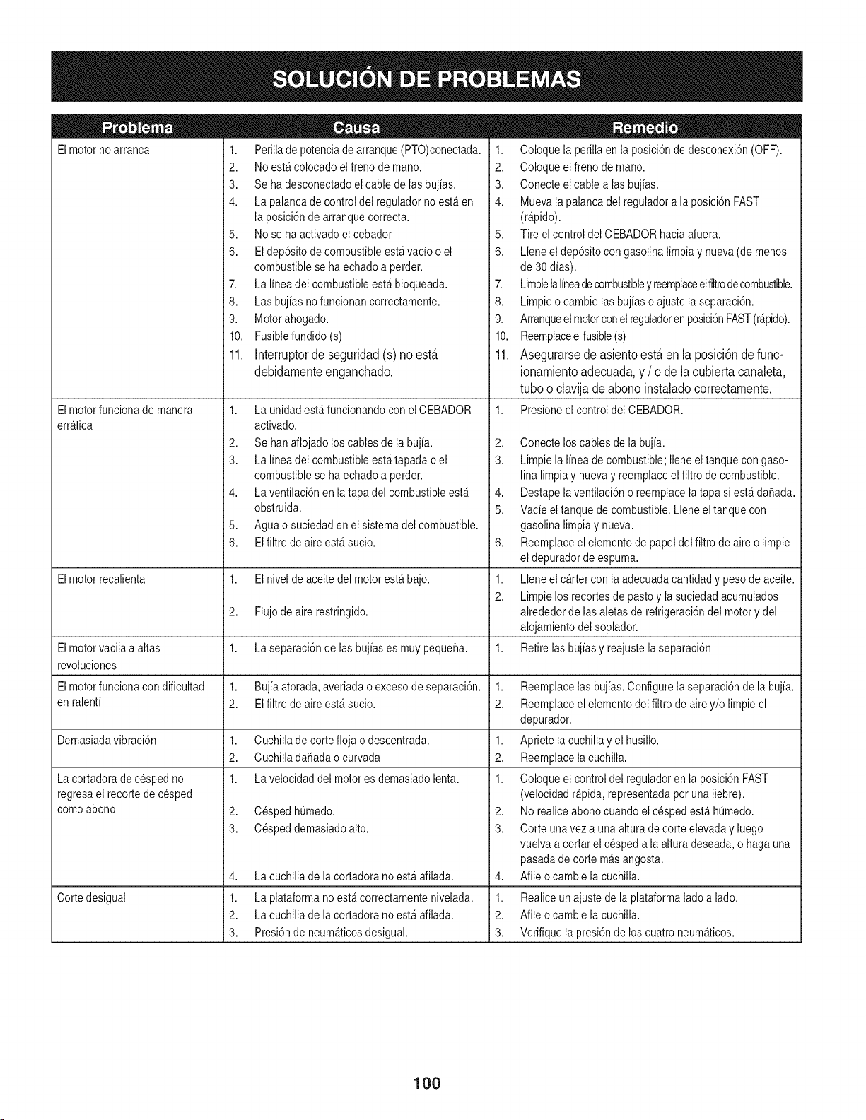
Elmotorno arranca
Elmotorfuncionade manera
err_tica
1. Perillade potenciade arranque(PTO)conectada.
2. Noest&colocado elfreno de mano.
3. Se ha desconectadoel cablede lasbujias.
4. La palancade controldel reguladorno est_en
la posici6nde arranquecorrecta.
5. Nose ha activadoel cebador
6. El dep6sitode combustibleest_vacio o el
combustiblese ha echadoa perder.
7. La linea del combustibleest&bloqueada.
8. Las bujias nofuncionan correctamente.
9. Motorahogado.
10. Fusiblefundido(s)
11. Interruptor de seguridad (s) no est,.
debidarnente enganchado.
1. La unidad est_ funcionandocon el CEBADOR
activado.
2. Se hanaflojadoloscables de la bujia.
3. La linea del combustibleest_tapada o el
combustiblese ha echadoa perder.
4. La ventilaci6nen la tapadel combustibleest_
obstruida.
5. Aguao suciedaden el sistemadel combustible.
6. EIfiltro de aireest_ sucio.
1. Coloque la perillaen la posici6nde desconexi6n(OFF).
2. Coloque elfreno de mano.
3. Conecte elcable alas bujias.
4. Muevala palancadel reguladora la posici6nFAST
(r@ido).
5. Tire elcontrol del CEBADORhaciaafuera.
6. Lleneel dep6sitocon gasolina limpiay nueva(de menos
de 30dias).
7. Limpielalineadecombustibley reemplaceelfiltrodecombustible.
8. Limpieo cambie lasbujias o ajustela separaci6n.
9. Arranqueelmotorconelreguladoren posici6nFAST(r&pido).
10. Reemplaceelfusible(s)
11. Asegurarse de asiento est,. en la posici6n de func-
ionarniento adecuada, y / o de la cubierta canaleta,
tubo o clavija de abono instalado correctamente.
1. Presioneel control del CEBADOR.
2,
3.
4,
5.
6,
Elmotorrecalienta 1. El nivel de aceitedel motorest_ bajo. 1.
2.
2. Flujodeairerestringido.
Elmotorvacila a altas 1. La separaci6nde lasbujias es muypequeSa. 1.
revoluciones
Elmotorfuncionacon dificultad 1. Bujiaatorada,averiadao excesode separaci6n. 1.
en ralenti 2. El filtrode aireest_ sucio. 2.
Demasiadavibraci6n 1. Cuchillade cortefloja o descentrada. 1.
2. CuchilladaSadaocurvada 2.
1. La velocidaddel motores demasiadolenta. 1.
2. CespedhQmedo.
La cortadorade cespedno
regresael recortede cesped
comoabono
Cortedesigual
3. Cespeddemasiadoalto.
La cuchillade lacortadora no est_afilada.
La plataformano est&correctamentenivelada.
La cuchillade lacortadora no est_afilada.
Presi6nde neum_ticosdesigual.
4,
1.
2.
3.
Conecte loscables de la bujia.
Limpiela linea de combustible;Ileneeltanquecon gaso-
lina limpiay nuevay reemplaceelfiltro decombustible.
Destapelaventilaci6no reemplacela tapa si est_ da_ada.
Vacie el tanquede combustible.Lleneel tanquecon
gasolina limpiay nueva.
Reemplaceelelementode papeldel filtro de aireo limpie
el depuradorde espuma.
Lleneel c&rtercon laadecuadacantidady pesode aceite.
Limpielos recortesde pastoy la suciedadacumulados
alrededorde lasaletasde refrigeraci6ndel motory del
alojamientodel soplador.
Retirelasbujias y reajustelaseparaci6n
Reemplacelas bujias.Configurela separaci6nde la bujia.
Reemplaceelelementodel filtro deairey/o limpie el
depurador.
Apriete lacuchillay el husillo.
Reemplacelacuchilla.
Coloque el controldel reguladoren la posici6nFAST
(velocidadr@ida, representadapotuna liebre).
2. Norealiceabonocuandoel cespedest&hQmedo.
3. Corte unavez a una alturade corte elevaday luego
vuelvaa cortar el cespeda la alturadeseada,o haga una
pasadade corte m_s angosta.
4. Afile ocambie la cuchilla.
1. Realiceun ajustede laplataformalado a lado.
2. Afile ocambie la cuchilla.
3. Verifiquela presi6nde los cuatro neum_ticos.
1OO

Esta pagina se dej6 intencionalmente en blanco. Utilice esta pagina para tomar notas acerca de su tractor.
101

Esta pagina se dej6 intencionalmente en blanco. Utilice esta pagina para tomar notas acerca de su tractor.
102
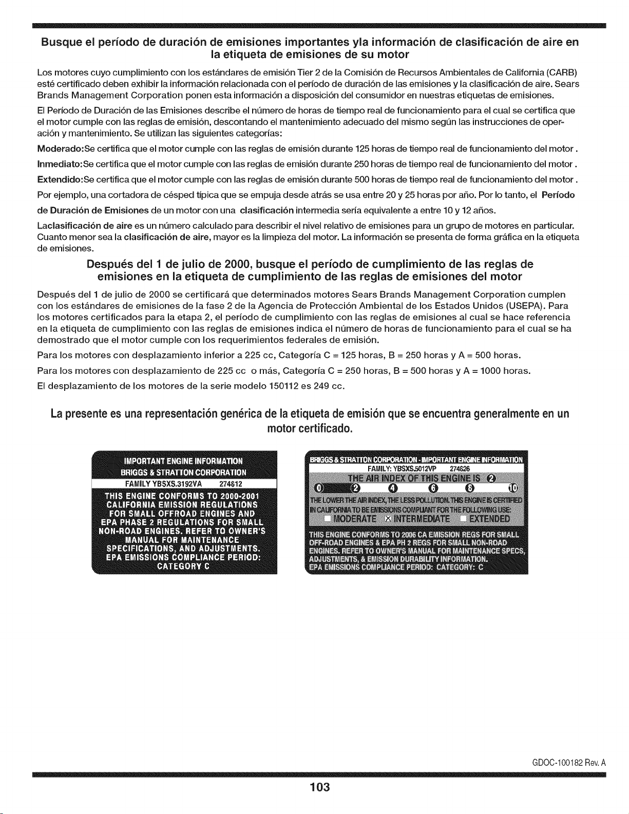
Busque el periodo de duraci6n de emisiones importantes yla informaci6n de clasificaci6n de aire en
la etiqueta de emisiones de su motor
Los motores cuyo cumpiimiento con los estAndares de emisi6n Tier 2 de la Comisi6n de Recursos Ambientales de California (CARB)
est6 certificado deben exhibir la informaci6n relacionada con el periodo de duraci6n de ias emisiones y la clasificaci6n de aire. Sears
Brands Management Corporation ponen esta informaci6n a disposici6n del consumidor en nuestras etiquetas de emisiones.
Ei Periodo de Duraci6n de las Emisiones describe el nQmero de horas de tiempo real de funcionamiento para el cuai se certifica que
el motor cumpie con ias reglas de emisi6n, descontando el mantenimiento adecuado del mismo segQn las instrucciones de oper-
aci6n y mantenimiento. Se utilizan las siguientes categonas:
Moderado:Se certifica que el motor cumpie con las reglas de emisi6n durante 125 horas de tiempo real de funcionamiento del motor.
Inmediato:Se certifica que el motor cumpie con las reglas de emisi6n durante 250 horas de tiempo real de funcionamiento del motor.
Extendido:Se certifica que el motor cumpie con las reglas de emisi6n durante 500 horas de tiempo real de funcionamiento del motor.
Por ejemplo, una cortadora de c6sped tJpica que se empuja desde arras se usa entre 20 y 25 horas por aSo. Por Io tanto, el Periodo
de Duraci6n de Emisiones de un motor con una clasificaci6n intermedia sena equivaiente a entre 10 y 12 aSos.
Laciasificaci6n de aire es un nQmero calculado para describir el nivel relativo de emisiones para un grupo de motores en particular.
Cuanto menor sea la clasificaci6n de aire, mayor es la limpieza del motor. La informaci6n se presenta de forma grAfica en la etiqueta
de emisiones.
Despu_s del 1 de julio de 2000, busque el periodo de cumplimiento de las reglas de
emisiones en la etiqueta de cumplimiento de las reglas de emisiones del motor
Despu6s del 1 de julio de 2000 se certificarA que determinados motores Sears Brands Management Corporation cumplen
con los estAndares de emisiones de la fase 2 de la Agencia de Protecci6n Ambientai de los Estados Unidos (USEPA). Para
los motores certificados para la etapa 2, el periodo de cumplimiento con ias reglas de emisiones al cual se hace referencia
en la etiqueta de cumplimiento con las reglas de emisiones indica el nQmero de horas de funcionamiento para el cual se ha
demostrado que el motor cumple con los requerimientos federales de emisi6n.
Para los motores con desplazamiento inferior a 225 cc, Categoria C = 125 horas, B = 250 horas y A = 500 horas.
Para los motores con desplazamiento de 225 cc o mAs, Categoria C = 250 horas, B = 500 horas y A = 1000 horas.
El desplazamiento de los motores de la serie modelo 150112 es 249 cc.
La presente es una representaci6n gen_rica de la etiqueta de emisi6n que se encuentra generaimente en un
motor certificado.
FAMILYYBSXS.3192VA 274812
GDOC-100182Rev.A
103
(Esta p_.ginase aplica s61oen EE.UU. y Canada.).
Sears Brands Management Corporation, el Consejo de Recursos Ambientales de California (CARB)
y la Agencia de Protecci6n Ambiental de los Estados Unidos (EPA)
Declaraci6n de garantia del sistema de control de emisiones (derechos y obligaciones de la garanfia de defectos del propi=
etario)
LA COBERTURADE LA GARANTJADE CONTROLDEEMISIONESES Y PARALOSMODELOSCERTIFICADOSDELANO 1997Y POSTERIORES,
APLIOABLEA LOS MOTORESCERTIFICADOSCOMPRADOSENCALIFOR- QUESE COMPRENY UTILICENEN CUALQUIERPARTEDE LOSESTADOS
NIA EN1995Y POSTERIORMENTE,QUESE UTILIZANENCALIFORNIA, UNIDOS(Y A PARTIRDEL 1 DE ENERODE2001 ENCANADA).
Declaraci6n de garanfia sobre defectos en el control de emisiones para California y los Estados Unidos
ElConsejode RecursosAmbientalesde California(CARB),la EPA(Agencia
de Protecci6nAmbientalde los EE.UU.)y Searstienenel gusto de explicarla
garantiadel sistemade control de emisionespara motoresdela_o 2000y para
elfuturo con relaci6na motorespeque_ostodo terreno(SORE).En California,
los nuevosmotorespeque_ostodo terrenodebenestar dise_ados,construidos
y equipadosparacumplircon las rigurosasnormasanti-smogdelestado.En
el restode los EstadosUnidos,losmotoresnuevostodoterrenode encendido
porchispacertificadosparael a_o 1997debencumplirest_ndaressimilares
establecidospot la EPA.Sears debegarantizarel sistemade control de emis-
ionesde su motorparalosperiodosde tiempoenumeradosa continuaci6n,
siemprequeno hayaabuso,negligenciao mantenimientoindebidode su
motortodoterrenopeque_o.Su sistemade controldeemisionespuedeincluir
piezastalescomoel carburador,el filtro de aire, elsistemade encendido,el
silenciadoryel conversorcatalitico.Tambienpuedeincluirconectoresy otras
unidadesrelacionadascon las emisiones.Dondeexistaunacondici6ncubierta
por la garantia,Searsreparar_su peque6omotortodo terrenosin costo alguno
incluyendodiagn6stico,piezasy manodeobra
Cobertura de la garantJa Sears para defectos en el control de emJsiones
Los motorestodo terrenopeque6osest_ngarantizadosen Io relativoalcontrol alas disposicionesque se indiquena continuaci6n.Si una partede su motor
de emisionesparadefectosenpiezasduranteun periodode dos a_os,sujeto cubiertapot la garanfiaes defectuosa,Sears reparar_o sustituir_dichaparte.
Responsabilidades del propietario en relacibn con la garantia
Comopropietariodel motortodo terrenopeque_o,Ud.es responsablede la
realizaci6ndel mantenimientorequeridoquese incluyeen las instrucciones
de operaci6ny mantenimiento.Searsrecomiendaquese conserventodoslos
recibosrelativosal mantenimientode su motortodoterrenopeque_o,pero
no pude denegarla garantiasimplementepor la faltade los mismos,o por su
incumplimientodel mantenimientoprogramatic.Comopropietariodel motor
peque_otodoterrenodebe saberque, sinembargo,Searsle puedenegar
lacoberturade lagarantiasi su motortodoterrenopeque6oo una piezadel
mismohanfalladodebidoa abuso,negligencia,mantenimientoindebidoo
a modificacionesno aprobadas.Ud.es responsablede presentarsu motor
todoterrenopeque6oa un distribuidorde serviciosSearsautorizadotan pronto
comoaparezcaun problema.Las reparacionesde la garantiasinconfiicto
debencompletarseen un plazode tiempo razonable,no superiora 30 dias.Si
tienealgunapreguntarespectoa sus derechosy responsabilidadesreferen-
tes a la garantia,debe contactarcon un representantede serviciosSearsal
1--800--469--4663.La garantiade emisioneses unagarantiapor defectos.Los
defectosse juzgande acuerdocon elfuncionamientonormalde un motor.La
garantiano est_relacionadacon unapruebade emisionesen uso.
Disposiciones de la garantJa Sears para defectos en el control de emJsiones
Las siguientesson disposicionesespecificasrelacionadascon la coberturade lagarantia paradefectosen el controlde emisiones.Esun a_adidoa lagarantiade
motorSearsparamotoresno reguladosque seencuentraen lasinstruccionesde funcionamientoy mantenimiento.
1. Piezascon garantia
La coberturade esta garantiase extiendeL]nicamentealas piezas
queaparecena continuaci6n(las partesde lossistemasde controlde
emisiones),siempreque dichas piezasestuvieranya en el motoren el
momentode su compra.
a. Sistemade medici6n de combustible
• Sistema de enriquecimientopara arranqueen frio
• Carburadory partesinternas
• Bombade combustible
b. Sistemade inducci6nde aire
• Filtrode aire
• Colector de admisi6n
c. Sistemadeencendido
• Bujia(s)de encendido
• Sistema de encendidomagneto
d. Sistemadelcatalizador
• Convertidorcatalitico
• Colector de escape
• Sistema de inyecci6nde aireo v_lvulade impulsos
e. Elementosvariadosusadosen los sistemasanteriores
• Wlvulas de vacio,sensiblesa temperatura,posici6ny tiempo
e interruptores
• Conectoresy montajes
2. AIcancede la cobertura
Searsgarantizaal poseedorinicialy a loscompradoressubsiguientes
quelas piezascon garantiano tendr_n defectosen materialesni mano
de obra que provoquenla falla de las mismasduranteun periodode
dos aSosa partirde la fechaen queel motorse entregaa un comprador
particular.
3. Sin cargo
La reparaci6no reemplazodecualquierpartecon garantia se realizar_
sin cargo alguno parael poseedor,incluyendotareasde diagn6sticoque
permitandeterminarsi una partecon garantiaes defectuosa,siempreque
dichodiagn6sticose realiceen un distribuidor de serviciosSearsautoriza-
do. Parael serviciode lagarantia de emisiones,contacteal distribuidorde
serviciosSearsautorizadom_s cercanoincluidoen las"P_ginasamarillas"
en lascategorias"Motores,gasolina","Motoresde gasolina","Podadoras
de cesped",o similares.
4. Reclamacionesy exclusionesa la cobertura
Las reclamacionesde lagarantia debenenviarsede acuerdocon las
disposicionesde la politica de garantia para motoresSears.La cobertura
de lagarantia excluir_defectosen piezascongarantia queno scan partes
originalesSears,o abuso,negligenciao mantenimientoincorrecto,tal y
como se estableceen la politica de garantia paramotoresSears.Searsno
es responsablede lasfallas en piezascon garantia provocadaspor el uso
de partesa6adidas,que no scan originaleso quese hayan modificado.
5. Mantenimiento
Cualquierpartecon garantiaque no esteprogramadaparaser reem-
plazadacomomantenimientorequerido,o que s61odebainspeccionarse
regularmentealefecto de "inspeccioneo reemplacesegL]nsea necesario",
estar_garantizadacontradefectosduranteel periodode la garantia.Todas
las piezasgarantizadasqueesten programadaspara su reemplazopara
cumplir con los requisitosde mantenimientoestar_ngarantizadass61o
por el periodoanterior al primerreemplazoprogramaticparadicha pieza.
Cualquierpiezade recambioquesea equivalenteen funcionamientoy
durabilidadpuedeusarsepara realizarmantenimientoo reparaciones.El
propietarioes responsablede realizartodoel mantenimientorequerido,tal
y comose define en las instruccionesde funcionamientoy mantenimiento
Sears
6. Coberturaindirecta
Porla presente,la coberturase extiendea la falla de cualquiercomponente
de motorprovocadapot lafalla de unapiezacon garantiaque estetodavia
en periodode garantia.
En los EstadosUnidosy Canad_hay unalinea de atenci6nde 24 horas,1-800-469--4GG3,quecuentacon un menL]con mensajespre-grabadosque contienen
informaci6npara el mantenimientode motores.
DECLARACIONFEDERALy/oDECALIFORNIASOBRE GARANTJAS EN EL CONTROL DE EIVIISIONES
SUS DERECHOS Y OBLIGACIONES EN CUANTO A LA GARANTJA
MTDConsumerGroupInc, laAgencia de Protecci6nMedioambientalde los EstadosUnidos(EPA),y paraaquellosproductoscertificadosparasu ventaen el es-
tadode California,el Departamentode los Recursosdel Aire de California(CARB)secomplacenen explicarla garanfiaque cubreal sistemade control(ECS)de
emisiones(evaporativasy/o de escape)de su equipoy motor(motor de equipos de exteriores)de encendidopot chispa paratodo terreno,peque_o,de exteriores
del a_o2006 y a_osposterioresEn California,losnuevosmotoresde equipos de exterioresdebenestar dise_ados,construidosy equipadospara cumplircon las
estrictasnormasantipoluci6ndel Estado(en otrosestados,losequipos del a_o 1997y modelosposterioresdebenserestar dise_ados,construidosy equipados
para cumplircon las regulacionesde motoresde encendidopor chispapara todoterrenopeque_osde laAgencia de Protecci6nMedioambientalde los Estados
Unidos,(EPA).MTDConsumerGroupInc. debe garantizarel sistemade control de emisiones(ECS) de su motorde equipos de exteriorespot el periodode
tiempo indicadom_sabajo,siemprey cuando noexistauso incorrecto,negligenciao mantenimientoinadecuadode dicho motor.
Su ECSpuedeincluir piezastales como el carburador,el sistemade inyecci6nde combustible,el sistemade encendido,el convertidorcatalitico,losdep6sitos
de combustible,laslineas de combustible,lostaponesde combustible,las v_lvulas,contenedores,filtros, manguerasde vapor,abrazaderas,conectoresy otros
componentesafinesrelacionadosconlasemisiones.
Dondeexista unacondici6ncubiertapor la garantia,MTDConsumerGroupInc. reparar_su motorde equiposde exterioressincostoalguno incluyendoel
diagn6stico,las piezasy la mano de obra.
COBERTURA DE LA GARANTJA DEL FABRICANTE:
Este sistemade control de emisionesse garantizaporel t@minode dos aSos.Si algunapieza relacionadacon lasemisionesde su motorde equiposde
exterioreses defectuosa,MTDCONSUMERGROUPINC. reparar_o sustituir_dichapieza.
RESPONSABILIDADES DEL PROPIETARIO SEGUN LA GARANTJA:
En su car_cterde propietariodel motorde equipos de exteriores,usted es responsabledel mantenimientorequeridoquese especificaen el manualdel propieta-
rio.MTDConsumerGroupInc le recomiendaque conservetodos losrecibos quecubrenel mantenimientode su motor,no obstanteIo cual MTDConsumerGroup
Inc no podr_denegarel cumplimientode lagarantia Qnicamentepor lafaltade los recibos.
Comopropietariodel motorde equiposde exteriores,usteddebe saber queMTDConsumerGroupInc. puededenegarlacoberturade lagarantia si su motoro
unapiezadel mismofallan debido a uso incorrecto,negligencia,mantenimientoindebidoo a modificacionesno aprobadas.
Ustedes responsablede presentarsu motoral centrode distribuci6no serviciotecnico de MTDConsumerGroupInc. tan prontocomo aparezcael problema.Las
reparacionescubiertaspor la garantiase debenIlevara caboen unlapso razonableque no excedade30 dias. Si tiene alguna preguntarespectode lacobertura
de la garantia, p6ngaseen contactocon el Departamentodel ServicioT@nicode MTDConsumerGroupInc. al telefono1-800-800-7310o pot correoelectr6nico
en http://support.mtdproducts.com
COBERTURA DE LA GARANTJA DE EMISIONES GENERALES:
MTDConsumerGroupIncgarantizaal compradorfinal y a cadacompradorsubsiguienteque el motorde equiposde exteriores:est_ dise_ado,construidoy
equipadode modo de cumplir contodas las regulacionesaplicablesy quese encuentralibre de defectosde materialesyde fabricaci6nque pudierencausar la
falla de una piezagarantizadaidentica,en todos los aspectosmaterialesa la piezadescriptaen la solicitudde certificaci6ndeMTDConsumerGroupInc.
El periodode garantiacomienzaen la fechade entregadel motoral compradorfinal o en lafecha en que la m_quinase pone en funcionamientopot primeravez.
El periodode garantiaes de dosaSos.
Sujetoa ciertas condicionesy exclusionesquese indicana continuaci6n,lagarantia de las piezas relacionadascon lasemisioneses la siguiente:
1. Cualquierpiezagarantizadaque no esteprogramadapara serreemplazadacomo partedel mantenimientorequeridoen lasinstruccionesescritassuminis-
tradasse garantizaporel periodo de garantiaarriba mencionado.Sila piezafalla duranteel periodo de coberturade lagarantia, la mismaser_ reparada
o reemplazadapor MTDConsumerGroupInc. de acuerdo con el parrafo(4) a continuaci6n.Cualquierpiezareparadao reemplazadasegQnlagaranfia se
garantizar_potel resto del periodode garantia.
2. Cualquierpiezagarantizadaqueeste programadasolamentepara inspecci6nregularen las instruccionesescritassuministradassegarantiza potel periodo
de garantia arribamencionado.Cualquierpiezareparadao reemplazadasegQnla garantiase garantizar_pot el restodel periodo.
3. Cualquierpiezagarantizadaqueeste programadaparareemplazosegQnel mantenimientorequeridode conformidadcon lasinstruccionesescritassuminis-
tradas,se garantizaporel periodode tiempo anteriora la primerafecha de reemplazoprogramadapara esa pieza.Si la piezafalla antes del primerreemplazo
programatic,la mismaser&reparadao reemplazadapot MTDConsumerGroupInc. de acuerdo con el parrafo(4) a continuaci6n.Cualquierpiezareparadao
reemplazadabajogarantia se garantizar_pot el resto del periodoanterioral primerreemplazoprogramaticpuntualparaesa pieza.
4. La reparaci6no el reemplazode cualquierpiezagarantizadade conformidadcon lasdisposicionesde lagarantia queaquise estipulase deben realizaren un
centrode garantiasin costoalgunopara el propietario.
5. Noobstantelas disposicionesque aquise estipulan,losservicioso reparacionesbajo garantiase suministrar_nen todos nuestroscentrosde distribuci6nbajo
franquiciade mantenimientopara los motoreso equiposen cuesti6n.
6. El propietariodel motorde equiposde exterioresno deber_pagarel trabajode diagn6sticodirectamenteasociadocon unapiezagarantizadadefectuosaen
relaci6ncon las emisiones,siemprey cuandodicho trabajode diagn6sticose realiceen un centrocubiertopot lagarantia.
7. MTDConsumerGroupInces responsablepotdaSoscausadosa otros componentesde motoreso equipos derivadosde lafalla bajo garantiade cualquier
piezagarantizada.
8. Durantelatotalidaddelperiododegarantiadelmotoryequipoparatodoterrenoarribamencionado,MTDConsumerGroupIncmantendr_unsuministro
depiezasbajogarantiasuficienteparasatisfacerlademandaesperadadetalespiezas.
9. Cualquierpiezadereemplazosepodr_usarparaelcumplimientodelmantenimientoolasreparacionesbajogarantiaysesuministrar_nsincargopara
elpropietario.Dichousonoreducir_lasobligacionesdegarantiadeMTDConsumerGroupInc.
10.Nosepodr_nusarpiezasadicionalesnimodificadasquenoestenexentasdeacuerdoconelDepartamentodelosRecursosdelAire(AirResourcesBoard).
Elusodecualquierpiezaadicionalomodificadanoexentaporelcompradorfinalser_causaldeinvalidezdelosreclamosbajogaranfia.MTDConsumer
GroupIncnotendr_responsabilidadpotlagarantiadefallasdepiezasgarantizadasquefuerencausadaspotelusodeunapiezaadicionalnoexenta
omodificada.
PIEZAS GARANTIZADAS:
La reparaci6no el reemplazode cualquierpiezagarantizadaquede otto modo pudieseestar cubiertapor lagarantia podr_set excluidadetal coberturade
garantiasi MTDConsumerGroupIncdemuestraqueel motores objeto de uso incorrecto,negligenciao mantenimientoinadecuado,y que tal uso incorrecto,
negligenciao mantenimientoinadecuadofue causa directade la necesidadde reparaci6no reemplazode dichapieza.NoobstanteIo antedicho,cualquierajuste
de un componentecon un dispositivode limitaci6nde ajusteinstaladoen f_brica y quefuncioneadecuadamente,podr_set cubiertopot la garantia.Adem_s,
la coberturabajoestagarantiase extiendesolo a piezasqueestuvieronpresentesen el motory equipotodo terrenoadquiridos.
Est_ncubiertaslas siguientespiezascon garanfia para emisiones(decorresponder):
(1) Sistemade medici6nde combustible
• Sistemade mejorapara inicioen frio (cebadosuave)
• Carburadory piezasinternas(o sistemade inyecci6npot combustible)
• Bombade combustible
• Dep6sitode combustible
(2) Sistemade inducci6nde aire
• Purificadordeaire
• Colectordeadmisi6n
(3) Sistemade encendido
• Bujia(s) deencendido
• Sistemade encendidopot magneto
(4) Sistemade encendido
• Convertidorcatalitico
,, SAI (v_lvula Reed)
(5) Componentesvariosutilizadosen el sistemaanterior
• Wlvulas e interruptoresde vacio,temperatura,posici6nsensiblesal tiempo
• Conectoresy montajes
(6) Controlevaporativo
• Manguerade combustible
• Abrazaderasde la manguerade combustible
• Tap6ndel combustibleatado pot correa
• Cajadecarbono
• Lineas de vapor
GDOC-100223

Felicitaciones por haber realizado una adquisici6n inteligente. El producto Craftsman® que ha
adquirido esta diseSado y fabricado para brindar muchos aSos de funcionamiento confiable. Pero
como todos los productos a veces puede requerir de reparaciones. Es en ese momento cuando el
disponer de un Acuerdo de protecci6n para reparaciones le puede ahorrar dinero y problemas.
A continuaci6n se detallan los puntos incluidos en el Acuerdo:
[] Servicio experto prestadopor nuestros 10,000 especialistas en reparaciones profesionales
[] Servicio ilirnitado sin cargo para las piezasy la mano de obra en todas las reparacionescubiertas
[] Reernplazo del producto hasta 1500 d61aressi no es posible reparar el producto cubierto
[] Descuento de 25% del precio normal del servicio y de las piezas relacionadas con el mismo que no esten cubiertas
por el acuerdo; ademas, 25% del precio normal de la verificaci6n de mantenimientopreventivo
[] Ayuda r_pida pot tel_fono - Io IlamamosResoluci6n RApida- el apoyo telef6nico de un Chamusca al representante.
Piense en nosotros como el manual "de un dueSohablador."
Una vez adquirido el Acuerdo, puede programar el servicio con tan s61orealizar una Ilamadatelef6nica. Puede Ilamaren
cualquier momento del dia o de la noche o programar un servicio en linea.
ElAcuerdo de Protecci6nde Reparaci6nes una compra sin riesgo. Si usted anula por alguna raz6n durante el periodo de
garantia de producto, proporcionaremos un reembolso Ileno.O, un reembolso prorrateado en cualquier momentodespues
del periodo de garantia de producto expira, iAdquiera hoy su acuerdode protecci6n para reparaciones!
Se aplican determinadas limitaciones y exclusiones. Para obtener informaciTn adicional y precios en los Estados
Unidos Ilame al 1-800-827-6655.
El *Coverage en Canad_ivaria en algunos articulos. Para detalles Ilenos la Ilamada Chamusca Canad_ien 1-800-
361-8885.
Servicio de instalaci6n de Sears
Si desea solicitar la instalaci6n profesionalde Sears de aparatosdomesticos, dispositivos paraabrir portones, calentado-
res de agua y otros articulos domesticos importantes, en los Estados Unidos o Canada flame al 1-800-4-MY-HOME®.
107

Riding Equipment
questions or problems?
Satisfaction with your purchase
is our number one concern!
To troubleshoot problems,
get answers to questions, order parts,
or schedule repair service for your
Riding Equipment, call the number below.
Para respuestas a preguntas o problemas,
y ordenar piezas o pedir servicio para la
reparacibn de su equipo, Ilame el nt_mero abajo.
1-800-659-5917
Craftsman Help Line
www.craftsman.com
TM
® Registered Trademark / Trademark of KCD IP, LLC in the United States, or Sears Brands, LLC in other countries
® Marca Registrada / TMMarca de Fabrica de KCD IP, LLC en Estados Unidos, o Sears Brands, LLC in otros paises