Loading ...
Loading ...
Loading ...
GasandOilFill-Up
The gasoline tank is located under the hood and has a
capacity of either two or three gallons. Do not overfill.
_WARNING: Use extreme care when
handling gasoline. Gasoline is extremely
flammable and the vapors are explosive. Never
fuel machine indoors or while the engine is hot
or running. Extinguish cigarettes, cigars, pipes,
and other sources of ignition.
Service the engine with gasoline and oil as instructed in
the accompanying engine manual packed with your
tractor. Read instructions carefully.
IMPORTANT: Your tractor is shipped with motor oil in
the engine. However, you must check the oil level
before operating. Be careful not to overfill.
AttachingtheDeck(Model 809K only)
,_ WARNING: Before attaching the cutting
deck, engage the parking brake, turn the
ignition key to the OFF position and remove the
key from the switch to avoid accidental starting.
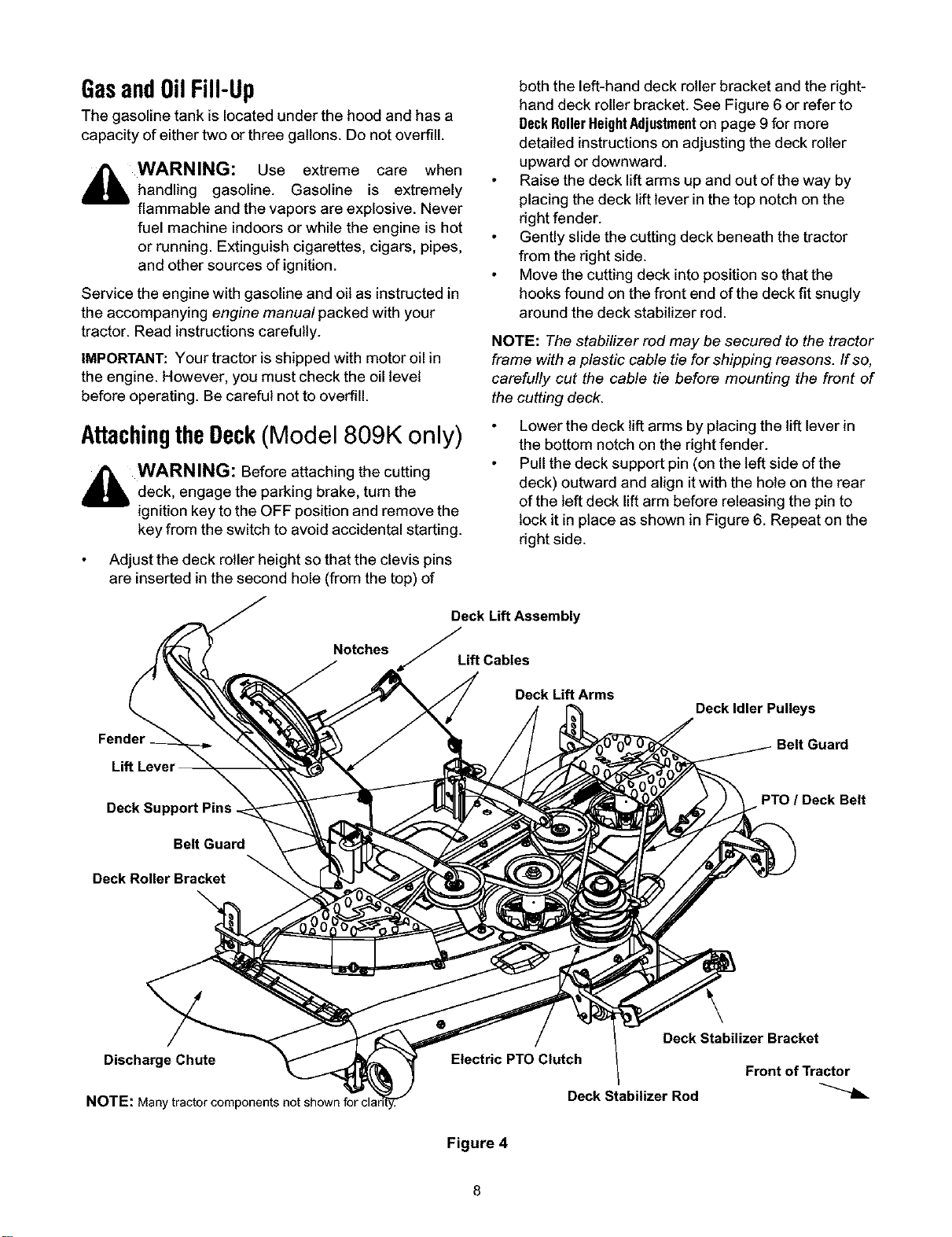
Adjust the deck roller height so that the clevis pins
are inserted in the second hole (from the top) of
Notches
Fender
both the left-hand deck roller bracket and the right-
hand deck roller bracket. See Figure 6 or refer to
DeckRollerHeightAdjustmenton page 9 for more
detailed instructions on adjusting the deck roller
upward or downward.
Raise the deck lift arms up and out of the way by
placing the deck lift lever in the top notch on the
right fender.
Gently slide the cutting deck beneath the tractor
from the right side.
Move the cutting deck into position so that the
hooks found on the front end of the deck fit snugly
around the deck stabilizer rod.
NOTE: The stabilizer rod may be secured to the tractor
frame with a plastic cable tie for shipping reasons. If so,
carefully cut the cable tie before mounting the front of
the cutting deck.
Lower the deck lift arms by placing the lift lever in
the bottom notch on the right fender.
Pull the deck support pin (on the left side of the
deck) outward and align itwith the hole on the rear
of the left deck lift arm before releasing the pin to
lock it in place as shown in Figure 6. Repeat on the
right side.
Deck Lift Assembly
Lift Cables
Deck Lift Arms
Deck Idler Pulleys
Deck Support Pins
Belt Guard
Deck Roller Bracket
PTO / Deck Belt
DischargeChute
NOTE: Many
Deck Stabilizer Bracket
Electric PTO Clutch
Front of Tractor
Deck Stabilizer Rod
Figure 4
Loading ...
Loading ...
Loading ...