Loading ...
Loading ...
Loading ...
DisengagePTO,moveshiftleverintotheneutral
position,settheparkingbrake,andstopengine.
Threadthehosecoupler(packagedwiththis
manual)ontotheendofyourgardenhose.
Attachthehosecouplertothewaterportonyour
deckssurface.SeeFigure14.
Turnthewateron.
Whilesittingintheoperator'spositiononthe
tractor,re-starttheengineandplacethethrottle
leverintheFAST(rabbit)position.
Engagethetractor'sPTO.
Remainintheoperator'spositionwiththecutting
deckengagedforaminimumoftwominutes,
allowingtheundersideofthecuttingdeckto
throughlyrinse.
Disengagethetractor'sPTO.
TurntheignitionkeytotheSTOPpositiontoturn
thetractor'sengineoff.
Turnthewateroffanddetachthehosecoupler
fromthewaterportonyourdeckssurface.Repeat
step4-11ontheoppositesideofthecuttingdeck.
Lubrication
Engine
WARNING: Before lubricating, repairing, or
inspecting, always disengage PTO, move
shift lever into neutral position, set parking
brake, stop engine and remove key to prevent
unintended starting.
Lubricate the engine with motor oil as instructed in the
Briggs & Stratton Operator/Owner Manual packed with
your unit.
PivotPoints& Linkage
Lubricate all the pivot points on the drive system,
parking brake and lift linkage at least once a season
with light oil.
FrontWheels
Each end of the tractor's front pivot bar is equipped with
a grease fitting. Lubricate with a grease gun after every
25 hours of tractor operation.
SECTION8: SERVICE
CuttingDeckRemoval
To remove the cutting deck, proceed as follows:
Place the PTO knob/lever in the "Blade Stop"
position and engage the parking brake.
Lower the deck by moving the deck lift lever into the
bottom notch on the right fender.
Remove the PTO belt from around the electric PTO
clutch or the engine pulley. Refer to Figure 16.
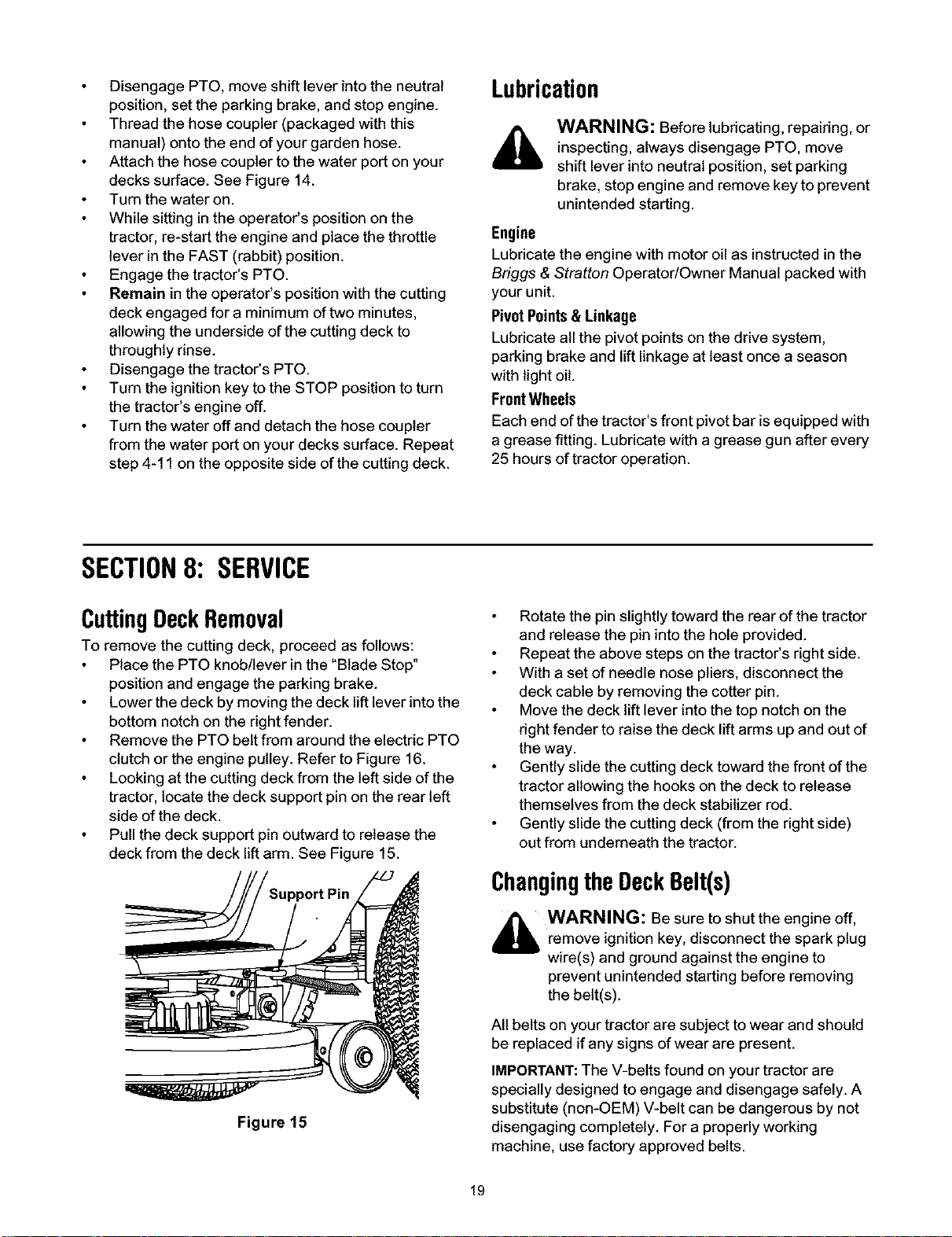
Looking at the cutting deck from the left side of the
tractor, locate the deck support pin on the rear left
side of the deck.
Pull the deck support pin outward to release the
deck from the deck lift arm. See Figure 15.
Figure 15
Rotate the pin slightly toward the rear of the tractor
and release the pin into the hole provided.
Repeat the above steps on the tractor's right side.
With a set of needle nose pliers, disconnect the
deck cable by removing the cotter pin.
Move the deck lift lever intothe top notch on the
right fender to raise the deck lift arms up and out of
the way.
Gently slide the cutting deck toward the front of the
tractor allowing the hooks on the deck to release
themselves from the deck stabilizer rod.
Gently slide the cutting deck (from the right side)
out from underneath the tractor.
ChangingtheDeckBelt(s)
_ WARNING: Be sure to shut the engine off,
remove ignition key, disconnect the spark plug
wire(s) and ground against the engine to
prevent unintended starting before removing
the belt(s).
All belts on your tractor are subject to wear and should
be replaced if any signs of wear are present.
IMPORTANT:The V-belts found on your tractor are
specially designed to engage and disengage safely. A
substitute (non-OEM) V-belt can be dangerous by not
disengaging completely. For a properly working
machine, use factory approved belts.
19
Loading ...
Loading ...
Loading ...