
TRilY RILT
Operator's Manual
Pedal Drive Garden Tractor
Horse TM
(Models T809H & Z809K)
IMPORTANT: Read safety rules and instructions carefully before operating equipment.
Warning: This unit is equipped with an internal combustion engine and should not be used on or near any unimproved forest-cov-
ered, brush-covered or grass-covered land unless the engine's exhaust system is equipped with a spark arrester meeting applicable
local or state laws (if any). If a spark arrester is used, it should be maintained in effective working order by the operator. In the State
of California the above is required by law (Section 4442 of the California Public Resources Code). Other states may have similar laws.
Federal laws apply on federal lands. A spark arrester for the muffler is available through your nearest engine authorized service dealer
or contact the service department, P.O. Box 361131 Cleveland, Ohio 44136-0019.
Troy-Bilt LLC,P.O.BOX361131CLEVELAND,OHIO44136-0019
PRINTED IN U.S.A.
FORM NO. 770-10189F
(11/2003)
TABLEOFCONTENTS
Content Page Content Page
Important Safe Operation Practices 3 Service 19
Tractor Set-Up 7 Off-Season Storage 24
Know Your Garden Tractor 10 Attachments&Accessories 25
Operating Your Garden Tractor 13 Troubleshooting 26
Making Adjustments 16 Illustrated Parts List 27
Maintaining Your Garden Tractor 18 Warranty 44
FINDINGMODELNUMBER
This Operator's Manual is an important part of your new lawn tractor. It will help you assemble, prepare and
maintain the unit for best performance. Please read and understand what it says.
Before you start assembling your new equipment, please locate the model plate under the
seat of the tractor and copy the information in the space provided below. A sample model plate is
also given below. This information will be necessary to use the manufacturer's web site and/or
help from the Customer Support Department or an authorized service dealer.
z
• TROY-BILT LLC
O _e_ _O. BOX 361131
www.trovbilt.com CL_E_NO,OH4413_
330-558-7220
• 866-840-6483
Copy the model number here:
Copy the serial number here:
CUSTOMERSUPPORT
PleasedoNOTretumtheunittotheretailer from whereit waspurchased,withoutfirstcontactingCustomerSupport.
If you have difficulty assembling this product or have any questions regarding the controls, operation or
maintenance of this unit, you can seek help from the experts. Choose from the options below:
Visit troybUt.com for many useful suggestions. Click on Customer Support button and you will
get the four options reproduced here. Click on the appropriate button and help is immediately
available.
_qhe answer you are
a mouse crick awa S
ll_o_llty _ol_J hL_l_lhi_ % _L _lj_l_t_ tJou_ N_L_OI_I
N_e_l Io_41 _ssP_tr_h_ ÷? Lli¢k he[e _e lh_J
To reach the Customer Support Line, please call 1-866-840-6483 or 1-330-558-7220.
The engine manufacturer is responsible for all engine-related issues with regards to
and service. Please refer to the
)erformance,
power-rating, specifications, warranty engine
manufacturer's Owner's/Operator's Manual, at the end of this manual, for more information.
SECTION1: IMPORTANTSAFEOPERATIONPRACTICES
,_ WARNING: This symbol points out important safety instructions which, if not followed, could endanger
the personal safety and/or property of yourself and others. Read and follow all instructions in this manual
before attempting to operate this machine. Failure to comply with these instructions may result in personal
injury. When you see this symbol--heed its warning.
DANGER: This machine was built to be operated according to the rules for safe operation in this manual.
As with any type of power equipment, carelessness or error on the part of the operator can result in serious
injury. This machine is capable of amputating hands and feet and throwing objects. Failure to observe the
following safety instructions could result in serious injury or death.
WARNING: Engine exhaust, some of its constituents, and certain vehicle components contain or
emit chemicals known to the State of California to cause cancer and birth defects or other
reproductive harm.
GeneralOperation
1. Read, understand, and follow all instructions on the
machine and in the manual(s) before attempting to
assemble and operate. Keep this manual in a safe place
for future and regular reference and for ordering
replacement parts.
2. Be familiar with all controls and their proper operation.
Know how to stop the machine and disengage them
quickly.
3. Never allow children under 14 years old to operate this
machine. Children 14 years old and over should read and
understand the operation instructions and safety rules in
this manual and should be trained and supervised by a
parent.
4. Never allow adults to operate this machine without proper
instruction.
5. To help avoid blade contact or a thrown object injury,
keep bystanders, helpers, children and pets at least 75
feet from the machine while it is in operation. Stop
machine if anyone enters the area.
6. Thoroughly inspect the area where the equipment is to be
used. Remove all stones, sticks, wire, bones, toys, and
other foreign objects which could be picked up and
thrown by the blade(s). Thrown objects can cause
serious personal injury.
7. Plan your mowing pattern to avoid discharge of material
toward roads, sidewalks, bystanders and the like. Also,
avoid discharging material against a wall or obstruction
which may cause discharged material to ricochet back
toward the operator.
8. Always wear safety glasses or safety goggles during
operation and while performing an adjustment or repair to
protect your eyes. Thrown objects which ricochet can
cause serious injury to the eyes.
9. Wear sturdy, rough-soled work shoes and close-fitting
slacks and shirts. Loose fitting clothes and jewelry can be
caught in movable parts. Never operate this machine in
bare feet or sandals.
10. Be aware of the mower and attachment discharge
direction and do not point it at anyone. Do not operate the
mower without the discharge cover or entire grass
catcher in its proper place.
11. Do not put hands or feet near rotating parts or under the
cutting deck. Contact with the blade(s) can amputate
hands and feet.
12. A missing or damaged discharge cover can cause blade
contact or thrown object injuries.
13. Stop the blade(s) when crossing gravel drives, walks, or
roads and while not cutting grass.
14. Watch for traffic when operating near or crossing
roadways. This machine is not intended for use on any
public roadway.
15. Do not operate the machine while under the influence of
alcohol or drugs.
16. Mow only in daylight or good artificial light.
17. Never carry passengers.
18. Disengageblade(s) before shifting into reverse. Backup
slowly. Always look down and behind before and while
backing to avoid a back-over accident.
19. Slow down before turning. Operate the machine
smoothly. Avoid erratic operation and excessive speed.
20. Disengage blade(s), set parking brake, stop engine and
wait until the blade(s) come to a complete stop before
removing grass catcher, emptying grass, unclogging
chute, removing any grass or debris, or making any
adjustments.
21. Never leave a running machine unattended. Always turn
off blade(s), place transmission in neutral, set parking
brake, stop engine and remove key before dismounting.
22. Use extra care when loading or unloading the machine
into a trailer or truck. This unit should not be driven up or
down ramp(s), because the unit could tip over, causing
serious personal injury. The unit must be pushed
manually on ramp(s) to load or unload properly.
23. Muffler and engine become hot and can cause a burn. Do
not touch.
24. Check overhead clearances carefully before driving
under low hanging tree branches, wires, door openings
etc., where the operator may be struck or pulled from the
unit, which could result in serious injury.
25. Disengage all attachment clutches, depress the brake
pedal completely and shift into neutral before attempting
to start engine.
26. Your machine is designed to cut normal residential grass
of a height no more than 10". Do not attempt to mow
throughunusuallytall,drygrass(e.g.,pasture)orpilesof
dryleaves.Drygrassorleavesmaycontacttheengine
exhaustand/orbuilduponthemowerdeckpresentinga
potentialfirehazard.
27.Useonlyaccessoriesandattachmentsapproved for this
machine by the machine manufacturer. Read,
understand and follow all instructions provided with the
approved accessory or attachment.
28. Data indicates that operators, age 60 years and above,
are involved in a large percentage of riding mower-
related injuries. These operators should evaluate their
ability to operate the riding mower safely enough to
protect themselves and others from serious injury.
29. If situations occur which are not covered in this manual,
use care and good judgment. Contact Troy-Bilt Customer
Support Line at 1-866-840-6483 for assistance.
SlopeOperation
Slopes are a major factor related to loss of control and tip-
over accidents which can result in severe injury or death. All
slopes require extra caution. If you cannot back up the slope
or if you feel uneasy on it, do not mow it.
For your safety, use the slope gauge included as part of this
manual to measure slopes before operating this unit on a
sloped or hilly area. If the slope is greater than 15 degrees as
shown on the slope gauge, do not operate this unit on that
area or serious injury could result.
Do:
1. Mow up and down slopes, not across. Exercise extreme
caution when changing direction on slopes.
2. Watch for holes, ruts, bumps, rocks, or other hidden
objects. Uneven terrain could overturn the machine. Tall
grass can hide obstacles.
3. Use slow speed. Choose a low enough speed setting so
that you will not have to stop or shift while on the slope.
Tires may lose traction on slopes even though the brakes
are functioning properly. Always keep machine in gear
when going down slopes to take advantage of engine
braking action.
4. Follow the manufacturer's recommendations for wheel
weights or counterweights to improve stability.
5. Use extra care with grass catchers or other attachments.
These can change the stability of the machine.
6. Keep all movement on the slopes slow and gradual. Do
not make sudden changes in speed or direction. Rapid
engagement or braking could cause the front of the
machine to lift and rapidly flip over backwards which
could cause serious injury.
7. Avoid starting or stopping on a slope. If tires lose traction,
disengage the blade(s) and proceed slowly straight down
the slope.
DoNot
1. Do not turn on slopes unless necessary; then, turn slowly
and gradually downhill, if possible.
2. Do not mow near drop-offs, ditches or embankments.
The mower could suddenly turn over if a wheel is over the
edge of a cliff, ditch, or if an edge caves in.
3. Do not try to stabilize the machine by putting your foot on
the ground.
4. Do not use a grass catcher on steep slopes.
5,
6.
7,
Do not mow on wet grass. It may cause sliding.
Do not shift to neutral and coast downhill. Over-speeding
may cause the operator to lose control of the machine
resulting in serious injury or death.
Do not tow heavy attachments (e.g. loaded dump cart,
lawn roller, etc.) on slopes greater than 5 degrees. When
going down hill, the extra weight tends to push the tractor
and may cause you to loose control. (e.g. tractor may
speed up, braking and steering ability may be reduced,
attachment may jack-knife and tractor may overturn).
Children
1. Tragic accidents can occur if the operator is not alert to
the presence of children. Children are often attracted to
the machine and the mowing activity. They do not
understand the dangers. Never assume that children will
remain where you last saw them.
a. Keep children out of the mowing area and in
watchful care of a responsible adult other than the
operator.Be alert and turn machine off if a child
enters area.
b. Before and while backing, look behind and down
for small children.
c. Never carry children, even with the blade(s) shut
off. They may fall off and be seriously injured or
interfere with safe machine operation.
d. Use extreme care when approaching blind
corners, doorways, shrubs, trees or other objects
that may block your vision of a child who may run
into the machine.
e. Disengage the cutting blade(s) before shifting in
reverse. The "No-Cut-in Reverse" feature is a
reminder not to cut in reverse and to help avoid
back over accidents. Do not defeat it.
f. Keep children away from hot or running engines.
They can suffer burns from a hot muffler.
g. Remove key when machine is unattended to
prevent unauthorized operation.
8. Never allow children under 14 years to operate the
machine. Children 14 years old and over should read and
understand the operation and safety rules in this manual
and should be trained and supervised by a parent.
Towing
1. Tow only with a machine that has a hitch designed for
towing. Do not attach towed equipment except at the
hitch point.
2. Follow the manufacturers recommendation for weight
limits for towed equipment and towing on slopes.
3. Never allow children or others in or on towed equipment.
4. On slopes, the weight of the towed equipment may cause
loss of traction and loss of control.
5. Travel slowly and allow extra distance to stop.
6. Do not shift to neutral and coast downhill.
Service
SafeHandlingOfGasoline:
1, To avoid personal injury or property damage use
extreme care in handling gasoline, Gasoline is
extremely flammable and the vapors are explosive.
Serious personal injury can occur when gasoline is
spilled on yourself or your clothes which can ignite. Wash
your skin and change clothes immediately.
a. Use only an approved gasoline container.
b. Never fill containers inside a vehicle or on a truck
or trailer bed with a plastic liner. Always place
containers on the ground away from your vehicle
before filling.
c. When practical, remove gas-powered equipment
from the truck or trailer and refuel it on the ground.
If this is not possible, then refuel such equipment
on a trailer with a portable container, rather than
from a gasoline dispenser nozzle.
d. Keep the nozzle in contact with the rim of the fuel
container opening at all times until fueling is
complete. Do not use a nozzle lock-open device.
e. Extinguish all cigarettes, cigars, pipes and other
sources of ignition.
f. Never fuel machine indoors.
g. Never remove gas cap or add fuel while the
engine is hot or running. Allow engine to cool at
least two minutes before refueling.
h. Never over fill fuel tank. Fill tank to no more than
½ inch below bottom of filler neck to allow space
for fuel expansion.
i. Replace gasoline cap and tighten securely.
j. If gasoline is spilled, wipe it off the engine and
equipment. Move unit to another area. Wait 5
minutes before starting the engine.
k. To reduce fire hazards, keep machine free of
grass, leaves, or other debris build-up. Clean up
oil or fuel spillage and remove any fuel soaked
debris.
L Never store the machine or fuel container inside
where there is an open flame, spark or pilot light
as on a water heater, space heater, furnace,
clothes dryer or other gas appliances.
m. Allow a machine to cool at least 5 minutes before
storing.
General Service:
1. Never run an engine indoors or in a poorly ventilated
area. Engine exhaust contains carbon monoxide, an
odorless, and deadly gas.
2. Before cleaning, repairing, or inspecting, make certain
the blade(s) and all moving parts have stopped.
Disconnect the spark plug wire and ground against the
engine to prevent unintended starting.
3. Periodically check to make sure the blades come to
complete stop within approximately (5) five seconds after
operating the blade disengagement control. Ifthe blades
do not stop within the this time frame, your unit should be
serviced professionally by an authorized Service Dealer.
4. Check brake operation frequently as it is subjected to
wear during normal operation. Adjust and service as
required.
5. Check the blade(s) and engine mounting bolts at
frequent intervals for proper tightness. Also, visually
inspect blade(s) for damage (e.g., excessive wear, bent,
cracked).
Replace the blade(s) with the original equipment
manufacturer's (O.EM.) blade(s) only, listed in this
manual. "Use of parts which do not meet the original
equipment specifications may lead to improper
performance and compromise safetyF
6. Mower blades are sharp. Wrap the blade or wear gloves,
and use extra caution when servicing them.
7. Keep all nuts, bolts, and screws tight to be sure the
equipment is in safe working condition.
8. Never tamper with the safety interlock system or other
safety devices. Check their proper operation regularly.
9. After striking aforeign object, stop the engine, disconnect
the spark plug wire(s) and ground against the engine.
Thoroughly inspect the machine for any damage. Repair
the damage before starting and operating.
10. Never attempt to make adjustments or repairs to the
machine while the engine is running.
11. Grass catcher components and the discharge cover are
subject to wear and damage which could expose moving
parts or allow objects to be thrown.
For safety protection, frequently check components and
replace immediately with original equipment
manufacturer's (O.EM.) parts only, listed in this manual.
"Use of parts which do not meet the original equipment
specifications may lead to improper performance and
compromise safetyF
12. Do not change the engine governor settings or over-
speed the engine. The governor controls the maximum
safe operating speed of the engine.
13. Maintain or replace safety and instruction labels, as
necessary.
14. Observe proper disposal laws and regulations for gas,
oil, etc. to protect the environment.
YourResponsibility
Restrict the use of this power machine to persons who
read, understand and follow the warnings and
instructions in this manual and on the machine,

W
ILl
..I
&i
Z
i
I,LI
,11
I
SIGHT AND HOLD THIS LEVEL WITH A VERTICAL TREE
A POWER POLE
A CORNER OF A BUILDING
OR A FENCE POST
i_ WARNING
Do not mow on inclines with a slope in excess of 15 degrees (a rise of approximately 2-1/2 feet every 10 feet). A riding mower
could overturn and cause serious injury. If operating a walk-behind mower on such a slope, it is extremely difficult to maintain
your footing and you could slip, resulting in serious injury.
Operate RIDING mowers up and down slopes, never across the face of slopes.
£O
SECTION3: SETTINGUPTHETRACTOR
NOTE: Any reference here to the RIGHT or LEFT side
of the tractor is observed from operator's position.
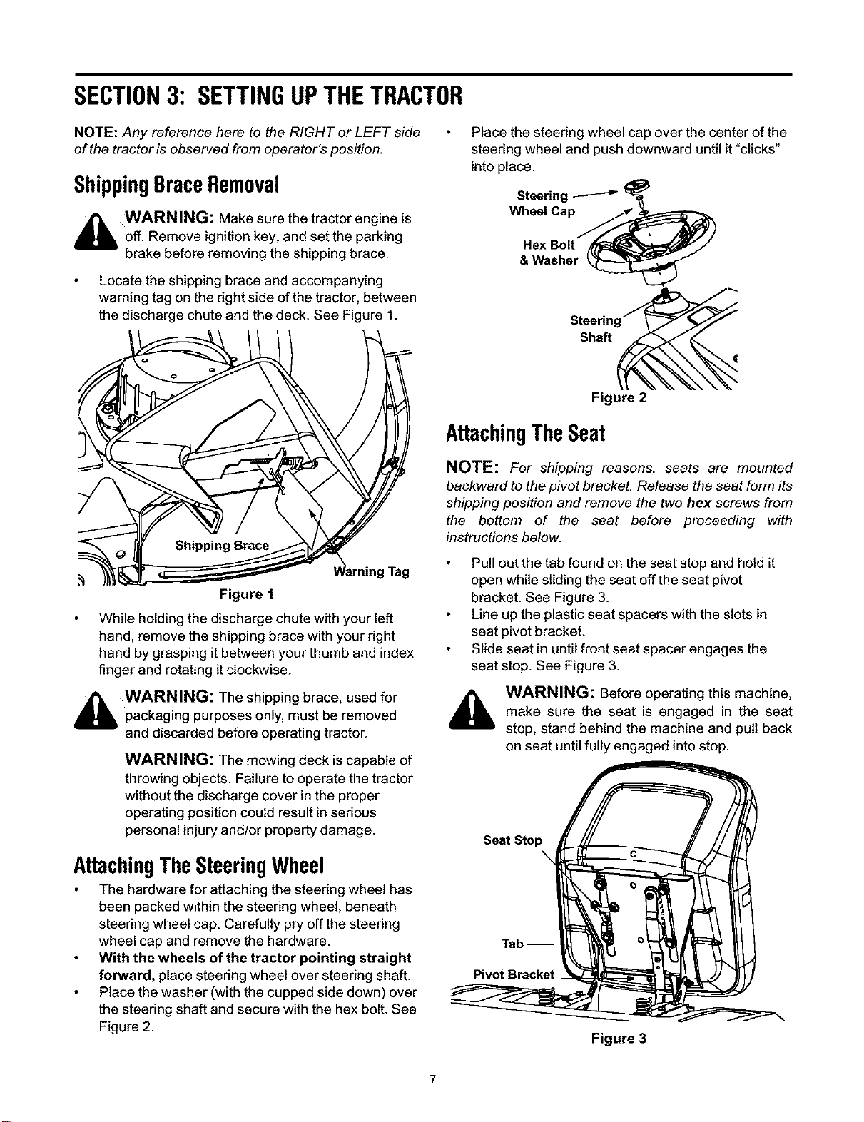
ShippingBraceRemoval
_ WARNING: Make sure the tractor engine is
off. Remove ignition key, and set the parking
brake before removing the shipping brace.
Locate the shipping brace and accompanying
warning tag on the right side of the tractor, between
the discharge chute and the deck. See Figure 1.
Figure 1
While holding the discharge chute with your left
hand, remove the shipping brace with your right
hand by grasping it between your thumb and index
finger and rotating it clockwise.
_i WARNING: The shipping brace, used for
packaging purposes only, must be removed
and discarded before operating tractor.
WARNING: The mowing deck is capable of
throwing objects. Failure to operate the tractor
without the discharge cover in the proper
operating position could result in serious
personal injury and/or property damage.
AttachingTheSteeringWheel
The hardware for attaching the steering wheel has
been packed within the steering wheel, beneath
steering wheel cap. Carefully pry offthe steering
wheel cap and remove the hardware.
With the wheels of the tractor pointing straight
forward, place steering wheel over steering shaft.
Place the washer (with the cupped side down) over
the steering shaft and secure with the hex bolt. See
Figure 2.
Place the steering wheel cap over the center of the
steering wheel and push downward until it "clicks"
into place.
Steering _ _
Wheel Capri,
Hex Bolt
& Washer _
Steering'_
Shaft _
Figure 2
AttachingTheSeat
NOTE: For shipping masons, seats are mounted
backward to the pivot bracket. Release the seat form its
shipping position and remove the two hex screws from
the bottom of the seat before proceeding with
instructions below.
Pull out the tab found on the seat stop and hold it
open while sliding the seat off the seat pivot
bracket. See Figure 3.
Line up the plastic seat spacers with the slots in
seat pivot bracket.
Slide seat in until front seat spacer engages the
seat stop. See Figure 3.
WARNING: Before operating this machine,
make sure the seat is engaged in the seat
stop, stand behind the machine and pull back
on seat until fully engaged into stop.
Seat Stop
X
Pivot Bracket
Figure 3
GasandOilFill-Up
The gasoline tank is located under the hood and has a
capacity of either two or three gallons. Do not overfill.
_WARNING: Use extreme care when
handling gasoline. Gasoline is extremely
flammable and the vapors are explosive. Never
fuel machine indoors or while the engine is hot
or running. Extinguish cigarettes, cigars, pipes,
and other sources of ignition.
Service the engine with gasoline and oil as instructed in
the accompanying engine manual packed with your
tractor. Read instructions carefully.
IMPORTANT: Your tractor is shipped with motor oil in
the engine. However, you must check the oil level
before operating. Be careful not to overfill.
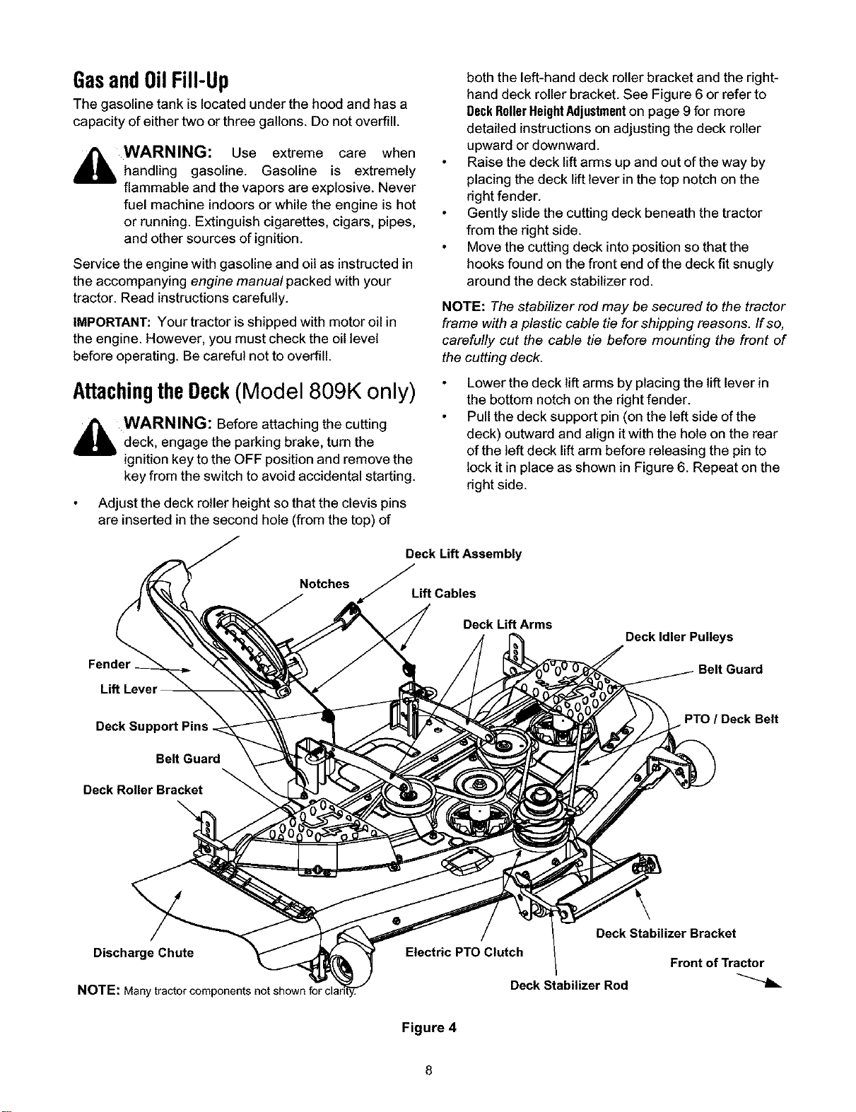
AttachingtheDeck(Model 809K only)
,_ WARNING: Before attaching the cutting
deck, engage the parking brake, turn the
ignition key to the OFF position and remove the
key from the switch to avoid accidental starting.
Adjust the deck roller height so that the clevis pins
are inserted in the second hole (from the top) of
Notches
Fender
both the left-hand deck roller bracket and the right-
hand deck roller bracket. See Figure 6 or refer to
DeckRollerHeightAdjustmenton page 9 for more
detailed instructions on adjusting the deck roller
upward or downward.
Raise the deck lift arms up and out of the way by
placing the deck lift lever in the top notch on the
right fender.
Gently slide the cutting deck beneath the tractor
from the right side.
Move the cutting deck into position so that the
hooks found on the front end of the deck fit snugly
around the deck stabilizer rod.
NOTE: The stabilizer rod may be secured to the tractor
frame with a plastic cable tie for shipping reasons. If so,
carefully cut the cable tie before mounting the front of
the cutting deck.
Lower the deck lift arms by placing the lift lever in
the bottom notch on the right fender.
Pull the deck support pin (on the left side of the
deck) outward and align itwith the hole on the rear
of the left deck lift arm before releasing the pin to
lock it in place as shown in Figure 6. Repeat on the
right side.
Deck Lift Assembly
Lift Cables
Deck Lift Arms
Deck Idler Pulleys
Deck Support Pins
Belt Guard
Deck Roller Bracket
PTO / Deck Belt
DischargeChute
NOTE: Many
Deck Stabilizer Bracket
Electric PTO Clutch
Front of Tractor
Deck Stabilizer Rod
Figure 4
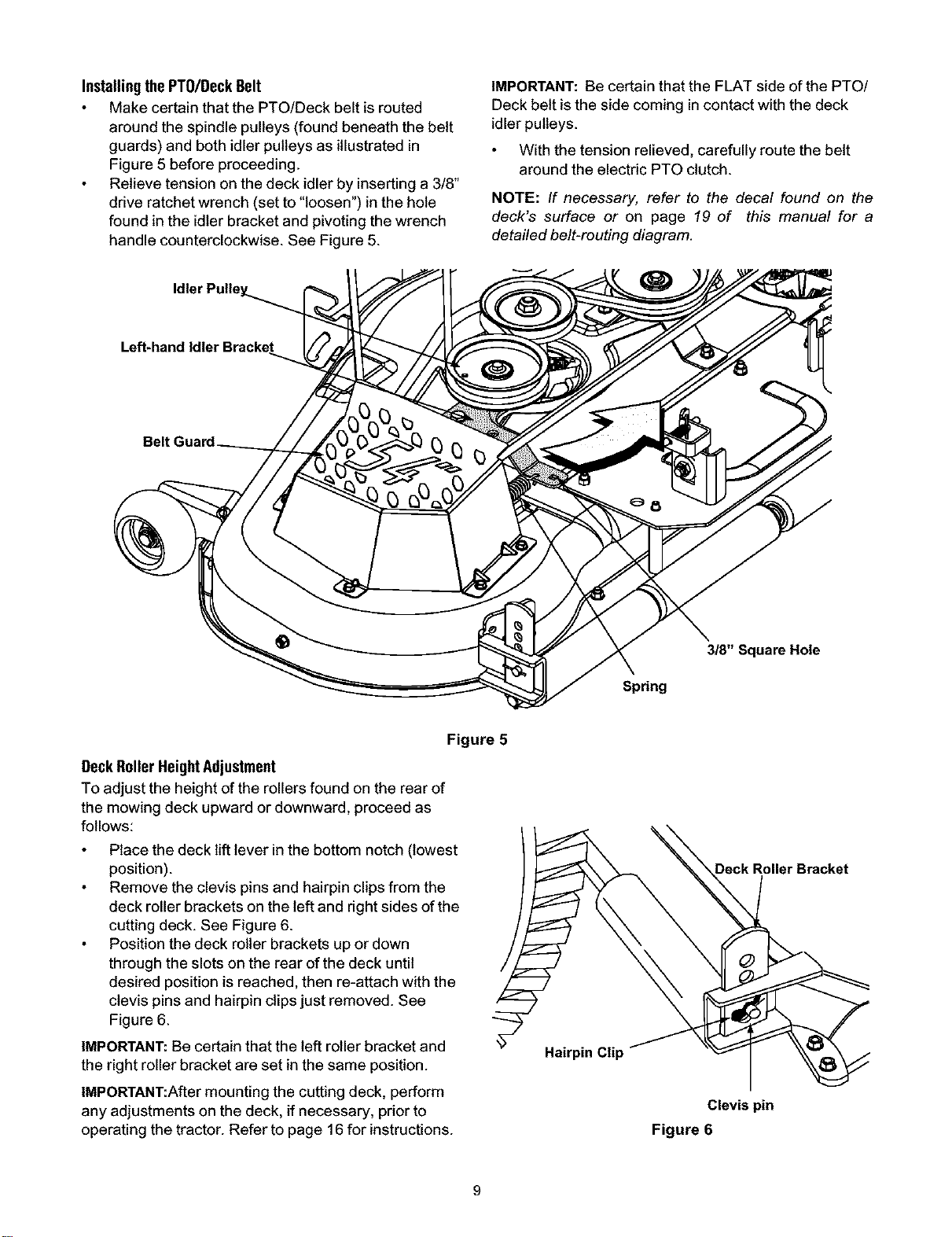
Installingthe PT0/Deck Belt
Make certain that the PTO!Deck belt is routed
around the spindle pulleys (found beneath the belt
guards) and both idler pulleys as illustrated in
Figure 5 before proceeding.
Relieve tension on the deck idler by inserting a 3/8"
drive ratchet wrench (set to "loosen") in the hole
found in the idler bracket and pivoting the wrench
handle counterclockwise. See Figure 5.
IMPORTANT: Be certain that the FLAT side of the PTO/
Deck belt is the side coming in contact with the deck
idler pulleys.
With the tension relieved, carefully route the belt
around the electric PTO clutch.
NOTE: If necessary, refer to the decal found on the
deck's surface or on page 19 of this manual for a
detailed belt-routing diagram.
3/8" Square Hole
Spring
Figure 5
Beck RollerHeightAdjustment
To adjust the height of the rollersfound on the rear of
the mowing deck upward or downward, proceed as
follows:
Place the deck lift lever inthe bottom notch (lowest
position).
Remove the clevis pins and hairpin clips from the
deck roller brackets on the left and right sides of the
cutting deck. See Figure 6.
Position the deck roller brackets up or down
through the slots on the rear of the deck until
desired position is reached, then re-attach with the
clevis pins and hairpin clips just removed. See
Figure 6.
IMPORTANT:Be certain that the left roller bracket and
the right roller bracket are set in the same position.
IMPORTANT:After mounting the cutting deck, perform
any adjustments on the deck, if necessary, prior to
operating the tractor. Refer to page 16 for instructions.
Hairpin Clip
Deck Roller Bracket
Clevis pin
Figure 6
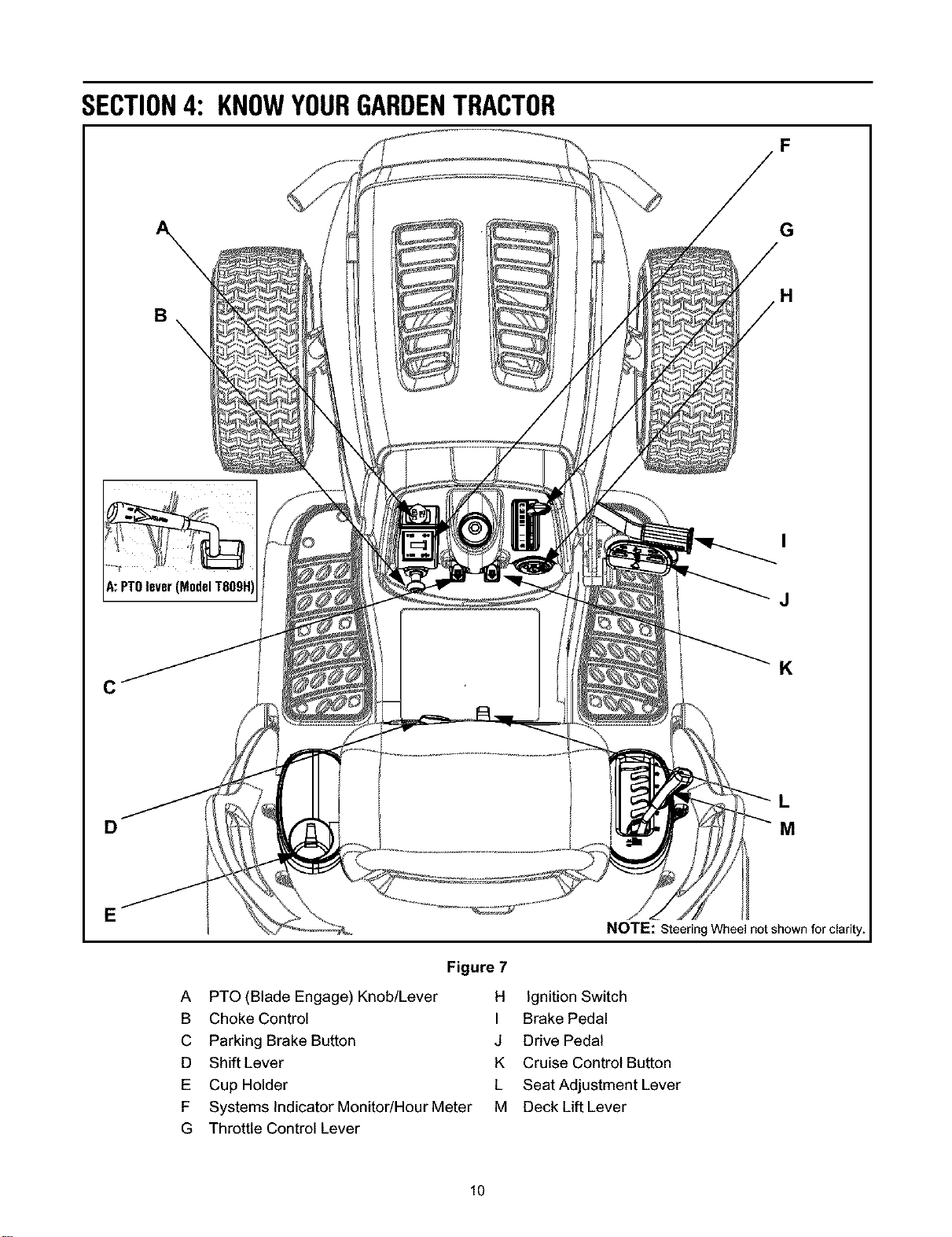
SECTION4: KNOWYOURGARDENTRACTOR
F
\
B
G
H
A:PTOleverq
I
J
C
K
D
L
M
A PTO(Blade Engage) Knob/Lever
B Choke Control
C Parking Brake Button
D Shift Lever
E Cup Holder
F Systems Indicator Monitor/HourMeter
G Throttle Control Lever
Figure7
H
Ignition Switch
I Brake Pedal
J Drive Pedal
K Cruise ControtButton
L Seat Adjustment Lever
M Deck Lift Lever
Wheel not shown
10
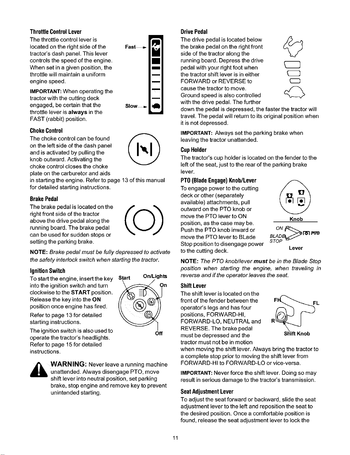
ThrottleControlLever
The throttle control lever is
located on the right side of the Fas_
tractor's dash panel. This lever
controls the speed of the engine.
When set in a given position, the
throttle will maintain a uniform
engine speed.
IMPORTANT:When operating the
tractor with the cutting deck
engaged, be certain that the SIo_
throttle lever is always in the
FAST (rabbit) position.
ChokeControl
The choke control can be found //- "_
on the left side of the dash panel
and is activated by pulling the
knob outward. Activating the
choke control closes the choke
plate on the carburetor and aids
in starting the engine. Refer to page 13 of this manual
for detailed starting instructions.
Brake Pedal
The brake pedal is located on the
fight front side of the tractor
above the drive pedal along the
running board. The brake pedal
can be used for sudden stops or
setting the parking brake.
NOTE: Brake pedal must be fully depressed to activate
the safety interlock switch when starting the tractor.
IgnitionSwitch
To start the engine, insert the key
into the ignition switch and turn
clockwise to the START position.
Release the key intothe ON
position once engine has fired.
Refer to page 13 for detailed
starting instructions.
The ignition switch is also used to
operate the tractor's headlights.
Refer to page 15 for detailed
instructions.
Start On/Lights
Off
,_ WARNING: Never leave a running machine
unattended. Always disengage PTO, move
shift lever into neutral position, set parking
brake, stop engine and remove key to prevent
unintended starting.
DrivePedal
The drive pedal is located below j_..._j)
the brake pedal on the right front
side of the tractor along the
running board. Depress the drive
pedal with your fight foot when
the tractor shift lever is in either
FORWARD or REVERSE to
cause the tractor to move.
Ground speed isalso controlled
with the drive pedal. The further
down the pedal is depressed, the faster the tractor will
travel. The pedal will return to its original position when
it is not depressed.
IMPORTANT: Always set the parking brake when
leaving the tractor unattended.
CupHolder
The tractor's cup holder is located on the fender to the
left of the seat, just to the rear of the parking brake
lever.
PTO(BladeEngage)Knob/Lever
To engage power to the cutting
deck or other (separately
available) attachments, pull
outward on the PTO knob or
move the PTO lever to ON Knob
position, as the case may be.
Push the PTO knob inward or
move the PTO lever to BLade
Stop position to disengage power
to the cutting deck. Lever
oNf,
BLADE_._ / 1-61
STOP _-
NOTE: The PTO knob/lever must be in the Blade Stop
position when starting the engine, when travefing in
reverse and if the operator leaves the seat.
ShiftLever
The shift lever is located on the
front of the fender between the
operator's legs and has four
positions, FORWARD-HI,
FORWARD-LO, NEUTRAL and
REVERSE. The brake pedal
must be depressed and the
tractor must not be in motion
when moving the shift lever. Always bring the tractor to
a complete stop prior to moving the shift lever from
FORWARD-HI to FORWARD-LO or vice-versa.
IMPORTANT: Never force the shift lever. Doing so may
result in serious damage to the tractor's transmission.
SeatAdjustmentLever
To adjust the seat forward or backward, slide the seat
adjustment lever to the left and reposition the seat to
the desired position. Once a comfortable position is
found, release the seat adjustment lever to lock the
11
seat in place. Refer to SeatAdjustmenton page 17 of this
manual for more detailed instructions.
DeckLift Lever
Found on your tractor's right fender, the deck lift lever is
used to change the height of the cutting deck. To use,
move the lever to the left, then place in the notch best
suited for your application.
Parking BrakeButton
To set the parking brake, fully /f_"_
depress the brake pedal and
push the parking brake button in.
Hold the button in while taking
your foot off the brake pedal.
Both the parking button and the
brake pedal will then stay
depressed. To release the
parking brake, depress the brake
pedal slightly. The parking brake
button will then return to its
original position.
NOTE: The parking brake must be set if the operator
leaves the seat with the engine running or the engine
will automatically shut of_
IMPORTANT: Always set the parking brake when
leaving the tractor unattended.
CruiseControlButton
The cruise control button is
located on the tractor dash panel
to the left of the ignition switch. ;i_
Push the cruise control button
while traveling forward at a
desired speed. While holding the
button in, release pressure from
the drive pedal. This will engage
the cruise control and allow the
tractor to remain at that speed
without applying pressure to the
drive pedal. Depress the brake pedal or the drive pedal
to deactivate cruise control. Refer to Operationssection
in this manual for detailed instructions.
NOTE: Cruise control can not be engaged at the
tractor's fastest ground speed. If the operator should
attempt to do so, the tractor will automatically
decelerate to the fastest optimal mowing ground speed.
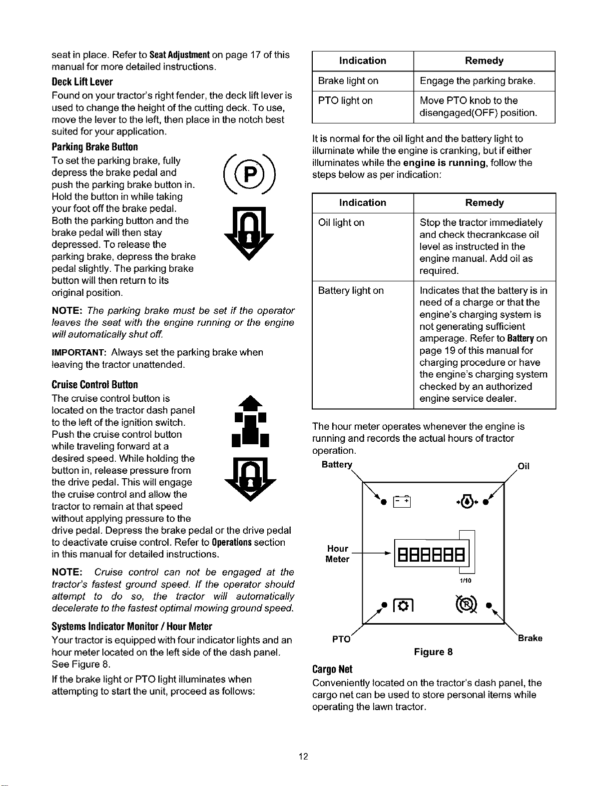
SystemsIndicator Monitor/ HourMeter
Your tractor is equipped with four indicator lights and an
hour meter located on the left side of the dash panel.
See Figure 8.
If the brake light or PTO light illuminates when
attempting to start the unit, proceed as follows:
Indication Remedy
Brake light on Engage the parking brake.
PTO light on Move PTO knob to the
disengaged(OFF) position.
It is normal for the oil light and the battery light to
illuminate while the engine is cranking, but if either
illuminates while the engine is running, follow the
steps below as per indication:
Indication Remedy
Oil light on Stop the tractor immediately
and check thecrankcase oil
level as instructed in the
engine manual. Add oil as
required.
Battery light on Indicates that the battery is in
need of a charge or that the
engine's charging system is
not generating sufficient
amperage. Refer to Batteryon
page 19 of this manual for
charging procedure or have
the engine's charging system
checked by an authorized
engine service dealer.
The hour meter operates whenever the engine is
running and records the actual hours of tractor
operation.
Battery Oil
Hour
Meter
/" %
PTO / \Brake
Figure 8
CargoNet
Conveniently located on the tractor's dash panel, the
cargo net can be used to store personal items while
operating the lawn tractor.
12
SECTION5: OPERATINGYOURGARDENTRACTOR
WARNING
AVOIDSERIOUSINJURYORDEATH
• GO UP AND DOWN SLOPES, NOT ACROSS.
• AVOID SUDDEN TURNS.
• DO NOT OPERATE THE UNiT WHERE iT COULD SLiP OR TIP.
• IF MACHINE STOPS GOING UPHILL, STOP BLADE(S) AND BACK
DOWNHILL SLOWLY.
• DO NOT MOW WHEN CHILDREN OR OTHERS ARE AROUND.
• NEVER CARRY CHILDREN, EVEN WiTH BLADES OFE
• LOOK DOWN AND BEHIND BEFORE AND WHILE BACKING.
• KEEP SAFETY DEVICES (GUARDS, SHIELDS, AND SWITCHES) IN
PLACE AND WORKING.
• REMOVE OBJECTS THAT COULD BE THROWN BY THE BLADE(S).
• KNOW LOCATION AND FUNCTION OF ALL CONTROLS.
• BE SURE BLADE(S) AND ENGINE ARE STOPPED BEFORE PLAC-
ING HANDS OR FEET NEAR BLADE(S).
• BEFORE LEAVING OPERATOR'S POSiTiON, DISENGAGE
BLADE(S), PLACE THE SHIFT LEVER IN NEUTRAL, ENGAGE
BRAKE LOCK, SHUT ENGINE OFF AND REMOVE KE_
READOPERATOR'SMANUAL
SafetyInterlockSwitches
This tractor is equipped with a safety interlock system
for the protection of the operator. If the interlock system
should ever malfunction, do not operate the tractor.
Contact an authorized service dealer. The safety
interlock system prevents the engine from cranking or
starting unless the parking brake isengaged, and the
PTO knob!lever is in the "Blade Stop" position.
The engine will automatically shut off if:
1. The operator leaves the seat before engaging the
parking brake;
2. The operator leaves the tractor's seat with the PTO
knob/lever in the ON position, regardless of
whether the parking brake isengaged; and
3. The PTO knob!lever is moved to ON position with
the shift lever in position for reverse travel.
_ WARNING: Do not operate the tractor if the
interlock system is malfunctioning. This system
was designed for your safety and protection.
SettingtheCuttingHeight
Select the height position of the cutting deck by
placing the deck lift lever in any of the six different
cutting height notches on the dght side of the
fender.
Adjust the deck wheels so that they are between ¼-
inch and ¼-inch above the ground when the tractor
is on a smooth, flat surface such as a driveway.
_ WARNING: Keep hands and feet away from
the discharge opening of the cutting deck.
NOTE: The deck wheels are an anti-scalp feature of the
deck and are not designed to support the weight of the
cutting deck.
Refer toLevelingtheDeckon page 16 of this manual for
more detailed instructionsregardingvarious deck
adjustments.
Startingthe Engine
NOTE: Referto page 7 of this manual for gasoline and
oil fill-up instructions.
Insert the tractor key intothe ignitionswitch.
Place the PTO knob/lever in the "Blade Stop"
position.
Engage the tractor's parking brake.
Place the throttle control inthe FAST (rabbit)
position.
Pull the choke control outward.
Turn the ignitionkey clockwise to the START
position. After the engine starts, release the key. It
will return to the ON position.
IMPORTANT: Do not hold the key inthe START position
for longer than ten seconds at a time. Doing so may
cause damage to your engine's electric starter.
After the engine starts, deactivate the choke control
and place the throttle control in the FAST position.
NOTE: Do not leave the choke control on while
operating the tractor. Doing so will result in a "rich" fuel
mixture and cause the engine to run poorly.
Stoppingthe Engine
,_ WARNING: If you strike a foreign object,
stop the engine, disconnect the spark plug
wire(s) and ground against the engine.
Thoroughly inspect the machine for any
damage. Repair the damage before restarting
and operating.
If the blades are engaged, place the PTO knob/
lever in the "Blade Stop" position.
Turn the ignitionkey counterclockwise to the OFF
position.
Remove the key from the ignition switch to prevent
unintended starting.
DrivingTheTractor
IMPORTANT:Avoid sudden starts, excessive speed and
sudden stops.
13
_ WARNING: Do not leave the seat of the
tractor without first placing the PTO knob in the
disengaged (OFF) position, depressing the
brake pedal and engaging the parking brake. If
leaving the tractor unattended, also turn the
ignition key off and remove the key.
Depress the brake pedal to release the parking
brake and let the pedal up. Move the throttle lever
into the FAST (rabbit) position.
IMPORTANT: Do not use the shift lever to change the
direction of travel when the tractor is in motion. Always
use the brake pedal to bring the tractor to a complete
stop before shifting.
To move forward, place the shift lever in the
FORWARD position, then slowly depress the drive
pedal until the desired speed is achieved.
To move in reverse, place the shift lever in the
REVERSE position, check that the area behind is
clear then slowly depress the drive pedal.
EngagingtheParkingBrake
To engage the parking brake:
Fully depress the brake pedal and hold itthere
while gently pushing the parking brake button
inward.
Hold the parking brake button in while removing
your foot from the brake pedal.
Once engaged, the parking brake button and the
brake pedal will lock in the DOWN position.
To disengage the parking brake:
Slightly depress the brake pedal.
NOTE: The parking brake must be engaged if the
operator leaves the seat with the engine running or the
engine will automatically shut oft
OperatingtheHeadlights
To turn the tractor's headlights on:
Start the engine following the instructions earlier in
this section.
Turn the key one notch counterclockwise into the
On!LightS position of the ignition switch. Refer to
figure on page 11.
To turn the tractor's headlights off:
Turn the key either to the ON position (to leave the
engine running) or the OFF position (to shut the
engine off).
NOTE: Never move the key into the Start position while
the engine is running. Doing so may cause damage to
your engine's electric starter.
DrivingOnSlopes
Refer to the SlopeGaugeon page 6 to help determine
slopes where you may operate the tractor safely.
,i_ WARNING: Do not mow on inclines with a
slope in excess of 15 degrees (a rise of
approximately 2-1/2 feet every 10 feet). The
tractor could overturn and cause serious injury.
Mow up and down slopes, never across.
Exercise extreme caution when changing direction
on slopes.
Watch for holes, ruts, bumps, rocks, or other
hidden objects. Uneven terrain could overturn the
machine. Tall grass can hide obstacles.
Avoid turns when driving on a slope. If a turn must
be made, turn downwards on the slope. Turning
upwards on a slope greatly increases the chance of
a roll-over.
Avoid stopping when driving up a slope. If it is
necessary to stop while driving up a slope, start up
smoothly and carefully to reduce the possibility of
flipping the tractor over backward.
SettingtheCruiseControl
NOTE: The cruise control feature should only be
utilized while traveling in the forward direction.
EngagingCruiseControl
Place the shift lever in the FORWARD position,
then slowly depress the drive pedal until the desired
speed is achieved.
Lightly depress the cruise control button.
While continuing to hold the cruise button in, lift
your foot from the drive pedal (you should feel the
cruise latch engage).
Once engaged, the cruise control button and the
drive pedal will lock in the DOWN position, and the
tractor will maintain the same forward speed.
NOTE: Cruise control cannot be engaged at the
tractor's fastest ground speed. If the operator should
attempt to do so, the tractor will automatically
decelerate to the fastest optimal mowing ground speed.
DisengagingCruiseControl
Choose one of the following two methods:
1. Depress the brake pedal to disengage the cruise
control and stop the tractor.
2. Lightly depress the drive pedal.
Changingto ReversewhenCruiseControlisEngaged
Depress the brake pedal to disengage the cruise
control and bring the tractor to a complete stop.
Place the shift lever in the REVERSE position, look
to the rear to ensure the path is empty, and depress
the drive pedal.
14

UsingtheDeckLiftLever
To raise the cutting deck, move the deck lift lever to the
left, then place it in the notch best suited for your
application. Refer to SettingTheCuttingHeightearlier in
this section.
Engagingthe PTOKnob/Lever
Engaging the PTO transfers power to the cutting deck
or other (separately available) attachments.
PTOKnob(Model Z809K)
To engage the PTO, move the throttle control lever
to the FAST (rabbit) position. Pull the PTO knob
outward to the ON position. See Figure 9.
NOTE: Keep the throttle lever in the FAST (rabbit)
position for the most efficient use of the cutting deck or
other (separately available) attachments.
Front View PullOut Push In
t
Figure 9
IMPORTANT: The electric PTO clutch will automatically
shut off if the PTO is engaged with the shift lever in
position for reverse travel. Refer to SafetyInterlock
Switcheson page 13.
To disengage the PTO, push the PTO knob in to
the "Blade Stop" position. See Figure 9.
PT0 Lever (Model TS09H)
To engage the PTO, move the throttle control lever
to the FAST (rabbit) position. Grasp the PTO (Blade
Engage) lever and pivot it all the way forward to the
ON position.
NOTE: Keep the throttle lever in the FAST (rabbit)
position for most efficient use of the cutting deck or
other (separately available) attachments.
To disengage the PTO, move the PTO lever to the
"Blade Stop" position. This will cut off power to deck
or other attachments.
Mowing
_WARNING: To help avoid blade contact or a
thrown object injury, keep bystanders, helpers,
children and pets at least 75 feet from the
machine while it isin operation. Stop machine if
anyone enters the area.
The following information wilt be helpful when using the
cutting deck with your tractor.
_ WARNING: Plan your mowing pattern to
avoid discharge of materials toward roads,
sidewalks, bystanders and the like. Also, avoid
discharging material against a wall or
obstruction which may cause discharged
material to ricochet back toward the operator.
Do not mow at high ground speed, especially if a
mulch kit or grass collector is installed.
For best results it is recommended that the first two
laps be cut with the discharge thrown towards the
center. After the first two laps, reverse the direction
to throw the discharge to the outside for the
balance of cutting. This will give a better
appearance to the lawn.
Do not cut the grass too short. Short grass invites
weed growth and yellows quickly in dry weather.
Mowing should always be done with the engine at
full throttle.
In heavier conditions, it may be better to go back
over the cut area a second time to get a clean cut.
Do not attempt to mow heavy brush and weeds and
extremely tall grass. Your tractor is designed to
mow lawns, not clear brush.
Keep the blades sharp and replace the blades
when worn. Refer to CuttingBladeson page 22 of this
manual for proper blade sharpening instructions.
15
SECTION6: MAKINGADJUSTMENTS
,_ WARNING: Never attempt to make any
adjustments while the engine is running,
except where specified in the manual.
WARNING: Disconnect the spark plug
wire(s) and ground against the engine before /
performing any adjustments, repairs or
maintenance.
ParkingBrake
_'_ WARNING: Never attemptto adjust the
brakes while the engine is running. Always
disengage PTO, move shift lever into neutral
position, stop engine and remove key to
prevent unintended starting.
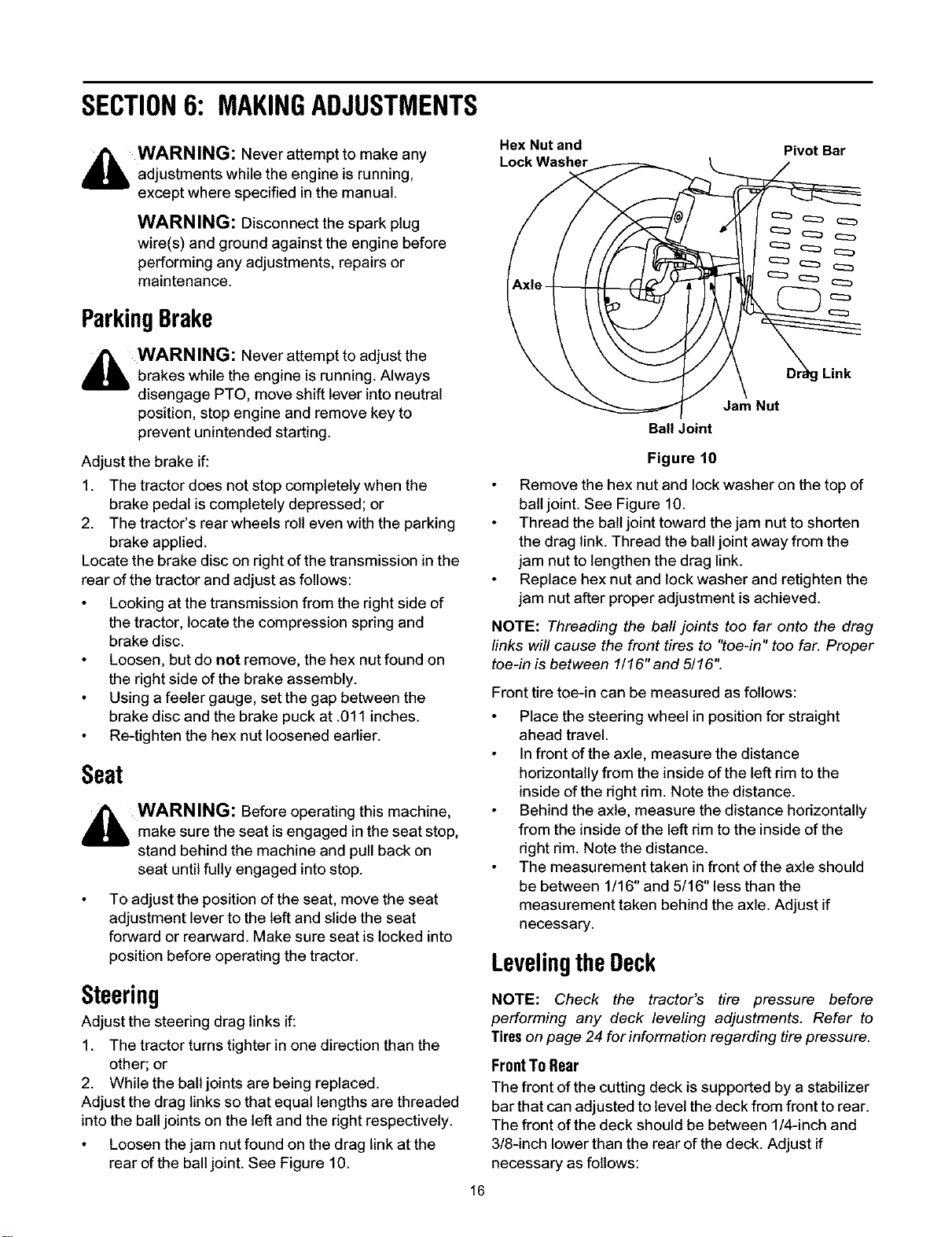
Hex Nut and
Lock Washer
Pivot Bar
Jam Nut
Ball Joint
Adjust the brake if:
Figure 10
1. The tractor does not stop completely when the
brake pedal is completely depressed; or
2. The tractor's rear wheels roll even with the parking
brake applied.
Locate the brake disc on right of the transmission in the
rear of the tractor and adjust as follows:
Looking at the transmission from the right side of
the tractor, locate the compression spring and
brake disc.
Loosen, but do not remove, the hex nut found on
the right side of the brake assembly.
Using a feeler gauge, set the gap between the
brake disc and the brake puck at .011 inches.
Re-tighten the hex nut loosened eadier.
Seat
,_ WARNING: Before operating this machine,
make sure the seat is engaged in the seat stop,
stand behind the machine and pull back on
seat until fully engaged into stop.
To adjust the position of the seat, move the seat
adjustment lever to the left and slide the seat
forward or rearward. Make sure seat is locked into
position before operating the tractor.
Steering
Adjust the steering drag links if:
1. The tractor turns tighter in one direction than the
other; or
2. While the ball joints are being replaced.
Adjust the drag links so that equal lengths are threaded
into the ball joints on the left and the dght respectively.
Loosen the jam nut found on the drag link at the
rear of the ball joint. See Figure 10.
Remove the hex nut and lock washer on the top of
ball joint. See Figure 10.
Thread the ball joint toward the jam nut to shorten
the drag link. Thread the ball joint away from the
jam nut to lengthen the drag link.
Replace hex nut and lock washer and retighten the
jam nut after proper adjustment is achieved.
NOTE: Threading the ball joints too far onto the drag
finks will cause the front tires to "toe-in" too far. Proper
toe-in is between 1/16" and 5/16".
Front tire toe-in can be measured as follows:
Place the steering wheel in positionfor straight
ahead travel.
In front of the axle, measure the distance
hodzontally from the inside of the left dm to the
inside of the dght rim. Note the distance.
Behind the axle, measure the distance horizontally
from the inside of the left dm to the inside of the
dght rim. Note the distance.
The measurement taken in front of the axle should
be between 1/16" and 5/16" less than the
measurement taken behind the axle. Adjust if
necessary.
Levelingthe Deck
NOTE: Check the tractor's tire pressure before
performing any deck leveling adjustments. Refer to
Tires on page 24 for information regarding tire pressure.
FrontTo Rear
The front of the cutting deck is supported by a stabilizer
bar that can adjusted to level the deck from front to rear.
The front of the deck should be between 1!4-inch and
3/8-inch lower than the rear of the deck. Adjust if
necessary as follows:
16
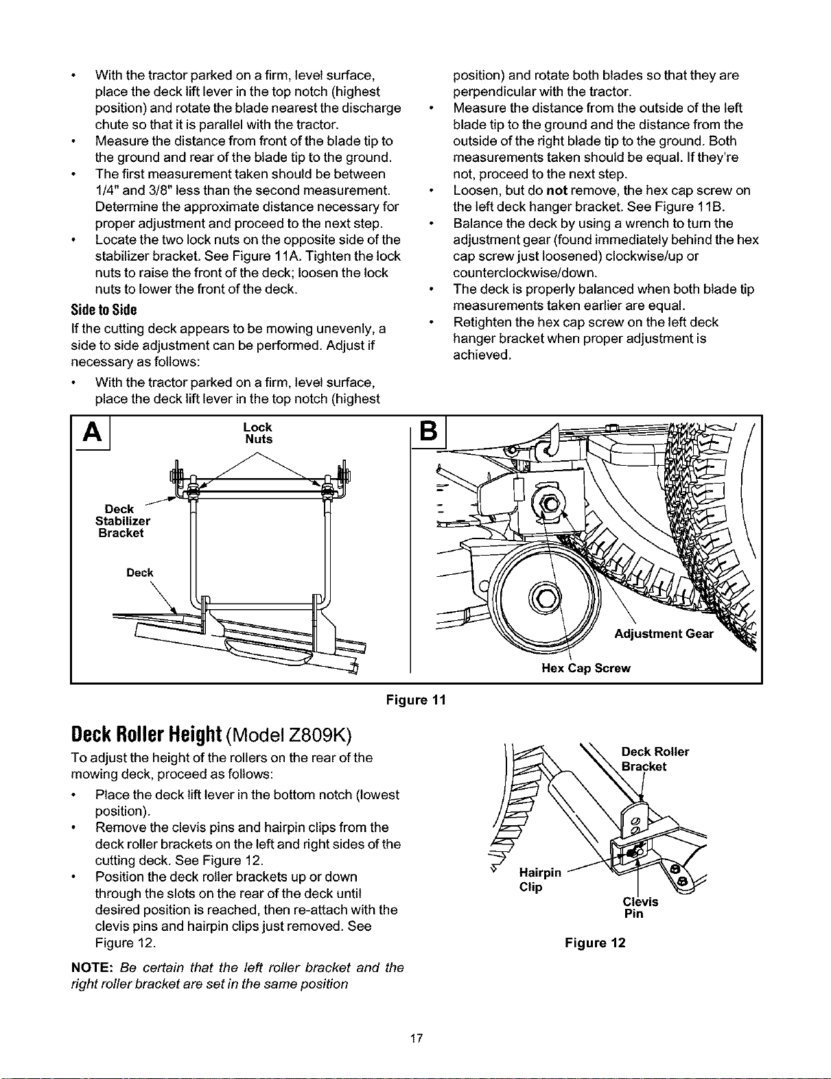
Withthetractorparkedonafirm,levelsurface,
placethedeckliftleverinthetopnotch(highest
position)androtatethebladenearestthedischarge
chutesothatitisparallelwiththetractor.
Measurethedistancefromfrontofthebladetipto
thegroundandrearofthebladetiptotheground.
Thefirstmeasurementtakenshouldbebetween
1/4"and3/8"lessthanthesecondmeasurement.
Determinetheapproximatedistancenecessaryfor
properadjustmentandproceedtothenextstep.
Locatethetwolocknutsontheoppositesideofthe
stabilizerbracket.SeeFigure11A.Tightenthelock
nutstoraisethefrontofthedeck;loosenthelock
nutstolowerthefrontofthedeck.
SidetoSide
If the cutting deck appears to be mowing unevenly, a
side to side adjustment can be performed. Adjust if
necessary as follows:
With the tractor parked on a firm, level surface,
place the deck lift lever in the top notch (highest
AI LockNuts
Deck
Stabilizer
Bracket
Deck
position) and rotate both blades so that they are
perpendicular with the tractor.
Measure the distance from the outside of the left
blade tip to the ground and the distance from the
outside of the right blade tip to the ground. Both
measurements taken should be equal. If they're
not, proceed to the next step.
Loosen, but do not remove, the hex cap screw on
the left deck hanger bracket. See Figure 1lB.
Balance the deck by using a wrench to turn the
adjustment gear (found immediately behind the hex
cap screw just loosened) clockwise/up or
counterclockwise!down.
The deck is properly balanced when both blade tip
measurements taken earlier are equal.
Retighten the hex cap screw on the left deck
hanger bracket when proper adjustment is
achieved.
Adjustment Gear
Hex Cap Screw
Figure 11
DeckRollerHeight(Model Z809K)
To adjust the height of the rollers on the rear of the
mowing deck, proceed as follows:
Place the deck lift lever inthe bottom notch (lowest
position).
Remove the clevis pinsand hairpin clipsfrom the
deck roller brackets on the left and rightsides of the
cutting deck. See Figure 12.
Position the deck roller brackets up or down
through the slots on the rear of the deck until
desired position is reached, then re-attach with the
clevis pins and hairpin clipsjust removed. See
Figure 12.
_ Deck Roller
\ racket
(H;pp'nf _
Cl_,vis
Pin
Figure 12
NOTE: Be certain that the left roller bracket and the
right roller bracket are set in the same position
17
SECTION7: MAINTAININGYOURGARDENTRACTOR
_ WARNING: Before performing
any
maintenance or repairs, disengage PTO, move
shift lever into neutral position, set parking
brake, stop engine and remove key to prevent
unintended starting.
Engine
Refer to the engine manual for engine maintenance
instructions.
Check engine oil level before each use as
instructed in the engine manual.
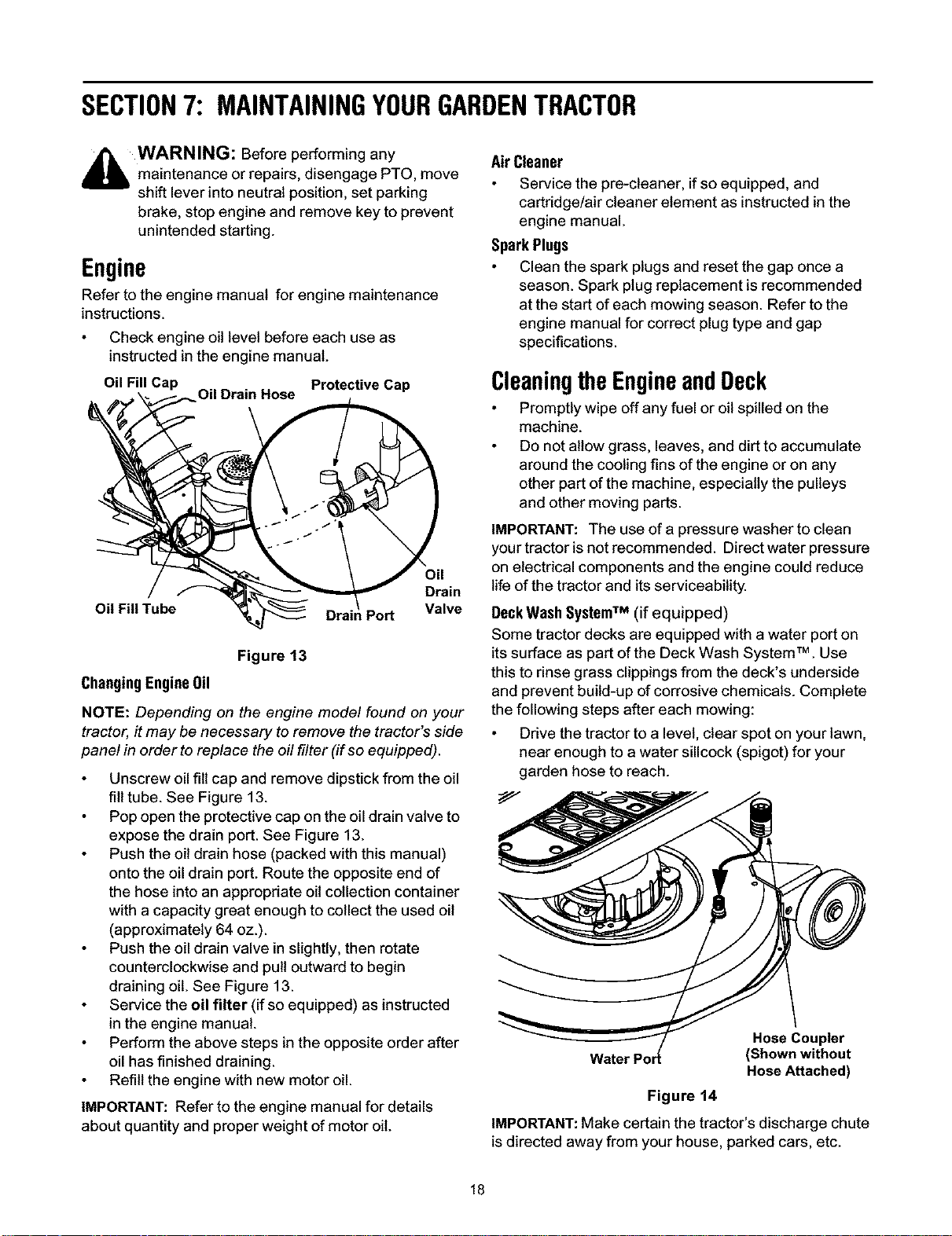
Oil Fill Cap Protective Cap
Oil Fill Tube
Oil
Drain
Valve
Figure 13
ChangingEngine0il
NOTE: Depending on the engine model found on your
tractor, it may be necessary to remove the tractor's side
panel in order to replace the off filter (if so equipped).
Unscrew oil fill cap and remove dipstick from the oil
fill tube. See Figure 13.
Pop open the protective cap on the oil drain valve to
expose the drain port. See Figure 13.
Push the oil drain hose (packed with this manual)
onto the oil drain port. Route the opposite end of
the hose into an appropriate oil collection container
with a capacity great enough to collect the used oil
(approximately 64 oz.).
Push the oil drain valve in slightly, then rotate
counterclockwise and pull outward to begin
draining oil. See Figure 13.
Service the oil filter (if so equipped) as instructed
in the engine manual.
Perform the above steps in the opposite order after
oil has finished draining.
Refill the engine with new motor oil.
IMPORTANT: Refer to the engine manual for details
about quantity and proper weight of motor oil.
AirCleaner
Service the pre-cleaner, if so equipped, and
cartridge!air cleaner element as instructed in the
engine manual.
SparkPlugs
Clean the spark plugs and reset the gap once a
season. Spark plug replacement is recommended
at the start of each mowing season. Refer tothe
engine manual for correct plug type and gap
specifications.
CleaningtheEngineandDeck
Promptly wipe off any fuel or oil spilled on the
machine.
Do not allow grass, leaves, and dirt to accumulate
around the cooling fins of the engine or on any
other part of the machine, especially the pulleys
and other moving parts.
IMPORTANT: The use of a pressure washer to clean
your tractor is not recommended. Direct water pressure
on electrical components and the engine could reduce
life of the tractor and its serviceability.
DeckWashSystemTM (if equipped)
Some tractor decks are equipped with a water port on
itssurface as part of the Deck Wash System TM. Use
this to rinse grass clippingsfrom the deck's underside
and prevent build-up of corrosive chemicals. Complete
the following steps after each mowing:
Drive the tractor to a level, clear spot on your lawn,
near enough to a water sillcock (spigot) for your
garden hose to reach.
Hose Coupler
(Shown without
Hose Attached)
Figure 14
IMPORTANT:Make certain the tractor's discharge chute
is directed away from your house, parked cars, etc.
18
DisengagePTO,moveshiftleverintotheneutral
position,settheparkingbrake,andstopengine.
Threadthehosecoupler(packagedwiththis
manual)ontotheendofyourgardenhose.
Attachthehosecouplertothewaterportonyour
deckssurface.SeeFigure14.
Turnthewateron.
Whilesittingintheoperator'spositiononthe
tractor,re-starttheengineandplacethethrottle
leverintheFAST(rabbit)position.
Engagethetractor'sPTO.
Remainintheoperator'spositionwiththecutting
deckengagedforaminimumoftwominutes,
allowingtheundersideofthecuttingdeckto
throughlyrinse.
Disengagethetractor'sPTO.
TurntheignitionkeytotheSTOPpositiontoturn
thetractor'sengineoff.
Turnthewateroffanddetachthehosecoupler
fromthewaterportonyourdeckssurface.Repeat
step4-11ontheoppositesideofthecuttingdeck.
Lubrication
Engine
WARNING: Before lubricating, repairing, or
inspecting, always disengage PTO, move
shift lever into neutral position, set parking
brake, stop engine and remove key to prevent
unintended starting.
Lubricate the engine with motor oil as instructed in the
Briggs & Stratton Operator/Owner Manual packed with
your unit.
PivotPoints& Linkage
Lubricate all the pivot points on the drive system,
parking brake and lift linkage at least once a season
with light oil.
FrontWheels
Each end of the tractor's front pivot bar is equipped with
a grease fitting. Lubricate with a grease gun after every
25 hours of tractor operation.
SECTION8: SERVICE
CuttingDeckRemoval
To remove the cutting deck, proceed as follows:
Place the PTO knob/lever in the "Blade Stop"
position and engage the parking brake.
Lower the deck by moving the deck lift lever into the
bottom notch on the right fender.
Remove the PTO belt from around the electric PTO
clutch or the engine pulley. Refer to Figure 16.
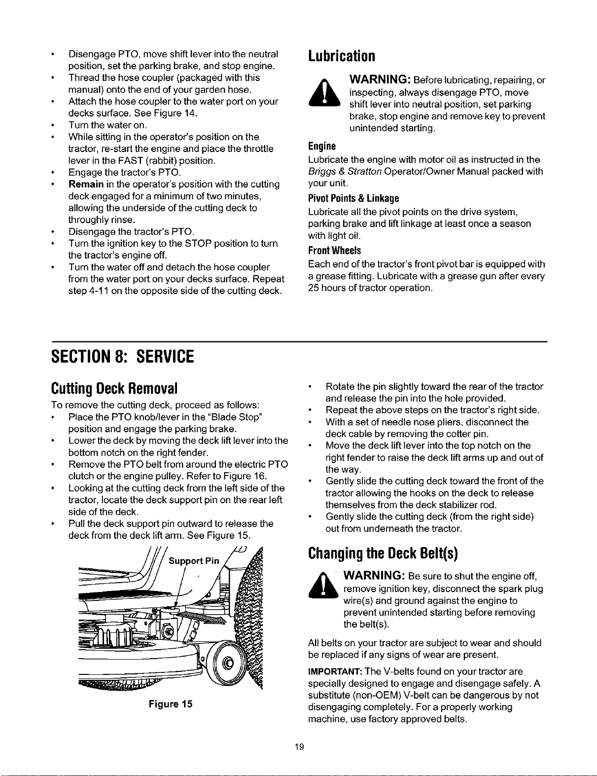
Looking at the cutting deck from the left side of the
tractor, locate the deck support pin on the rear left
side of the deck.
Pull the deck support pin outward to release the
deck from the deck lift arm. See Figure 15.
Figure 15
Rotate the pin slightly toward the rear of the tractor
and release the pin into the hole provided.
Repeat the above steps on the tractor's right side.
With a set of needle nose pliers, disconnect the
deck cable by removing the cotter pin.
Move the deck lift lever intothe top notch on the
right fender to raise the deck lift arms up and out of
the way.
Gently slide the cutting deck toward the front of the
tractor allowing the hooks on the deck to release
themselves from the deck stabilizer rod.
Gently slide the cutting deck (from the right side)
out from underneath the tractor.
ChangingtheDeckBelt(s)
_ WARNING: Be sure to shut the engine off,
remove ignition key, disconnect the spark plug
wire(s) and ground against the engine to
prevent unintended starting before removing
the belt(s).
All belts on your tractor are subject to wear and should
be replaced if any signs of wear are present.
IMPORTANT:The V-belts found on your tractor are
specially designed to engage and disengage safely. A
substitute (non-OEM) V-belt can be dangerous by not
disengaging completely. For a properly working
machine, use factory approved belts.
19
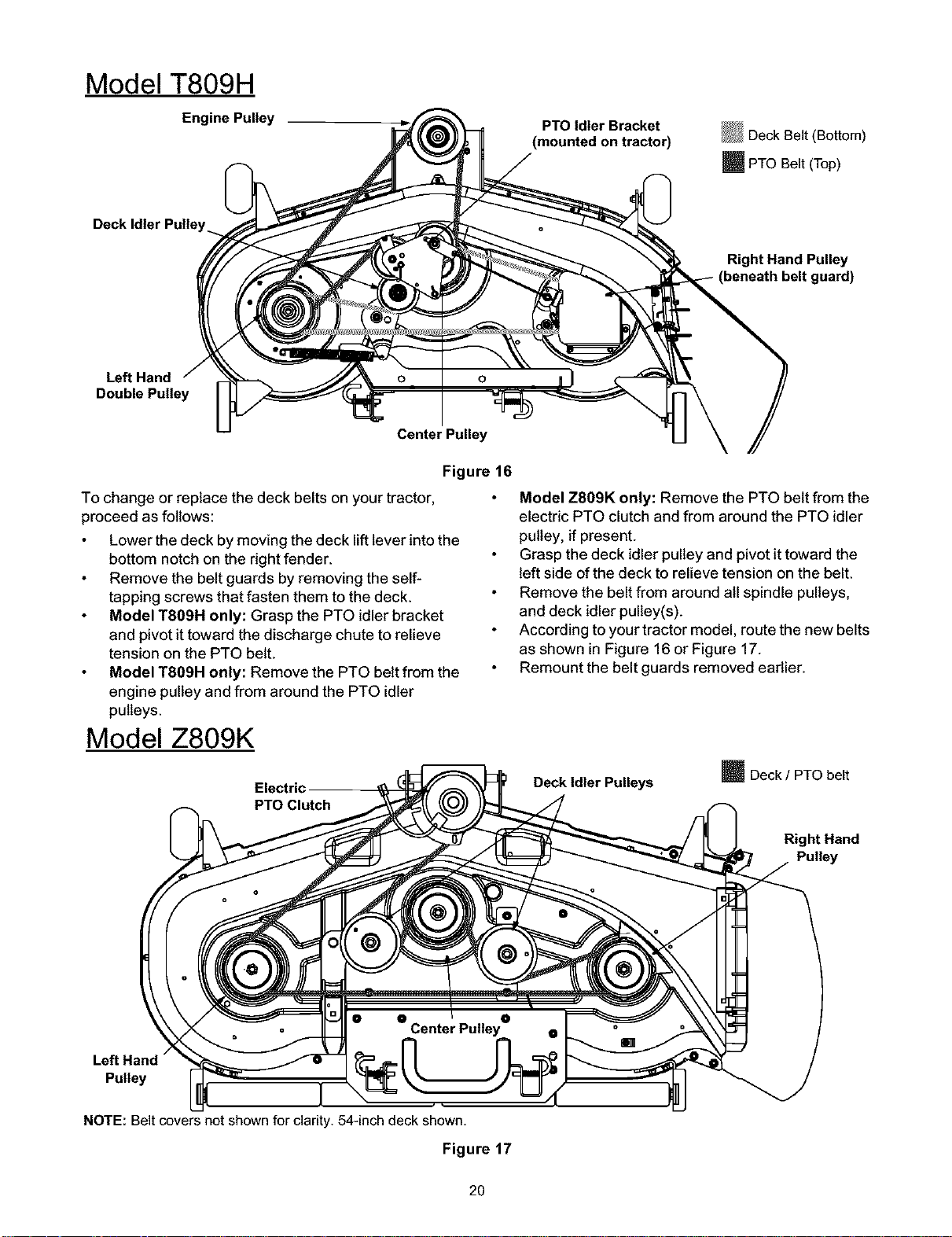
Model T809H
Engine Pulley
PTO Idler Bracket
(mounted on tractor)
_Deck Belt (Bottom)
_PTO Belt (Top)
Right Hand Pulley
guard)
Left Hand
Double Pulley
Center Pulley
Figure 16
To change or replace the deck belts on your tractor,
proceed as fallows:
Lower the deck by moving the deck lift lever into the
bottom notch on the right fender.
Remove the belt guards by removing the self-
tapping screws that fasten them to the deck.
Model T809H only: Grasp the PTO idler bracket
and pivot it toward the discharge chute to relieve
tension on the PTO belt.
Model T809H only: Remove the PTO belt from the
engine pulley and from around the PTO idler
pulleys.
Model Z809K
Electric
PTO Clutch
Model Z809K only: Remove the PTO belt from the
electric PTO clutch and from around the PTO idler
pulley, if present.
Grasp the deck idler pulley and pivotit toward the
left side of the deck to relieve tension on the belt.
Remove the belt from around all spindle pulleys,
and deck idler pulley(s).
According to your tractor model, route the new belts
as shown in Figure 16 or Figure 17.
Remount the belt guards removed eadier.
Deck Idler Pulleys
m Deck / PTO belt
Right Hand
Pulley
Left Hand
Pulley
NOTE: Belt covers not shown for clarity. 54-inch deck shown.
Figure 17
2O
ChangingtheTransmissionDriveBelt
,_ WARNING: Be sure to shut the engine off,
remove ignition key, disconnect the spark plug
wire(s) and ground against the engine to
prevent unintended starting before removing
the belt(s).
All belts on your tractor are subject to wear and should
be replaced if any signs of damage are observed.
NOTE: It is recommended that both drive belts be
replaced at the same time.
IMPORTANT: The V-belts found on your tractor are
specially designed to engage and disengage safely. A
substitute (non-OEM) V-belt can be dangerous by not
disengaging completely. For a proper working machine,
use factory approved belts.
To change or replace the drive belt on your tractor,
proceed as follows:
Remove the cutting deck as instructed earlier.
After disconnecting the battery cables, remove the
battery and battery tray from beneath the seat.
IMPORTANT: When removing the battery, disconnect
the negative (black) wire from its terminal first, followed
by the positive (red) wire. Re-install in reverse order.
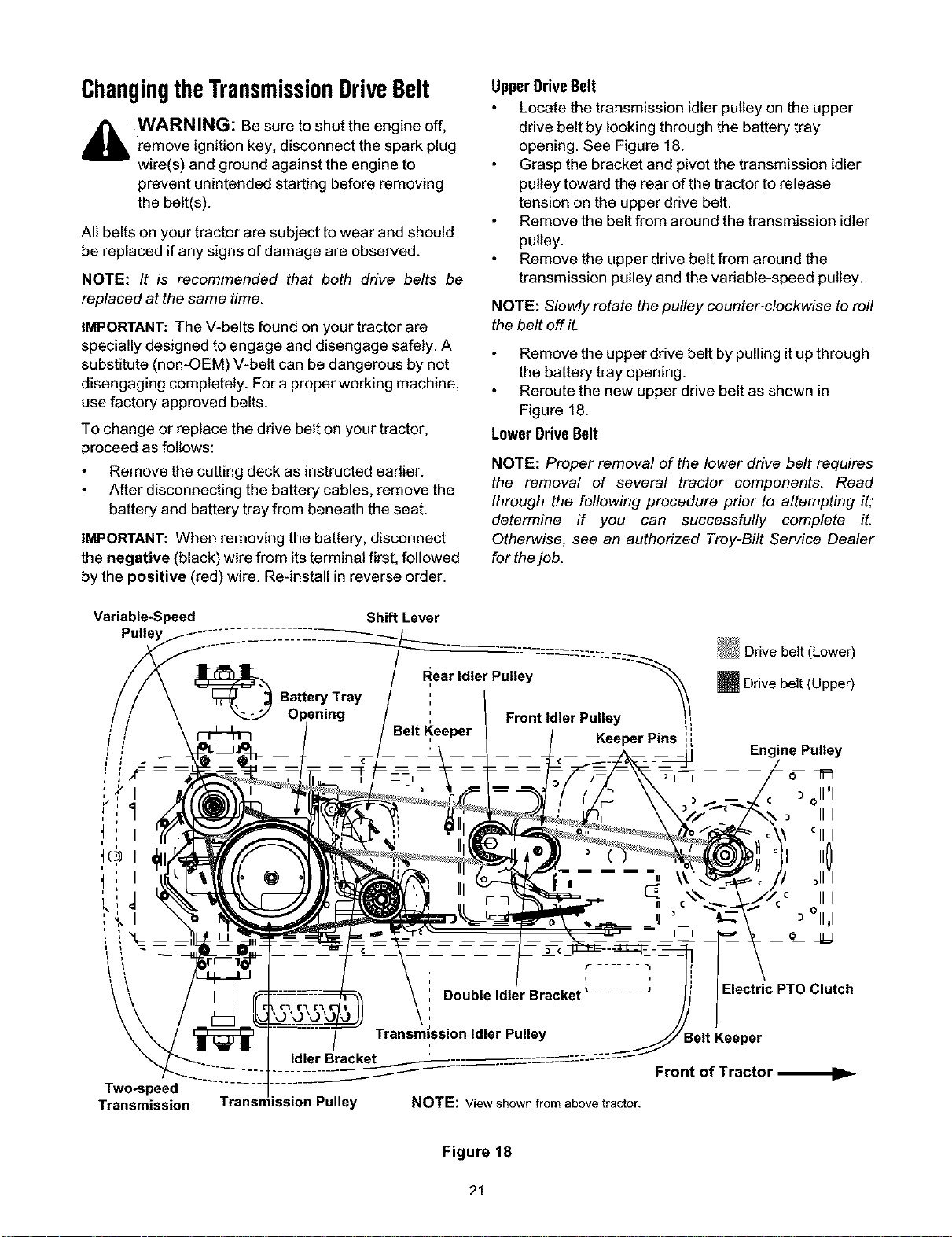
UpperDriveBelt
Locate the transmission idler pulley on the upper
drive belt by looking through the battery tray
opening. See Figure 18.
Grasp the bracket and pivot the transmission idler
pulley toward the rear of the tractor to release
tension on the upper drive belt.
Remove the belt from around the transmission idler
pulley.
Remove the upper drive belt from around the
transmission pulley and the variable-speed pulley.
NOTE: Slowly rotate the pulley counter-clockwise to roll
the belt off it.
Remove the upper drive belt by pulling it up through
the battery tray opening.
Reroute the new upper drive belt as shown in
Figure 18.
LowerDriveBelt
NOTE: Proper removal of the lower drive belt requires
the removal of several tractor components. Read
through the following procedure prior to attempting it;
determine if you can successfully complete it.
Otherwise, see an authorized Troy-Bilt Service Dealer
for the job.
Variable*Speed Shift Lever
ear Idler Pulley ::'--'\'::::'_
: Front Idler Pulley Ii
KeeperPins ',',
m Drive belt (Upper)
Engine Pulley
5-_=_
o11'1
III
till
I101
_111
.c III
°11,1
o _=j
Electric PTO Clutch
Two-speed
Transmission
Transmission Pulley
Front of Tractor
NOTE: View shown from above tractor,
Figure 18
21
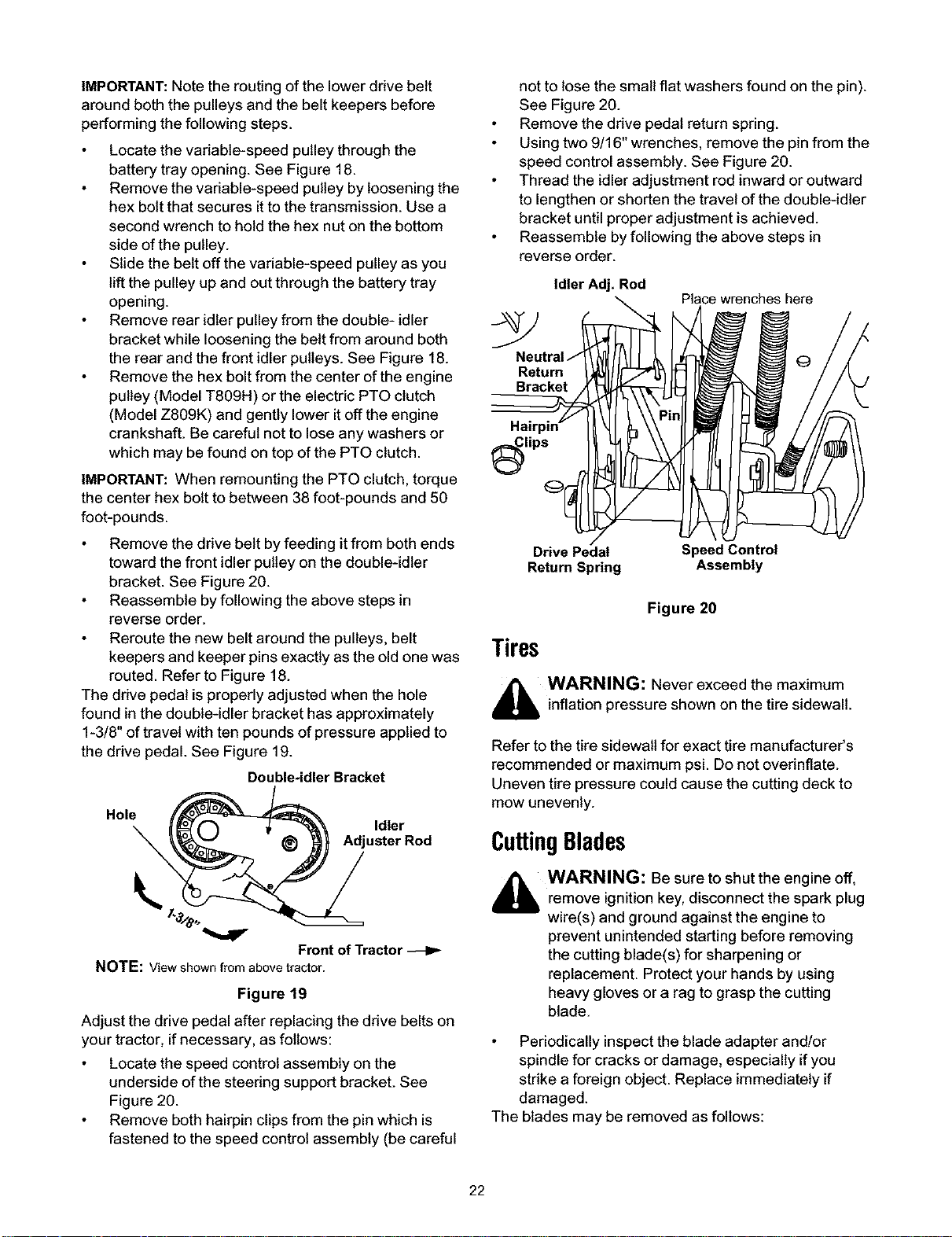
IMPORTANT: Note the routing of the lower drive belt
around both the pulleys and the belt keepers before
performing the following steps.
Locate the variable-speed pulley through the
battery tray opening. See Figure 18.
Remove the variable-speed pulley by loosening the
hex bolt that secures itto the transmission. Use a
second wrench to hold the hex nut on the bottom
side of the pulley.
Slide the belt off the variable-speed pulley as you
lift the pulley up and out through the battery tray
opening.
Remove rear idler pulley from the double- idler
bracket while loosening the belt from around both
the rear and the front idler pulleys. See Figure 18.
Remove the hex bolt from the center of the engine
pulley (Model T809H) or the electric PTO clutch
(Model Z809K) and gently lower it off the engine
crankshaft. Be careful not to lose any washers or
which may be found on top of the PTO clutch.
IMPORTANT: When remounting the PTO clutch, torque
the center hex bolt to between 38 foot-pounds and 50
foot-pounds.
Remove the drive belt by feeding itfrom both ends
toward the front idler pulley on the double-idler
bracket. See Figure 20.
Reassemble by following the above steps in
reverse order.
Reroute the new belt around the pulleys, belt
keepers and keeper pins exactly as the old one was
routed. Refer to Figure 18.
The drive pedal is properly adjusted when the hole
found in the double-idler bracket has approximately
1-3/8" of travel with ten pounds of pressure applied to
the drive pedal. See Figure 19.
Double-idler Bracket
.o,e\ Adju"' rRod
Front of Tractor
NOTE: Viewshownfromabovetractor.
Figure 19
Adjust the drive pedal after replacing the drive belts on
your tractor, ifnecessary, as follows:
Locate the speed control assembly on the
underside of the steering support bracket. See
Figure 20.
Remove both hairpin clips from the pin which is
fastened to the speed control assembly (be careful
not to lose the small flat washers found on the pin).
See Figure 20.
Remove the drive pedal return spring.
Using two 9/16" wrenches, remove the pin from the
speed control assembly. See Figure 20.
Thread the idler adjustment rod inward or outward
to lengthen or shorten the travel of the double-idler
bracket until proper adjustment is achieved.
Reassemble by following the above steps in
reverse order.
Idler Adj. Rod
Place wrenches here
Return
Bracket
lips
Drive Pedal
Return Spring
Speed Control
Assembly
Figure 20
Tires
,_ WARNING: Never exceed the maximum
inflation pressure shown on the tire sidewall.
Refer to the tire sidewall for exact tire manufacturer's
recommended or maximum psi. Do not overinflate.
Uneven tire pressure could cause the cutting deck to
mow unevenly.
CuttingBlades
_b WARNING: Be sure to shut the engine off,
remove ignitionkey, disconnect the spark plug
wire(s) and ground against the engine to
prevent unintended starting before removing
the cutting blade(s) for sharpening or
replacement. Protect your hands by using
heavy gloves or a rag to grasp the cutting
blade.
Periodically inspectthe blade adapter and!or
spindle for cracks or damage, especially ifyou
strike a foreign object. Replace immediately if
damaged.
The blades may be removed as follows:
22
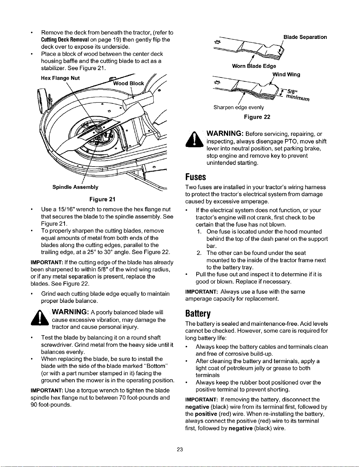
Remove the deck from beneath the tractor, (refer to
CtrttingDeckRemovalon page 19) then gently flip the
deck over to expose itsunderside.
Place a block of wood between the center deck
housing baffle and the cutting blade to act as a
stabilizer. See Figure 21.
Hex Flange Nut
Spindle Assembly
Figure 21
Use a 15/16" wrench to remove the hex flange nut
that secures the blade to the spindle assembly. See
Figure 21.
To properly sharpen the cutting blades, remove
equal amounts of metal from both ends of the
blades along the cutting edges, parallel to the
trailing edge, at a 25° to 30° angle. See Figure 22.
IMPORTANT: If the cutting edge of the blade has already
been sharpened to within 5/8" of the wind wing radius,
or if any metal separation is present, replace the
blades. See Figure 22.
Grind each cutting blade edge equally to maintain
proper blade balance.
_ WARNING: A poorlybalanced blade wilt
cause excessive vibration, may damage the
tractor and cause personal injury.
Test the blade by balancing it on a round shaft
screwdriver. Grind metal from the heavy side until it
balances evenly.
When replacing the blade, be sure to install the
blade with the side of the blade marked "Bottom"
(or with a part number stamped in it)facing the
ground when the mower is inthe operating position.
IMPORTANT: Use a torque wrench to tighten the blade
spindle hex flange nut to between 70 foot-pounds and
90 foot-pounds.
Worn I_lade
Blade Separation
Edge
Wind Wing
Sharpen edge evenly
Figure 22
,_ WARNING: Before servicing, repairing, or
inspecting, always disengage PTO, move shift
lever into neutral position, set parking brake,
stop engine and remove key to prevent
unintended starting.
Fuses
Two fuses are installed in your tractor's wiring harness
to protect the tractor's electrical system from damage
caused by excessive amperage.
If the electrical system does not function, or your
tractor's engine will not crank, first check to be
certain that the fuse has not blown.
1. One fuse is located under the hood mounted
behind the top of the dash panel on the support
bar.
2. The other can be found under the seat
mounted to the inside of the tractor frame next
to the battery tray.
Pull the fuse out and inspect it to determine if it is
good or blown. Replace if necessary.
IMPORTANT: Always use a fuse with the same
amperage capacity for replacement.
Battery
The battery issealed and maintenance-free. Acid levels
cannot be checked. However, some care is required for
long battery life:
Always keep the battery cables and terminals clean
and free of corrosive build-up.
After cleaning the battery and terminals, apply a
light coat of petroleum jelly or grease to both
terminals
Always keep the rubber boot positioned over the
positive terminal to prevent shorting.
IMPORTANT: If removing the battery, disconnect the
negative (black) wire from its terminal first, followed by
the positive (red) wire. When re-installing the battery,
always connect the positive (red) wire to its terminal
first, followed by negative (black) wire.
23
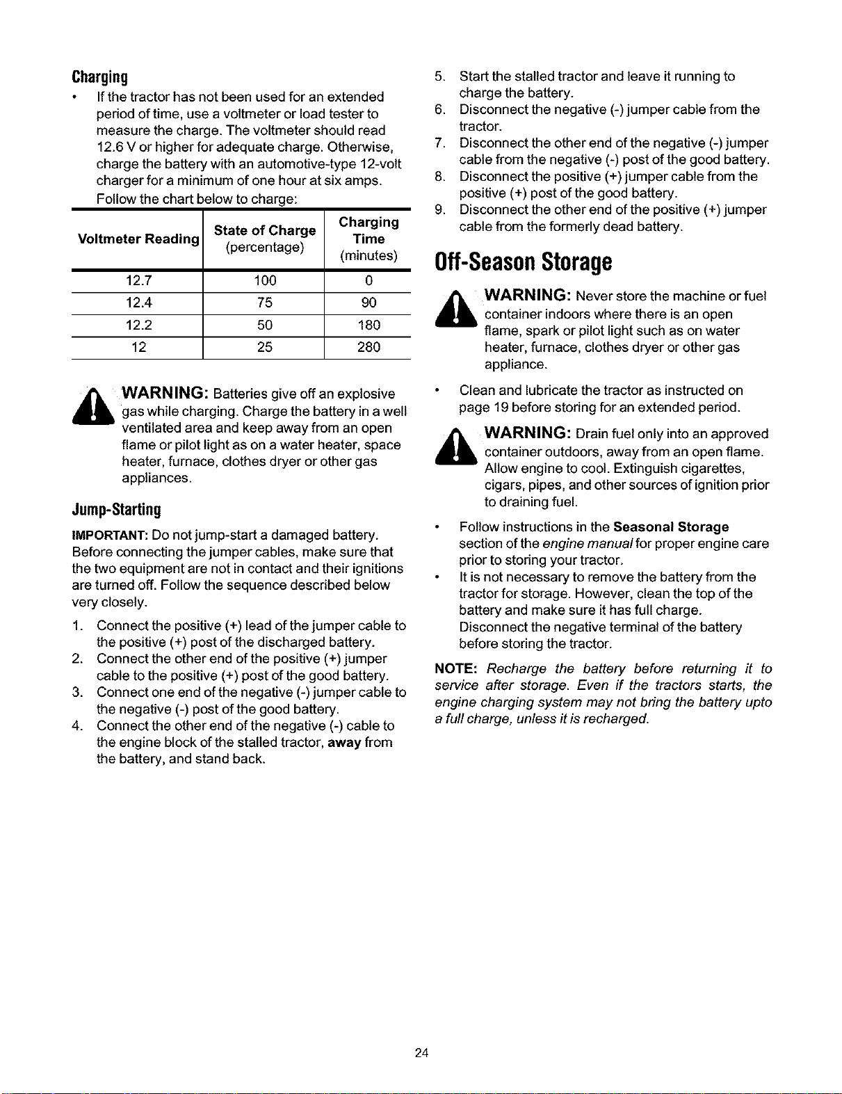
Charging
If the tractor has not been used for an extended
period of time, use a voltmeter or load tester to
measure the charge. The voltmeter should read
12.6 V or higher for adequate charge. Otherwise,
charge the battery with an automotive-type 12-volt
charger for a minimum of one hour at six amps.
Follow the chart below to charge:
Voltmeter Reading
12.7
12.4
12.2
12
State of Charge
(percentage)
100
75
5O
25
Charging
Time
(minutes)
0
9O
180
280
,_ WARNING: Batteries give off an explosive
gas while charging. Charge the battery in a well
ventilated area and keep away from an open
flame or pilot light as on a water heater, space
heater, furnace, clothes dryer or other gas
appliances.
Jump-Starting
IMPORTANT: Do not jump-start a damaged battery.
Before connecting the jumper cables, make sure that
the two equipment are not in contact and their ignitions
are turned off. Follow the sequence described below
very closely.
1. Connect the positive (+) lead of the jumper cable to
the positive (+) post of the discharged battery.
2. Connect the other end of the positive (+) jumper
cable to the positive (+) post of the good battery.
3. Connect one end of the negative (-) jumper cable to
the negative (-) post of the good battery.
4. Connect the other end of the negative (-) cable to
the engine block of the stalled tractor, away from
the battery, and stand back.
5. Start the stalled tractor and leave it running to
charge the battery.
6. Disconnect the negative (-) jumper cable from the
tractor.
7. Disconnect the other end of the negative (-) jumper
cable from the negative (-) post of the good battery.
8. Disconnect the positive (+) jumper cable from the
positive (+) post of the good battery.
9. Disconnect the other end of the positive (+) jumper
cable from the formerly dead battery.
Off-SeasonStorage
_ WARNING: Never store the machine or fuel
container indoors where there is an open
flame, spark or pilot light such as on water
heater, furnace, clothes dryer or other gas
appliance.
Clean and lubricate the tractor as instructed on
page 19 before storing for an extended pedod.
_ WARNING: Drain fuel only intoan approved
container outdoors, away from an open flame.
Allow engine to cool. Extinguish cigarettes,
cigars, pipes, and other sources of ignition prior
to draining fuel.
Follow instructions in the Seasonal Storage
section of the engine manua/for proper engine care
prior to storing your tractor.
It is not necessary to remove the battery from the
tractor for storage. However, clean the top of the
battery and make sure it has full charge.
Disconnect the negative terminal of the battery
before storing the tractor.
NOTE: Recharge the battery before returning it to
service after storage. Even if the tractors starts, the
engine charging system may not bring the battery upto
a full charge, unless it is recharged.
24

SECTION9: ATTACHMENTS&ACCESSORIES
The following attachments and accessories are compatible for tractor Models Z809H & Z809K. See the retailer
from which you purchased your tractor or phone (866) 840-6483 for information regarding price and availability.
MODEL
OEM-190-118
OEM-190-603
OEM-190-604
OEM-190-607
OEM-190-608
OEM-190-821
OEM-190-822
OEM-190-823
OEM-190-824
OEM-190-841
OEM-190-842
DESCRIPTION
Mulch Kit (For 46-inch Decks Only)
FastAttach TM Grille Guard (mounts on front of tractor)
FastAttach TM Yard-Mate TM Storage Container/Toolbox (mounts on rear of tractor)
FastAttach TM Deluxe Tractor Sunshade
FastAttach TM Sleeve Hitch, Manual Lift
FastAttach TM Triple Bagger Grass Collector (For 46-inch Decks Only)
FastAttach TM 46-inch Front Dozer Blade
42-inch Two-stage Snowthrower
Sleeve Hitch with Electric Lift
Mulch Kit (For 54-inch Decks Only)
FastAttach TM Triple Bagger Grass Collector (For 54-inch Decks Only)
OEM-190-825
OEM-190-984
OEM-190-980
OEM-190-978
OEM-190-804
SLEEVE HITCH ATTACHMENTS (For use with OEM-190-824 or OEM-190-608 )
30-inch Hydraulic Tiller1"
Row Crop Cultivator
Single-disc Harrow
10-inch Mulboard Plow
42- nch Heavy Duty Rear Bade
1"OEM-190-824 is required for use of this attachment. OEM-190-608 cannot be used in its place.
25

SECTION10: TROUBLESHOOTING
Trouble Corrective Action
Engine fails to start
Engine runs erratic
Possible Cause(s)
PTO knob engaged.
Parking brake not engaged.
Spark plug wire(s) disconnected.
Throttle control lever not in correct
starting position.
Choke not activated
Fuel tank empty, or stale fuel.
Blocked fuel line.
Faulty spark plug.
Engine flooded.
Unit running with CHOKE applied.
Spark plug wire(s) loose.
Blocked fuel line or stale fuel.
Vent in gas cap plugged.
Water or dirt in fuel system.
Dirty air cleaner.
Engine oil level low.
Air flow restricted.
Place PTO knob in disengaged (OFF) position.
Engage parking brake.
Connect wire(s) to spark plug.
Place throttle lever to FAST position.
Pull out the CHOKE control (if so equipped).
Fill tank with clean, fresh (less than 30 days old) gas.
Clean fuel line or replace fuel filter, if so equipped.
Clean, adjust gap or replace plug.
Crank engine with throttle in FAST position.
Push CHOKE control (if so equipped) in.
Connect and tighten spark plug wire(s).
Clean fuel line; fill tank with clean, fresh (less than 30
days old) gasoline. Replace fuel filter, if so equipped.
Clear vent or replace cap if damaged.
Drain fuel tank. Refill with clean, fresh (less than 30
days old) gasoline.
Replace air cleaner cartridge/element or clean pre-
cleaner, if so equipped.
Fill crankcase with proper capacity and weight of oil.
Clean grass clippings and debris from around the
engine's cooling fins and blower housing.
Remove spark plug(s) and reset the gap to .030".
Replace spark plug(s). Set plug(s) gap to .030".
Engine overheats
Engine hesitates at high RPM Spark plug(s) gap too close.
Idles poorly Spark plug(s) fouled, faulty or gap too
wide.
Dirty air cleaner. Replace air cleaner cartridge/element or clean pre-
cleaner, if so equipped.
Excessive vibration Cutting blade loose or unbalanced. Tighten blade and spindle. Balance blade.
Damaged or bent cutting blade. Replace blade.
Mower will not mulch grass Engine speed too low. Place throttle in FAST (rabbit) position.
Wet grass. Do not mow when grass is wet; wait until later to cut.
Excessively high grass. Mow once at a high cutting height, then mow again at
desired height or make a narrower cutting swath.
Dull blade. Sharpen or replace blade.
Uneven cut Deck not balanced properly. Perform side-to-side deck adjustment.
Dull blade. Sharpen or replace blade.
Uneven tire pressure. Check tire pressure in all four tires.
26
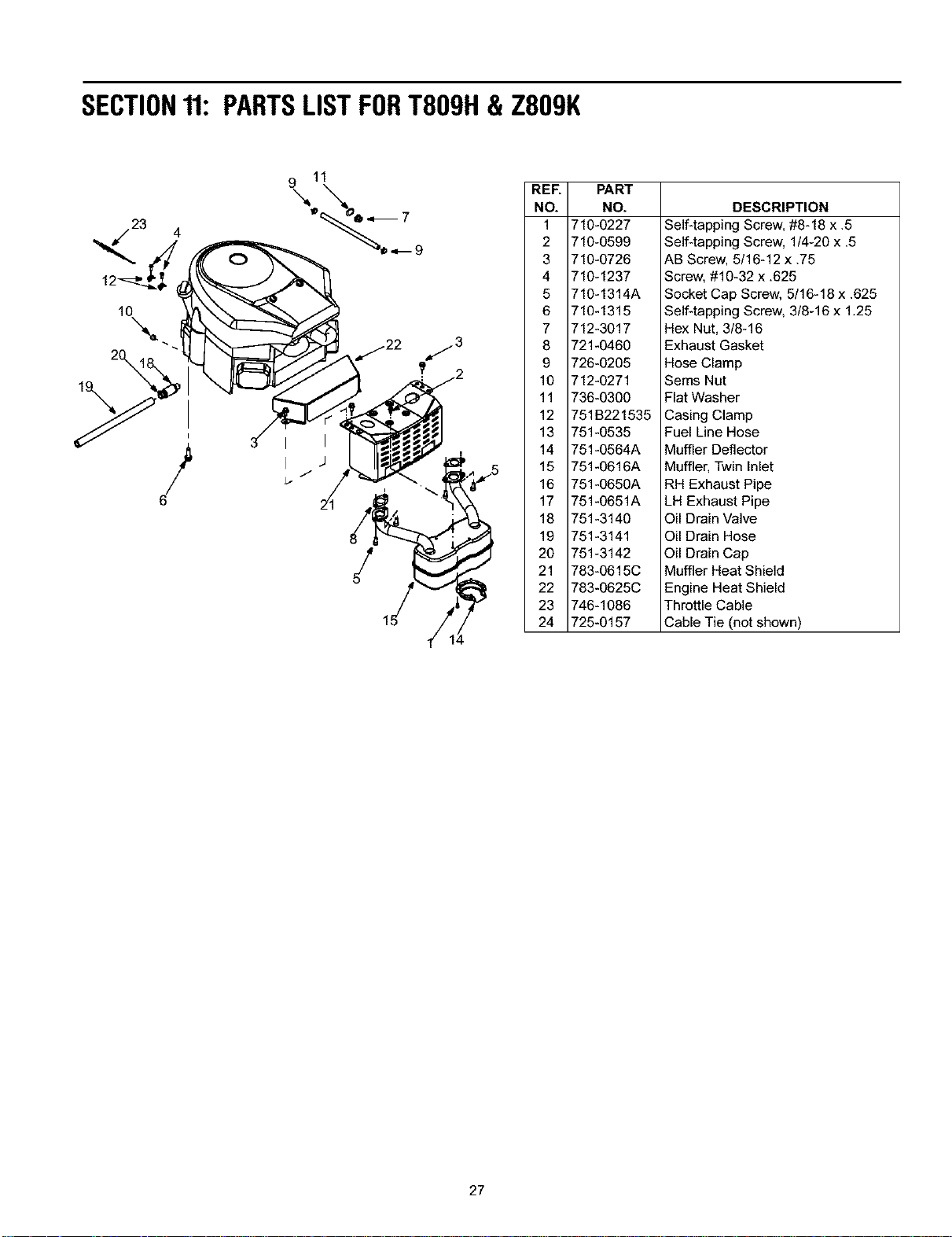
SECTION11:PARTSLISTFORT809H& Z809K
10
\
I
I
REF.
NO.
1
2
3
4
5
6
7
8
9
10
11
12
13
14
15
16
17
18
19
2O
21
22
23
24
PART
NO.
710-0227
710-0599
710-0726
710-1237
710-1314A
710-1315
712-3017
721-0460
726-0205
712-0271
736-0300
751B221535
751-0535
751-0564A
751-0616A
751-0650A
751-0651A
751-3140
751-3141
751-3142
783-0615C
783-0625C
746-1086
725-0157
DESCRIPTION
Self-tapping Screw, #8-18 x .5
Self-tapping Screw, 1/4-20 x .5
AB Screw, 5/16-12 x .75
Screw, #10-32 x .625
Socket Cap Screw, 5/16-18 x .625
Self-tapping Screw, 3/8-16 x 1.25
Hex Nut, 3/8-16
Exhaust Gasket
Hose Clamp
Sems Nut
Flat Washer
Casing Clamp
Fuel Line Hose
Muffler Deflector
Muffler, Twin Inlet
RH Exhaust Pipe
LH Exhaust Pipe
Oil Drain Valve
Oil Drain Hose
Oil Drain Cap
Muffler Heat Shield
Engine Heat Shield
Throttle Cable
Cable Tie (not shown)
27
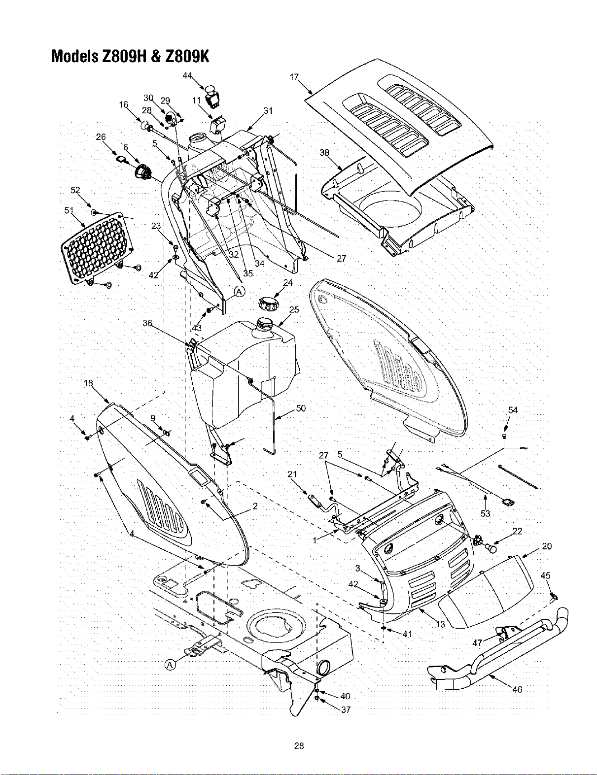
ModelsZ809H&Z809K
17
26
\
24
21
2
54
28

ModelsT809H&Z809K
*Not standard on all tractors.
REF.
NO.
1
2
3
4
5
6
7
8
9
10
11
12
13
15
16
17
18
19
2O
21
22
23
24
25
26
27
28
29
30
31
32
33
34
35
36
37
38
39
40
41
42
43
44
45
46
47
48
49
50
51
52
53
54
PART
NO.
783-1346
710-0599
710-0528
710-0924
710-1017
725-1741
726-0272
710-0642
712-0292
736-0270
725-1976
725-04036A
712-3004A
731-2119A
725-0175
746-1085A
783-0783
783-0784
783-04200
731-2637
747-2138
625-0051
710-0726
751-0603
751-3213A
725-1745
725-1744
710-0895
710-3217
712-0142
731-1857
731-2225C
731-04215
731-04217
736-0142
747-1196
783-04285
783-04383
712-3010
731-2270
726-3046
736-0119
726-0201
736-3078
710-0650
725-1752
711-0332
768-0010
714-0145
710-1611B
735-04019
747-04132
735-04023
726-3046
629-04083
629-04073
DESCRIPTION
Grill Support Bracket (9-style)
Self-tapping Screw, 1/4-20 x .5
Hex Cap Screw, 5/16-18 x 1.25
Phillips Pan Screw, 1/4-20 x .75
Truss Phillips Screw, 1/4-20 x .625
Ignition Switch
Clamp, 9/16
Self-tapping Screw, 1/4-20 x .75
U-type Speed Nut, 1/4-20
Bell Washer, .265 x .75 x .062
Systems Indicator Monitor
Hour Meter
Hex Nut, 5/16-18
Grille (9-style)
Cable Tie, 3/16 x .05 x 7.4
Choke Knob/Cable
Hood (9-style)
RH Side Panel
LH Side Panel
Headlight Lens
Hood Hinge Rod
Headlight Assembly
AB Screw, 5/16-12 x .75
Fuel Cap
Fuel Tank, 3 gallon
Ignition Key w/plastic cover
Ignition Key w/o plastic cover
Self-tapping Screw, 1/4-15 x .75
Truss Phillips Screw, #8-32 x .375
Hex Nut, #8-32
Throttle Control Knob
Dash Panel, 8/9-style, Electric PTO
Cruise Control Button
Parking Brake Button
Flat Washer, 9/32 x 1/2 x 1/16
Brake/Cruise Pivot Rod
Dash Support Plate RH
Dash Support Plate LH
Hex Nut, 5/16-18
Hood Plenum*
Ratchet Clip
Lock Washer, 5/16
Speed Nut, .3125
Flat Washer, .349 x 1.0 x .063
TT Screw, 5/16-18 x .875
Electric PTO Switch
Clevis Pin, .50 x .78
Bumper Assembly
Click Pin
TT Screw 5/16-18 x 0.75
Seal: Panel
Tank Support Rod
Cargo Net
Ratchet Clip
Headlight Wire Harness
Tractor Wire Harness
29
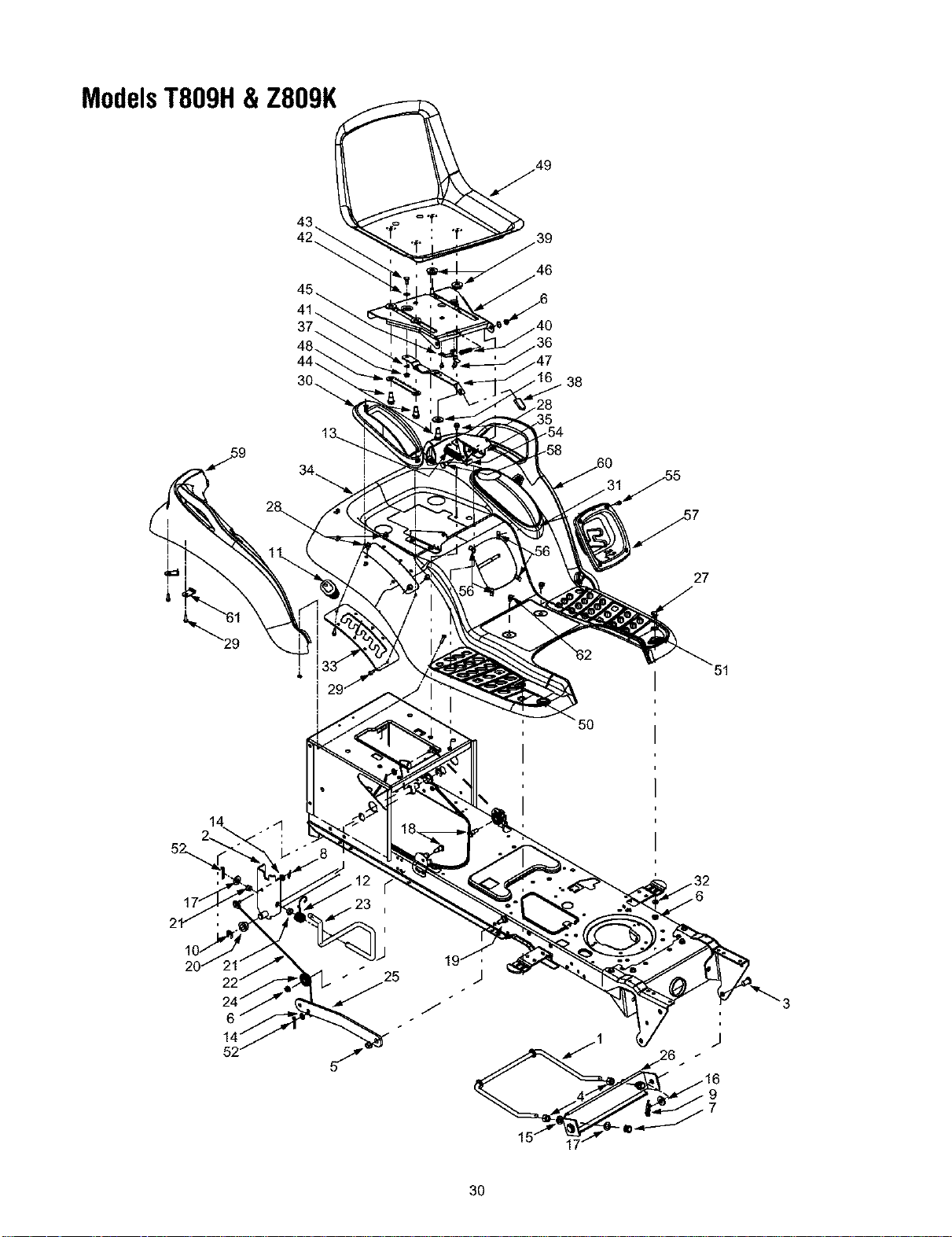
ModelsT809H& Z809K
46
38
27
14 .,d
'3
3O

ModelsT809H& Z809K
REE PART
NO. NO.
1 747-1130B
747-1324
2 683-0197B
683-0462
3 711-0332
4 712-0206
5 712-0431
6 712-0429
7 712-3083
8 714-0104
9 714-0145
10 716-0106A
11 720-0311
12 732-0874
13 732-1184
14 736-0275
15 736-0921
16 736-3019
17 736-3084
18 738-0138A
19 738-0143
20 741-0225
21 741-0715
22 746-0968
23 747-1111A
24 756-1154
25 783-0678A
26 783-0720A
27 710-0260A
28 710-0726
29 710-0895
30 731-1990
DESCRIPTION
Deck Stabilizer Rod (Model T809H)
Deck Stabilizer Rod (Model ZS09K)
Lift Shaft Assembly (Model T809H)
Lift Shaft Assembly (Model Z809K)
Clevis Pin, .5 x .78
Hex Nut, 1/2-13
Flange Lock Nut, 3/8-16
Lock Nut, 5/16-18
Hex Nut, 1/2-13
Internal Cotter Pin
Internal Cotter Pin
E-Ring
Handle Grip
Torsion Spring
Extension Spring, .84 x 4.6
Flat Washer, 5/16
Lock Washer, 1/2
Flat Washer, .31 x 1.062 x .134
Flat Washer, .51 x 1.12 x .06
Hex Cap Screw, 5/16-18 x .62
Shoulder Screw, 3/8-16
Hex Flange Bearing
Snap Flange Bearing
Lift Cable. 16.16
Lift Handle
Roller Pulley
Arm Lift
Deck Stabilizer Bracket
Carriage Bolt, 5/16 x .62
AB Screw. 5/16-12 x .75
Self-tapping Screw. 1/4-15 x .75
Lift Lever Cover
REF.
NO.
31
32
33
34
35
36
37
38
39
40
41
42
43
44
45
46
47
48
49
50
51
52
54
55
56
57
58
59
66
61
62
PART
NO.
731-1993
736-3078
783-0677
783-04331
783-1489
710-1268
712-3027
720-0309A
731-04074
732-0499
736-0275
736-0204
738-0137A
738-1007
783-0611
783-0738
783-0739
783-0753
757-04010
735-0656
735-0657
726-3046
714-0111
783-0209C
710-0924
712-0292
731-2480
738-0296
731-2618
731-2619
783-1478
710-0599
DESCRIPTION
Cover w/Cup Holder
Flat Washer, .349 x 1.0 x .063
Lift Adjustment Bracket
Fender
Seat Mounting Bracket
Screw, #10-16 x .375
Hex Flange Lock Nut, 1/4-20
Seat Adjuster Grip
Spacer
Compression Spring, .41 x 1.5
Spring Washer, .265 x .562 x .025
Flat Washer, .344 x .62 x .03
Shoulder Screw, .340 x .285.1/4-20
Shoulder Screw..50 x .50, 3/8-16
Seat Stop
Seat Pivot Bracket
Seat Adjustment Lever
Seat Adjustment Selector
High Back Seat. Black
RH Foot Pad
LH Foot Pad
Foot Pad Clips
Cotter Pin
Seat Lift Bracket
Phillips Pan Screw, 1/4-20 x .75
U-type Speed Nut, 1/4-20
Shift Lever Cover
Shoulder Screw, .437 x .286
RH Fender Flare
LH Fender Flare
Fender Clips
TT Screw 1/4-20 x 0.5
31
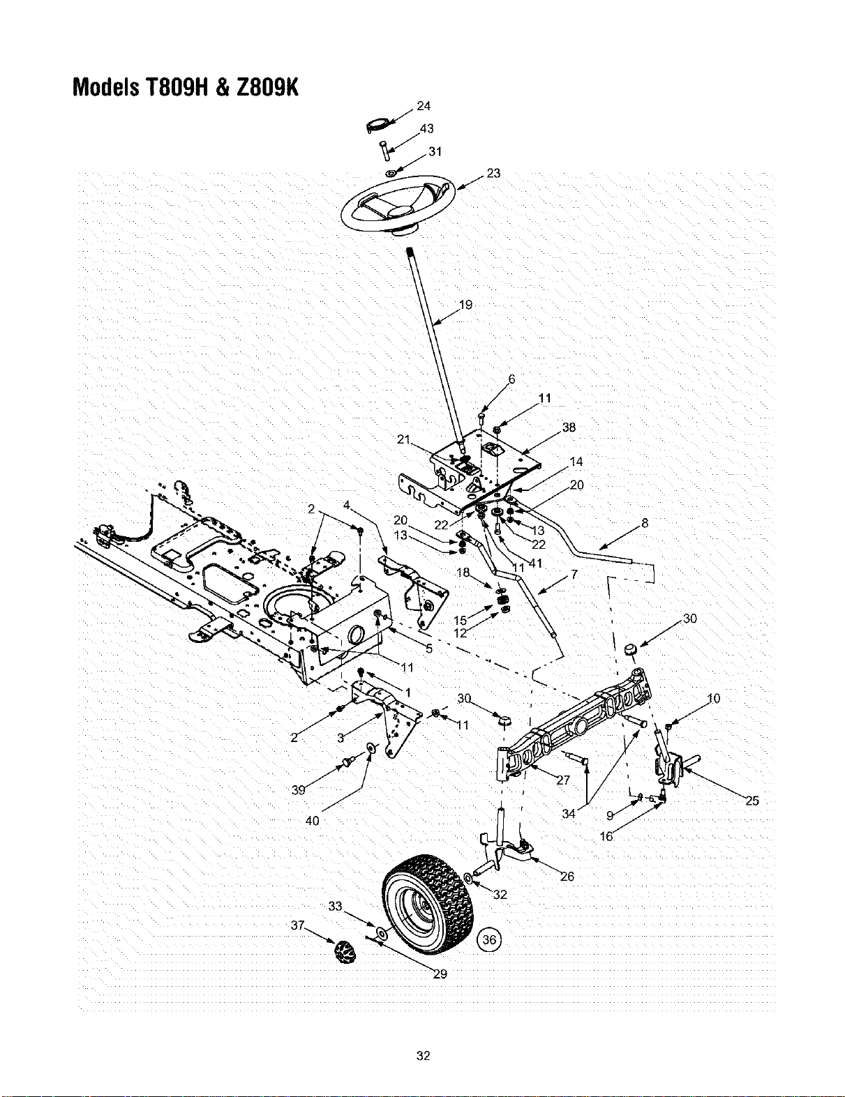
ModelsT809H& Z809K
11
/38
/
14
/
.20
/7
/30
/
4O
/
34/
"29
"26
32

ModelsT809H&Z809K
REF.
NO.
1
2
3
4
5
6
7
8
9
10
11
12
13
14
15
16
17
18
19
20
21
22
23
24
25
26
27
29
30
31
32
33
34
35
36
37
38
39
40
41
PART
NO.
710-1260A
710-0604A
783-0726B
783-0727A
783-0728
710-0514
711-1408
711-1409A
712-0240
712-0214
712-0130
712-0459
712-3004A
717-1550E
717-1554
723-0448A
736-0169
736-3084
738-1001A
741-0475
741-0656
738-0372B
731-04008
731-04066
638-04003
638-04004
719-0525C
714-0162
726-0341
736-0242
736-0316
736-0285
738-1011
710-0643
634-04088
634-04082
734-0255
734-1727
741-0516A
741-0990A
734-2290A
783-0653E
738-0143
736-0331
710-04095
DESCRIPTION
Self-tapping Screw, 5/16-18 x .75
Self-tapping Screw, 16-18 x .625
RH Pivot Support Bracket
LH Pivot Support Bracket
Pivot Bar Bracket
Hex Cap Screw, 3/8-16 x 1
RH Drag Link
LH Drag Link
Jam Nut, 7/16-20
Hex Nut, 3/8-24
Lock Nut, 3/8-16
Flange Lock Nut, 7/16-20
Flange Lock Nut, 5/16-18
Steering Gear, 11/90 Ratio
Steering Pinion Gear
Ball Joint, 7/16-20
Lock Washer, 3/8
Flat Washer, .51 x 1.12 x .06
Steering Shaft, .625 OD x 24.4
Plastic Bushing, .38 ID
Hex Flange Bearing, 5/8
Shoulder Spacer, .38 ID
Steering Wheel, Soft Grip, Three Spoke
Steering Wheel Cap, Round
LH Axle Assembly, .75 Diameter
RH Axle Assembly, .75 Diameter
Cast Iron Pivot Bar w/Fittings, .75
Cotter Pin
Push Cap, .750
Bell Washer, .34 x .872
Flat Washer, .78 x 1.59 x .06
Flat Washer, .635 x 1.589 x .06
Shoulder Screw, .5 x 2.2, 3/8-16
Hex Bolt, 5/16-18 X 1
Wheel Assembly Complete, 16 x 6.5 x 8
Rim Only w/Plastic Bearing
Air Valve (Not Shown)
Tire Only, Square Shoulder
Flange Bearing
Flange Bearing w/Grease Fitting
Hub Cap
Steering Support Bracket
Shoulder Screw, 3/8-16
Bell Washer, .39 x 1.13 x .062
Hex Bolt 3/8-16 x 1.0 Special
33
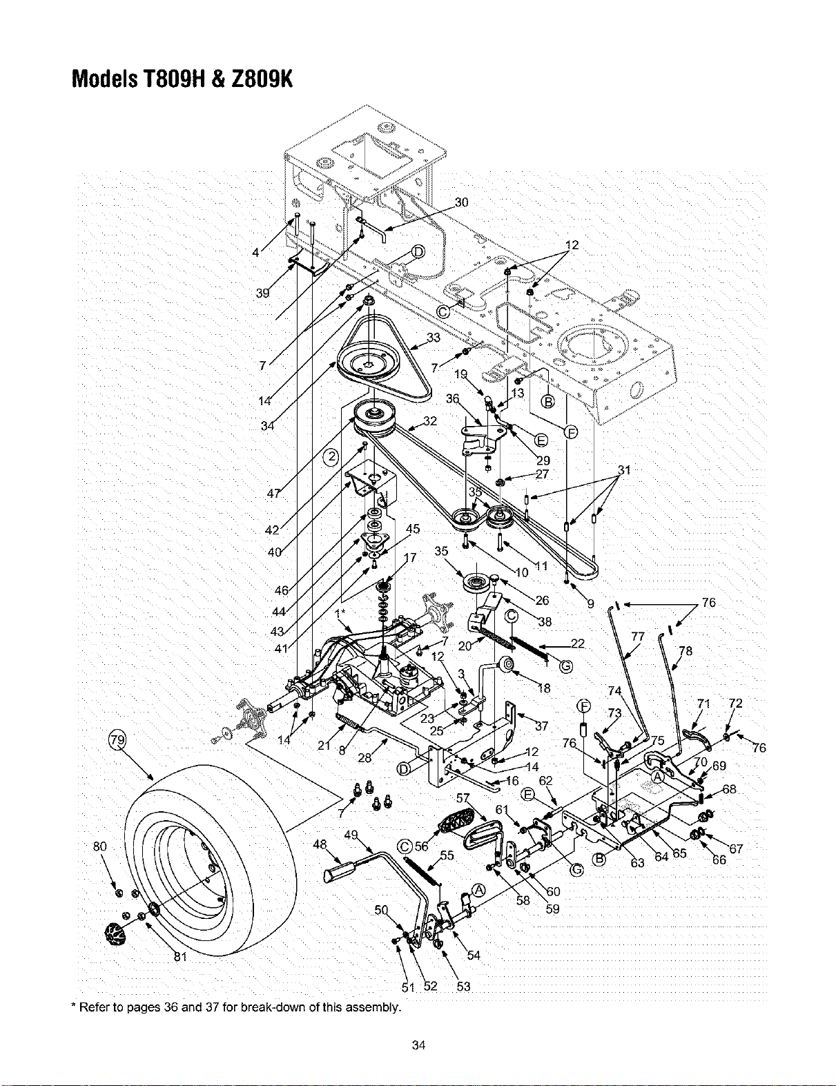
ModelsT809H&Z809K
46/
44 /
43./
41/
35
12
78
57.
59
74
71 72
* Refer to pages 36 and 37 for break-down of this assembly.
53
34

ModelsT809H&Z809K
RER PART
NO. NO.
1. 618-0376A
2. 618-04148
3. 647-04023
4. 710-0176
5. 710-0347
6. 710-0642
7. 710-0726
8. 710-0805
9. 710-0809
10. 710-1007
11. 710-3011
12. 712-0130
13. 712-0241
14. 712-0702
15. 712-3004A
16. 714-0111
17. 718-0771A
18. 720-04028
19. 723-3018
20. 732-0478
21. 732-0716
22. 732-0963
23. 736-0105
24. 736-0169
25. 736-0642
26. 738-0322
27. 738-0372B
28. 747-04136
29. 747-1127
30. 747-1185
31. 750-0566A
32. 754-0467
33. 754-0468
34. 756-0665
35. 756-0981A
36. 783-04442
37. 783-0667B
38. 783-0669
39. 783-0693
40. 618-04152
41. 710-0627
42. 710-3015
DESCRIPTION
Transmission Assembly: Two Speed
Variable Speed Pulley Assembly
Shift Rod Assembly
Hex Bolt 5/16-18 x 2.75
Hex Bolt 3/8-16 x 1.75
TT Screw 1/4-20 x 0,75
AB Screw 5/16-12 x 0,75
Hex Bolt 5/16-18 x 1.5
TT Screw 1/4-20 x 1,25
TT Sems Screw 3/8-16 x 1,5
Hex Bolt 3/8-16 x 2.25
Lock Nut 3/8-16
Hex Nut 3/8-24
Flanged Nut
Flanged Lock Nut
Cotter Pin
Pulley Hub
Shift Knob
Ball Joint
Extension Spring
Extension Spring
Extension Spring
Bell Washer
Lock Washer 3/8
Flat Washer
Shoulder Screw
Shoulder Spacer
Brake Red
Rod: Idler Adjustment
Rod: Belt Guard
Spacer
Belt: V Type
Belt: V Type
Pulley
Idler Pulley: Flat
Idler Bracket: Center Double
Torque Bracket
Idler Bracket
Axle Bracket
Bracket: Variable Speed
Lock Bolt 5/16-24 x 0,75
Hex Bolt 1/4-20 x 0.75
REF.
NO.
43,
44,
45,
46,
47,
48,
49,
50,
51,
52,
53,
54,
55,
56,
57,
58,
59,
61,
62,
64,
65,
66,
67,
68,
69,
70,
71,
72,
73,
74,
75,
76,
77,
78,
79,
80,
81,
PART
NO.
712-3027
718-04012
736-0362
741-0600
656-0059A
735-3049
783-0773A
736-3008
710-1611B
710-0650
741-3065B
647-0031C
732-0963
735-0662
683-0266
710-1260A
647-0032A
712-0130
711-04159
738-0155
783-0653F
741-0225
726-04028
732-0335
712-3004A
783-0732
783-0780B
736-0262
748-04039
738-0380
732-0955
714-0104
747-04093
747-04096
634-0104
634-0070
734-0255
734-1730
734-2290A
736-0430
712-3050
712-3026
DESCRIPTION
Flanged Lock Nut
Cup: Bearing
Flat Washer
Ball Bearing
Variable Speed Pulley
Brake Pad
Brake Pedal
Flat Washer
TT Screw 5/16-18 x 0,75
TT Screw 5/16-18 x 0,875
Hex Flange Bearing: Split
Brake Control Assembly
Extension Spring
Control Pad
Drive Pedal Assembly
LD Screw 5/16-18 x 0.75
Speed Control Assembly
Hex Lock Nut 3/8-16
Pin
Shoulder Screw
Steering Support Bracket
Hex Flange Bearing
Push Nut
Compression Spring
Flange Lock Nut
Lock-Out Bracket
Neutral Return Bracket
Flat Washer
Cruise Latch
Shoulder Screw
Extension Spring
Cotter Pin
Brake Lock Red
Cruise Control Rod
Wheel Assembly
Rim Assembly
Air Valve
Tire
Hub Cap
Flat Washer
Lug Nut 7/16-14
Jam Nut
IMPORTANT: Fora proper
working machine, use
Factory Approved Parts.
V-belts are designed to
engage and disengage
safely. A substitute (non
OEM) V-belt can be
dangerous by not
disengaging completely.
35
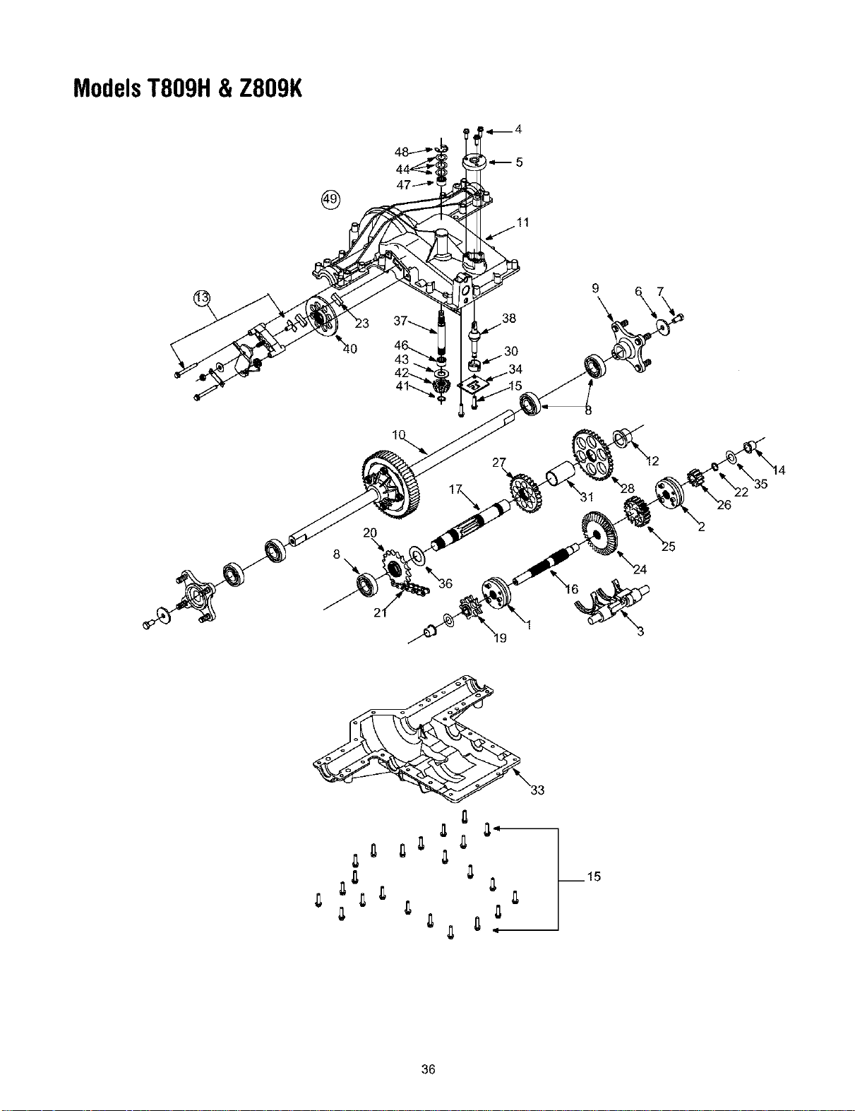
ModelsT809H& Z809K
38
.30
9
8
2O
1}
36

ModelsT809H&Z809K
REE PART
NO. NO.
1 618-0225
2 618-0226
3 618-0227A
4 710-0642
5 718-04053
6 736-0227
7 710-3119
8 741-0681
9 618-0365
10 618-0368
11 719-0379A
12 741-0476
13 661-0012
14 741-04085
15 710-0788
16 711-1051A
17 711-1216
19 713-0446
20 713-0447
21 713-0448
22 716-0131
23 717-0678
24 717-1438
25 717-1439
26 717-1440
27 717-1441
28 717-1442
30 718-0504
31 718-0505
33 719-0385
34 718-0540
35 736-0337
36 736-3046A
37 711-1235
38 747-1140
40 761-0215
41 716-0114
42 717-1463
43 736-0335
44 736-0336
736-0337
736-0349
46 741-0335
47 741-0696
48 716-0231
49 618-0376A
DESCRIPTION
Reverse Collar Assembly
Hi-Lo Collar Assembly
Shift Fork Assembly
Self-tapping Screw, 1/4-20 x .75
Shft. Cover
Flat Washer
Lock bolt 3/8-16 x 0.75
Ball Bearing
Wheel Hub Assembly
Differential Axle Assembly
Upper Housing
Flanged Bearing
Brake Assembly
Flanged Bearing
TT Screw 1/4-20 x 1.0
Drive Shaft
Output Shaft
9-tooth Sprocket
16-tooth Sprocket
22-1ink Chain, .625
External Snap Ring
Brake Pad
41-tooth Bevel Gear
20-tooth Spur Gear
lO-tooth Spur Gear
27-tooth Spur Gear
37-tooth Spur Gear
Shifter Insert
Shifter Cover
Lower Housing
Lockout Plate
Flat Washer, 5/8 x 1.0
Flat Washer, 1.01 x 1.86 x .060
Input Shaft
Shift Lever
Disc Brake
Retaining Ring, .56
13-tooth Bevel Gear
Flat Washer
Flat Washer, 5/8 x 1.0 x .030*
Flat Washer, 5/8 x 1.0 x ..040*
Falt Washer,5/8 x 1.0 x .020*
Needle Bearing
Needle Bearing
E-ring, .75
Transmisssion Assembly Complete
NOTE: Transmission has a grease capacity of 32 oz. Orderpart number 737-0148.
NOTE: Upon reassembling transmission input shaft for any reason, refill its cavity with approximately 2/3 oz. of grease.
Order part number 737-0289.
37
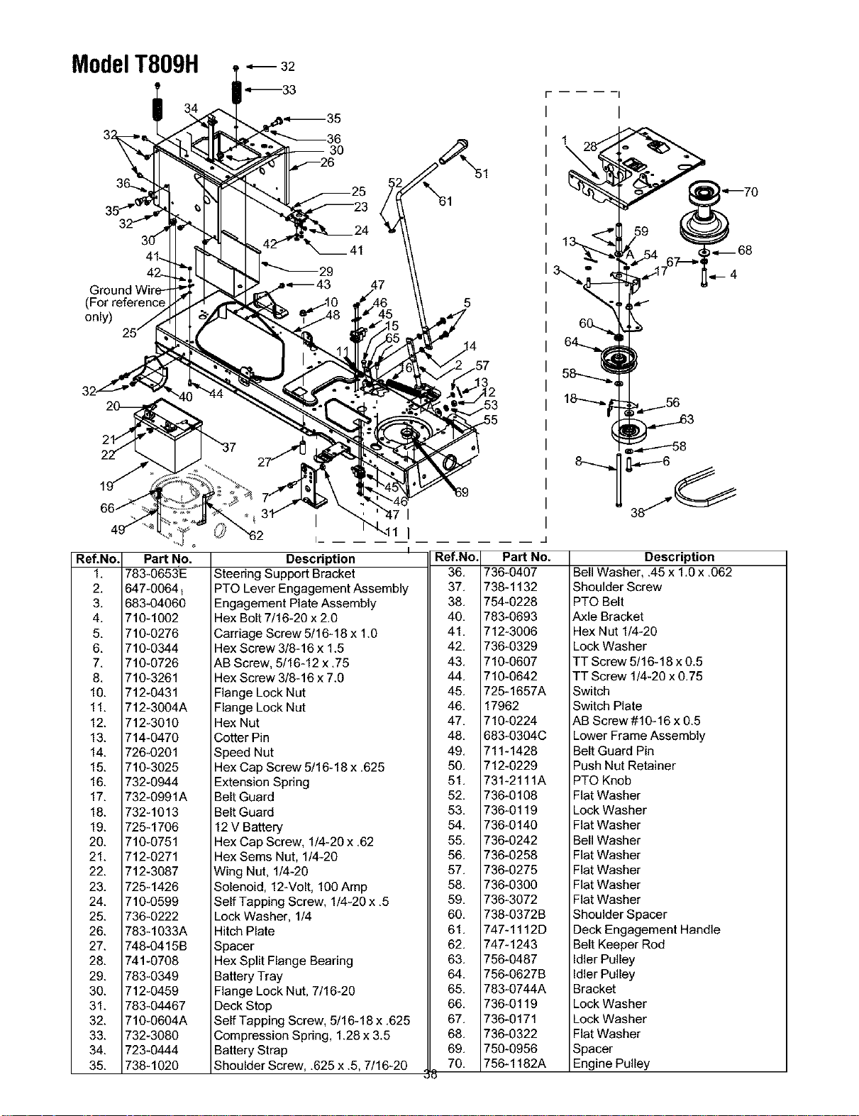
ModelT809H .,,--32
',--33
(
only)
Ref.No. Part No.
1. 783-0653_
2. 647-0064_
3. 683-04060
4. 710-1002
5. 710-0276
6. 710-0344
7. 710-0726
8. 710-3261
10. 712-0431
11. 712-3004A
12. 712-3010
13. 714-0470
14. 726-0201
15. 710-3025
16. 732-0944
17. 732-0991A
18. 732-1013
19. 725-1706
20. 710-0751
21. 712-0271
22. 712-3087
23. 725-1426
24. 710-0599
25. 736-0222
26. 783-1033A
27. 748-0415B
28. 741-0708
29. 783-0349
30. 712-0459
31. 783-04467
32. 710-0604A
33. 732-3080
34. 723-0444
35. 738-1020
I I
I_ I
I
Description
Steering Support Bracket
PTO Lever Engagement Assembly
Engagement Plate Assembly
Hex Bolt 7/16-20 x 2.0
Carriage Screw 5/16-18 x 1.0
Hex Screw 3/8-16 x 1.5
AB Screw, 5/16-12 x .75
Hex Screw 3/8-16 x 7.0
Flange Lock Nut
Flange Lock Nut
Hex Nut
Cotter Pin
Speed Nut
Hex Cap Screw 5/16-18 x .625
Extension Spring
Belt Guard
Belt Guard
12 V Battery
Hex Cap Screw, 1/4-20 x .62
Hex Sems Nut, 1/4-20
Wing Nut, 1/4-20
Solenoid, 12-Volt, 100 Amp
Self Tapping Screw, 1/4-20 x .5
Lock Washer, 1/4
Hitch Plate
Spacer
Hex Split Flange Bearing
Battery Tray
Flange Lock Nut, 7/16-20
Deck Stop
Self Tapping Screw, 5/16-18 x .625
Compression Spring, 1.28 x 3.5
Battery Strap
Shoulder Screw, .625 x .5, 7/16-20
\
Re&No.I PaN No.
36. 1736-0407
37 1738-1132
38. 1754-0228
40. 1783-0693
41 1712-3006
42. 1736-0329
43. 1710-0607
44 1710-0642
45. 1725-1657A
46. 117962
47 1710-0224
48. 1683-0304C
49. 1711-1428
50. 1712-0229
51 1731-2111A
52. 1736-0108
53. 1736-0119
54. 1736-0140
55. 1736-0242
56. 1736-0258
57 1736-0275
58. 1736-0300
59. 1736-3072
60. 1738-0372B
61 1747-1112D
62. 1747-1243
63. 1756-0487
64. 1756-0627B
65. 1783-0744A
66. 1736-0119
67 1736-0171
68. 1736-0322
69. 1750-0956
70 1756-1182A
Description
Bell Washer, .45 x 1.Ox .062
Shoulder Screw
PTO Belt
Axle Bracket
Hex Nut 1/4-20
Lock Washer
TT Screw 5/16-18 x 0.5
TT Screw 1/4-20 x 0.75
Switch
Switch Plate
AB Screw #10-16 x 0.5
Lower Frame Assembly
Belt Guard Pin
Push Nut Retainer
PTO Knob
Flat Washer
Lock Washer
Flat Washer
Bell Washer
Flat Washer
Flat Washer
Flat Washer
Flat Washer
Shoulder Spacer
Deck Engagement Handle
Belt Keeper Rod
Idler Pulley
Idler Pulley
Bracket
Lock Washer
Lock Washer
Flat Washer
Spacer
Engine Pulley
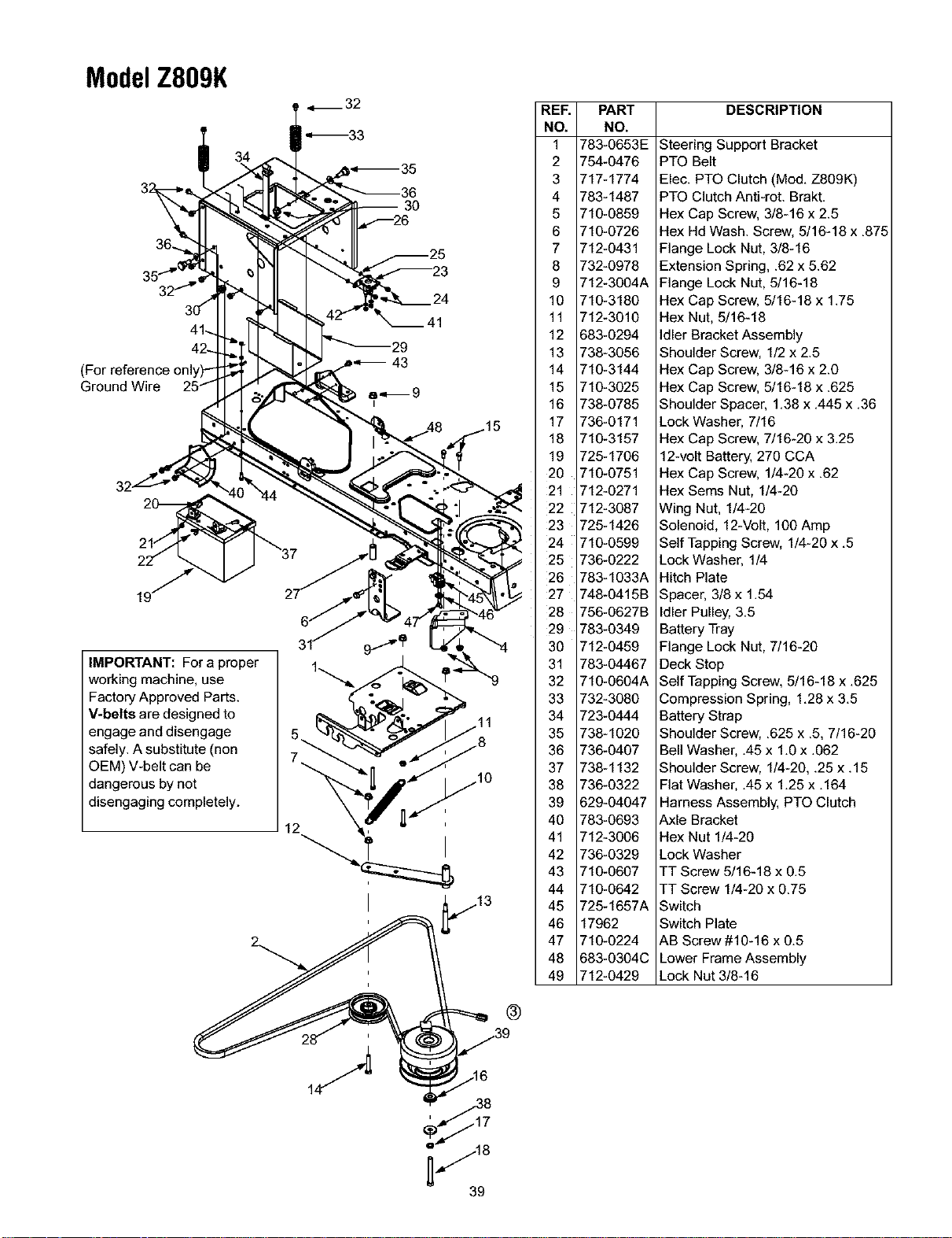
ModelZ809K
(
Ground Wire
IMPORTANT: For a proper
working machine, use
Factory Approved Parts.
V-belts are designed to
engage and disengage
safely. A substitute (non
OEM) V-belt can be
dangerous by not
disengaging completely.
12
_41
29
I
REF.
NO.
1
2
3
4
5
6
7
8
9
10
11
12
13
14
15
16
17
18
19
2O
21
22
23
24
25
26
27
28
29
3O
31
32
33
34
35
36
37
38
39
4O
41
42
43
44
45
46
47
48
49
PART
NO.
783-0653E
754-0476
717-1774
783-1487
710-0859
710-0726
712-0431
732-0978
712-3004A
710-3180
712-3010
683-0294
738-3056
710-3144
710-3025
738-0785
736-0171
710-3157
725-1706
710-0751
712-0271
712-3087
725-1426
710-0599
736-0222
783-1033A
748-0415B
756-0627B
783-0349
712-0459
783-04467
710-0604A
732-3080
723-0444
738-1020
736-0407
738-1132
736-0322
629-04047
783-0693
712-3006
736-0329
710-0607
710-0642
725-1657A
17962
710-0224
683-0304C
712-0429
DESCRIPTION
Steering Support Bracket
PTO Belt
Elec. PTO Clutch (Mod. Z809K)
PTO Clutch Anti-rot. Brakt.
Hex Cap Screw, 3/8-16 x 2.5
Hex Hd Wash. Screw, 5/16-18 x .875
Flange Lock Nut, 3/8-16
Extension Spring, .62 x 5.62
Flange Lock Nut, 5/16-18
Hex Cap Screw. 5/16-18 x 1.75
Hex Nut, 5/16-18
Idler Bracket Assembly
Shoulder Screw, 1/2 x 2.5
Hex Cap Screw. 3/8-16 x 2.0
Hex Cap Screw, 5/16-18 x .625
Shoulder Spacer, 1.38 x .445 x .36
Lock Washer. 7/16
Hex Cap Screw, 7/16-20 x 3.25
12-volt Battery. 270 CCA
Hex Cap Screw. 1/4-20 x .62
Hex Sems Nut, 1/4-20
Wing Nut, 1/4-20
Solenoid, 12-Volt, 100 Amp
Self Tapping Screw, 1/4-20 x .5
Lock Washer. 1/4
Hitch Plate
Spacer. 3/8 x 1.54
Idler Pulley, 3.5
Battery Tray
Flange Lock Nut, 7/16-20
Deck Stop
Self Tapping Screw, 5/16-18 x .625
Compression Spring, 1.28 x 3.5
Battery Strap
Shoulder Screw, .625 x .5, 7/16-20
Bell Washer, .45 x 1.0 x .062
Shoulder Screw, 1/4-20, .25 x. 15
Flat Washer, .45 x 1.25 x .164
Harness Assembly. PTO Clutch
Axle Bracket
Hex Nut 1/4-20
Lock Washer
TT Screw 5/16-18 x 0.5
TT Screw 1/4-20 x 0.75
Switch
Switch Plate
AB Screw #10-16 x 0.5
Lower Frame Assembly
Lock Nut 3/8-16
®
i....--18
39
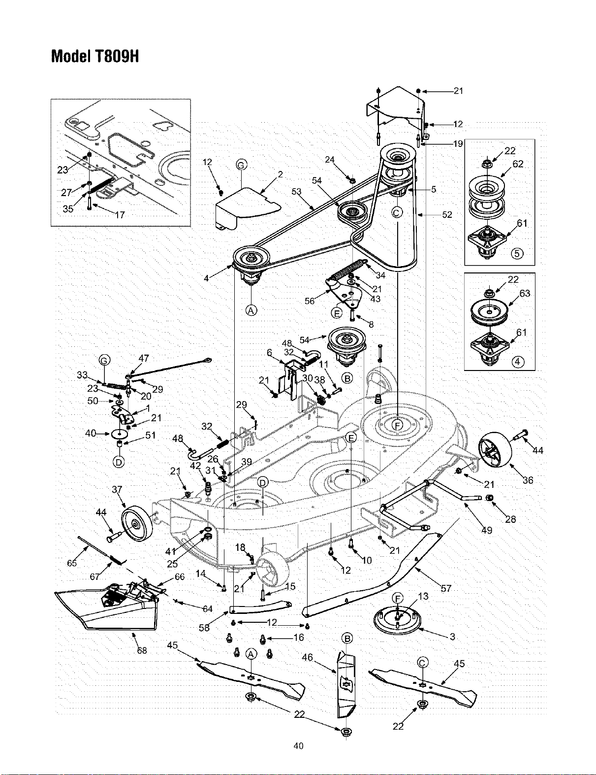
ModelT809H
7oS°-.,7-:LL
12
21
24
54
\
-5 I*/2_ */62
4O

ModelT809H
Re_ Part No.
No.
1, 17116
2, 17258D
3, 17982
4, 618-0430A
5, 618-0595
6, 683-0254
7. 683-04121
8, 710-0344
9, 710-0501
10. 710-0514
11. 710-0528
12. 710-0599
13. 710-0650
14. 710-0751
15. 710-0805
16. 710-1260A
17. 710-3180
18. 711-04069
19. 711-0993
20. 711-1554
21. 712-0324
22. 712-0417A
23. 712-0429
24. 712-0431
25. 712-0641
26. 712-3006
27. 712-3010
28. 712-3083
29. 714-0470
30. 717-04074
31. 726-0233
32. 732-0306A
33. 732-0429A
34. 732-0594A
35. 732-1165
36. 734-04039
Description Ref. Part No.
No.
Deck Brake Assembly 37. 734-0973
Belt Cover 38. 736-0119
Spindle Plate 39. 736-0270
Spindle Assembly: Pulley w/fig, 40. 736-0418A
Spindle Assembly: Double Pulley 41. 736-0760
Bracket Assembly: Deck Hanger LH 42. 737-04003B
Deck Assembly 46" SD w/Nozzle 43. 738-0347
Hex Bolt 3/8-16 x 1.5 44. 738-0373
Hex Bolt 1/4-20 x 2.0 45. 742-0611A
Hex Bolt 3/8-16x 1.0 46. 742-0612A
Hex Bolt 5/16-18 x 1,25 47. 746-1107
]-T Screw 1/4-20 x 0,5 48. 747-1116
]-T Screw 5/16-18 x 0.875 49. 747-1130B
Hex Bolt 1/4-20 x 0.620 50. 748-0234
Hex Bolt 5/16-18x 1,5 51. 750-1291
LD Screw 5/16-18 x 0,75 52. 754-0228
Description
Deck Wheel 5.0 x 1.38
Lock Washer
Bell Washer
Flat Washer
Lock Washer
Water Nozzle
Shoulder Spacer
Shoulder Screw 3/8-16
Blade: 16.28" Three in One
Blade: 14.88" Three in One
Cable: Bracket
Rod: Deck Release Handle
Rod: Front Adjustment
Shoulder Spacer
Spacer
Belt: V Type
Hex Bolt 5/16-18 x 1,75 53. 754-0349
Grass Catcher Pin 54. 756-0627B
Belt Guard Pin 55. 771-11725A
Pin 1/4-20 56. 783-0139A
Hex Lock Nut 1/4-20 57. 783-0141
Flange Nut 58. 783-0142
Lock Nut 5/16-18 59. 783-1025
Flanged Lock Nut 3/8-16 60. 783-1347B
Belt: V Type
LdlerPulley
Label: Danger Tag
LdlerBracket
Deck Skirt: Center
Deck Skirt RH
Chute Stop
Belt Cover
Hex Nut M16 61. 619-0042
Hex Nut 1/4-20 17983
Hex Nut 5/16-18 738-1128
Lock Nut 1/2-13 741-0919
Cotter Pin 62. 756-1214
Gear: Deck Adjustment 63. 756-1187
Push Nut 64. 726-0106
Compression Spring 65. 711-0792
Extension Spring 66. 703-1693A
Extension Spring 67. 732-0602
Extension Spring 68. 731-1032B
Deck Wheel 5.0 dia. Ball
Spindle Housing
Bearing
Spindle Shaft
Ball Bearing
Deck Pulley: Double
Deck Pulley
Speed Nut
Hinge Pin
Mounting Bracket
Torsion Spring
Chute Deflector: Side Discharge
IMPORTANT: For a proper
working machine, use
Factory Approved Parts.
V-belts are designed to
engage and disengage
safely. A substitute (non
OEM) V-belt can be
dangerous by not
disengaging completely.
41
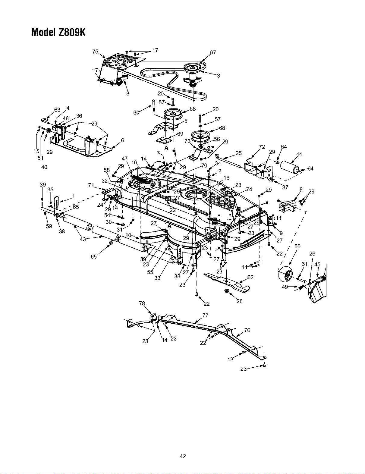
ModelZ809K
5
40
47 14
72
44
39
l
77
76
26
42

ModelZ809K
RER PART
NO. NO.
1. 12650
2. 16606
3. 618-0671
4. 683-0254
5. 683-0459
6. 683-0608
7. 683-0609
8. 683-0610
9. 683-0617
10. 703-2093
13. 710-0216
14. 710-0514
15. 710-0528
16. 710-1260A
17. 710-0726
20. 710-3011
21. 710-3073
22. 710-3168
23. 710-3178
24. 711-0332
25. 711-1737
26. 711-1762
27. 712-0229
28. 712-0417A
29. 712-0130
30. 712-0641
31. 712-0429
32. 712-3010
33. 712-3022
35. 714-0145
36. 714-0470
37. 714-3004
38. 715-0108
39. 714-0162
40. 717-1553B
41. 721-04041
DESCRIPTION
Bracket, Adjustment, Height
Bracket, Hook, Retainer
Spindle Assembly, Pulley, 5.39 Dia x .5625
Bracket Assembly, Deck, Hanger LH
Idlr Assembly, 54"
Bracket Assembly, Lift, 54"
Bracket Assembly, LH-Front
Bracket Assembly, RH-Front
Stop Assembly, Chute
Baffle, RR, Inner
Hex Screw 3/8-16 x 0.75
Hex Screw 3/8-16 x 1.0
Hex Screw, 5/16-18 x 1.25
LD Screw 5/16-18 x 0.75
AB Screw 5/16-12 x 0.75
Hex Screw, 3/8-16 x 2.25
Hex Screw, 5/16-18 x 2.25
Bolt, Carriage, 3/8-16 x 1.0
Short Neck Carriage Bolt 3/8-16 x .75
REE PART
NO. NO.
43. 731-0335
44. 731-3005
45. 731-3131A
46. 732-0306
47. 732-0459
48. 732-0934
49. 732-3070
50. 734-04039
51. 736-0119
54. 736-0760
55. 736-0921
56. 736-3039
57. 736-3072
58. 737-04003B
59. 738-0295
60. 738-1229A
61. 738-0373
62. 742-0677
63. 747-1116
DESCRIPTION
Roller, Deck
Front Roller
Deflector, Chute
Spring, Compression, .406 x .531 x 1.75
Spring, Extension, .94 Dia x 6.74
Spring, Extension, 1.15 Dia x 5.99
Torsion Spring .44 I.d. x 2.10
Deck Wheel, 5" Dia.
Lock Washer
Lock Washer
Lock Washer
Flat Washer .406 ID X 1.5 x 1lga
Washer, Flat .38 ID x.93 OD x.110
Water Nozzle: Deck Wash-Out System
Shoulder Screw, .750 x .47.12
Shoulder Screw
Shoulder Screw
Blade, 18.50"
Deck Release Handle Rod, .375 Dia
Pin, Clevis, .50 Dia x .78
Pin, Roller, .5" Dia x 10.06.
Pin, Hinge, Dia .375 x 14.06
Push Nut Retainer
Nut, Hex Flange, 5/8-18
Nut, Lock, 3/8-16
Hex Nut M16
Nut, Flange Lock, 5/16-18
Nut, Hex, 5/16-18, Gr5
Nut, Hex Lock, 1/2-13
Pin, Click, .092 x 1.64
Pin, Cotter, 1/8x 1.25
Pin, Cotter, 3/32 x 1.25
Pin, Spring 1/4 Dia x 1.00
Cotter Pin
Adjustment, Deck, Gear
Water Nozzle Adaptor
64. 750-0151
65. 750-0212
67. 754-0642
68. 756-3105
69. 783-04013A
70. 683-04127
783-04232
71. 783-1453
72. 783-1454
73. 783-1455
74. 783-1470
75. 783-1471
76. 783-1482
77. 783-1483
78. 783-1484
79. 703-3279
Spacer .550 ID x .755 OD x 1.1
Spacer, .82 ID x 1.00 OD x .53
Belt, V-Type, B Section
Pulley, Idler, 5.0 Dia.
Bracket, Stabilizing
Deck Assembly SD: 54" w/Water Nozzle
Deck: SD w/Water Nozzle Ftg.
Bracket, Mounting, 54" Roller
Bracket, Roller, Front
Bracket, Idler
Cover, Spindle RH
Cover, Spindle LH
RH Skirt
LH Skirt
LH Extension Skirt
Chute Stop (not shown)
IMPORTANT: Fora proper
working machine, use
Factory Approved Parts.
V-belts are designed to
engage and disengage
safely. A substitute (non
OEM) V-belt can be
dangerous by not
disengaging completely.
NOTE: For painted parts, please refer to
the list of color codes below. Please add the
applicable color code, wherever needed, to
the part number to order a replacement part.
For instance, if a part numbered 700-xxxx is
painted Powder Black, the part number to
order would be 700-xxxx-0637.
Red: 0638
Oyster Gray: 0662
Powder Black: 0637
43

MANUFACTURER'S LIMITED WARRANTY FOR:
O ®
The limited warranty set forth below is given by Troy-Bilt LLC
with respect to new merchandise purchased and used in the
United States, its possessions and territories.
"Troy-Bilt" warrants this product against defects in material
and workmanship for a period of two (2) years commencing
on the date of original purchase and will, at its option, repair or
replace, free of charge, any part found to be defective in
materials or workmanship. This limited warranty shall only
apply if this product has been operated and maintained in
accordance with the Operator's Manual furnished with the
product, and has net been subject to misuse, abuse,
commercial use. neglect, accident, improper maintenance,
alteration, vandalism, theft, fire. water, or damage because of
other peril or natural disaster. Damage resulting from the
installation or use of any part, accessory or attachment not
approved by Troy-Bilt for use with the product(s) covered by
this manual will void your warranty as to any resulting
damage.
Normal wear parts are warranted to be free from defects in
material and workmanship for a period of thirty (30) days from
the date of purchase. Normal wear parts include, but are not
limited to items such as: batteries, belts, blades, blade
adapters, grass bags, rider deck wheels, seats, snow thrower
skid shoes, shave plates, auger spiral rubber and tires.
HOW TO OBTAIN SERVICE: Warranty service is available,
WITH PROOF OF PURCHASE, through your local authorized
service dealer. To locate the dealer in your area, check your
Yellow Pages, or contact Troy-Bilt LLC at P.O. Box 361131,
Cleveland, Ohio 44136-0019. or call 1-866-840-6483 or 1-
330-558-7220. or log on to our Web site at www.troybilt.com.
This limited warranty does not provide coverage in the
following cases:
a. The engine or component parts thereof. These items
may carry a separate manufacturer's warranty. Refer
to applicable manufacturer's warranty for terms and
conditions.
b. Log splitter pumps, valves, and cylinders have a
separate one year warranty.
c. Routine maintenance items such as lubricants, filters,
blade sharpening, tune-ups, brake adjustments, clutch
adjustments, deck adjustments, and normal
deterioration of the exterior finish due to use or
exposure.
d. Service completed by someone other than an
authorized service dealer.
e. Troy-Bilt does not extend any warranty for products
sold or exported outside of the United States, its
possessions and territories, except those sold through
Troy-Bilt's authorized channels of export distribution.
f. Replacement parts that are not genuine Troy-Bilt parts.
g. Transportation charges and service calls.
No implied warranty, including any implied warranty of
merchantability of fitness for a particular purpose,
applies after the applicable period of express written
warranty above as to the parts as identified. No other
express warranty, whether written or oral, except as
mentioned above, given by any person or entity,
including a dealer or retailer, with respect to any product,
shall bind Troy-Bilt. During the period of the warranty, the
exclusive remedy is repair or replacement of the product
as set forth above.
The provisions as set forth in this warranty provide the
sole and exclusive remedy arising from the sale. Troy-Bitt
shall not be liable for incidental or consequential loss or
damage including, without limitation, expenses incurred
for substitute or replacement lawn care services or for
rental expenses to temporarily replace a warranted
product.
Some states do not allow the exclusion or limitation of
incidental or consequential damages, or limitations on how
long an implied warranty lasts, so the above exclusions or
limitations may not apply to you.
In no event shall recovery of any kind be greater than the
amount of the purchase price of the product sold. Alteration
of safety features of the product shall void this warranty.
You assume the risk and liability for loss. damage, or injury to
you and your property and/or to others and their property
arising out of the misuse or inability to use the product.
This limited warranty shall not extend to anyone other than
the original purchaser or to the person for whom it was
purchased as agift.
HOW STATE LAW RELATES TO THIS WARRANTY: This
limited warranty gives you specific legal rights, and you may
also have other rights which vary from state to state.
IMPORTANT: Owner must present Original Proof of
Purchase to obtain warranty coverage.
Troy-Bilt LLC,P.O.BOX361131CLEVELAND,OHIO44136-0019; Phone:1-866-840-6483,1-330-558-7220