Loading ...
Loading ...
Loading ...
Withthetractorparkedonafirm,levelsurface,
placethedeckliftleverinthetopnotch(highest
position)androtatethebladenearestthedischarge
chutesothatitisparallelwiththetractor.
Measurethedistancefromfrontofthebladetipto
thegroundandrearofthebladetiptotheground.
Thefirstmeasurementtakenshouldbebetween
1/4"and3/8"lessthanthesecondmeasurement.
Determinetheapproximatedistancenecessaryfor
properadjustmentandproceedtothenextstep.
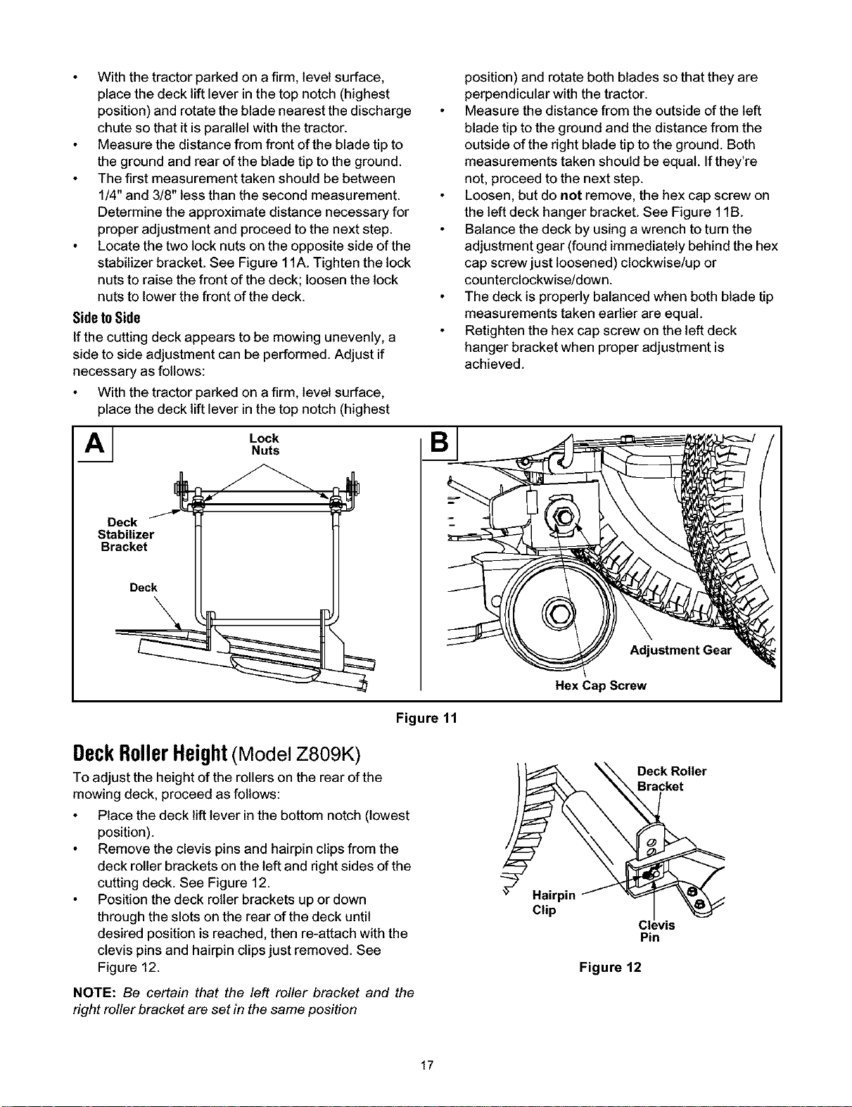
Locatethetwolocknutsontheoppositesideofthe
stabilizerbracket.SeeFigure11A.Tightenthelock
nutstoraisethefrontofthedeck;loosenthelock
nutstolowerthefrontofthedeck.
SidetoSide
If the cutting deck appears to be mowing unevenly, a
side to side adjustment can be performed. Adjust if
necessary as follows:
With the tractor parked on a firm, level surface,
place the deck lift lever in the top notch (highest
AI LockNuts
Deck
Stabilizer
Bracket
Deck
position) and rotate both blades so that they are
perpendicular with the tractor.
Measure the distance from the outside of the left
blade tip to the ground and the distance from the
outside of the right blade tip to the ground. Both
measurements taken should be equal. If they're
not, proceed to the next step.
Loosen, but do not remove, the hex cap screw on
the left deck hanger bracket. See Figure 1lB.
Balance the deck by using a wrench to turn the
adjustment gear (found immediately behind the hex
cap screw just loosened) clockwise/up or
counterclockwise!down.
The deck is properly balanced when both blade tip
measurements taken earlier are equal.
Retighten the hex cap screw on the left deck
hanger bracket when proper adjustment is
achieved.
Adjustment Gear
Hex Cap Screw
Figure 11
DeckRollerHeight(Model Z809K)
To adjust the height of the rollers on the rear of the
mowing deck, proceed as follows:
Place the deck lift lever inthe bottom notch (lowest
position).
Remove the clevis pinsand hairpin clipsfrom the
deck roller brackets on the left and rightsides of the
cutting deck. See Figure 12.
Position the deck roller brackets up or down
through the slots on the rear of the deck until
desired position is reached, then re-attach with the
clevis pins and hairpin clipsjust removed. See
Figure 12.
_ Deck Roller
\ racket
(H;pp'nf _
Cl_,vis
Pin
Figure 12
NOTE: Be certain that the left roller bracket and the
right roller bracket are set in the same position
17
Loading ...
Loading ...
Loading ...