Loading ...
Loading ...
Loading ...
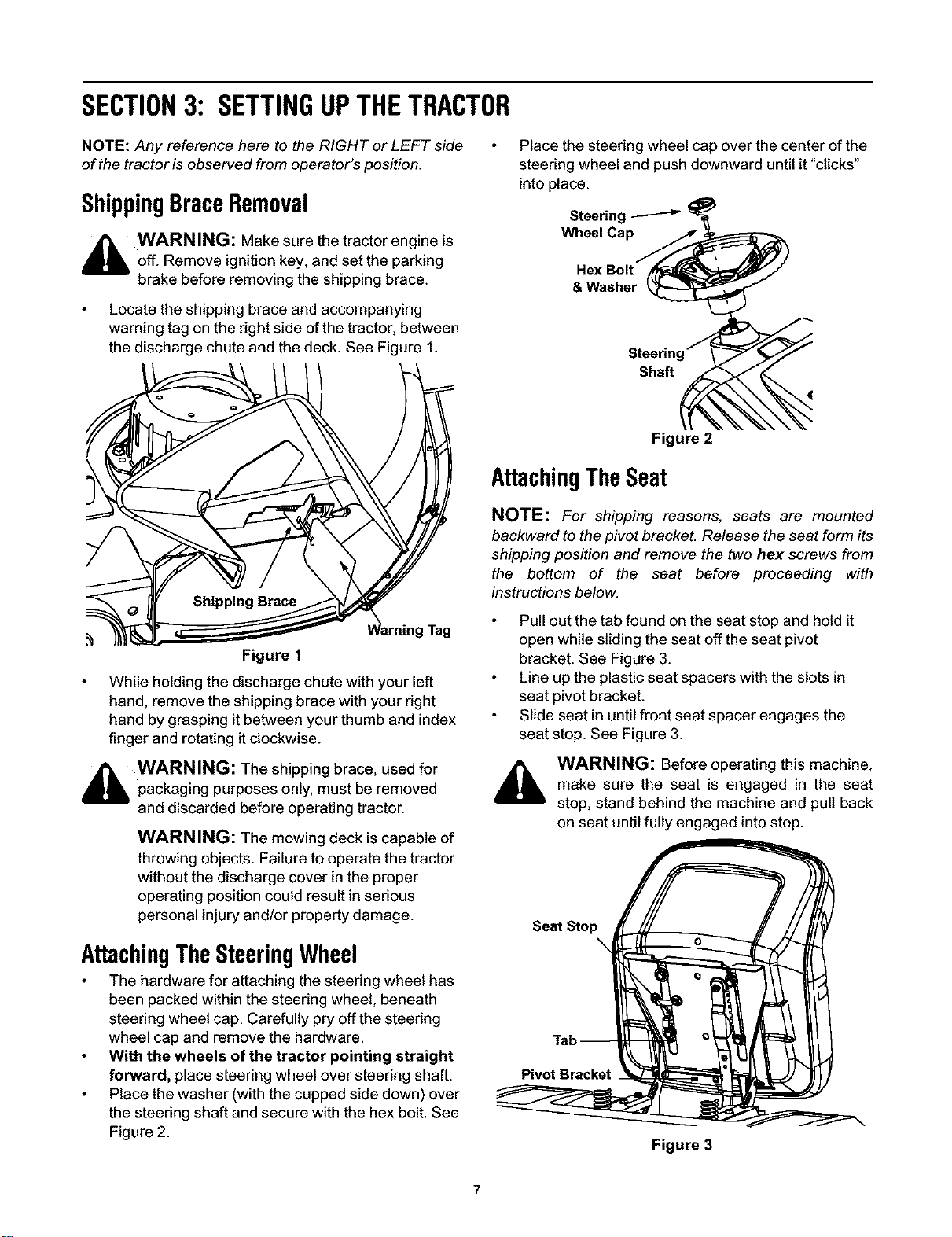
SECTION3: SETTINGUPTHETRACTOR
NOTE: Any reference here to the RIGHT or LEFT side
of the tractor is observed from operator's position.
ShippingBraceRemoval
_ WARNING: Make sure the tractor engine is
off. Remove ignition key, and set the parking
brake before removing the shipping brace.
Locate the shipping brace and accompanying
warning tag on the right side of the tractor, between
the discharge chute and the deck. See Figure 1.
Figure 1
While holding the discharge chute with your left
hand, remove the shipping brace with your right
hand by grasping it between your thumb and index
finger and rotating it clockwise.
_i WARNING: The shipping brace, used for
packaging purposes only, must be removed
and discarded before operating tractor.
WARNING: The mowing deck is capable of
throwing objects. Failure to operate the tractor
without the discharge cover in the proper
operating position could result in serious
personal injury and/or property damage.
AttachingTheSteeringWheel
The hardware for attaching the steering wheel has
been packed within the steering wheel, beneath
steering wheel cap. Carefully pry offthe steering
wheel cap and remove the hardware.
With the wheels of the tractor pointing straight
forward, place steering wheel over steering shaft.
Place the washer (with the cupped side down) over
the steering shaft and secure with the hex bolt. See
Figure 2.
Place the steering wheel cap over the center of the
steering wheel and push downward until it "clicks"
into place.
Steering _ _
Wheel Capri,
Hex Bolt
& Washer _
Steering'_
Shaft _
Figure 2
AttachingTheSeat
NOTE: For shipping masons, seats are mounted
backward to the pivot bracket. Release the seat form its
shipping position and remove the two hex screws from
the bottom of the seat before proceeding with
instructions below.
Pull out the tab found on the seat stop and hold it
open while sliding the seat off the seat pivot
bracket. See Figure 3.
Line up the plastic seat spacers with the slots in
seat pivot bracket.
Slide seat in until front seat spacer engages the
seat stop. See Figure 3.
WARNING: Before operating this machine,
make sure the seat is engaged in the seat
stop, stand behind the machine and pull back
on seat until fully engaged into stop.
Seat Stop
X
Pivot Bracket
Figure 3
Loading ...
Loading ...
Loading ...