Loading ...
Loading ...
Loading ...
IMPORTANT: Note the routing of the lower drive belt
around both the pulleys and the belt keepers before
performing the following steps.
Locate the variable-speed pulley through the
battery tray opening. See Figure 18.
Remove the variable-speed pulley by loosening the
hex bolt that secures itto the transmission. Use a
second wrench to hold the hex nut on the bottom
side of the pulley.
Slide the belt off the variable-speed pulley as you
lift the pulley up and out through the battery tray
opening.
Remove rear idler pulley from the double- idler
bracket while loosening the belt from around both
the rear and the front idler pulleys. See Figure 18.
Remove the hex bolt from the center of the engine
pulley (Model T809H) or the electric PTO clutch
(Model Z809K) and gently lower it off the engine
crankshaft. Be careful not to lose any washers or
which may be found on top of the PTO clutch.
IMPORTANT: When remounting the PTO clutch, torque
the center hex bolt to between 38 foot-pounds and 50
foot-pounds.
Remove the drive belt by feeding itfrom both ends
toward the front idler pulley on the double-idler
bracket. See Figure 20.
Reassemble by following the above steps in
reverse order.
Reroute the new belt around the pulleys, belt
keepers and keeper pins exactly as the old one was
routed. Refer to Figure 18.
The drive pedal is properly adjusted when the hole
found in the double-idler bracket has approximately
1-3/8" of travel with ten pounds of pressure applied to
the drive pedal. See Figure 19.
Double-idler Bracket
.o,e\ Adju"' rRod
Front of Tractor
NOTE: Viewshownfromabovetractor.
Figure 19
Adjust the drive pedal after replacing the drive belts on
your tractor, ifnecessary, as follows:
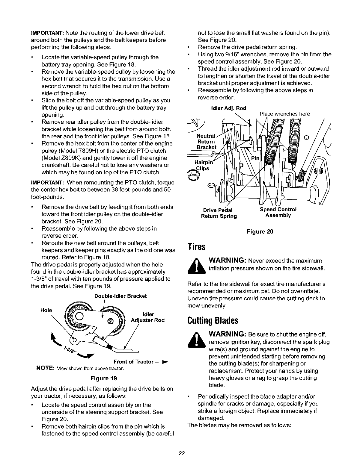
Locate the speed control assembly on the
underside of the steering support bracket. See
Figure 20.
Remove both hairpin clips from the pin which is
fastened to the speed control assembly (be careful
not to lose the small flat washers found on the pin).
See Figure 20.
Remove the drive pedal return spring.
Using two 9/16" wrenches, remove the pin from the
speed control assembly. See Figure 20.
Thread the idler adjustment rod inward or outward
to lengthen or shorten the travel of the double-idler
bracket until proper adjustment is achieved.
Reassemble by following the above steps in
reverse order.
Idler Adj. Rod
Place wrenches here
Return
Bracket
lips
Drive Pedal
Return Spring
Speed Control
Assembly
Figure 20
Tires
,_ WARNING: Never exceed the maximum
inflation pressure shown on the tire sidewall.
Refer to the tire sidewall for exact tire manufacturer's
recommended or maximum psi. Do not overinflate.
Uneven tire pressure could cause the cutting deck to
mow unevenly.
CuttingBlades
_b WARNING: Be sure to shut the engine off,
remove ignitionkey, disconnect the spark plug
wire(s) and ground against the engine to
prevent unintended starting before removing
the cutting blade(s) for sharpening or
replacement. Protect your hands by using
heavy gloves or a rag to grasp the cutting
blade.
Periodically inspectthe blade adapter and!or
spindle for cracks or damage, especially ifyou
strike a foreign object. Replace immediately if
damaged.
The blades may be removed as follows:
22
Loading ...
Loading ...
Loading ...