
Loading ...
Loading ...
Loading ...
TEC_TM_156 | REV. D | EN 9/12/2022 Page 45 of 9615 & 24 INCH INSTALL GUIDE
INSTALLATION
ANTI-TIP BRACKET INSTALLATION
KIT CONTENTS
• 2 – Anti-Tip Brackets
• 4 – 3/16" x 2-1/4" Concrete Screws
• 4 – 12 x 2" Phillips Wood Screws
REQUIRED TOOLS
• Floor Protector
• Tape Measure
• Marking Utensil
• 1/8" Drill Bit*
• Phillips Bit Driver or 1/4" Hex-Head Driver
• Drill
*Drill bit type will vary by flooring material.
CAUTION – ALL UNITS OR STACKED
UNITS MUST HAVE ANTI-TIP BRACKETS
INSTALLED.
Install the anti-tip brackets before moving the unit into
its final operating position. Contact a qualified flooring
installer for the best procedure of drilling mounting
holes through your flooring material.
PROCEDURE
1. Place the unit on the floor protector.
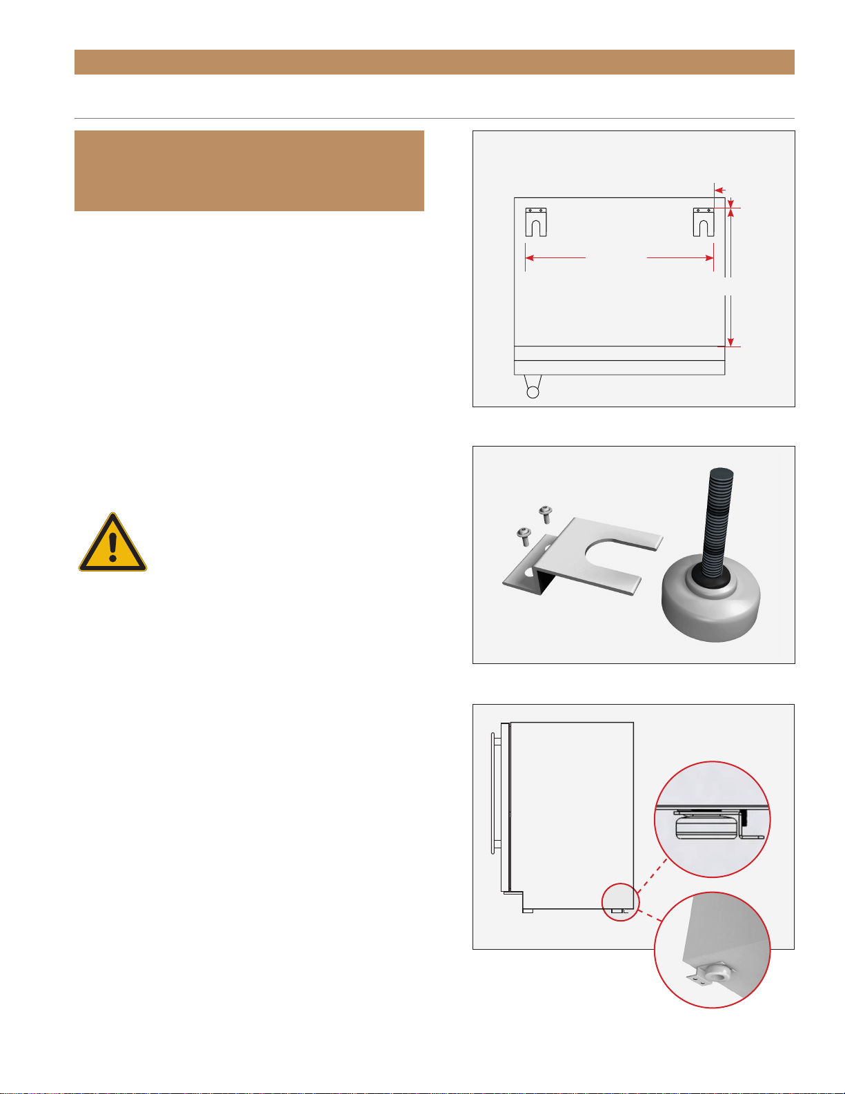
2. Determine the final installation location of the unit.
Measure 27/32" (22 mm) inset from the sides
and either 27/32" from the back or 18-1/2"
(470 mm) from the front (measure does not
include the kickplate). See fig. 1.
3. Position the anti-tip brackets and mark the
mounting hole locations.
4. With a 1/8” drill bit, drill pilot holes at the marked
locations.
NOTE: BE SURE TO USE A DRILL BIT
APPROPRIATE FOR YOUR FLOORING MATERIAL.
IMPORTANT!
ALL FREE STANDING DRAWER OR STACKED
UNITS MUST HAVE ANTI-TIP BRACKETS INSTALLED.
Anti-Tip Bracket (top view)
Back
Front
18-1/2"
22-3/16"
27/32"
FIG. 1.
Top plan view of anti-tip bracket positioning.
FIG. 2.
Securely fasten the anti-tip brackets to the floor.
FIG. 3.
Be sure the rear leveling legs slide into the brackets.
Loading ...
Loading ...
Loading ...