Loading ...
Loading ...
Loading ...
Position Drive Control levers
Thedrivecontrolleversof the ridingmowerareloweredfor shipping
purposes.The flangelocknuts,hex screws,andflatwashersthat
normallysecurethe controlleversintheir operatingpositionare
unfastenedand installedin the slottedholesof the controlleversfor
shipment.Thecontrolleversmustbe repositionedto operatethe
ridingmower.To repositionthe controlleversfor operation,proceedas
follows:
1. Removethehex screw,flat washer,andflangelocknut fromthe
slotof oneof the drivecontrollevers.
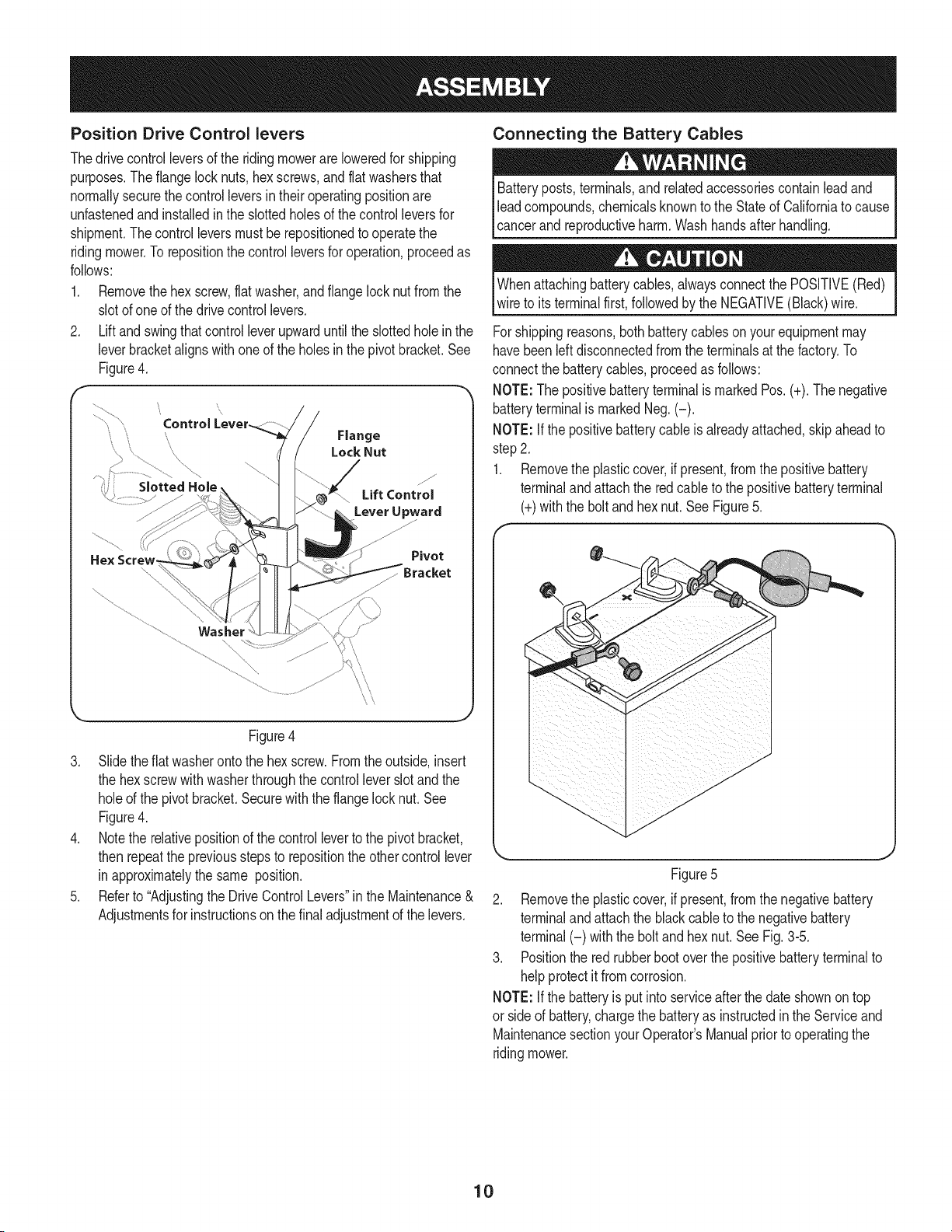
2. Liftand swingthat controlleverupwarduntilthe slottedhole in the
leverbracketalignswithoneof the holesinthe pivotbracket.See
Figure4.
\
Slotted Hole
Pivot
/
\
\\
\\
Figure4
3. Slidetheflat washerontothe hexscrew.Fromtheoutside,insert
the hexscrewwithwasherthroughthe controlleverslotand the
holeof the pivotbracket.Securewiththe flangelock nut. See
Figure4.
4. Notethe relativepositionof the controlleverto the pivotbracket,
then repeatthe previousstepsto repositionthe othercontrollever
inapproximatelythe same position.
5. Referto "Adjustingthe DriveControlLevers"inthe Maintenance&
Adjustmentsfor instructionsonthe finaladjustmentof the levers.
Connecting the Battery Cables
Batteryposts,terminals,and relatedaccessoriescontainleadand
leadcompounds,chemicalsknownto the Stateof Californiato cause
cancerand reproductiveharm. Washhandsafter handling.
Whenattachingbatterycables,alwaysconnectthe POSITIVE(Red)
wireto itsterminalfirst,followedby the NEGATIVE(Black)wire.
Forshippingreasons,bothbatterycableson yourequipmentmay
havebeenleft disconnectedfrom the terminalsat the factory.To
connectthe batterycables,proceedas follows:
NOTE:Thepositivebatteryterminalis markedPos.(+).The negative
batteryterminalis markedNeg.(-).
NOTE:If the positivebatterycable isalreadyattached,skipaheadto
step2.
1. Removethe plasticcover,ifpresent,from the positivebattery
terminalandattachthe red cableto the positivebatteryterminal
(+)withthe boltandhex nut.See Figure5.
Figure5
2. Removethe plasticcover,if present,from the negativebattery
terminalandattachthe blackcableto thenegativebattery
terminal(-) withthe boltand hexnut.SeeFig.3-5.
3. Positionthe red rubberbootoverthe positivebatteryterminalto
helpprotectitfromcorrosion.
NOTE:If the batteryis putintoserviceafterthe dateshownon top
or sideof battery,chargethe batteryas instructedinthe Serviceand
MaintenancesectionyourOperator'sManualpriortooperatingthe
ridingmower.
10
Loading ...
Loading ...
Loading ...