
perator_s nual
I:RRFrSMRN°
ZERO=TURN RIDER
24 Hi:), 42" MOWER DECK
Model No. 247,25001
CAUTION: Before using this product,
read this manual and follow all safety
rules and operating instructions,
o SAFETY
ASSEMBLY
OPERATION
MAINTENANCE
PARTS LIST
o ESPANOL
Sears Brands Management Corporation, Hoffman Estates, IL 60179, U.S.A.
Visit our website: www.craftsman.com
FormNo.769-07701
(November23,2011)
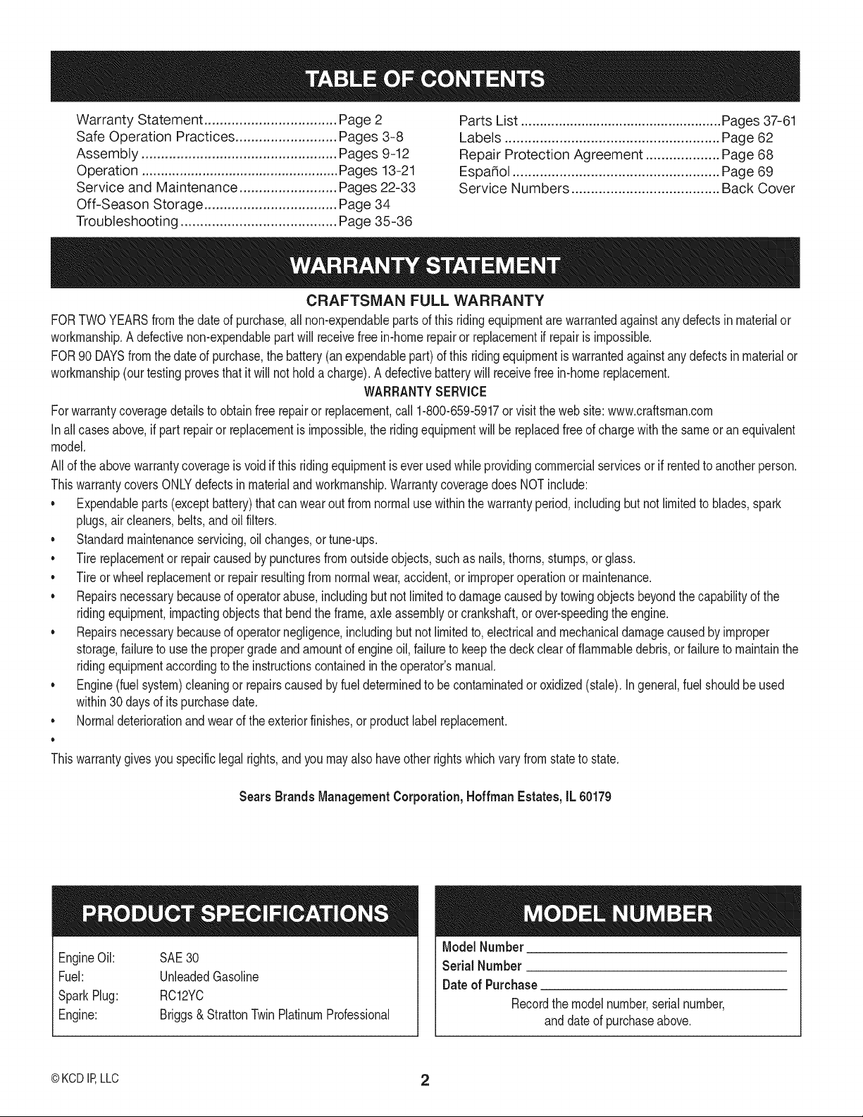
Warranty Statement .................................. Page 2
Safe Operation Practices .......................... Pages 3-8
Assembly .................................................. Pages 9-12
Operation .................................................... Pages 13-21
Service and Maintenance ......................... Pages 22-33
Off-Season Storage .................................. Page 34
Troubleshooting ........................................ Page 35-36
Parts List ..................................................... Pages 37-61
Labels ....................................................... Page 62
Repair Protection Agreement ................... Page 68
Espa_ol ..................................................... Page 69
Service Numbers ...................................... Back Cover
CRAFTSMAN FULL WARRANTY
FORTWOYEARSfromthe dateof purchase,all non-expendablepartsof this ridingequipmentarewarrantedagainstany defectsin materialor
workmanship.A defectivenon-expendablepartwill receivefree in-homerepairor replacementif repairis impossible.
FOR90 DAYSfromthe dateof purchase,the battery(anexpendablepart)of this ridingequipmentis warrantedagainstany defectsinmaterialor
workmanship(ourtestingprovesthat it will notholda charge).A defectivebatterywill receivefree in-homereplacement.
WARRANTYSERVICE
Forwarrantycoveragedetailsto obtainfree repairor replacement,call 1-800-659-5917or visitthe website: www.craftsman.com
In allcasesabove,if part repairor replacementis impossible,the ridingequipmentwill be replacedfreeof chargewiththe sameor anequivalent
model.
Allof the abovewarrantycoverageis void if thisridingequipmentis everusedwhileprovidingcommercialservicesor if rentedto anotherperson.
ThiswarrantycoversONLYdefectsin materialandworkmanship.Warrantycoveragedoes NOTinclude:
• Expendableparts(exceptbattery)that canwear outfrom normalusewithinthe warrantyperiod,includingbut not limitedto blades,spark
plugs,air cleaners,belts,andoilfilters.
• Standardmaintenanceservicing,oil changes,or tune-ups.
• Tire replacementor repaircausedby puncturesfromoutsideobjects,suchas nails,thorns,stumps,or glass.
• Tireor wheelreplacementor repairresultingfromnormalwear,accident,or improperoperationor maintenance.
• Repairsnecessarybecauseof operatorabuse,includingbutnot limitedto damagecausedby towingobjectsbeyondthe capabilityof the
ridingequipment,impactingobjectsthatbendthe frame,axle assemblyor crankshaft,orover-speedingthe engine.
• Repairsnecessarybecauseof operatornegligence,includingbutnot limitedto,electricalandmechanicaldamagecausedby improper
storage,failureto usethe propergradeand amountof engineoil,failureto keepthe deckclearof flammabledebris,orfailureto maintainthe
ridingequipmentaccordingto the instructionscontainedin theoperator'smanual.
• Engine(fuel system)cleaningor repairscausedbyfuel determinedto be contaminatedor oxidized(stale). Ingeneral,fuel shouldbeused
within30 daysof itspurchasedate.
Normaldeteriorationandwearof the exteriorfinishes,or productlabelreplacement.
o
o
Thiswarrantygivesyou specificlegalrights,and youmay alsohaveotherrights whichvary from stateto state.
Sears Brands ManagementCorporation, Hoffman Estates, IL 60179
EngineOil: SAE30
Fuel: UnleadedGasoline
SparkPlug: RC12YC
Engine: Briggs& StrattonTwinPlatinumProfessional
ModelNumber
Serial Number
Dateof Purchase
Recordthe modelnumber,serialnumber,
anddateof purchaseabove.
© KCD IRLLC 2
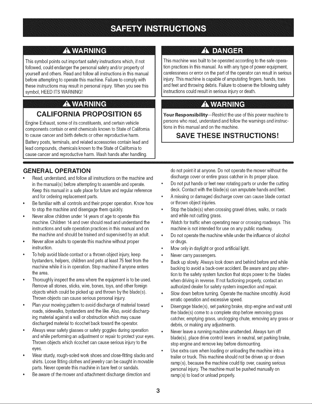
Thissymbolpointsout importantsafetyinstructionswhich,if not
followed,couldendangerthepersonalsafetyand/orpropertyof
yourselfandothers. Readandfollowall instructionsin this manual
beforeattemptingto operatethismachine.Failureto complywith
theseinstructionsmayresultin personalinjury.Whenyou seethis
symbol,HEEDITSWARNING!
CALIFORNIA PROPOSITION 65
EngineExhaust,someof itsconstituents,andcertainvehicle
componentscontainoremitchemicalsknownto Stateof California
to causecancerandbirthdefectsorother reproductiveharm.
Batteryposts,terminals,and relatedaccessoriescontainleadand
leadcompounds,chemicalsknownto the Stateof Californiato
causecancerandreproductiveharm.Washhandsafterhandling.
Thismachinewasbuiltto beoperatedaccordingto the safeopera-
tion practicesinthis manual.As withanytypeof powerequipment,
carelessnessorerroron the partof the operatorcan resultin serious
injury.Thismachineis capableof amputatingfingers,hands,toes
andfeetandthrowingdebris.Failureto observethe followingsafety
instructionscouldresultin seriousinjuryor death.
Your Responsibility--Restrict the use of this powermachineto
personswho read,understandandfollowthewarningsand instruc-
tionsin this manualand on the machine.
SAVE THESE INSTRUCTIONS!
GENERAL OPERATION
• Read,understand,andfollowall instructionson the machineand
in themanual(s)beforeattemptingto assembleandoperate.
Keepthis manualin a safe placefor futureand regularreference
andfor orderingreplacementparts.
• Befamiliarwithall controlsand their properoperation.Knowhow
to stopthe machineanddisengagethemquickly.
• Neverallowchildrenunder 14 yearsof age to operatethis
machine.Children14andover shouldreadandunderstandthe
instructionsandsafeoperationpracticesin thismanualandon
the machineandshouldbetrainedandsupervisedbyan adult.
• Neverallowadultsto operatethis machinewithoutproper
instruction.
• Tohelpavoidbladecontactor a thrownobjectinjury, keep
bystanders,helpers,childrenandpetsat least75feetfromthe
machinewhile it is in operation.Stopmachineif anyoneenters
the area.
• Thoroughlyinspectthe areawherethe equipmentis to be used.
Removeallstones,sticks,wire,bones,toys,andotherforeign
objectswhichcouldbe pickedup and thrownby the blade(s).
Thrownobjectscan causeseriouspersonalinjury.
• Planyour mowingpatternto avoiddischargeof materialtoward
roads,sidewalks,bystandersandthe like.Also,avoiddischarg-
ingmaterialagainstawall orobstructionwhichmaycause
dischargedmaterialto ricochetbacktowardthe operator.
• Alwayswearsafetyglassesor safetygogglesduringoperation
andwhileperforminganadjustmentor repairto protectyour eyes.
Thrownobjectswhichricochetcan causeseriousinjuryto the
eyes.
• Wearsturdy,rough-soledworkshoesandclose-fittingslacksand
shirts.Loosefittingclothesandjewelrycan becaughtin movable
parts.Neveroperatethis machinein barefeetor sandals.
• Beawareof the mowerandattachmentdischargedirectionand
do not pointit at anyone.Donot operatethe mowerwithoutthe
dischargecoverorentiregrasscatcherin its properplace.
• Donot put handsor feet near rotatingpartsor underthe cutting
deck. Contactwiththe blade(s)can amputatehandsandfeet.
A missingor damageddischargecovercan causebladecontact
or thrownobjectinjuries.
• Stoptheblade(s)whencrossinggraveldrives,walks,or roads
andwhile notcuttinggrass.
• Watchfor trafficwhenoperatingnear or crossingroadways.This
machineis not intendedfor useonany public roadway.
• Donot operatethe machinewhile underthe influenceof alcohol
or drugs.
• Mowonly in daylightor good artificiallight.
Nevercarrypassengers.
• Backup slowly.Alwayslookdown andbehindbeforeand while
backingto avoida back-overaccident.Beawareand payatten-
tion to the safetysystemfunctionthatstopspowerto the blades
whendrivingin reverse.If notfuctioningproperly,contactan
authorizeddealerfor safetysysteminspectionand repair.
• Slowdown beforeturning.Operatethe machinesmoothly.Avoid
erraticoperationandexcessivespeed.
Disengageblade(s),setparkingbrake,stopengineandwaituntil
the blade(s)cometo acompletestopbeforeremovinggrass
catcher,emptyinggrass,uncloggingchute,removingany grass or
debris,or makinganyadjustments.
• Neverleavea runningmachineunattended.Alwaysturn off
blade(s),placedrivecontrollevers inneutral,setparkingbrake,
stopengineand removekeybeforedismounting.
• Useextra carewhenloadingor unloadingthe machineinto a
traileror truck.Thismachineshouldnotbe drivenupor down
ramp(s),becausethe machinecouldtip over,causingserious
personalinjury.The machinemustbepushedmanuallyon
ramp(s)to loadorunloadproperly.
3
• Mufflerand engine becomehotand can causea burn.Do not
touch.
• Checkoverheadclearancescarefullybeforedrivingunderlow
hangingtree branches,wires,dooropeningsetc.,wherethe
operatormaybestruckor pulledfrom the machine,which could
resultinseriousinjury.
• Disengageallattachmentclutches,set the parkingbraketo the
'on' positionandmovethe RH and LHdrivecontrolleversto the
neutralpositionbeforeattemptingto startthe engine.
Yourmachineisdesignedto cutnormalresidentialgrassof a
heightnomorethan 10".Do not attemptto mowthroughunusually
tall,dry grass(e.g.,pasture)orpiles of dry leaves.Drygrassor
leavesmaycontactthe engineexhaustand/or build up on the
mowerdeckpresentinga potentialfire hazard.
• Useonlyaccessoriesandattachmentsapprovedfor this machine
by the machinemanufacturer.Read,understandandfollowall
instructionsprovidedwiththe approvedaccessoryor attachment.
Dataindicatesthatoperators,age 60 years and above,are
involvedin a largepercentageof ridingmower-relatedinjuries.
Theseoperatorsshouldevaluatetheirabilityto operatethe riding
mowersafelyenoughto protectthemselvesand othersfrom
seriousinjury.
• If situationsoccurwhich are not coveredin this manual,usecare
andgoodjudgment.Contactthe CraftsmanHelpLineat 1-800-
659-5917for assistance.
SLOPE OPERATION
Slopesarea majorfactorrelatedto lossof controlandtip-over
accidentswhichcan resultin severeinjuryor death.All slopes require
extracaution.If youcannot back up the slopeor if youfeel uneasyon
it, do not mowit.
Foryoursafety,use the slopegaugeincludedas part of thismanual
to measureslopesbeforeoperatingthis machineona slopedor hilly
area. Ifthe slopeis greaterthan15degreesas shownonthe slope
gauge,donot operatethis machineonthat area or seriousinjurycould
result.
Do:
o
Mowacrossslopes,not upanddown. Exerciseextremecaution
whenchangingdirectionon slopes.
Watchfor holes,ruts,bumps,rocks,orother hiddenobjects.
Uneventerraincouldoverturnthe machine.Tallgrasscan hide
obstacles.
Useslowspeed.Choosea lowenoughspeedso that youwill not
haveto stopwhileon the slope.Avoidstartingor stoppingon a
slope.If the tires are unableto maintaintraction,disengagethe
bladesandproceedslowlyand carefullystraightdownthe slope.
Followthe manufacturer'srecommendationsfor wheelweightsor
counterweightsto improvestability.
Useextracarewith grass catchersor otherattachments.These
can changethe stabilityof the machine.
• Keepall movementon the slopes slowand gradual.Do not
makesuddenchangesin speedor direction.Rapidacceleration
or decelerationcouldcausethe frontof the machineto lift and
rapidlyrollover backwards,whichcouldcauseseriousinjury.
DoNot:
• Donot turnon slopesunlessnecessary;thenturn slowlyuphill
and useextracarewhileturning.
• Donot mow neardrop-offs,ditchesor embankments.The mower
could suddenlyturnover if a wheelis overthe edgeof a cliff,
ditch,or if an edgecavesin.
• Donot try to stabilizethe machineby puttingyourfooton the
ground.
• Donot usea grass catcheron steepslopes.
• Donot mowon wet grass.Reducedtractioncouldcausesliding.
• Donot tow heavypull behindattachments(e.g.loadeddumpcart,
lawn roller,etc.)on slopesgreaterthan5 degrees.Whengoing
down hill,the extraweighttendsto pushthe ridingmowerand
maycauseyou to loosecontrol(e.g.ridingmowermay speed
up, brakingandsteeringabilityare reduced,attachmentmay
jack-knifeandcauseridingmowerto overturn).
4
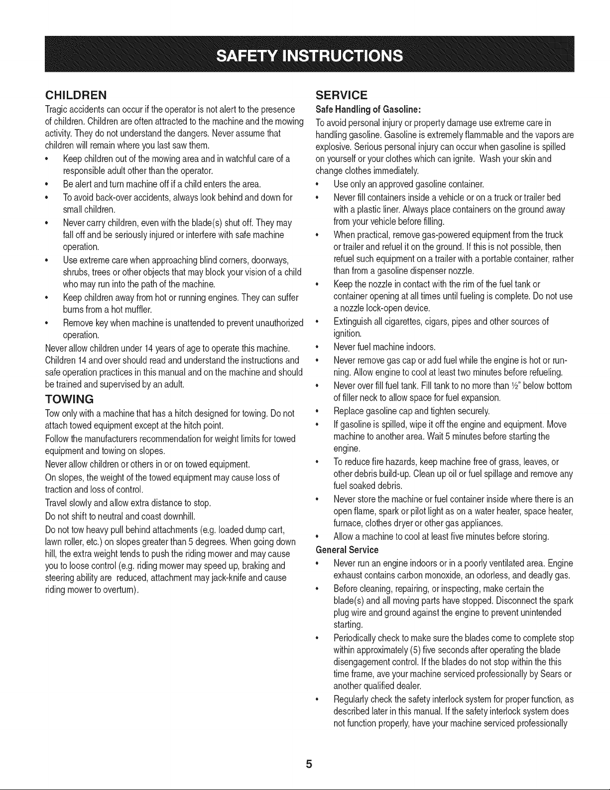
CHILDREN
Tragicaccidentscanoccurifthe operatoris notalert to the presence
of children.Childrenareoftenattractedto the machineandthe mowing
activity.Theydo notunderstandthe dangers.Neverassumethat
childrenwill remainwhereyou lastsawthem.
• Keepchildrenout of the mowingareaand inwatchfulcare of a
responsibleadultotherthanthe operator.
• Bealert and turnmachineoff ifa childentersthe area.
• Toavoidback-overaccidents,alwayslookbehindand downfor
smallchildren.
• Nevercarrychildren,evenwith the blade(s)shut off.They may
fall offandbe seriouslyinjuredor interferewithsafemachine
operation.
• Useextremecarewhenapproachingblind corners,doorways,
shrubs,treesor otherobjectsthat may block yourvisionof a child
whomayrunintothe pathof the machine.
• Keepchildrenaway from hotor runningengines.They cansuffer
burnsfroma hotmuffler.
• Removekeywhenmachineisunattendedto preventunauthorized
operation.
Neverallowchildrenunder14 yearsof age to operatethis machine.
Children14and overshouldreadand understandthe instructionsand
safeoperationpracticesinthismanualandon the machineandshould
betrainedand supervisedbyan adult.
TOWING
Towonlywitha machinethathasa hitch designedfor towing.Do not
attachtowedequipmentexceptat the hitchpoint.
Followthe manufacturersrecommendationforweightlimitsfortowed
equipmentandtowingonslopes.
Neverallowchildrenor othersinor on towedequipment.
Onslopes,theweightof thetowed equipmentmaycauselossof
tractionandloss of control.
Travelslowlyandallowextradistanceto stop.
Do not shiftto neutralandcoastdownhill.
Do nottowheavypull behindattachments(e.g.loadeddumpcart,
lawnroller,etc.) onslopesgreaterthan5 degrees.Whengoingdown
hill,the extraweighttendsto pushthe ridingmowerandmay cause
youto loosecontrol(e.g. ridingmowermayspeedup, brakingand
steeringabilityare reduced,attachmentmayjack-knifeand cause
ridingmowerto overturn).
SERVICE
SafeHandlingof Gasoline:
Toavoidpersonalinjuryorpropertydamageuse extremecarein
handlinggasoline.Gasolineisextremelyflammableand the vaporsare
explosive.Seriouspersonalinjurycanoccurwhengasolineis spilled
on yourselforyour clotheswhichcan ignite.Washyourskinand
changeclothesimmediately.
• Useonly an approvedgasolinecontainer.
• Neverfill containersinsidea vehicleoron a truckortrailer bed
witha plasticliner.Alwaysplacecontainerson the groundaway
fromyourvehiclebeforefilling.
• Whenpractical,removegas-poweredequipmentfromthe truck
or trailerandrefueliton theground.Ifthis isnot possible,then
refuelsuchequipmentona trailerwitha portablecontainer,rather
than froma gasolinedispensernozzle.
• Keepthe nozzleincontactwith the rim of the fueltank or
containeropeningat all timesuntilfuelingiscomplete.Donot use
a nozzlelock-opendevice.
• Extinguishall cigarettes,cigars,pipesand othersourcesof
ignition.
• Neverfuel machineindoors.
• Neverremovegascap or addfuelwhilethe engineis hotor run-
ning.Allowengineto coolat leasttwo minutesbeforerefueling.
• Neveroverfill fuel tank. Filltankto no morethan 1/2"belowbottom
of filler neckto allowspacefor fuelexpansion.
• Replacegasolinecap andtightensecurely.
• If gasolineis spilled,wipeitoff the engineand equipment.Move
machineto anotherarea.Wait5 minutesbeforestartingthe
engine.
• To reducefire hazards,keepmachinefree of grass,leaves,or
otherdebrisbuild-up.Cleanup oilor fuel spillageand removeany
fuel soakeddebris.
• Neverstorethe machineor fuelcontainerinsidewherethere isan
openflame,sparkor pilotlight as ona waterheater,spaceheater,
furnace,clothesdryeror othergasappliances.
• Allowa machineto coolat leastfive minutesbeforestoring.
GeneralService
• Neverrunan engineindoorsorina poorlyventilatedarea. Engine
exhaustcontainscarbonmonoxide,an odorless,and deadlygas.
• Beforecleaning,repairing,or inspecting,makecertainthe
blade(s)andall movingparts havestopped.Disconnectthe spark
plugwire andgroundagainsttheengineto preventunintended
starting.
• Periodicallycheckto makesurethe bladescometo completestop
withinapproximately(5) five secondsafter operatingthe blade
disengagementcontrol,ifthe bladesdonot stop withinthe this
timeframe,aveyourmachineservicedprofessionallyby Searsor
anotherqualifieddealer.
• Regularlycheckthesafetyinterlocksystemfor properfunction,as
describedlaterinthis manual.If the safetyinterlocksystemdoes
notfunctionproperly,haveyour machineservicedprofessionally
bySearsoranotherqualifieddealer.
• Checkthe blade(s)and engine mountingboltsat frequent
intervalsfor propertightness.Also,visuallyinspectblade(s)for
damage(e.g.,excessivewear,bent,cracked). Replacethe
blade(s)withtheoriginalequipmentmanufacturer's(O.E.M.)
blade(s)only,listedin this manual.Use of parts whichdo not
meetthe originalequipmentspecificationsmayleadto improper
performanceandcompromisesafety!
• Mowerbladesare sharp.Wrapthe blade or weargloves,and use
extracautionwhen servicingthem.
• Keepall nuts,bolts,and screwstight to be surethe equipmentis
in safeworkingcondition.
• Nevertamperwiththe safetyinterlocksystemor othersafety
devices.Checktheir properoperationregularly.
• Afterstrikinga foreignobject,stop the engine,disconnectthe
sparkplugwire(s) and groundagainstthe engine.Thoroughly
inspectthe machinefor anydamage.Repairthe damagebefore
startingandoperating.
• Neverattemptto makeadjustmentsor repairsto the machine
whilethe engineis running.
• Grasscatchercomponentsandthe dischargecoverare subject
to wearanddamagewhichcouldexposemovingpartsor allow
objectsto bethrown.Forsafetyprotection,frequentlycheck
componentsand replaceimmediatelywithoriginalequipment
manufacturer's(O.E.M.)partsonly,listedinthis manual.Use of
partswhichdo not meetthe originalequipmentspecificationsmay
leadto improperperformanceandcompromisesafety!
• Do notchangethe enginegovernorsettingsor over-speedthe
engine.The governorcontrolsthe maximumsafeoperatingspeed
of the engine.
• Maintainor replacesafetyand instructionlabels,as necessary.
• Observeproperdisposallawsandregulationsfor gas,oil, etc. to
protectthe environment.
• Accordingto the ConsumerProductsSafetyCommission(CPSC)
andthe U.S.EnvironmentalProtectionAgency(EPA),this product
hasan AverageUsefulLifeof seven(7)years,or 270 hoursof
operation.At theendof the AverageUsefulLifehavethe machine
inspectedannuallyby Searsor anotherqualifieddealerto ensure
thatall mechanicaland safetysystemsareworkingproperlyand
notworn excessively.Failureto do socan resultinaccidents,
injuriesor death.
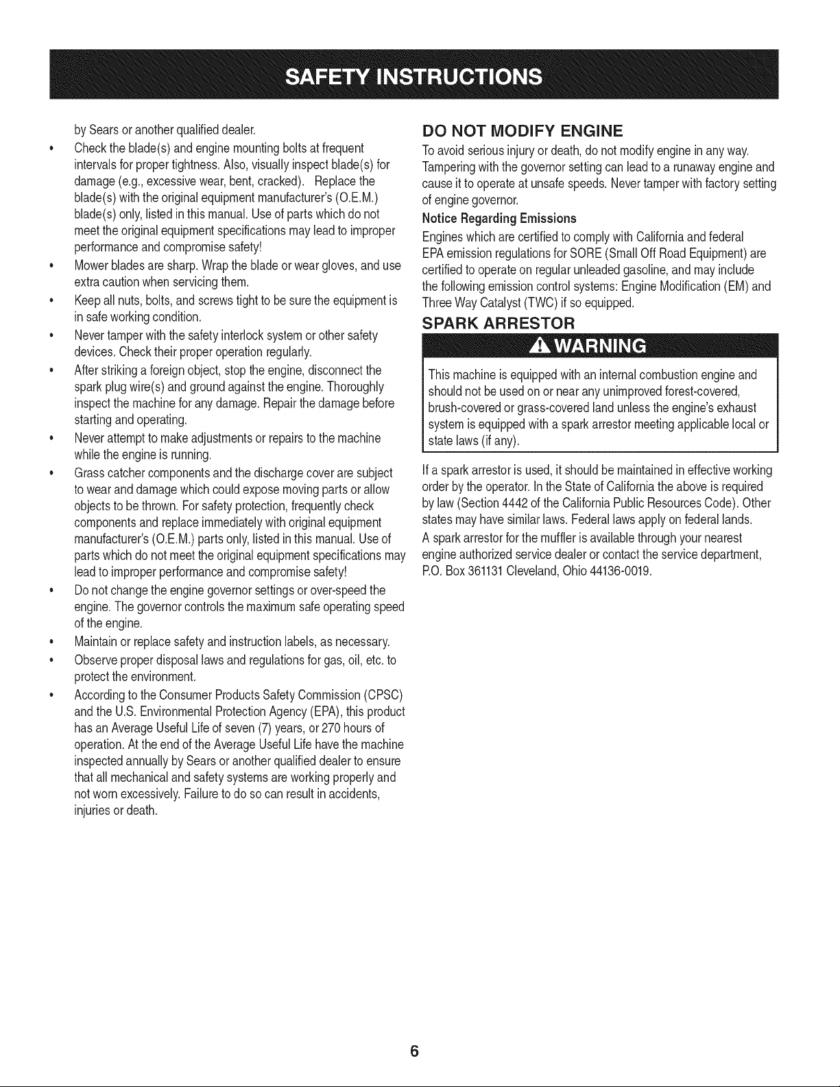
DO NOT MODIFY ENGINE
Toavoid seriousinjuryor death,do notmodifyengineinanyway.
Tamperingwiththe governorsettingcanleadto a runawayengineand
causeit to operateat unsafespeeds.Nevertamperwithfactorysetting
of enginegovernor.
Notice RegardingEmissions
Engineswhich are certifiedto complywith Californiaandfederal
EPAemissionregulationsfor SORE(SmallOffRoadEquipment)are
certifiedto operateon regularunleadedgasoline,andmayinclude
the followingemissioncontrolsystems:EngineModification(EM)and
ThreeWayCatalyst(TWO)if so equipped.
SPARK ARRESTOR
Thismachineis equippedwithan internalcombustionengineand
shouldnot beusedon or near anyunimprovedforest-covered,
brush-coveredor grass-coveredlandunlessthe engine'sexhaust
systemis equippedwitha sparkarrestormeetingapplicablelocalor
statelaws(if any).
Ifa sparkarrestoris used,it shouldbe maintainedin effectiveworking
orderby the operator.Inthe Stateof Californiatheaboveis required
by law (Section4442of the CaliforniaPublicResourcesCode).Other
statesmayhavesimilarlaws.Federallawsapplyonfederallands.
A sparkarrestorfor the muffleris availablethroughyournearest
engineauthorizedservicedealeror contactthe servicedepartment,
RO.Box361131Cleveland,Ohio 44136-0019.
6
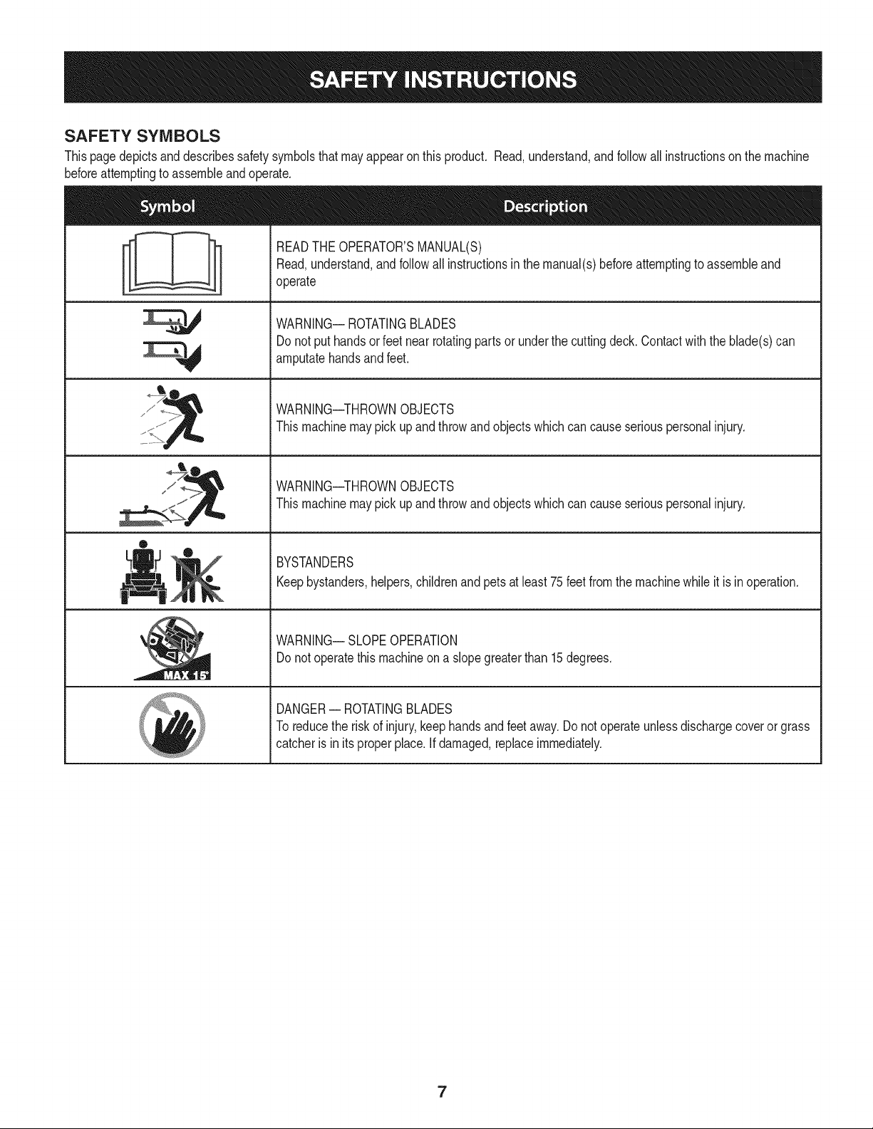
SAFETY SYMBOLS
Thispagedepictsanddescribessafety symbolsthatmay appearon this product. Read,understand,and follow all instructionson the machine
beforeattemptingto assembleandoperate.
sJ / _
®
READTHEOPERATOR'SMANUAL(S)
Read,understand,and followall instructionsin the manual(s)beforeattemptingto assembleand
operate
WARNING-- ROTATINGBLADES
Donot put handsor feetnearrotatingpartsor underthe cuttingdeck.Contactwith the blade(s)can
amputatehandsandfeet.
WARNING--THROWNOBJECTS
Thismachinemaypick up and throwand objectswhich cancause seriouspersonalinjury.
WARNING--THROWNOBJECTS
Thismachinemaypick up and throwand objectswhich cancause seriouspersonalinjury.
BYSTANDERS
Keepbystanders,helpers,childrenandpets at least 75 feet fromthe machinewhileit is in operation.
WARNING-- SLOPEOPERATION
Donot operatethismachineona slopegreaterthan 15 degrees.
DANGER-- ROTATINGBLADES
To reducethe riskof injury,keephandsandfeetaway.Donotoperateunlessdischargecoveror grass
catcheris in itsproperplace.If damaged,replaceimmediately.
7
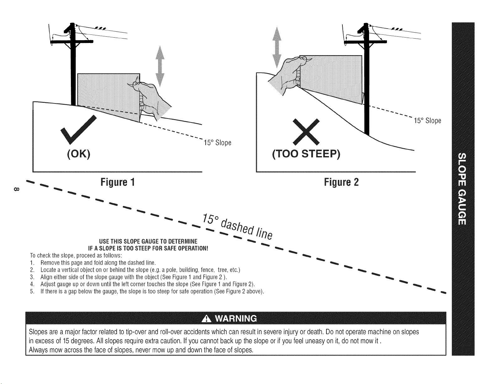
(OK)
15° Slope
X
(TOO STEEP)
15° Slope
'_. _ Figure1
USETHISSLOPEGAUGETODETERMINE
IFA SLOPEIS TOOSTEEPFORSAFEOPERATION!
To checkthe slope,proceedas follows:
1. Removethis pageandfold along the dashedline.
2. Locatea verticalobject onor behindthe slope (e.g.a pole, building,fence, tree, etc.)
3. Align eitherside of the slope gaugewith the object(SeeFigure1 and Figure2 ).
4. Adjust gaugeupor down until the left cornertouchesthe slope (SeeFigure1and Figure2).
5.
15°
dashed line
If there is agap belowthe gauge,the slope is too steepfor safeoperation(SeeFigure2 above).
Figure2
Slopes are a majorfactor related to tip-over and roll-over accidents which can result in severe injury or death. Do not operate machine on slopes
in excess of 15 degrees.All slopes require extra caution. If you cannot back up the slope or if you feel uneasy on it, do not mow it.
Always mow across the face of slopes, never mow up and down the face of slopes.
SET-UP
Moving The Riding mower Manually
Yourridingmower'stransmissionisequippedwitha hydrostaticrelief
valvefor occasionswhenit isnecessaryto movethe ridingmower
manually.Openingthisvalvepermitsthe fluid inthe transmissionto
bypassitsnormalroute,allowingthe reartiresto "freewheel."Toopen
the hydrostaticreliefvalve,proceedas follows:
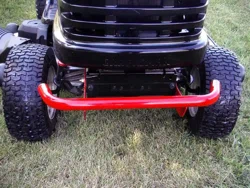
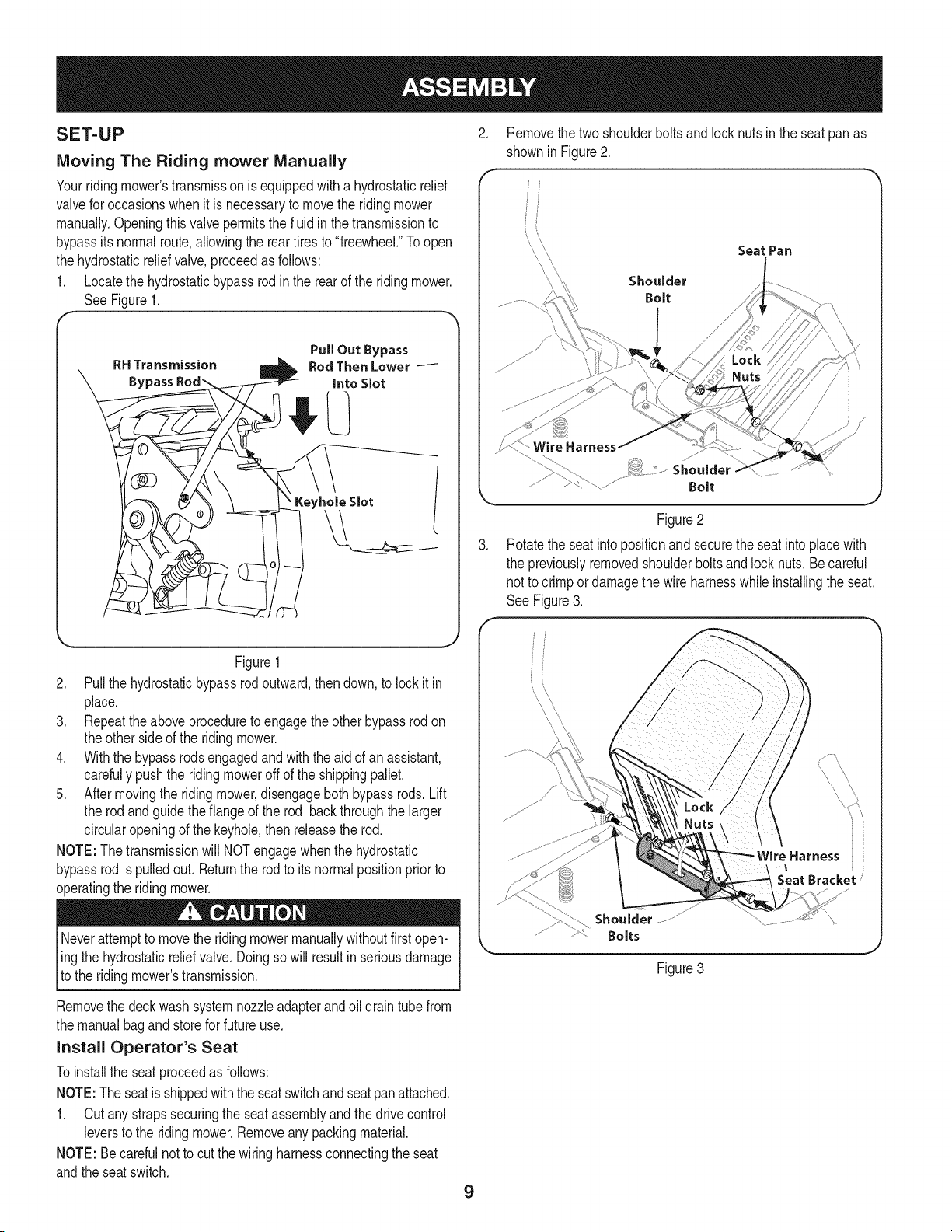
1. Locatethe hydrostaticbypassrod inthe rear of the ridingmower.
SeeFigure1.
RH Transmission
Bypass
PullOut Bypass
Rod ThenLower
Into Slot
Keyhole Slot
Figure1
2. Pullthe hydrostaticbypassrod outward,then down,to lock it in
place.
3. Repeattheaboveproceduretoengagethe otherbypassrod on
theother sideof the ridingmower.
4. Withthe bypassrodsengagedand with the aid of an assistant,
carefullypushthe ridingmoweroff of the shippingpallet.
5. Aftermovingthe ridingmower,disengageboth bypassrods. Lift
the rodandguidethe flangeof the rod backthroughthe larger
circularopeningof the keyhole,then releasethe rod.
NOTE:The transmissionwill NOTengagewhenthe hydrostatic
bypassrodis pulledout. Returnthe rodto itsnormalpositionpriorto
operatingthe ridingmower.
Neverattemptto movethe ridingmowermanuallywithoutfirstopen-
ling the hydrostaticr,elief valve.Doingso will resultin seriousdamage
[to the ridingmowers transmission.
Removethe deckwashsystemnozzleadapterandoil drain tube from
the manualbagand store forfuture use.
Install Operator's Seat
Toinstallthe seatproceedas follows:
NOTE:Theseatis shippedwiththe seatswitchandseatpanattached.
1. Cutanystrapssecuringthe seatassemblyand thedrivecontrol
leversto the ridingmower.Removeanypackingmaterial.
NOTE: Becarefulnotto cut thewiring harnessconnectingtheseat
andthe seat switch.
.
9
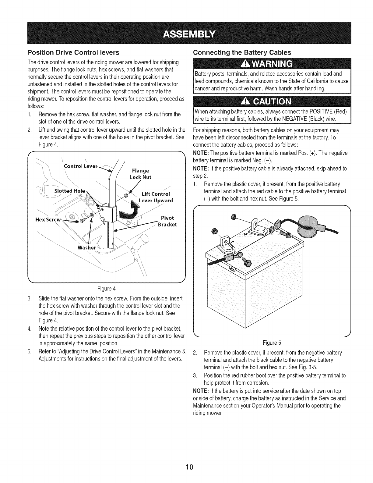
Removethe twoshoulderboltsand lock nuts in the seatpan as
shownin Figure2.
Shoulder
Bolt
Seat Pan
Shoulder
Bolt
Figure2
Rotatethe seatintopositionand securethe seatinto placewith
the previouslyremovedshoulderboltsand locknuts.Becareful
not to crimpordamagethe wire harnesswhile installingthe seat.
See Figure3.
iHarness ii
Seat Bracket /
Shoulder
Bolts
Figure 3
Position Drive Control levers
Thedrivecontrolleversof the ridingmowerareloweredfor shipping
purposes.The flangelocknuts,hex screws,andflatwashersthat
normallysecurethe controlleversintheir operatingpositionare
unfastenedand installedin the slottedholesof the controlleversfor
shipment.Thecontrolleversmustbe repositionedto operatethe
ridingmower.To repositionthe controlleversfor operation,proceedas
follows:
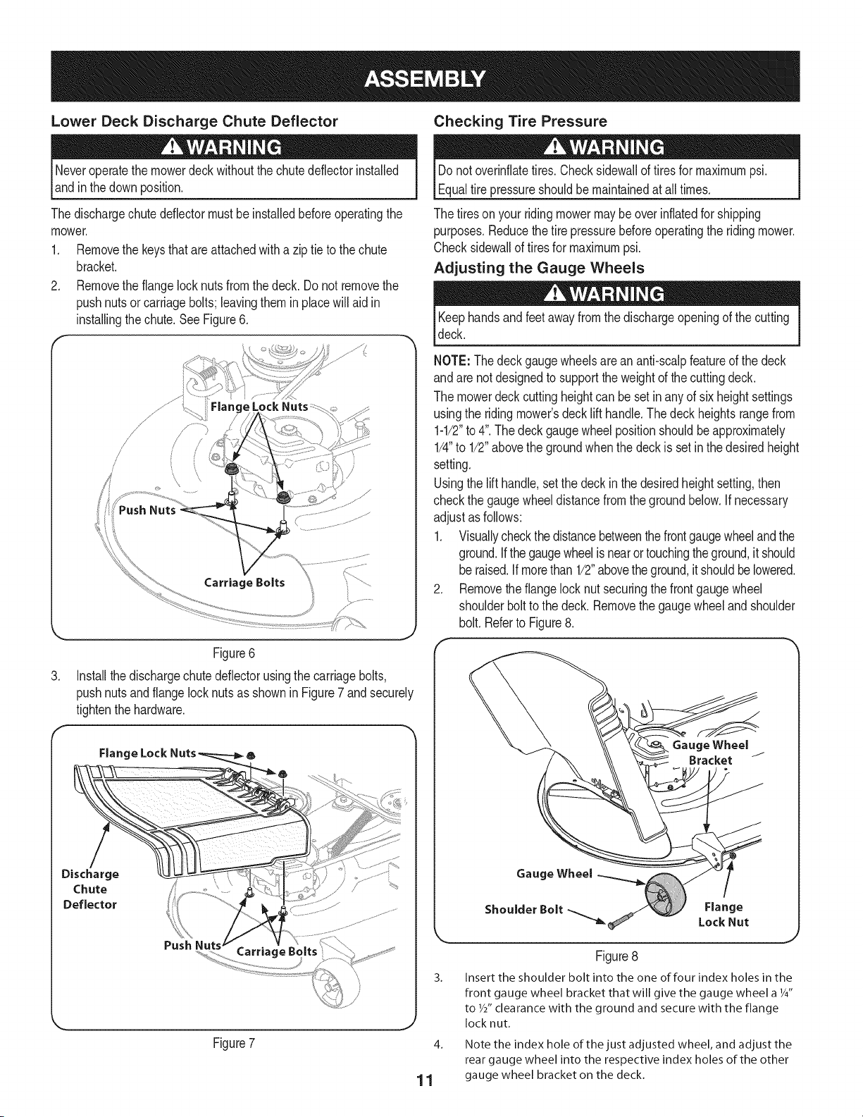
1. Removethehex screw,flat washer,andflangelocknut fromthe
slotof oneof the drivecontrollevers.
2. Liftand swingthat controlleverupwarduntilthe slottedhole in the
leverbracketalignswithoneof the holesinthe pivotbracket.See
Figure4.
\
Slotted Hole
Pivot
/
\
\\
\\
Figure4
3. Slidetheflat washerontothe hexscrew.Fromtheoutside,insert
the hexscrewwithwasherthroughthe controlleverslotand the
holeof the pivotbracket.Securewiththe flangelock nut. See
Figure4.
4. Notethe relativepositionof the controlleverto the pivotbracket,
then repeatthe previousstepsto repositionthe othercontrollever
inapproximatelythe same position.
5. Referto "Adjustingthe DriveControlLevers"inthe Maintenance&
Adjustmentsfor instructionsonthe finaladjustmentof the levers.
Connecting the Battery Cables
Batteryposts,terminals,and relatedaccessoriescontainleadand
leadcompounds,chemicalsknownto the Stateof Californiato cause
cancerand reproductiveharm. Washhandsafter handling.
Whenattachingbatterycables,alwaysconnectthe POSITIVE(Red)
wireto itsterminalfirst,followedby the NEGATIVE(Black)wire.
Forshippingreasons,bothbatterycableson yourequipmentmay
havebeenleft disconnectedfrom the terminalsat the factory.To
connectthe batterycables,proceedas follows:
NOTE:Thepositivebatteryterminalis markedPos.(+).The negative
batteryterminalis markedNeg.(-).
NOTE:If the positivebatterycable isalreadyattached,skipaheadto
step2.
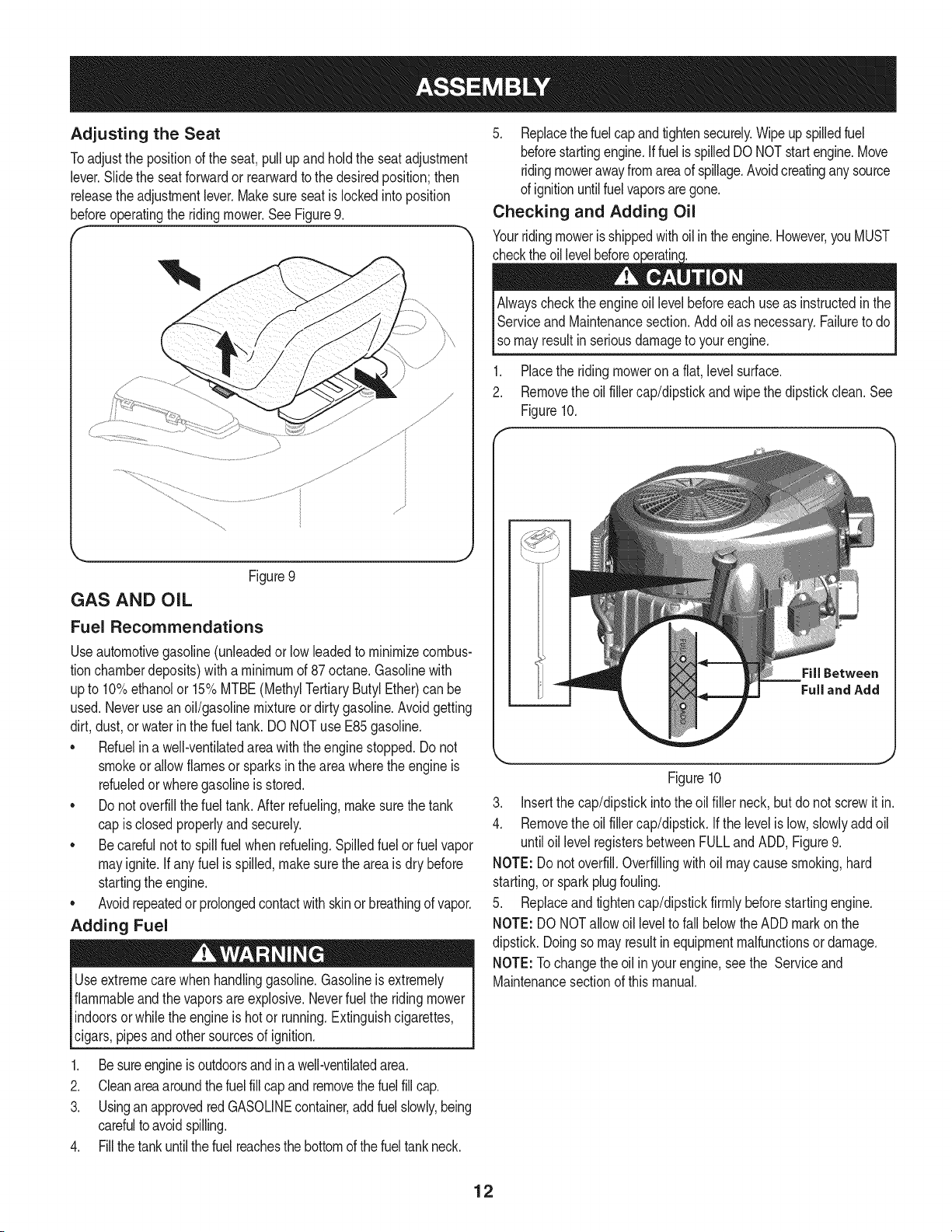
1. Removethe plasticcover,ifpresent,from the positivebattery
terminalandattachthe red cableto the positivebatteryterminal
(+)withthe boltandhex nut.See Figure5.
Figure5
2. Removethe plasticcover,if present,from the negativebattery
terminalandattachthe blackcableto thenegativebattery
terminal(-) withthe boltand hexnut.SeeFig.3-5.
3. Positionthe red rubberbootoverthe positivebatteryterminalto
helpprotectitfromcorrosion.
NOTE:If the batteryis putintoserviceafterthe dateshownon top
or sideof battery,chargethe batteryas instructedinthe Serviceand
MaintenancesectionyourOperator'sManualpriortooperatingthe
ridingmower.
10
Lower Deck Discharge Chute Deflector Checking Tire Pressure
Neveroperatethe mowerdeckwithoutthe chutedeflectorinstalled
andin the downposition.
Thedischargechutedeflectormustbe installedbeforeoperatingthe
mower.
1. Removethe keysthat are attachedwith a zip tie to the chute
bracket.
2. Removethe flangelock nuts from thedeck. Do not removethe
pushnutsor carriagebolts;leavingthem in placewill aid in
installingthe chute.SeeFigure6.
,//
/
/
/
/
/
Carriage Bolts
Figure6
3. Installthedischargechutedeflectorusingthe carriagebolts,
pushnutsand flangelock nuts as shownin Figure7 and securely
tightenthe hardware.
Flange Lock 6
Discharge
Chute
Deflector
Push
Carriage Bc
Figure7
J
Donot overinflatetires.Checksidewallof tiresfor maximumpsi.
Equaltire pressureshouldbe maintainedat all times.
The tiresonyour ridingmowermaybe overinflatedfor shipping
purposes.Reducethetire pressurebeforeoperatingthe ridingmower.
Checksidewallof tiresfor maximumpsi.
Adjusting the Gauge Wheels
Keephandsandfeet awayfrom the dischargeopeningof the cutting
deck.
NOTE: Thedeckgaugewheelsarean anti-scalpfeatureof the deck
andare notdesignedto supportthe weightof the cuttingdeck.
The mowerdeckcuttingheightcan be set in anyof six heightsettings
usingthe ridingmower'sdecklift handle.The deckheightsrangefrom
1-1/2"to 4".The deckgaugewheelpositionshouldbeapproximately
1/4"to 1/2"abovethe groundwhenthe deck is set in thedesiredheight
setting.
Usingthe lifthandle,setthe deck in the desiredheightsetting,then
checkthe gaugewheeldistancefromthe groundbelow.If necessary
adjustasfollows:
1. Visuallycheckthe distancebetweenthefrontgaugewheelandthe
ground.Ifthe gaugewheelis nearortouchingtheground,it should
be raised.If morethan1/2"abovetheground,it shouldbe lowered.
2. Removethe flangelock nut securingthe frontgauge wheel
shoulderboltto the deck.Removethe gaugewheelandshoulder
bolt. Referto Figure8.
Gauge Wheel
3_
Gauge Wheel
Flange
ShoulderBolt _ LockNut
Figure8
Insert the shoulder bolt into the one of four index holes in the
front gauge wheel bracket that will give the gauge wheel a Y4"
to W' clearance with the ground and secure with the flange
locknut.
4. Note the index hole of the just adjusted wheel, and adjust the
rear gauge wheel into the respective index holes of the other
1 1 gauge wheel bracket on the deck.
Adjusting the Seat
Toadjustthe positionof the seat,pullup and holdthe seatadjustment
lever.Slidethe seatforwardor rearwardto the desiredposition;then
releasethe adjustmentlever.Makesureseatislockedintoposition
beforeoperatingthe ridingmower.See Figure9.
m J
Figure9
GAS AND OIL
Fuel Recommendations
Useautomotivegasoline(unleadedor low leadedto minimizecombus-
tionchamberdeposits)witha minimumof 87octane.Gasolinewith
upto 10%ethanolor 15%MTBE(MethylTertiaryButylEther)can be
used.Neveruse anoil/gasolinemixtureor dirtygasoline.Avoidgetting
dirt,dust,or waterin the fueltank. DONOTuse E85gasoline.
• Refuelina well-ventilatedareawith the enginestopped.Donot
smokeor allowflamesor sparksinthe areawherethe engineis
refueledorwheregasolineis stored.
Do notoverfillthe fuel tank.Afterrefueling,makesurethetank
cap is closedproperlyand securely.
Becarefulnot to spill fuelwhen refueling.Spilledfuel or fuelvapor
mayignite.Ifany fuel is spilled,makesurethe areais dry before
startingthe engine.
Avoidrepeatedor prolongedcontactwithskinor breathingof vapor.
Adding Fuel
Useextremecarewhenhandlinggasoline.Gasolineisextremely
flammableandthe vaporsareexplosive.Neverfuelthe ridingmower
indoorsor whilethe engineis hot or running.Extinguishcigarettes,
cigars,pipesand othersourcesof ignition.
1. Besureengineis outdoorsandin a well-ventilatedarea.
2. Cleanareaaroundthefuelfillcap and removethe fuelfillcap.
3. Usingan approvedredGASOLINEcontainer,addfuel slowly,being
carefulto avoidspilling.
4. Fillthetankuntilthefuel reachesthe bottomof the fueltankneck.
5. Replacethefuel capand tightensecurely.Wipeup spilledfuel
beforestartingengine.Iffuelis spilledDO NOTstartengine.Move
ridingmowerawayfromareaof spillage.Avoidcreatinganysource
of ignitionuntilfuelvaporsaregone.
Checking and Adding Oil
Yourridingmoweris shippedwithoilinthe engine.However,youMUST
checkthe engineoil levelbeforeeach useas instructedin the IAlways
Serviceand Maintenancesection.Add oil as necessary.Failureto do I
I
[so mayresut nser ous damageto youreng ne. J
1. Placethe riding moweron a flat,level surface.
2. Removethe oil filler cap/dipstickand wipe thedipstickclean. See
Figure10.
Figure10
3. Insertthe cap/dipstickintothe oil filler neck,but do not screwit in.
4. Removethe oil filler cap/dipstick.If the levelis low,slowlyadd oil
untiloillevel registersbetweenFULLandADD,Figure9.
NOTE:Do notoverfill.Overfillingwithoil maycausesmoking,hard
starting,or sparkplugfouling.
5. Replaceand tightencap/dipstickfirmly beforestartingengine.
NOTE:DO NOTallowoil levelto fall belowthe ADDmarkonthe
dipstick.Doingso mayresultinequipmentmalfunctionsor damage.
NOTE:Tochangethe oil inyour engine,seethe Serviceand
Maintenancesectionof thismanual.
12
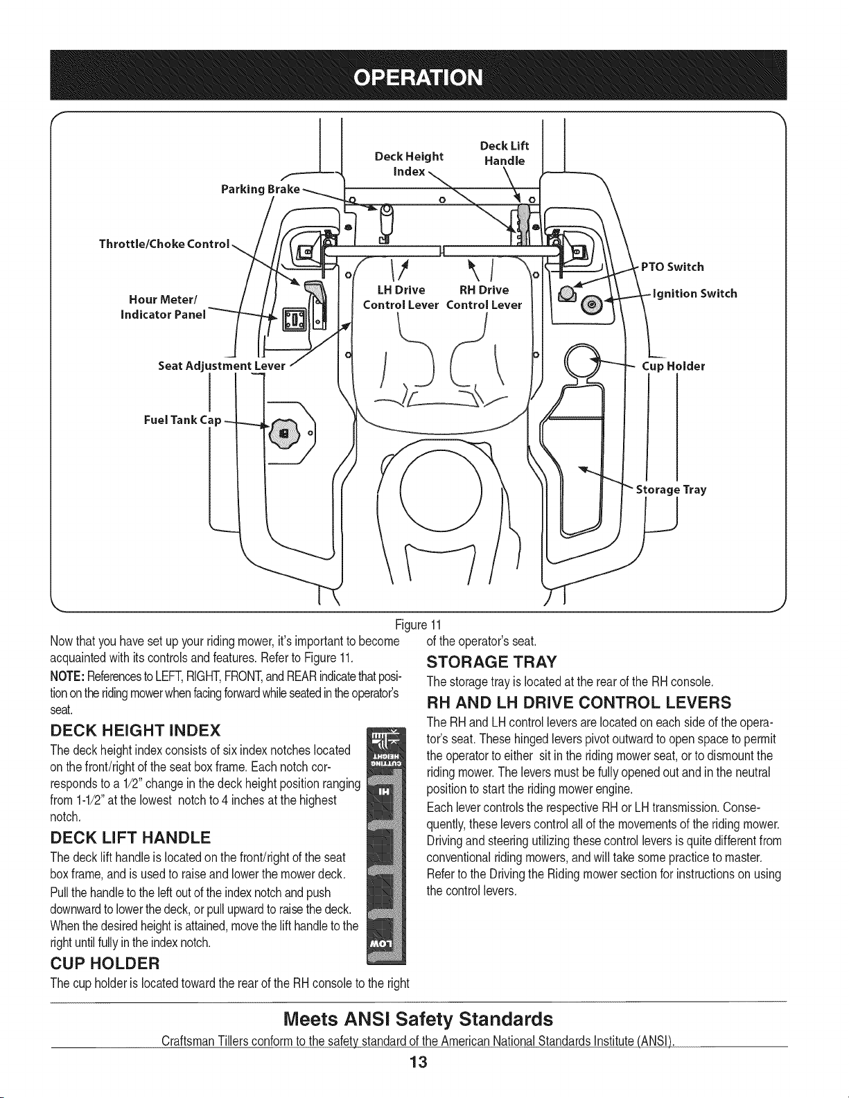
Parking
Deck Lift
Deck Height Handle
O
Throttle/Choke Control
Hour Meter/
indicator Panel
SeatAdjustmentLever
FuelTankCap
H
// _ / -PTOSwitch
LH Drive RH Drive nition Switch
Control Lever Control Lever
Cup Holder
Storage Tray
Figure11
Nowthat youhavesetup yourridingmower,it'simportantto become of the operator'sseat.
acquaintedwith itscontrolsandfeatures.Referto Figure11.
NOTE:Referencesto LEFT,RIGHT,FRONT,andREARindicatethatposi-
tionontheridingmowerwhenfacingforwardwhileseatedintheoperator's
seat.
DECK HEIGHT iNDEX
Thedeckheightindexconsistsof sixindexnotcheslocated
onthe front/rightof the seat boxframe.Eachnotchcor-
respondsto a 1/2"changein thedeck heightpositionranging
from1-1/2"at the lowest notchto 4 inchesat the highest
notch.
DECK LiFT HANDLE
Thedecklift handleis locatedon the front!rightof the seat
boxframe,andisusedto raiseand lowerthe mowerdeck.
Pullthe handleto the leftoutof the indexnotchandpush
downwardto lowerthedeck,or pullupwardto raisethe deck.
Whenthedesiredheightisattained,movethe lifthandleto the
rightuntilfullyinthe indexnotch.
CUP HOLDER
Thecup holderis locatedtowardthe rearof the RHconsoleto the right
STORAGE TRAY
The storagetrayislocatedat the rearof the RHconsole.
RH AND LH DRIVE CONTROL LEVERS
The RHandLH controlleversarelocatedon eachsideof the opera-
tor's seat.Thesehingedleverspivotoutwardto openspaceto permit
the operatorto either sit in the ridingmowerseat,or to dismountthe
ridingmower.Theleversmust befullyopenedoutand in the neutral
positionto startthe ridingmowerengine.
Eachlevercontrolsthe respectiveRHorLH transmission.Conse-
quently,theseleverscontrolallof the movementsof the ridingmower.
Drivingand steeringutilizingthesecontrolleversis quitedifferentfrom
conventionalriding mowers,andwill takesomepracticeto master.
Referto the Drivingthe Ridingmowersectionfor instructionsonusing
the controllevers.
Meets ANSi Safety Standards
CraftsmanTillersconformto the safetystandardof the AmericanNationalStandardsInstitute(ANSI)
13
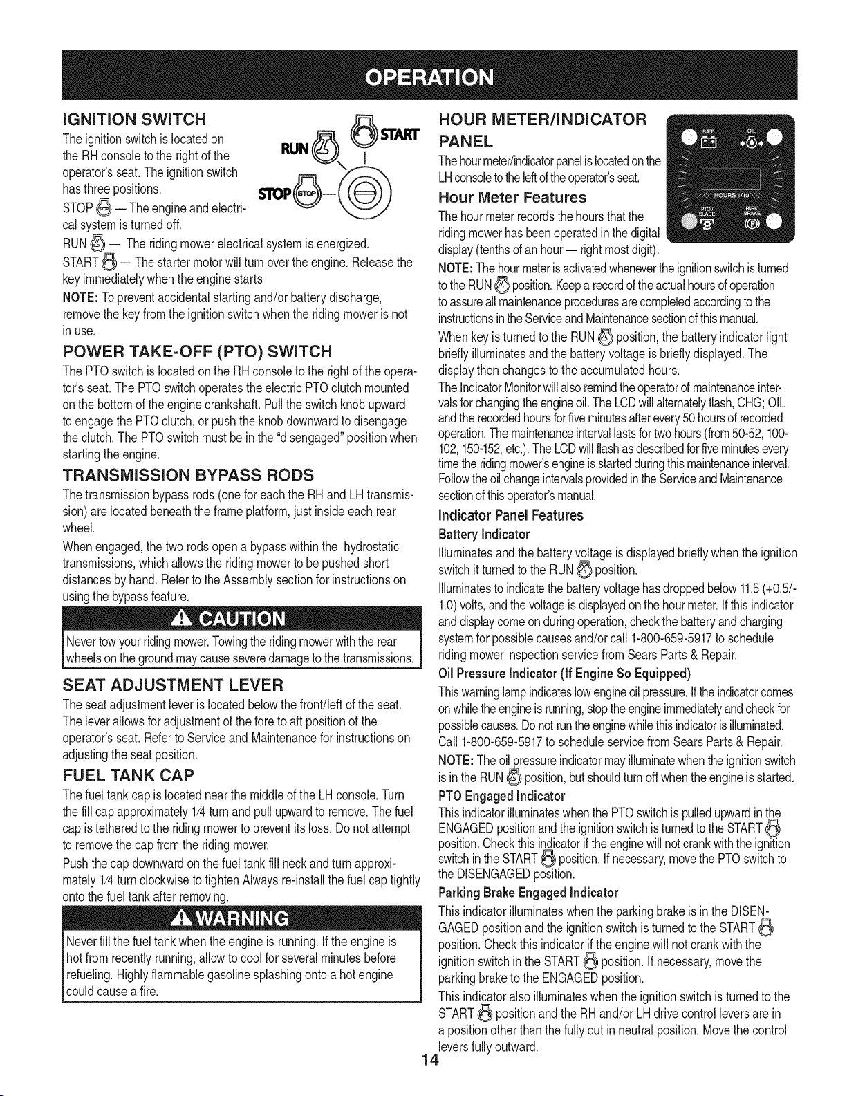
iGNiTiON SWITCH
Theignitionswitchis locatedon
the RHconsoleto the rightof the
operator'sseat.Theignitionswitch
hasthree positions.
STOP_ -- Theengine and electri-
cal systemis turnedoff.
RUN_ I
RUN_ -- The ridingmowerelectricalsystemisenergized.
START_ -- The startermotorwill turn overtheengine.Releasethe
keyimmediatelywhenthe enginestarts
NOTE:Topreventaccidentalstartingand/or batterydischarge,
removethe keyfromthe ignitionswitchwhenthe ridingmowerisnot
inuse.
POWER TAKE-OFF (PTO) SWITCH
The PTOswitchislocatedonthe RH consoleto the rightof the opera-
tor's seat.The PTOswitchoperatestheelectric PTOclutchmounted
onthe bottomof theenginecrankshaft.Pullthe switchknobupward
to engagethe PTOclutch,or pushtheknob downwardto disengage
the clutch.The PTOswitchmustbeinthe "disengaged"positionwhen
startingthe engine.
TRANSMiSSiON BYPASS RODS
Thetransmissionbypassrods(onefor eachthe RHandLH transmis-
sion)arelocatedbeneaththe frame platform,justinsideeach rear
wheel.
Whenengaged,the two rodsopen a bypasswithinthe hydrostatic
transmissions,whichallowsthe ridingmowerto be pushedshort
distancesby hand.Referto the Assemblysectionfor instructionson
usingthe bypassfeature.
Nevertowyourridingmower.Towingthe ridingmowerwiththe rear
wheelsonthe groundmaycauseseveredamageto thetransmissions.
SEAT ADJUSTMENT LEVER
Theseatadjustmentleveris locatedbelowthefront!leftof the seat.
Theleverallowsfor adjustmentof the foreto aft positionof the
operator'sseat.Referto Serviceand Maintenancefor instructionson
adjustingthe seatposition.
FUEL TANK CAP
Thefuel tankcap islocatednearthe middleof the LH console.Turn
the fill capapproximately1/4turnandpull upwardto remove.The fuel
cap istetheredto the ridingmowerto preventitsloss.Do notattempt
to removethe cap fromthe ridingmower.
Pushthecap downwardonthe fuel tankfill neckand turnapproxi-
mately1/4turn clockwiseto tightenAlwaysre-installthe fuelcap tightly
ontothe fueltankafter removing.
Neverfill the fueltankwhenthe engineis running.Ifthe engineis
hotfrom recentlyrunning,allowto coolfor severalminutesbefore
refueling.Highlyflammablegasolinesplashingontoa hot engine
couldcausea fire.
HOUR METER/INDICATOR
PANEL
Thehourmeter/indicatorpanelis locatedonthe
LHconsoletotheIdtd theoperator'sseat.
Hour Meter Features
The hourmeterrecordsthe hoursthatthe
ridingmowerhasbeenoperatedinthe digital
display(tenthsof anhour-- rightmostdigit).
NOTE:The hourmeteris activatedwhenevertheignitionswitchisturned
to theRUN_ position.Keepa recordof theactualhoursof operation
to assureallmaintenanceproceduresarecompletedaccordingtothe
instructionsintheServiceandMaintenancesectionof thismanual.
Whenkeyis turnedto the RUN_ position,the batteryindicatorlight
brieflyilluminatesandthe batteryvoltageis brieflydisplayed.The
displaythen changesto the accumulatedhours.
TheIndicatorMonitorwillalsoremindtheoperatorofmaintenanceinter-
valsforchangingtheengineoil.TheLCDwillalternatelyflash,CHG;OIL
andthe recordedhoursforfiveminutesafterevery50hoursof recorded
operation.Themaintenanceintervallastsfortwohours(from50-52,100-
102,150-152,etc.).The LCDwillflashasdescribedforfiveminutesevery
timethe ridingmower'sengineis startedduringthismaintenanceinterval.
FollowtheoilchangeintervalsprovidedintheServiceandMaintenance
sectionof thisoperator'smanual.
indicator Panel Features
Battery Indicator
Illuminatesandthe batteryvoltageis displayedbrieflywhenthe ignition
switchit turnedto the RUN_ position.
Illuminatesto indicatethe batteryvoltagehasdroppedbelow11.5(+0.5/-
1.0)volts,andthe voltageis displayedonthe hourmeter.Ifthisindicator
anddisplaycomeonduringoperation,checkthe batteryandcharging
systemforpossiblecausesand/orcall 1-800-659-5917to schedule
ridingmowerinspectionservicefromSearsParts & Repair.
Oil PressureIndicator (if EngineSo Equipped)
Thiswarninglampindicateslowengineoilpressure.Iftheindicatorcomes
onwhiletheengineis running,stoptheengineimmediatelyandcheckfor
possiblecauses.Donotruntheenginewhilethisindicatorisilluminated.
Call1-800-659-5917to scheduleservicefrom SearsParts & Repair.
NOTE:Theoil_ressureindicatormayilluminatewhenthe ignitionswitch
isin the RUN0 position,butshouldturnoffwhentheengineis started.
PTOEngagedIndicator
Thisindicatorilluminateswhenthe PTOswitchis pulledupwardinthe
ENGAGEDpositionandthe ignitionswitchis turnedtothe START
position.Checkthisindicatorif theenginewillnotcrankwiththeignition
switchinthe START_ position.Ifnecessary,movethe PTOswitchto
the DISENGAGEDposition.
ParkingBrake Engaged Indicator
Thisindicatorilluminateswhenthe parkingbrakeis in the DISEN-
GAGEDpositionandthe ignitionswitchis turnedtothe START
position.Checkthis indicatorif the enginewill not crankwiththe
ignitionswitchin the START_ position.If necessary,move the
parkingbraketo the ENGAGEDposition.
Thisindicatoralsoilluminateswhenthe ignitionswitchis turnedto the
START_ positionandthe RH and/or LHdrivecontrolleversare in
a positionotherthanthe fullyout in neutralposition.Movethe control
leversfullyoutward.
14
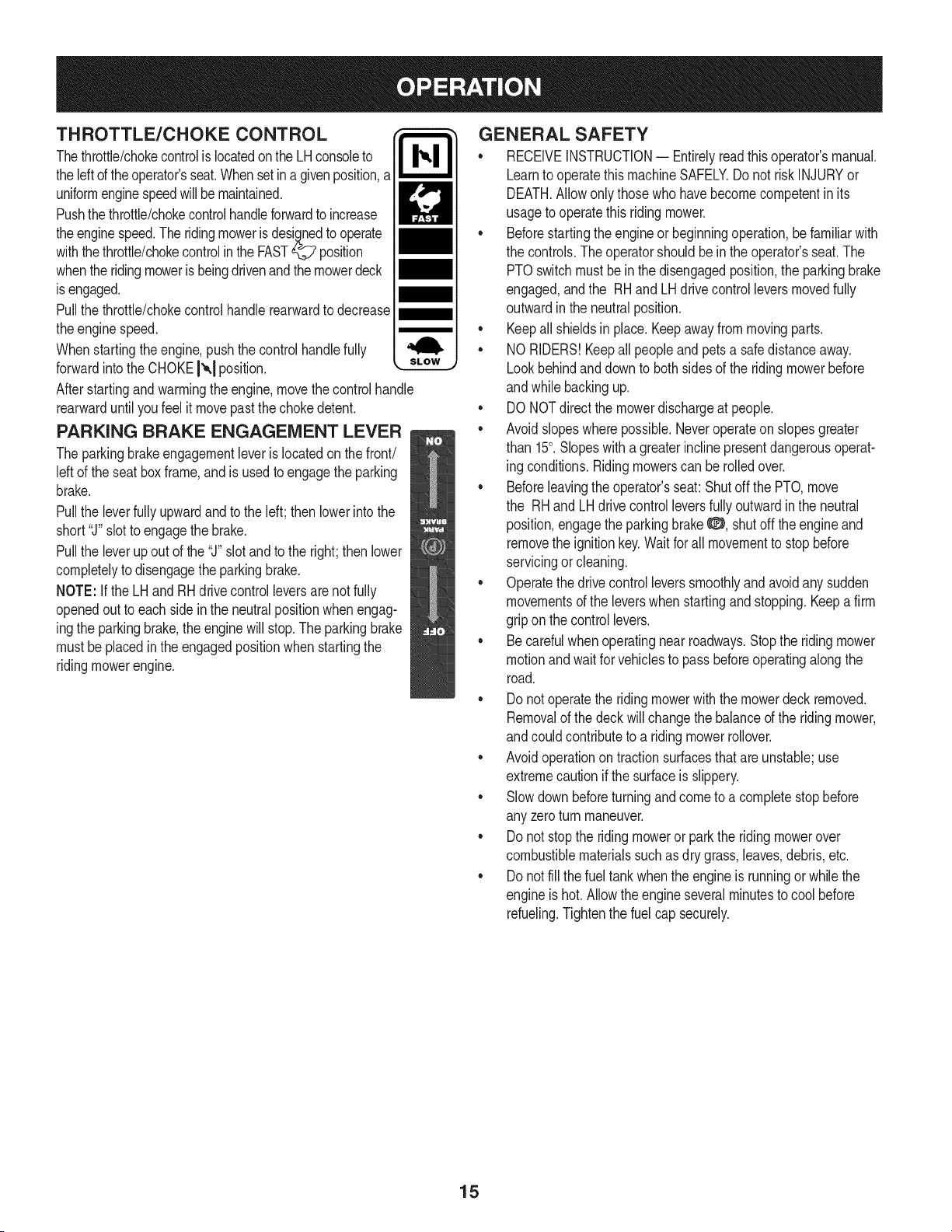
THROTTLE/CHOKE CONTROL
Thethrottle/chokecontrolis locatedonthe LHconsoleto
theleftof theoperator'sseat.Whensetina givenposition,a
uniformenginespeedwill be maintained.
Pushthe throttle/chokecontrolhandleforwardto increase
theenginespeed.The ridingmowerisdesignedto operate
withthe throttle/chokecontrolinthe FAST_ position
whenthe ridingmoweris beingdrivenandthe mowerdeck
is engaged.
Pullthe throttle/chokecontrolhandlerearwardto decrease
theenginespeed.
Whenstartingthe engine,push thecontrolhandlefully
forwardintothe CHOKEI'_,1position.
Afterstartingand warmingtheengine,movethe controlhandle
rearwarduntilyoufeel it movepastthechokedetent.
PARKING BRAKE ENGAGEMENT LEVER
The parkingbrakeengagementleveris locatedonthe front/
leftof the seatboxframe,andis usedto engagethe parking
brake.
Pullthe leverfullyupwardandtothe left;then lowerintothe
short"J"slotto engagethe brake.
Pullthe leverupout of the"J" slot andto the right;then lower
completelyto disengagethe parkingbrake.
NOTE: Ifthe LH andRHdrivecontrolleversarenot fully
openedoutto eachsidein the neutralpositionwhenengag-
ingthe parkingbrake,the enginewill stop.The parkingbrake
mustbe placedin the engagedpositionwhenstartingthe
ridingmowerengine.
GENERAL SAFETY
• RECEIVEINSTRUCTION-- Entirelyreadthisoperator'smanual.
Learnto operatethismachineSAFELY.Do not riskINJURYor
DEATH.Allowonlythosewho havebecomecompetentin its
usageto operatethis ridingmower.
• Beforestartingthe engineor beginningoperation,be familiarwith
the controls.Theoperatorshouldbein the operator'sseat.The
PTOswitchmustbein the disengagedposition,the parkingbrake
engaged,andthe RHand LHdrivecontrolleversmovedfully
outwardin the neutralposition.
• Keepall shieldsin place. Keepawayfrom movingparts.
• NORIDERS!Keepall peopleand pets a safedistanceaway.
Lookbehindand downto bothsidesof the ridingmowerbefore
andwhile backingup.
• DONOTdirect the mowerdischargeat people.
• Avoidslopeswherepossible.Neveroperateon slopesgreater
than 15°. Slopeswith a greaterinclinepresentdangerousoperat-
ing conditions.Ridingmowerscan be rolledover.
• Beforeleavingthe operator'sseat:Shutoff the PTO,move
the RHand LHdrivecontrol leversfully outwardin the neutral
position,engagethe parkingbrake_:_, shutoff the engineand
removethe ignitionkey.Waitfor all movementto stopbefore
servicingor cleaning.
• Operatethe drivecontrol leverssmoothlyandavoidanysudden
movementsof the leverswhenstartingandstopping.Keepa firm
gripon the controllevers.
• Be carefulwhenoperatingnear roadways.Stopthe riding mower
motionandwait for vehiclesto pass beforeoperatingalong the
road.
• Donot operatethe riding mowerwiththe mowerdeck removed.
Removalof the deckwillchangethe balanceof the ridingmower,
andcouldcontributeto a riding mowerrollover.
• Avoidoperationon tractionsurfacesthat are unstable;use
extremecautionif the surfaceis slippery.
• Slowdown beforeturningand come to a completestop before
any zeroturn maneuver.
• Donot stop the ridingmoweror parkthe riding mowerover
combustiblematerialssuchas dry grass,leaves,debris,etc.
• Donot fill the fueltank whenthe engineis runningor whilethe
engineis hot.Allowtheengineseveralminutesto cool before
refueling.Tightenthe fuel cap securely.
15
BEFORE OPERATING YOUR RiDiNG MOWER
• Beforeyou operatethe ridingmower,studythis manualcarefully
to familiarizeyourselfwiththe operationof allthe instrumentsand
controls.Ithas been preparedto helpyouoperateand maintain
yourridingmowerefficiently.
• Thisengineiscertifiedtooperateonlyon clean,fresh,unleadedregu-
largasoline.Forbestresults,fill thefueltankwithonlyclean,fresh,
unleadedgasolinewitha pumpstickeroctaneratingof87orhigher.
• Unleadedgasolineis recommendedbecauseit leavesless
combustionchamberdepositsand reducesharmfulexhaust
emissions.Leadedgasolineis not recommendedand mustnotbe
usedwhereexhaustemissionsareregulated.
NOTE:Purchasegasolineinsmallquantities.Donotusegasolineleftover
fromthe previousseason,tominimizegumdepositsin thefuelsystem.
• Gasohol(up to 10%ethylalcohol,90% unleadedgasolineby
volume)is anapprovedfuel.Othergasoline/alcoholblendsare
not approved.
• MethylTertiaryButyl Ether(MTBE)and unleadedgasolineblends
(upto a maximumof 15%MTBEby volume)areapprovedfuels.
Othergasoline/etherblendsare notapproved.
• Checktheengineoil level.
• Cleantheair cleanerelementif necessary.
• Checkthetire inflationpressures.
• Adjustthe seatforoperator'smaximumcomfort,visibilityandfor
maintainingcompletecontrolof the ridingmower.
SAFETY iNTERLOCK SYSTEM
Thisridingmowerisequippedwitha safetyinterlocksystemfor the
protectionofthe operator.Ifthe interlocksystemshouldevermalfunc-
tion,do not operatethe riding mower.Call 1-800-659-5917to schedule
servicefromSearsParts& Repair.
• Thesafetyinterlocksystempreventsthe engine fromcranking
orstartingunlessthe RHand LHdrivecontrol leversare moved
fullyoutwardto each sidein the neutralposition,the parking
brakeisengaged,andthe PTOis disengaged.
• Toavoidsuddenmovementwhendisengagingthe parkingbrake,
the safetyinterlocksystemwill shut off the engineif the RH and/
or LHdrivecontrolleversare movedto a positionotherthan
the fullyout inthe neutralpositionwhenthe parkingbrakeis
engaged.
• Thesafetyinterlocksystemwill shut off the engineifthe operator
leavesthe seatbeforeengagingthe parkingbrake.
• Thesafetyinterlocksystemwill shut off the engineifthe operator
leavesthe seatwiththe PTOengaged,regardlessof whetherthe
parkingbrakeis engaged.
NOTE:The PTOswitchmustbe movedto the "OFF"positionto restart
the engine.
• Thesafetyinterlocksystemwill shutoff the PTOand the mower
bladeswillstopif bothdrivecontrolleversare movedintothe
reverseposition.The PTOwill re-engagewhenoneor bothof the
leversaremovedback toeither the neutralor forward position.
STARTING THE ENGINE
Thisridingmoweris equippedwitha safetyinterlocksystemdesignee
for the protectionof the operator.Donotoperatethe ridingmowerif
any partof the interlocksystemis malfunctioning.Periodicallycheck
the functionsof the interlocksystemfor properoperation.
Forpersonalsafety,theoperatormustbesitting inthe ridingmower
seatwhenstartingtheengine.
16
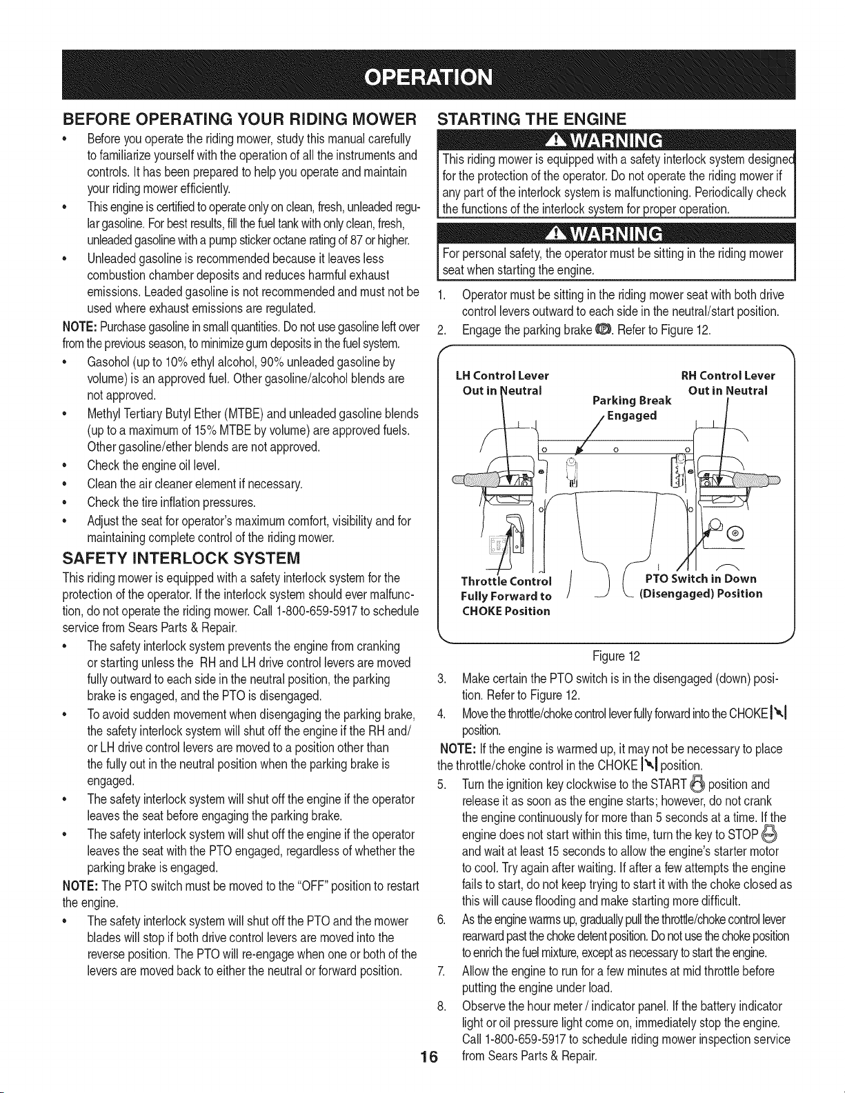
1. Operatormust be sittinginthe ridingmowerseat with bothdrive
controlleversoutwardto each sidein the neutral/startposition.
2. Engagethe parkingbrakeO. Referto Figure12.
LHControlLever RHControlLever
Out in I_eutral Out in Neutral
ParkingBreak
-- Engaged
Throttle Control / ( PTOSwitchin Down
FullyForwardto / __ (Disengaged)Position
CHOKEPosition
Figure12
3. Makecertainthe PTOswitchis in the disengaged(down)posi-
tion. Referto Figure12.
4. Movethethrottle/chokecontrolleverfullyforwardintotheCHOKEt"°,1
position.
NOTE:Ifthe engineiswarmedup,it maynot be necessaryto place
the throttle/chokecontrolin the CHOKE!'_1position.
5. Turnthe ignitionkeyclockwiseto the START_ positionand
releaseit as soonas the enginestarts; however,do not crank
the enginecontinuouslyfor morethan 5 secondsat a time.If the
enginedoes not startwithinthis time,turnthe keyto STOP
andwait at least 15secondsto allowthe engine'sstartermotor
to cool.Tryagainafterwaiting.If after a few attemptsthe engine
failsto start,do not keeptrying to start it withthe chokeclosedas
thiswill causefloodingandmakestartingmoredifficult.
6. Astheenginewarmsup,graduallypullthethrottle/chokecontrollever
rearwardpastthechokedetentposition.Donotusethechokeposition
toenrichthefuelmixture,exceptas necessarytostarttheengine.
7. Allowthe engineto runfor a fewminutesat mid throttlebefore
puttingtheengineunderload.
8. Observethe hour meter/ indicatorpanel.Ifthe batteryindicator
lightoroil pressurelightcomeon, immediatelystopthe engine.
Call1-800-659-5917to scheduleridingmowerinspectionservice
fromSearsParts& Repair.
Cold Weather Starting
Whenstartingtheengineattemperaturesnearorbelowfreezing,
ensurethecorrectviscositymotoroilisusedintheengineandthe
batteryisfullycharged.Starttheengineasfollows:
1. Besurethebatteryisingoodcondition.Also,awarmbatteryhas
muchmorestartingcapacitythanacoldbattery.
2. Usefreshwintergradefuel.Wintergradegasolinehashighervolatility
toimprovestarting.Donotusegasolineleftoverfromsummer.
3. FollowthepreviousinstructionforStartingtheEngine.
Using Jumper CablesTo Start Engine
Batteriescontainsulfuricacidandproduceexplosivegasses.Make
certaintheareaiswellventilated,wearglovesandeyeprotection,
land avod sparksor f amesnear the battery.
Ifthe batterychargeis not sufficientto cranktheengine,rechargethe
battery.Ifa batterychargeris unavailableandthe ridingmowermust
be started,the aidof aboosterbatterywill benecessary.Connectthe
boosterbatteryas follows:
1. Connectthe end of one cableto the disabledridingmowerbat-
tery'spositiveterminal;then connectthe otherendof thatcableto
the boosterbattery'spositiveterminal.
2. Connectone end of the othercableto the boosterbattery's
negativeterminal;then connectthe otherendof thatcableto
the frameof the disabledridingmower,as farfrom the batteryas
possible.
3. Startthe disabledriding mowerfollowingthe normalstarting
instructionspreviouslyprovided;thendisconnectthe jumper
cablesin theexact reverseorderof theirconnection.
4. Havethe ridingmower'selectricalsystemcheckedand repaired
as soonas possibleto eliminatethe needfor jump starting.
STOPPING THE ENGINE
1. Placethe PTOswitchinthe OFF position.
2. Movethe RHand LHdrivecontrolleversfully outwardin the
neutralposition.
3. EngagetheparkingbrakeO.
4. Movethethrottle/chokecontroltomidwaybetweenthe SLOW"_
andFAST_ positions.
5. Turnthe ignitionkeytothe STOP_ positionand removethe key
fromthe ignitionswitch.
NOTE:Alwaysremovethe keyfromthe ignitionswitchto preventacci-
dentalstartingor batterydischargeif the equipmentis left unattended.
PRACTICE OPERATION (INITIAL USE)
Operatinga zero-turnridingmoweris notlikeoperatingaconventional
typeridingridingmower.Becausea zeroturn ridingmoweris more
maneuverable,gettingusedto operatingthecontrolleverstakessome
practice.
Westronglyrecommendthatyoulocatea reasonablylarge,levelandopen
"practicearea"wheretherearenoobstructions,pedestrians,oranimals.You
shouldpracticeoperatingthendingmowerforaminimumof30 minutes.
Carefullymove-- or haveanexperiencedusermove--the ridingmower
to thepracticearea.Whenperformingthe practicesession,the PTO
shouldnotbeengaged.Whilepracticing,operatethe ridingmower
atapproximately1/2to 3/4throttleand at lessthanfull speedin both
forwardandreverse.
Carefullypracticemaneuveringtheridingmowerandproceedto driveas
describedin thefollowingDrivingtheRidingmowerForwardsection.
17
DRIVING THE RIDING MOWER
Avoidsuddenstarts,excessivespeedand suddenstops. ]
1. Adjustthe operator'sseatto the mostcomfortablepositionthat
allowsyou to operatethe controls.See"Adjustingthe Seat" the
Assemblysection.
2. Releasethe parkingbrake_:_.
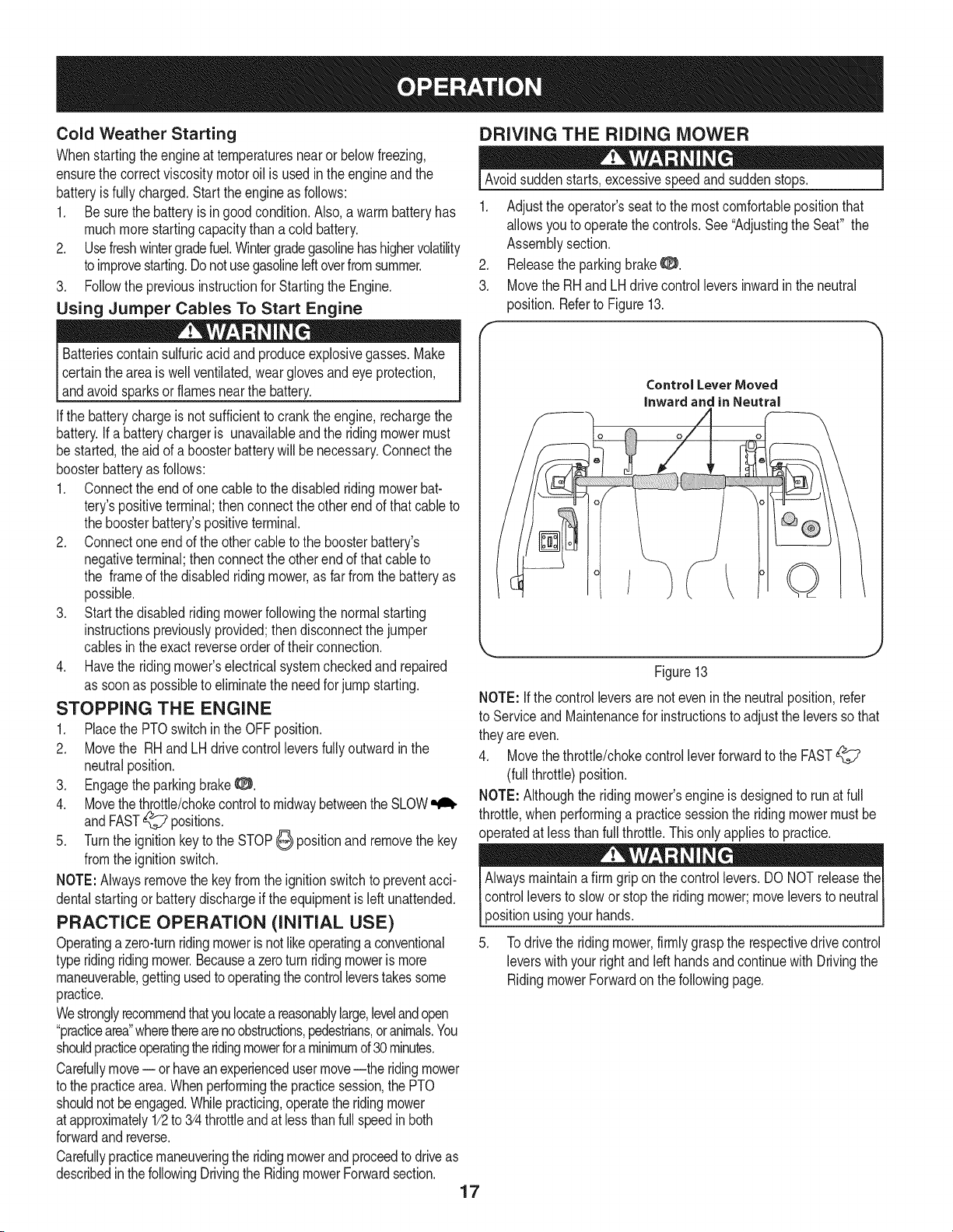
3. Movethe RHand LHdrivecontrol leversinwardin the neutral
position.Referto Figure13.
Control Lever Moved
inward and in Neutral
/
Q
Figure13
NOTE: Ifthe controlleversarenoteven in the neutralposition,refer
to ServiceandMaintenancefor instructionsto adjust the leversso that
theyare even.
4. Movethethrottle/chokecontrolleverforwardto the FAST
(full throttle)position.
NOTE: Althoughthe ridingmower'sengineis designedto runat full
throttle,when performinga practicesessionthe ridingmowermustbe
operatedat lessthan fullthrottle.Thisonly appliesto practice.
Alwaysmaintainafirm griponthe controllevers.DONOTreleasethe
controlleversto slowor stop the ridingmower;move leversto neutral
positionusingyour hands.
5. Todrive the ridingmower,firmlygraspthe respectivedrivecontrol
leverswithyour rightandleft handsandcontinuewith Drivingthe
RidingmowerForwardon the followingpage.
Driving the Riding mower Forward
Keepall movementof the drivecontrolleversslowandsmooth.
Abrupt movementof the controlleverscan affectthe stabilityof the
ridingmowerandcouldcausethe ridingmowerto flip over,which
mayresultin seriousinjury ordeathto the operator.
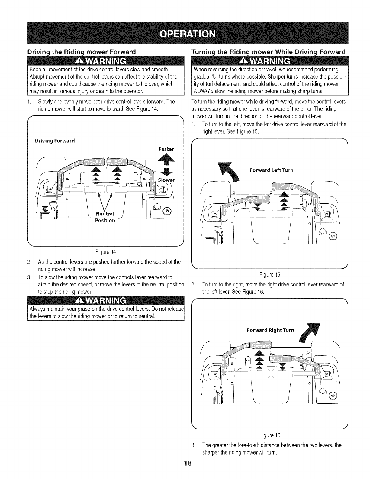
Slowlyandevenlymovebothdrive controlleversforward.The
ridingmowerwill startto moveforward.SeeFigure14.
r
Driving Forward
Faster
Figure14
2. As thecontrolleversare pushedfarther forwardthe speedof the
ridingmowerwill increase.
3. Toslowthe ridingmowermovethe controlslever rearwardto
attainthe desiredspeed,ormovethe leversto the neutralposition
to stopthe ridingmower.
Alwaysmaintainyourgraspon the drivecontrollevers.Donot release
the leversto slowthe ridingmowerorto returnto neutral.
Turning the Riding mower While Driving Forward
Whenreversingthe directionof travel,we recommendperforming
gradual'U' turnswherepossible.Sharperturnsincreasethe possibil-
ity of turfdefacement,and couldaffect controlof the riding mower.
ALWAYSslowthe ridingmowerbeforemakingsharpturns.
Toturn the ridingmowerwhiledrivingforward,movethe controllevers
as necessarysothat oneleveris rearwardd the other.The riding
mowerwill turn inthe directionof the rearwardcontrol lever.
1. Toturn to the left, movethe leftdrivecontrolleverrearwardof the
rightlever.SeeFigure15.
Figure15
2. Toturn to the right,movethe rightdrivecontrollever rearwardof
the left lever.SeeFigure16.
W
ForwardRightTurn F
-oZ-
18
Figure16
3. The greaterthe fore-to-aftdistancebetweenthe twolevers,the
sharperthe ridingmowerwill turn.
4. Toexecutea"zeroturn"movetheturnsidedrivecontrolleverto
theinwardneutralposition,whilemovingtheothercontrollever
forward.
NOTE:Makingazeroturnongrasswillgreatlyincreasethepotential
fordefacementoftheturf.
Driving the Riding mower in Reverse
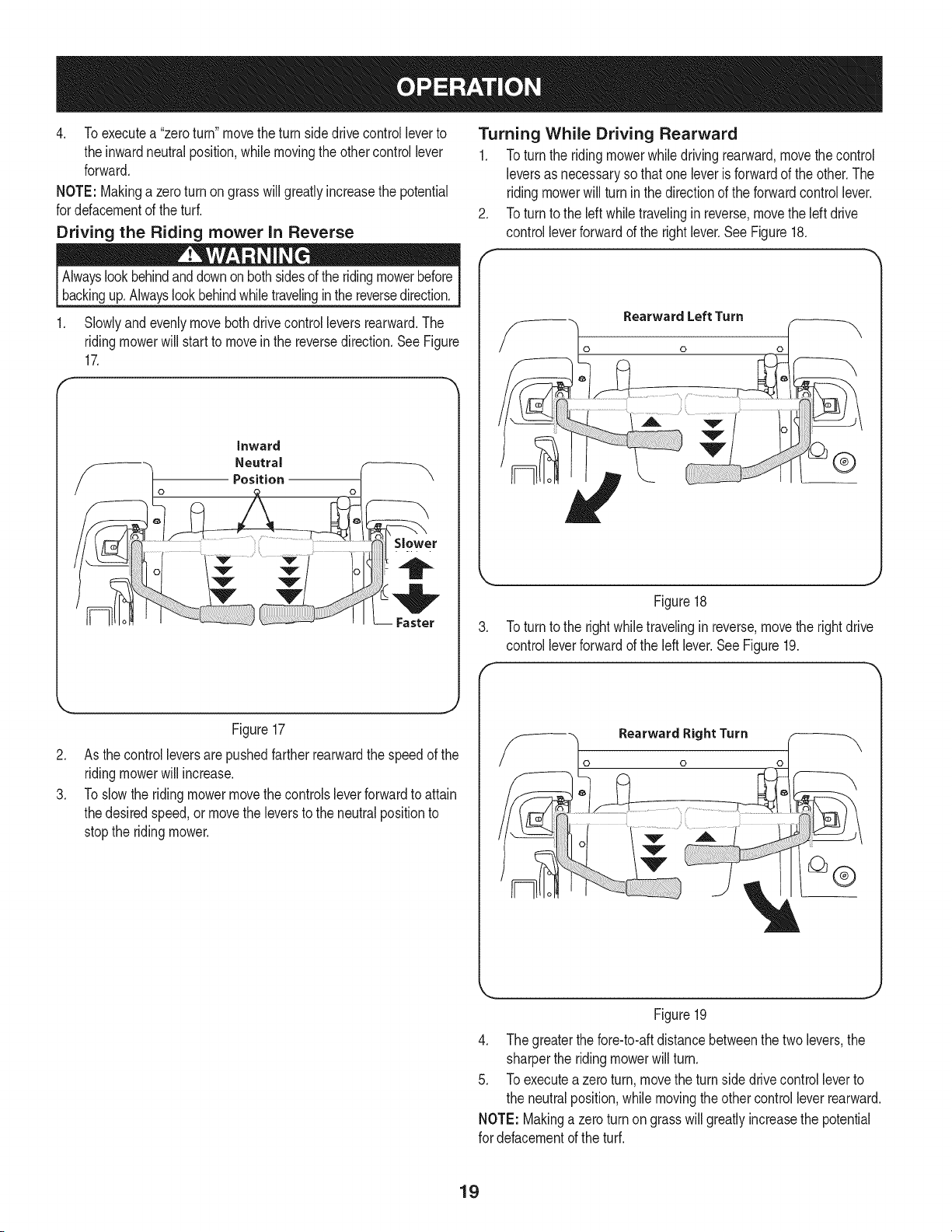
1. Slowlyandevenlymovebothdrivecontrol leversrearward.The
ridingmowerwill start to moveinthe reversedirection.SeeFigure
17.
.
F
Turning While Driving Rearward
1. Toturn the ridingmowerwhiledrivingrearward,movethe control
leversas necessaryso thatone leverisforwardof the other.The
ridingmowerwill turninthedirectionof the forwardcontrollever.
Toturn to the leftwhiletravelinginreverse,movethe left drive
controlleverforwardof the rightlever.See Figure18.
Rearward Left Turn
0
®
.
f
Figure18
Toturn to the rightwhiletravelinginreverse,movethe rightdrive
controlleverforwardof the left lever.SeeFigure19.
.
3.
Figure17
As thecontrolleversarepushedfarther rearwardthe speedof the
ridingmowerwill increase.
Toslowthe ridingmowermovethe controlsleverforwardto attain
thedesiredspeed,or movethe leversto the neutralpositionto
stopthe ridingmower.
Rearward Right Turn
0
Figure19
4. The greaterthe fore-to-aftdistancebetweenthe twolevers,the
sharperthe ridingmowerwillturn.
5. Toexecutea zeroturn, movethe turn sidedrivecontrolleverto
the neutralposition,whilemovingtheother controlleverrearward.
NOTE: Makinga zeroturnon grasswill greatlyincreasethe potential
for defacementofthe turf.
19
Executing a Zero Turn
Whenexecutinga zeroturn,theridingmowerMUSTBESTOPPED.Execut-
ingazeroturnwhiletheridingmoweris movingcansignificantlyreduceyour
controloftheridingmowerandwillcausesevereturfdefacementtooccur.
1. Stopthe forwardor reversemotionof the ridingmowerby moving
the twodrivecontrolleversto neutral.
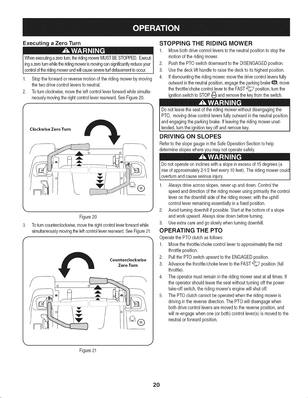
2. Toturnclockwise,movethe leftcontrolleverforwardwhilesimulta-
neouslymovingthe rightcontrolleverrearward.See Figure20.
Clockwise Zero Turn
.
r
Figure20
Toturncounterclockwise,movethe rightcontrolleverforwardwhile
simultaneouslymovingtheleftcontrolleverrearward.SeeFigure21.
Counterclockwise
Zero Turn
STOPPING THE RIDING MOWER
1. Movebothdrivecontrolleversto the neutralpositionto stopthe
motionof the ridingmower.
2. Pushthe PTOswitchdownwardto the DISENGAGEDposition.
3. Usethe deck lift handleto raisethe deck to its highestposition.
4. If dismountingthe ridingmower,movethe drivecontrolleversfully
outwardintheneutralposition,engagethe parkingbrakeO, move
the throttle/chokecontrolleverto the FAST_ position,turnthe
ignitionswitchto STOP_ and removethe keyfromthe switch.
Donot leavethe seatof the ridingmowerwithoutdisengagingthe
PTO, movingdrivecontrolleversfullyoutwardin the neutralposition,
andengagingthe parkingbrake,if leavingthe ridingmowerunat-
tended,turnthe ignitionkeyoff and removekey.
DRIVING ON SLOPES
Referto the slopegaugeinthe SafeOperationSectionto help
determineslopeswhereyou maynot operatesafely.
Donot operateon inclineswitha slopein excessof 15degrees(a
riseof approximately2-1/2feetevery10 feet).The ridingmowercould
overturnandcauseseriousinjury.
1. Alwaysdrive acrossslopes,neverupanddown.Controlthe
speedanddirectionof the riding mowerusing primarilythe control
leveron thedownhillsideof the ridingmower,withthe uphill
controlleverremainingessentiallyina fixedposition.
2. Avoidturningdownhillif possible.Startat the bottomof a slope
andwork upward.Alwaysslowdownbeforeturning.
3. Useextra careand go slowlywhenturningdownhill.
OPERATING THE PTO
Operatethe PTOclutchas follows:
1. Movethe throttle/chokecontrolleverto approximatelythe mid
throttleposition.
2. Pullthe PTOswitchupwardto the ENGAGEDposition.
3. Advancethethrottle/chokeleverto the FAST_? position(full
throttle).
4. The operatormustremaininthe ridingmowerseatat all times.If
the operatorshouldleavethe seatwithoutturningoff the power
take-offswitch,the riding mower'senginewill shutoff.
5. The PTOclutchcannotbeoperatedwhenthe ridingmoweris
drivingin the reversedirection.The PTOwilldisengagewhen
bothdrivecontrolleversaremovedto the reverseposition,and
will re-engagewhenone(or both)controllever(s)is movedto the
neutralorforward position.
Figure21
2O
USING THE MOWER DECK
l Makecertainthe areato be mowedisfree of debris,sticks,stones,
I
wireorother objectsthatcan bethrownby the rotatingblades. ]
NOTE: Donot engagethe mowerdeckwhenloweredingrass.
Prematurewearand possiblefailureof the 'V" beltand PTOclutch
will result.Fullyraisethe deckormovetoa non-grassyarea before
engagingthe mowerdeck.
1. Mowacrossslopes,not upand down. If mowinga slope,startat
bottomandwork upwardto ensureturns are madeuphill.
2. Onthe first passpick a pointon the oppositesideof the areato
be mowed.
3. Engagethe PTOclutchusingthe PTOswitchand movethe
throttle/chokecontrolto the FAST_ position.
4. Lowerthe mowerdeck to the desiredheightsettingusingthe lift
handle.
5. Slowlyandevenlypushthe RH and LH drivecontrollevers
forwardto movethe ridingmowerforward,and keepthe riding
mowerheadeddirectlytowardthe alignmentpoint.
NOTE:The speedof the ridingmowerwill affectthe qualityof the
mowercut. Mowingat full speedwilladverselyaffectthecut quality.
Controlthegroundspeedwith the control levers.
6. Whenapproachingtheotherend of thestrip, slowdownor stop
beforeturning.A U-turnis recommendedunlessa zeroturn is
required.
7. Alignthe mowerwithan edgeof the mowedstripand overlap
approximately3".
8. Directthe ridingmoweroneach subsequentstripto alignwith a
previouslycut strip.
9. Topreventruttingor groovingof theturf, if possible,changethe
directionthatthe stripsare mowedby approximately450for the
nextand eachsubsequentmowing.
Becarefulwhencrossinggravelpathsor driveways.Disengagethe
PTOandraisethe deckto the highestpositionbeforecrossing.
l
NOTE:Whenstoppingthe ridingmowerfor any reasonwhileona
grasssurface,always:
• Placethecontrolleversinneutral,
• Engagethe parkingbrake8,
• Shutengineoff and removethe key.
• Doingso will minimizethe possibilityof havingyourlawn
"browned"by hotexhaustfromyourridingmower'srunning
engine.
CHECKING SAFETY iNTERLOCK CiRCUiTS
Periodicallycheckthe safetyinterlockcircuitsto ensuretheyare
workingproperly.If a safetycircuitis notworkingas designed,call
1-800-659-5917to scheduleridingmowerinspectionservicefrom
Sears Parts& Repair.DO NOToperatethe ridingmowerif any safety
circuitis notfunctioningproperly.Tocheckthe safetycircuits,proceed
as follows:
1. Sittingin the ridingmowerseatwith bothdrivecontrollevers
openedfullyoutward,DISENGAGEthe parkingbrake0 and
momentarilyturn the ignitionswitchto the START_ position.
The engineshouldnotcrank.
2. Engagethe parkingbrake0 and pull the PTOswitchupwardto
the ENGAGEDposition.Momentarilyturn the ignitionswitchto
the START_ position;the engineshouldnotcrank.
3. Pushthe PTOswitchdownwardto the DISENGAGEDposition
and ENGAGEthe parkingbrake0. Startthe engineand move
oneof the drivecontrolleversfromthe fullyoutwardneutral
position.Theengineshouldstoprunning.Repeatthe procedure
withthe oppositecontrollever.
4. Movebothcontrolleversfully outwardin the neutralpositionand
DISENGAGEthe parkingbrake0; then liftupwardfromthe
operator'sseat.The engineshouldstop.
5. Withbothcontrol leversfully outwardin the neutralpositionand
the parkingbrakeENGAGED0, ENGAGEthe PTO.Liftupward
fromthe operator'sseat;the engineshouldstop.
6. Startthe ridingmower,DISENGAGEthe parkingbrake0, and
movethecontrol leversinwardto the neutraloperatingposition.
ENGAGEthe PTOand movebothcontrolleverslowlyintothe
slowreverseposition;the PTOshoulddisengageand the mower
deckshouldstop untilone or bothof the controlleversis moved
to the neutralorforwardposition.
21
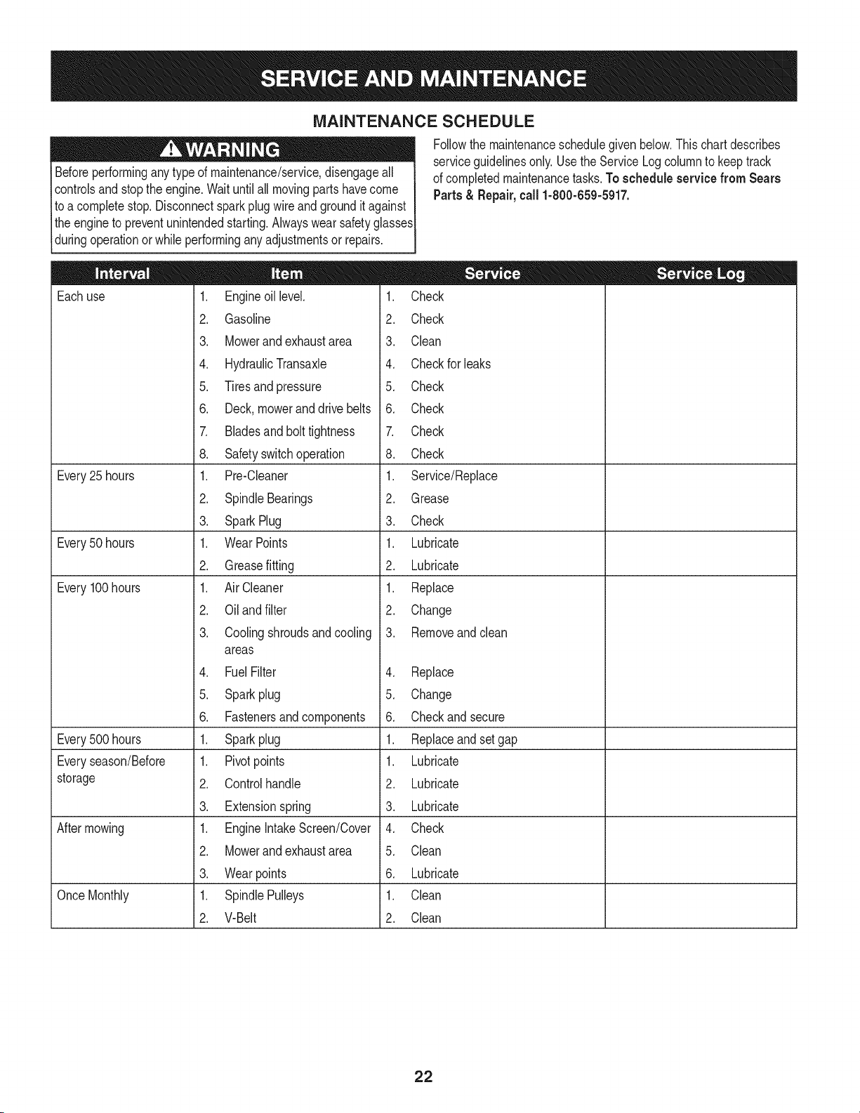
MAINTENANCE SCHEDULE
Beforeperforminganytypeof maintenance/service,disengageall
controlsandstop the engine.Wait untilall movingpartshavecome
to acompletestop. Disconnectsparkplugwireand groundit against
theengineto preventunintendedstarting.Alwayswearsafetyglasses
duringoperationorwhile performingany adjustmentsor repairs.
Eachuse
Every25 hours
Every50 hours
Every100hours
Every500 hours
Everyseason/Before
storage
Aftermowing
Once Monthly
1. Engineoillevel.
2. Gasoline
3. Mowerand exhaustarea
4. HydraulicTransaxle
5. Tiresand pressure
6. Deck,moweranddrivebelts
7. Bladesand bolttightness
8. Safetyswitchoperation
1. Pre-Cleaner
2. SpindleBearings
3. SparkPlug
1. WearPoints
2. Greasefitting
1. AirCleaner
2. Oiland filter
3. Coolingshroudsand cooling
areas
4. FuelFilter
5. Sparkplug
6. Fastenersand components
1. Sparkplug
1. Pivotpoints
2. Controlhandle
3. Extensionspring
1. EngineIntakeScreen/Cover
2. Mowerand exhaustarea
3. Wearpoints
1. SpindlePulleys
2. V-Belt
Followthe maintenanceschedulegivenbelow.Thischartdescribes
serviceguidelinesonly.Use theService Log columnto keeptrack
of completedmaintenancetasks.To schedule service from Sears
Parts& Repair,call 1-800-659-5917.
1. Check
2. Check
3. Clean
4. Checkfor leaks
5. Check
6. Check
7. Check
8. Check
1. Service/Replace
2. Grease
3. Check
1. Lubricate
2. Lubricate
1. Replace
2. Change
3. Removeand clean
4. Replace
5. Change
6. Checkandsecure
1. Replaceandsetgap
1. Lubricate
2. Lubricate
3. Lubricate
4. Check
5. Clean
6. Lubricate
1. Clean
2. Clean
22
Beforeperformingany maintenanceor repairs,disengagethe PTO,
movethe drivecontrolleversfullyoutwardin the neutralposition,
engagethe parkingbrake,stoptheengineand removethe key to
preventunintendedstarting.
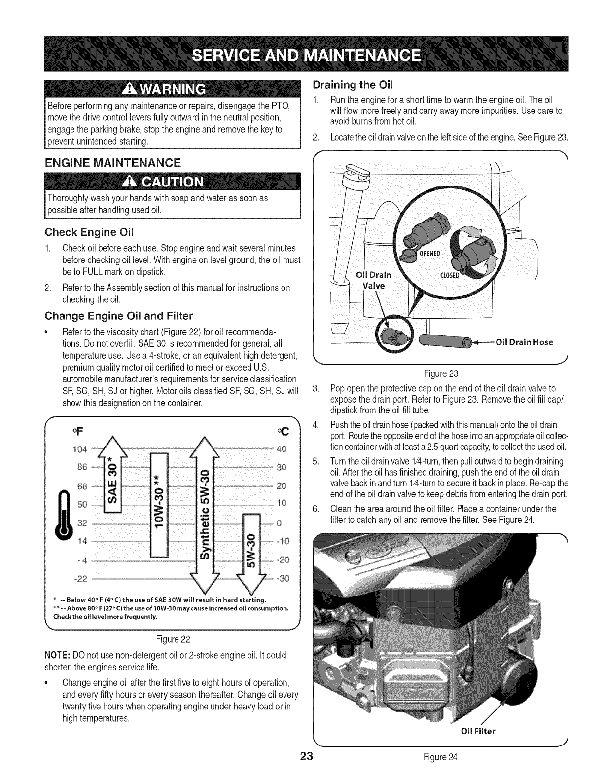
Draining the Oil
1. Runthe enginefor a shorttimeto warmthe engineoil. The oil
will flowmorefreelyandcarryawaymoreimpurities.Usecare to
avoidburnsfromhotoil.
2. Locatetheoil drainvalveontheleftsideof theengine.SeeFigure23.
ENGINE MAINTENANCE
Thoroughlywashyourhandswithsoapand wateras soon as
possibleafterhandlingusedoil.
Check Engine Oil
1. Checkoilbeforeeachuse.Stopengineandwait severalminutes
beforecheckingoil level.Withengineon levelground,the oil must
beto FULLmarkon dipstick.
2. Referto the Assemblysectionof thismanualfor instructionson
checkingthe oil.
Change Engine Oil and Filter
• Referto the viscositychart(Figure22) foroil recommenda-
tions.Do notoverfill.SAE30 is recommendedfor general,all
temperatureuse. Usea 4-stroke,or anequivalenthighdetergent,
premiumqualitymotoroilcertifiedto meetor exceedU.S.
automobilemanufacturer'srequirementsfor serviceclassification
SF,SG,SH,SJ or higher.Motoroils classifiedSF,SG,SH,SJ will
showthisdesignationon thecontainer.
a6 .
50
_4
°22
4O
iU L:F ¸3o
i...................................................................20
C
C
>
0
10
_20
-30
-- Below 40 ° F (4 ° C) the use of SAE 30W will result in hard starting.
** -- Above 80 ° F (27 ° C) the use of 10W-30 may cause increased oil consumption,
Check the oil level more frequently,
Figure22
NOTE: DOnot usenon-detergentoil or2-strokeengineoil. it could
shortenthe enginesservicelife.
o Changeengineoil afterthe first five to eighthoursof operation,
andeveryfifty hoursor every seasonthereafter.Changeoil every
twentyfivehourswhenoperatingengineunder heavyload or in
hightemperatures.
Figure23
3. Popopen the protectivecapon theend of the oil drain valveto
exposethe drainport. Referto Figure23. Removethe oil fill cap/
dipstickfromthe oil fill tube.
4. Pushtheoil drainhose(packedwiththismanual)ontotheoildrain
port.Routetheoppositeendd thehoseintoanappropriateoilcollec-
tioncontainerwithat leasta 2.5quartcapacity,to collectthe usedoil.
5. Turnthe oildrainvalve1/4-turn,thenpulloutwardto begindraining
oil. Aftertheoil hasfinisheddraining,pushtheendof theoildrain
valvebackin andturn 1/4-turnto secureitbackin place.Re-capthe
endof theoil drainvalveto keepdebrisfromenteringthedrain port.
6. Cleanthe areaaround theoil filter.Placea containerunderthe
filterto catchany oiland removethefilter.See Figure24.
23 Figure24
7. Placethe newfilterin an open panwith the open sidefacing up.
Fillwith newoil untilthe oil reachedthe bottomof the threads.
Waittwo minutesforthe oil to beabsorbedby the filtermaterial.
8. Applya thinfilm of cleanoil to the rubbergasketonthe filter.
9. Carefullyinstallthe newfilter.
10. Refillthe enginewith the recommendedoil and checkthe oil
level;referto CheckingandAddingOil in theAssemblySection.
Reinstallthe oilfiller cap/dipsticksecurely.
Reconnectsparkplugwire.
11.
12.
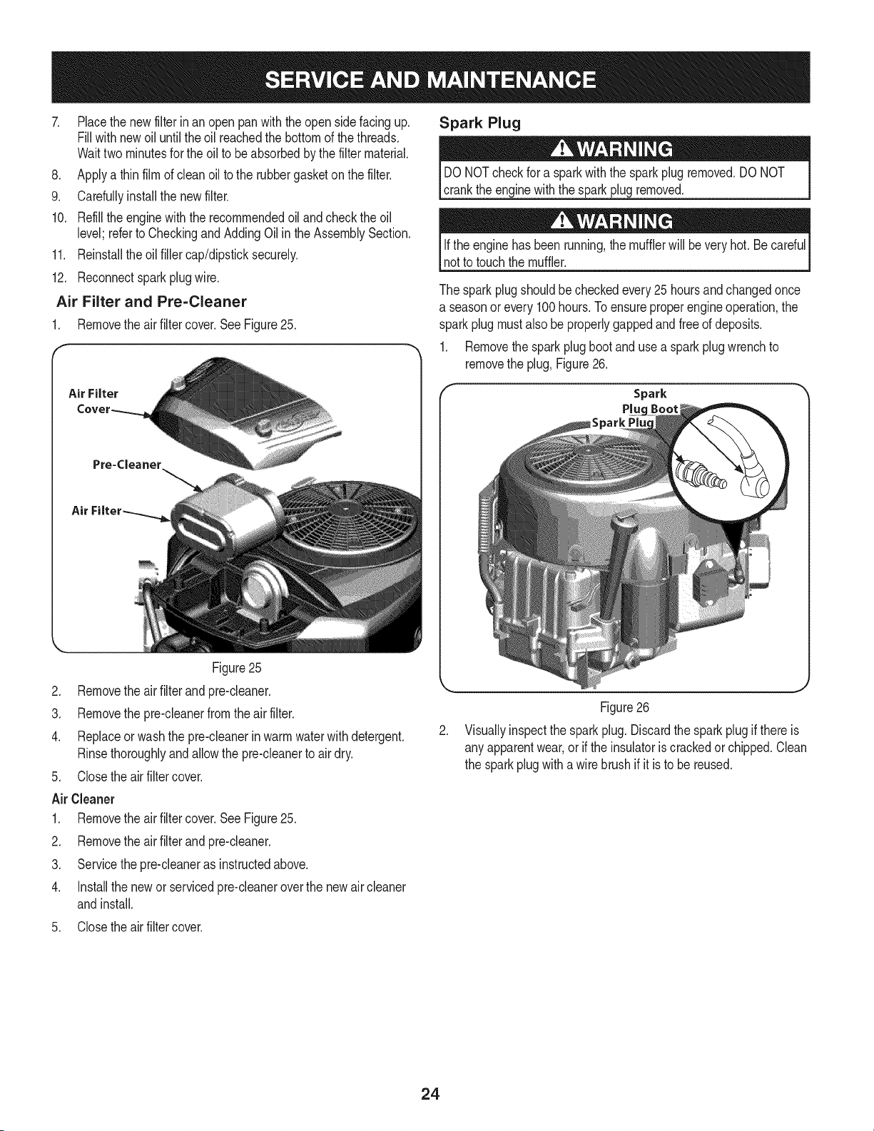
Air Filter and Pre=Cleaner
1. Removethe air filtercover.See Figure25.
Figure25
Air Filter
Pre=Cleaner
Air
Spark Plug
DONOTcheckfor a sparkwiththe sparkplugremoved.DONOT
crankthe enginewiththe sparkplug removed.
Ifthe enginehas beenrunning,the mufflerwill beveryhot. Be cardul
notto touchthe muffler.
The sparkplugshouldbecheckedevery 25 hoursand changedonce
a seasonor every 100hours.Toensureproperengineoperation,the
sparkplug mustalsobe properlygappedand freeof deposits.
1. Removethe spark plugboot and usea spark plugwrenchto
removethe plug,Figure26.
Spark
Pluc
2. Removethe air filterand pre-cleaner.
3. Removethe pre-cleanerfromthe air filter.
4. Replaceor washthe pre-cleanerinwarmwaterwithdetergent.
Rinsethoroughlyandallowthe pre-cleanerto air dry.
5. Closethe airfilter cover.
Air Cleaner
1. Removethe air filtercover.See Figure25.
2. Removethe air filterand pre-cleaner.
3. Servicethe pre-cleaneras instructedabove.
4. Installthe newor servicedpre-cleaneroverthe newair cleaner
andinstall.
5. Closethe airfilter cover.
Figure26
2. Visuallyinspectthe sparkplug. Discardthe sparkplug if thereis
any apparentwear,or if the insulatoris crackedor chipped.Clean
the sparkplugwitha wire brushif it is to be reused.
24
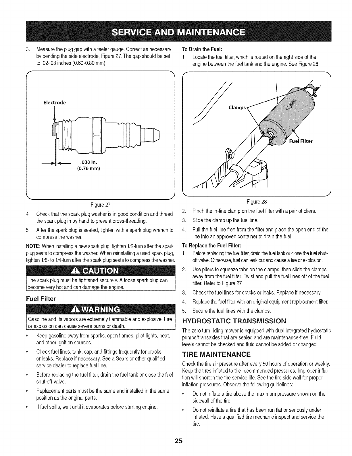
3. Measurethe pluggapwitha feelergauge.Correctas necessary To Drain the Fuel:
by bendingthe side electrode,Figure27.Thegapshouldbe set 1. Locatethe fuel filter,whichis routedonthe right sideof the
to .02-.03inches(0.60-0.80ram). enginebetweenthe fueltankandthe engine.See Figure28.
Electrode
.030 in.
(0.76 ram)
Clamps_
Figure27
4. Checkthatthe sparkplugwasheris in good conditionand thread
the sparkplugin by handto preventcross-threading.
5. Afterthespark plug is seated,tightenwith a spark plugwrenchto
compressthe washer.
NOTE:Wheninstallinga newsparkplug,tighten1/2-turnafterthe spark
plugseatstocompressthewasher.Whenreinstallinga usedsparkplug,
tighten1/8-to 1/4-turnafterthe sparkplugseatsto compressthewasher.
The sparkplugmustbetightenedsecurely.A loosesparkplug can
becomevery hotandcan damagethe engine.
Fuel Filter
Gasolineandits vaporsare extremelyflammableandexplosive.Fire
or explosioncan causesevereburnsor death.
• Keepgasolineawayfrom sparks,open flames,pilotlights,heat,
andotherignitionsources.
• Checkfuellines,tank,cap, and fittingsfrequentlyfor cracks
orleaks.Replaceif necessary.Seea Searsor other qualified
servicedealerto replacefuel line.
• Beforereplacingthe fuel filter,drain the fueltank or closethe fuel
shut-offvalve.
• Replacementpartsmustbe the same and installedin the same
positionas the originalparts.
• If fuelspills,wait until it evaporatesbeforestartingengine.
Figure28
2. Pinchthe in-line clampon the fuel filter with a pairof pliers.
3. Slidethe clampup thefuel line.
4. Pullthe fuel line freefrom the filter and placethe open end of the
lineintoanapprovedcontainerto drainthe fuel.
To Replacethe Fuel Filter:
1. Beforereplacingthefuelfilter,drainthefueltankor closethefuelshut-
offvalve.Otherwise,fuelcanleakoutandcausea fireor explosion.
2. Usepliersto squeezetabson the clamps,thenslidethe clamps
awayfromthe fuelfilter.Twistandpullthe fuel linesoffof thefuel
filter.Referto Figure27.
3. Checkthe fuel linesforcracks or leaks.Replaceif necessary.
4. Replacethefuel filterwithan originalequipmentreplacementfilter.
5. Securethe fuellineswith the clamps.
HYDROSTATIC TRANSMISSION
The zeroturn ridingmoweris equippedwithdualintegratedhydrostatic
pumps/transaxlesthatare sealedand are maintenance-free.Fluid
levelscannotbecheckedandfluidcannotbe added or changed.
TIRE MAINTENANCE
Checkthe tire airpressureafterevery50 hoursof operationorweekly.
Keepthetires inflatedto the recommendedpressures.Improperinfla-
tion will shortenthe tireservicelife.Seethe tire sidewallfor proper
inflationpressures.Observethe followingguidelines:
• Donot inflatea tire abovethe maximumpressureshownon the
sidewallof the tire.
• Donot reinflatea tire thathas been runflat or seriouslyunder
inflated.Haveaqualifiedtire mechanicinspectand servicethe
tire.
25
LUBRiCATiON
Usinga pressurelubricatinggun, lubricatethe frontcastorwheel
axlesandthe front pivot axlewith No.2 multipurposelithium
greaseafterevery 10 hoursof service.
Periodicallylubricateall otherpivotpointswitha qualitylubricat-
ingoil.
GENERAL BATTERY iNFORMATiON
Shouldbatteryacidaccidentallysplatterinto theeyesor ontothe
skin, rinsethe affectedareaimmediatelywithcleancold water.If
thereis any furtherdiscomfort,seekpromptmedicalattention.If acid
spillsonclothing,first diluteit withcleanwater,then neutralizewitha
solutionof ammonia/wateror bakingsoda/water.
NEVERconnect(ordisconnect)batterychargerclipstothebatterywhile
thechargeris turnedon,asitcancausesparks.Keepallsourcesofignition
(cigarettes,matches,lighters)awayfromthebattery.Thegasgenerated
duringchargingcanbecombustible.Asafurtherprecaution,onlycharge
thebatteryina wellventilatedarea.Alwaysshieldeyesandprotectskin
_andcothngwhenworkngnearbatteres.
Batteriescontainsulfuricacidandmayemitexplosivegases.Useextreme
cautionwhenhandlingbatteries.Keepbatteriesoutofthereachofchildren.
Battery Maintenance
The batteryis filled withbatteryacid andthensealedat the factory.
However,evena "maintenancefree" batteryrequiressomemainte-
nanceto ensureits properlife cycle.
Spraytheterminalsandexposedwire witha batteryterminalsealer,
orcoatthe terminalswith a thincoat of greaseor petroleumjelly,to
protectagainstcorrosion.
Alwayskeepthe batterycablesandterminalscleanand freeof
corrosion.
Avoidtipping.Evena sealedbatterywill leak electrolytewhentipped.
BATTERY REMOVAL
leadcompounds.Washhandsafterhandling.
The batteryis locatedonthe right/rearof the ridingmowerbeneaththe
seatbox frame.To removethe battery:
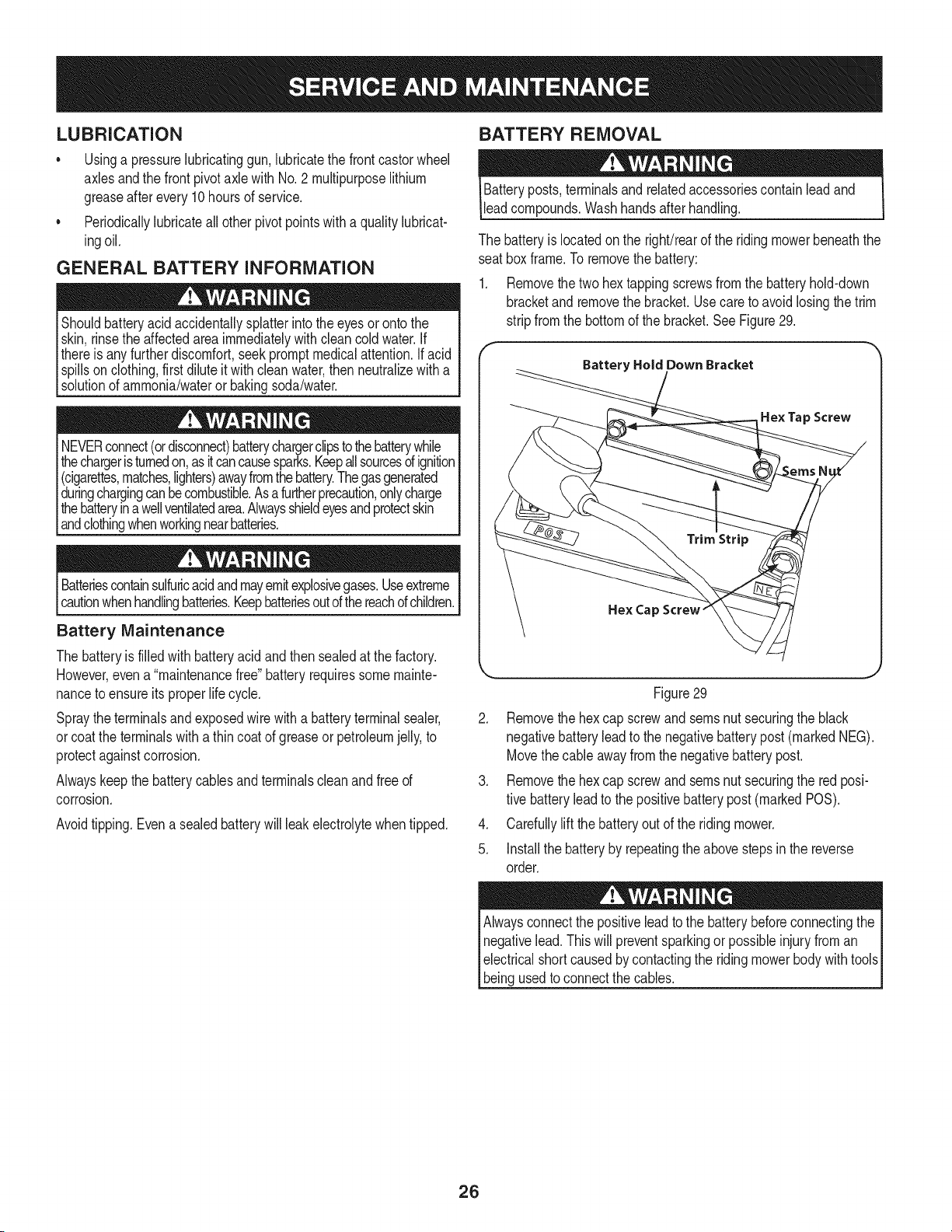
1. Removethe two hextappingscrewsfrom thebatteryhold-down
bracketand removethe bracket.Usecareto avoidlosingthe trim
stripfromthe bottomof thebracket.SeeFigure29.
f
Battery Hold Down Bracket
Hex Tap Screw
Hex Cap Screw"
Figure29
2. Removethe hexcap screwand seresnut securingthe black
negativebatteryleadto the negativebatterypost (markedMEG).
Movethecable awayfromthe negativebatterypost.
3. Removethe hexcap screwand seresnut securingthe red posi-
tive batteryleadto the positivebatterypost (markedPOS).
4. Carefullylift the batteryout of the ridingmower.
5. Installthe batteryby repeatingthe abovestepsin the reverse
order.
Alwaysconnectthe positiveleadto the batterybeforeconnectingthe
negativelead.Thiswill preventsparkingor possibleinjuryfrom an
electricalshortcausedbycontactingthe ridingmowerbodywithtoolsI
I bengusedto connectthe cab es. j
26
Charging the Battery
1. Testand,if necessary,rechargethebatteryafter the riding
mowerhasbeenstoredfor a periodof time.
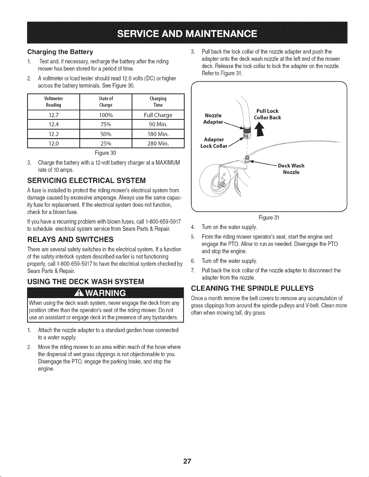
2. A voltmeterorloadtestershouldread 12.6volts(DC) or higher
acrossthebatteryterminals.SeeFigure30.
Voltmeter Stateof Charging
Reading Charge Time
12.7 100% Full Charge
12.4 75% 90 Min.
12.2 50% 180 Min.
12.0 25% 280 Min.
Figure30
3. Chargethe batterywith a 12-voltbatterychargerat a MAXIMUM
rateof 10amps.
SERViCiNG ELECTRICAL SYSTEM
A fuseisinstalledto protectthe ridingmower'selectricalsystemfrom
damagecausedby excessiveamperage.Alwaysusethe samecapac-
ityfusefor replacement.Ifthe electricalsystemdoes notfunction,
checkfor a blownfuse.
If youhavea recurringproblemwithblownfuses,call 1-800-659-5917
to schedule electricalsystemservicefromSearsParts& Repair.
RELAYS AND SWITCHES
Thereareseveralsafetyswitchesinthe electricalsystem.Ifa function
of the safetyinterlocksystemdescribedearlieris not functioning
properly,call 1-800-659-5917to havetheelectricalsystemcheckedby
SearsParts& Repair.
USING THE DECK WASH SYSTEM
Whenusingthe deckwashsystem,neverengagethe deckfrom any
positionotherthanthe operator'sseatof the ridingmower.Do not
usean assistantorengagedeck in the presenceof any bystanders.
Pullbackthe lock collarof the nozzleadapterandpushthe
adapterontothedeckwash nozzleat the left end of the mower
deck. Releasethe lockcollarto lockthe adapteron the nozzle.
Referto Figure31.
Deck Wash
Nozzle
Figure31
4. Turnonthe watersupply.
5. Fromthe ridingmoweroperator'sseat,startthe engineand
engagethe PTO.Allowto runas needed.Disengagethe PTO
and stopthe engine.
6. Turnoffthe water supply.
7. Pullbackthe lock collarof the nozzleadapterto disconnectthe
adapterfromthe nozzle.
CLEANING THE SPINDLE PULLEYS
Oncea monthremovethe beltcoversto removeany accumulationof
grassclippingsfromaroundthe spindlepulleysandV-belt.Cleanmore
oftenwhenmowingtall, dry grass.
,
Attachthe nozzleadapterto a standardgardenhoseconnected
to a watersupply.
Movethe ridingmowerto an areawithinreachof the hosewhere
the dispersalof wetgrassclippingsis notobjectionableto you.
Disengagethe PTO,engagethe parkingbrake,andstopthe
engine.
27
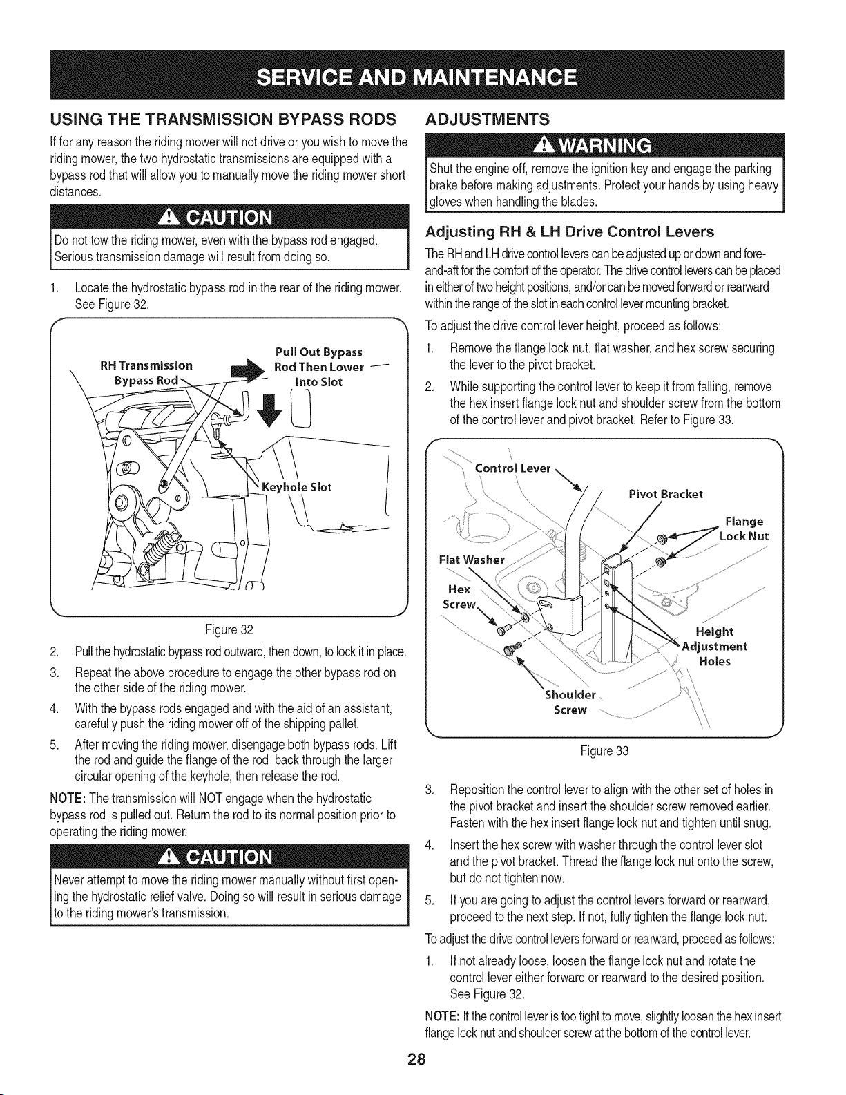
USING THE TRANSMiSSiON BYPASS RODS
Iffor any reasonthe ridingmowerwillnot driveor youwishto movethe
ridingmower,the twohydrostatictransmissionsareequippedwitha
bypassrodthatwill allowyou to manuallymovethe ridingmowershort
distances.
Do nottowthe ridingmower,evenwiththe bypassrodengaged.
Serioustransmissiondamagewill resultfromdoingso.
1. Locatethe hydrostaticbypassrod in the rear of the ridingmower.
SeeFigure32.
RH Transmission
Bypass
PullOut Bypass
RodThenLower
into Slot
Keyhole Slot
Figure32
2. Pullthehydrostaticbypassrodoutward,thendown,to lockitinplace.
3. Repeattheaboveproceduretoengagethe otherbypassrod on
theother sideof the ridingmower.
4. Withthe bypassrodsengagedand with the aid of an assistant,
carefullypushthe ridingmoweroff of the shippingpallet.
5. Aftermovingthe ridingmower,disengageboth bypassrods. Lift
the rodandguidethe flangeof the rod backthroughthe larger
circularopeningof the keyhole,then releasethe rod.
NOTE:The transmissionwill NOTengagewhenthe hydrostatic
bypassrodispulledout. Returnthe rodto itsnormalpositionpriorto
operatingthe ridingmower.
Neverattemptto movethe ridingmowermanuallywithoutfirstopen-
ling the hydrostaticr,elief valve.Doingso will resultin seriousdamage
[to the ridingmowers transmission.
ADJUSTMENTS
Shuttheengineoff, removethe ignitionkeyand engagethe parking
brakebeforemakingadjustments.Protectyourhandsby usingheavyI
lg oveswhen hand ng the b ades. j
Adjusting RH & LH Drive Control Levers
TheRHandLHdrivecontrolleverscanbeadjustedupordownandfore-
and-aftforthecomfortoftheoperator.Thedrivecontrolleverscanbeplaced
ineitheroftwoheightpositions,and/orcanbe movedforwardorrearward
withintherangeoftheslotineachcontrollevermountingbracket.
Toadjustthedrive controlleverheight,proceedas follows:
1. Removethe flangelock nut, flat washer,and hexscrewsecuring
the leverto the pivotbracket.
2. Whilesupportingthecontrolleverto keepitfromfalling, remove
the hex insertflangelocknut andshoulderscrewfromthe bottom
of the controlleverandpivot bracket.Referto Figure33.
f
\
Fiat Washer
Hex
Shoulder
Screw
PivotBracket 1
%2:°' J
Figure33
3. Repositionthe controlleverto alignwith theother set of holesin
the pivotbracketand insertthe shoulderscrewremovedearlier.
Fastenwiththe hexinsertflangelock nutandtighten untilsnug.
4. Insertthe hex screwwith washerthroughthe control leverslot
andthe pivot bracket.Threadtheflange locknutontothe screw,
but do nottightennow.
5. If you are goingto adjust thecontrol leversforwardor rearward,
proceedtothe nextstep.If not, fully tightenthe flangelock nut.
Toadjustthedrivecontrolleversforwardor rearward,proceedasfollows:
1. Ifnot alreadyloose, loosenthe flangelock nut and rotatethe
controllevereitherforwardor rearwardto thedesiredposition.
See Figure32.
NOTE:Ifthecontrolleveristootightto move,slightlyloosenthehexinsert
flangelocknutandshoulderscrewatthebottomof thecontrollever.
28
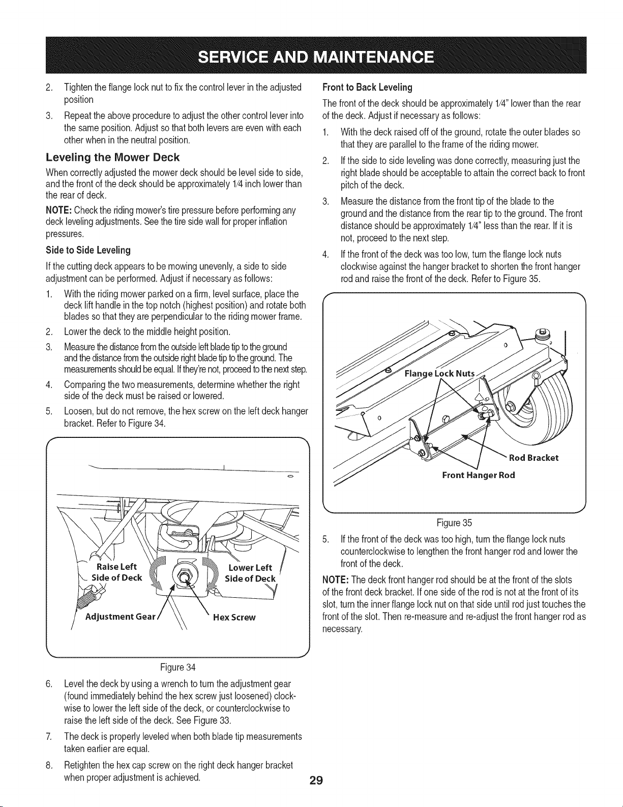
2. Tightentheflange locknutto fix thecontrol leverin the adjusted
position
3. Repeattheaboveprocedureto adjustthe othercontrolleverinto
the sameposition.Adjustsothat bothleversare evenwith each
otherwheninthe neutralposition.
Leveling the Mower Deck
Whencorrectlyadjustedthe mowerdeck shouldbelevel sideto side,
andthe frontof the deck shouldbe approximately1/4inchlowerthan
the rearof deck.
NOTE:Checkthe ridingmower'stirepressurebeforeperformingany
decklevelingadjustments.See thetire sidewallfor properinflation
pressures.
Side to Side Leveling
If thecuttingdeckappearsto be mowingunevenly,a sideto side
adjustmentcan be performed.Adjustif necessaryas follows:
.
.
3.
.
Withthe ridingmowerparkedon a firm,levelsurface,placethe
decklift handlein the top notch (highestposition)androtateboth
bladessothatthey are perpendicularto the ridingmowerframe.
Lowerthe deckto the middleheightposition.
MeasurethedistancefromtheoutsideIdt bladetiptotheground
andthedistancefromtheoutsiderightbladetipto theground.The
measurementsshouldbe equal.Ifthey'renot,proceedtothenextstep.
Comparingthetwo measurements,determinewhetherthe right
sideof the deckmust beraisedorlowered.
5. Loosen,butdo not remove,the hexscrewon the left deck hanger
bracket.Referto Figure34.
f
J
<=,
Front to Back Leveling
The frontof thedeck shouldbeapproximately1/4"lowerthan the rear
of the deck.Adjustifnecessaryas follows:
1. Withthe deckraisedoffof the ground,rotatetheouterbladesso
thatthey are parallelto the frameof the ridingmower.
2. If the sideto sidelevelingwas done correctly,measuringjust the
rightbladeshouldbeacceptableto attainthe correctback to front
pitchof the deck.
3. Measurethedistancefromthe front tip of the bladeto the
groundandthe distancefrom the rear tip to the ground.Thefront
distanceshouldbe approximately1/4"lessthanthe rear.If it is
not,proceedto the next step.
4. If the front of thedeck was too low,turn the flangelock nuts
clockwiseagainstthe hangerbracketto shortenthe fronthanger
rodand raisethe frontof the deck. Referto Figure35.
Bracket
Front Hanger Rod
Figure35
Ifthe frontof thedeckwas too high,turn theflangelock nuts
counterclockwiseto lengthenthe fronthangerrod and lowerthe
frontof the deck.
NOTE:Thedeckfronthangerrod shouldbe at the front of the slots
of the frontdeckbracket.If one side of the rod is not at the frontof its
slot,turnthe innerflange locknuton thatside untilrodjust touchesthe
frontof the slot.Then re-measureand re-adjustthefronthangerrodas
necessary.
J
Figure34
6. Levelthe deck by usinga wrenchto turnthe adjustmentgear
(foundimmediatelybehindthe hex screwjustloosened)clock-
wiseto lowertheleft sideof the deck,or counterclockwiseto
raisethe leftside of the deck.SeeFigure33.
7. Thedeckis properlyleveledwhenbothblade tip measurements
takenearlierareequal.
8. Retightenthe hex capscrewon the rightdeck hangerbracket
whenproperadjustmentis achieved.
29
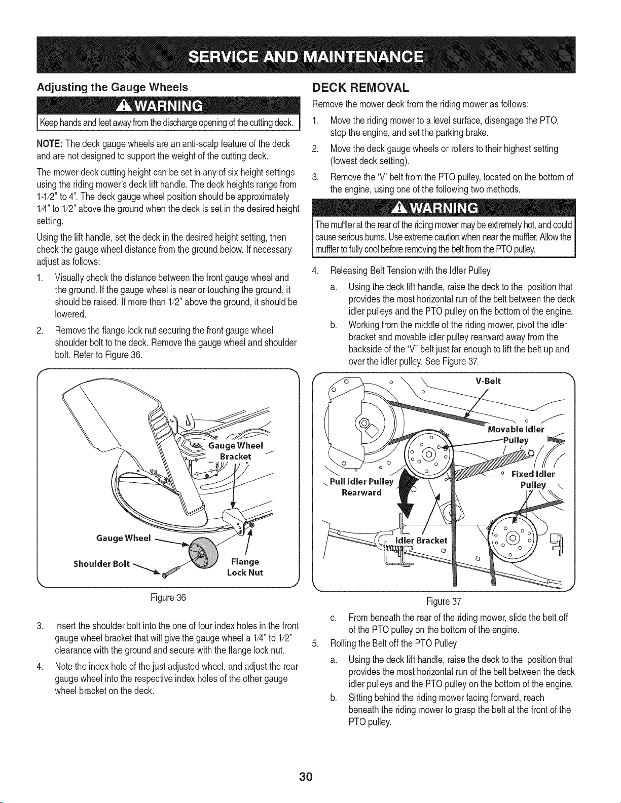
Adjusting the Gauge Wheels
Keephandsandfeetawayfromthedischargeopeningd thecuttingdeck.
NOTE:The deckgaugewheelsarean anti-scalpfeatureof the deck
andare not designedto supportthe weightof the cuttingdeck.
The mowerdeckcuttingheightcan besetinanyof six heightsettings
usingthe ridingmower'sdecklift handle.Thedeckheightsrangefrom
1-1/2"to 4".The deckgaugewheelpositionshouldbe approximately
1/4"to 1/2"abovethegroundwhenthe deckisset inthe desiredheight
setting.
Usingthe lift handle,setthe deck inthe desiredheightsetting,then
checkthegaugewheeldistancefrom theground below.If necessary
adjustas follows:
1. Visuallycheckthe distancebetweenthe frontgaugewheeland
theground.If thegaugewheelisnear or touchingthe ground,it
shouldberaised. If morethan 1/2"abovethe ground,itshouldbe
lowered.
.
Removethe flangelocknut securingthefrontgaugewheel
shoulderboltto thedeck. Removethe gaugewheelandshoulder
bolt.Referto Figure36.
Gauge Wheel
Bracket
Gauge Wheel
Shoulder Bolt
Flange
Lock Nut
Figure36
3. Insertthe shoulderbolt intothe oneof fourindexholesin the front
gaugewheelbracketthatwill givethe gaugewheela 1/4"to 1/2"
clearancewiththe groundandsecurewiththe flangelocknut.
4. Notethe indexholeof the justadjustedwheel,andadjustthe rear
gaugewheelintothe respectiveindexholesof the othergauge
wheelbracketonthe deck.
DECK REMOVAL
Removethe mowerdeckfromthe ridingmoweras follows:
1. Movethe ridingmowerto a levelsurface,disengagethe PTO,
stopthe engine,and set the parkingbrake.
2. Movethedeck gaugewheelsor rollersto their highestsetting
(lowestdecksetting).
3. Removethe 'V' beltfrom the PTOpulley,locatedonthe bottomof
the engine,usingoneof the followingtwo methods.
Themufflerattherearoftheridingmowermaybeextremelyhot,andcould
causeseriousbums.Useextremecautionwhennearthemuffler.Allowthe I
I muffertofu y coo beforeremovngthebetfromthePTOpu ey. j
.
ReleasingBeltTensionwiththe Idler Pulley
a. Usingthedeck lift handle,raisethedeck to the positionthat
providesthe mosthorizontalrunof the belt betweenthe deck
idlerpulleysandthe PTOpulleyonthe bottomof theengine.
b. Workingfromthe middleof the ridingmower,pivot the idler
bracketand movableidlerpulleyrearwardawayfromthe
backsideof the 'V" beltjustfar enoughto lift the belt up and
overthe idlerpulley.SeeFigure37.
V=Belt
.
Figure37
c. Frombeneaththe rearof the ridingmower,slidethe beltoff
of the PTOpulleyonthe bottomof the engine.
Rollingthe Beltoff the PTOPulley
a. Usingthedeck lift handle,raisethedeck to the positionthat
providesthe mosthorizontalrunof the belt betweenthe deck
idlerpulleysandthe PTOpulleyonthe bottomof theengine.
b. Sittingbehindthe ridingmowerfacingforward,reach
beneaththe ridingmowerto graspthe beltat the frontof the
PTOpulley.
30
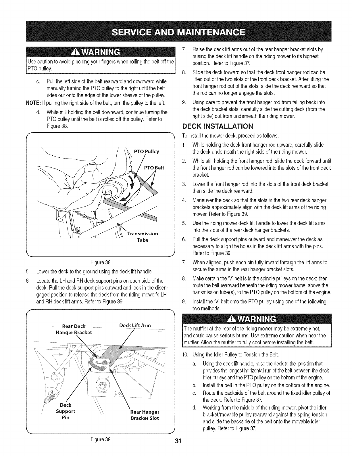
Usecautionto avoidpinchingyourfingerswhen rollingthe belt offthe
PTOpulley.
c. Pullthe leftsideof the beltrearwardanddownwardwhile
manuallyturningthe PTOpulleyto the right untilthe belt
ridesout ontothe edgeof the lowersheaveof the pulley.
NOTE: Ifpullingthe right sideof the belt,turnthe pulleyto the left.
d. Whilestillholdingthe beltdownward,continueturningthe
PTOpulleyuntilthe belt is rolledoff the pulley.Referto
Figure38.
f
PTO Belt
\
.
6.
f
Transmission
Tube
,,J
Figure38
Lowerthe deckto the groundusingthe decklift handle.
Locatethe LHand RHdeck supportpinson each sideof the
deck.Pullthe decksupportpinsoutwardand lock in the disen-
gagedpositionto releasethe deck from the ridingmower'sLH
andRH deck lift arms.Referto Figure39.
-- Rear Deck Deck Lift Arm
Hanger Bracket
i
Deck
Support _\ Rear Hanger
Pin Bracket Slot
Figure39
7. Raisethe decklift arms outof the rearhangerbracketslotsby
raisingthe decklift handleon the ridingmowerto its highest
position.Referto Figure37.
8. Slidethe deck forwardsothat the deck front hangerrodcan be
liftedout of the twoslotsof the frontdeckbracket.Afterliftingthe
fronthangerrod out of the slots, slidethedeck rearwardsothat
the rodcan no longerengagethe slots.
9. Usingcareto preventthe front hangerrod from fallingback into
the deckbracketslots, carefullyslidethe cuttingdeck(fromthe
rightside)out fromunderneaththe ridingmower.
DECK INSTALLATION
To installthe mowerdeck, proceedas follows:
1. Whileholdingthe deckfronthangerrodupward,carefullyslide
the deckunderneaththe rightside of the ridingmower.
2. Whilestill holdingthefront hanger rod,slidethe deck forwarduntil
the fronthangerrod can be loweredinto the slotsof the frontdeck
bracket.
3. Lowerthefront hanger rod intothe slotsof the front deck bracket,
then slidethe deckrearward.
4. Maneuverthe deck so that the slotsin the two reardeck hanger
bracketsapproximatelyalignwith the deck lift arms of the riding
mower.Referto Figure39.
5. Usethe ridingmowerdeck lift handleto lowerthe deck lift arms
intothe slotsof the reardeckhangerbrackets.
6. Pullthe deck supportpins outwardand maneuverthe deck as
necessaryto alignthe holesin the deckliftarmswiththe pins.
Referto Figure39.
7. Whenaligned,pusheachpinfullyinwardthroughthe liftarmsto
securethe armsinthe rearhangerbracketslots.
8. Makecertainthe'V' beltis inthespindlepulleysonthe deck;then
routethebelt rearwardbeneaththeridingmowerframe,abovethe
transmissiontube(s),to the PTOpulleyonthe bottomof theengine.
9. Installthe 'V' beltonto the PTOpulleyusingoneof the following
two methods.
The mufflerat the rearof the ridingmowermaybe extremelyhot,
andcouldcause seriousburns.Use extremecautionwhennear the
[muffer. A ow the mufferto fu y coo before nsta ngthe bet.
10.
Usingthe IdlerPulleyto Tensionthe Belt.
a. Usingthedeck lifthandle,raisethedecktothe positionthat
providesthelongesthorizontalrund thebeltbetweenthedeck
idlerpulleysandthe PTOpulleyonthebottomof theengine.
b. Installthe belt inthe PTOpulleyonthe bottomof theengine.
c. Routethebacksideof the belt aroundthefixedidlerpulleyof
the deck. Referto Figure37.
d. Workingfromthe middleof the ridingmower,pivot the idler
bracket/movablepulleyrearwardagainstthe springtension
and slidethe backsideofthe beltontothe movableidler
pulley.Referto Figure37.
31
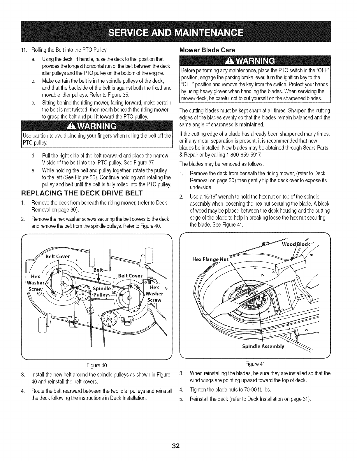
11.
Rollingthe Beltintothe PTOPulley.
a. Usingthedecklifthandle,raisethedecktothe positionthat
providesthe longesthorizontalrunof thebeltbetweenthedeck
idlerpulleysandthe PTOpulleyonthe bottomoftheengine.
b. Makecertainthe beltis in the spindlepulleysof the deck,
andthat the backsideof the beltis againstboth thefixedand
movableidlerpulleys.Referto Figure35.
c. Sittingbehindthe ridingmower,facing forward,makecertain
the belt is nottwisted;then reachbeneaththe ridingmower
to graspthe beltand pullit towardthe PTOpulley.
Usecautionto avoidpinchingyourfingerswhenrollingthe belt off the
PTOpulley.
d. Pullthe rightside ofthe beltrearwardand placethe narrow
V sideof the belt intothe PTOpulley.See Figure37.
e. Whileholdingthe beltandpulleytogether,rotatethepulley
to the left(SeeFigure36). Continueholdingand rotatingthe
pulleyandbeltuntil the beltis fully rolledintothe PTOpulley.
REPLACING THE DECK DRIVE BELT
1. Removethe deck from beneaththe riding mower,(referto Deck
Removalon page30).
2. Removethehexwasherscrewssecuringthebeltcoverstothedeck
andremovethebeltfromthespindlepulleys.Referto Figure40.
Hex
Washer_
Screw
Hex
Washer
Screw
Figure40
3. Installthe newbeltaroundthe spindlepulleysas shownin Figure
40and reinstallthe belt covers.
.
Routethe belt rearwardbetweenthe twoidlerpulleysandreinstall
thedeckfollowingthe instructionsin DeckInstallation.
Mower Blade Care
Beforeperforminganymaintenance,placethe PTOswitchin the"OFF"
position,engagetheparkingbrakelever,turntheignitionkeyto the
"OFF"positionand removethe keyfrom theswitch.Protectyourhands
byusingheavygloveswhenhandlingthe blades.Whenservicingthe
mowerdeck,becarefulnotto cutyourselfonthe sharpenedblades.
The cuttingbladesmustbekeptsharpat all times. Sharpenthe cutting
edgesof the bladesevenlyso thatthe bladesremainbalancedandthe
sameangleof sharpnessis maintained.
Ifthe cuttingedgeof a bladehas alreadybeen sharpenedmanytimes,
or if any metalseparationis present,it is recommendedthatnew
bladesbe installed.Newbladesmaybe obtainedthroughSears Parts
& Repairor by calling 1-800-659-5917.
The bladesmaybe removedas follows.
1. Removethe deck from beneaththe ridingmower,(referto Deck
Removalon page30) thengentlyflip the deck overto exposeits
underside.
.
Usea 15/16"wrenchto holdthe hexnut ontop of the spindle
assemblywhenlooseningthe hex nutsecuringthe blade.A block
of wood maybe placedbetweenthe deckhousingandthecutting
edgeof the bladeto help in breakingloosethe hex nutsecuring
the blade.SeeFigure41.
//
WoodBlock/
He× Flang,
Spindle Assembly
Figure41
3. When reinstallingthe blades,besurethey are installedso thatthe
wind wingsarepointingupwardtowardthe top of deck.
4. Tightenthe bladenutsto 70-90ft. Ibs.
5. Reinstallthe deck (referto DeckInstallationon page 31).
32
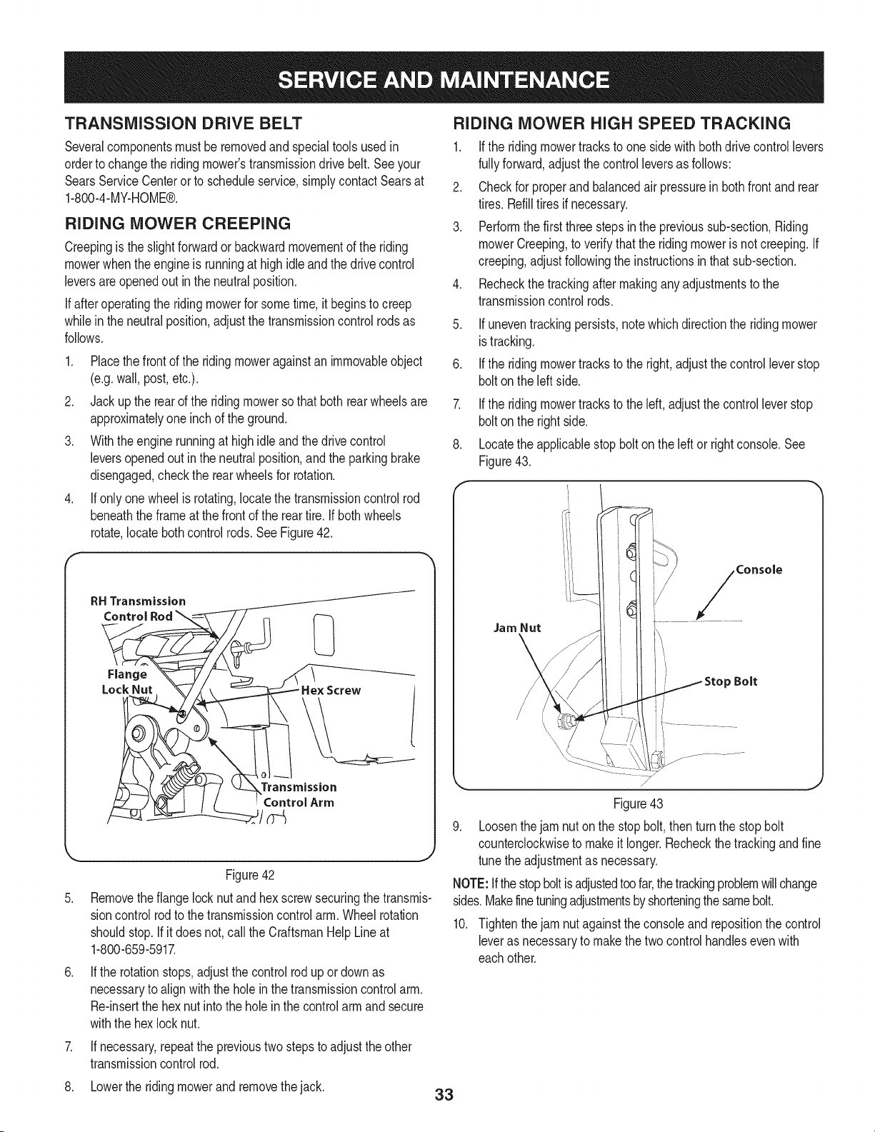
TRANSMiSSiON DRIVE BELT
Severalcomponentsmust beremovedandspecialtoolsusedin
orderto changethe ridingmower'stransmissiondrivebelt.Seeyour
SearsServiceCenterorto scheduleservice,simplycontactSearsat
1-800-4-MY-HOME®.
RIDING MOWER CREEPING
Creepingis the slightforwardor backwardmovementof the riding
mowerwhentheengineis runningat highidle and the drivecontrol
leversareopenedout in the neutralposition.
If afteroperatingthe ridingmowerfor sometime,it beginsto creep
whilein the neutralposition,adjustthe transmissioncontrolrodsas
follows.
1. Placethefrontof the ridingmoweragainstan immovableobject
(e.g.wall,post,etc.).
2. Jackup the rearof the ridingmowersothat bothrear wheelsare
approximatelyoneinch of the ground.
3. Withtheengine runningat high idle and thedrive control
leversopenedout inthe neutralposition,and the parkingbrake
disengaged,checkthe rearwheelsfor rotation.
4. If onlyone wheelis rotating,locatethetransmissioncontrol rod
beneaththe frameat the frontof the reartire. Ifbothwheels
rotate,locatebothcontrolrods. See Figure42.
RH Transmission
Flange
Lock Nut
J
Transmission
Arm
Figure42
5. Removetheflangelock nut and hex screwsecuringthe transmis-
sioncontrolrod to thetransmissioncontrolarm.Wheelrotation
shouldstop.Ifit doesnot, call the CraftsmanHelp Lineat
1-800-659-5917.
.
7.
If the rotationstops,adjustthe controlrodup or downas
necessaryto alignwiththe holeinthe transmissioncontrolarm.
Re-insertthe hexnut intothe holein the controlarmandsecure
withthe hexlocknut.
If necessary,repeatthe previoustwostepsto adjustthe other
transmissioncontrolrod.
RIDING MOWER HIGH SPEED TRACKING
1. Ifthe riding mowertracksto onesidewith bothdrivecontrollevers
fullyforward,adjustthecontrol leversas follows:
2. Checkfor properand balancedair pressurein bothfrontand rear
tires. Refilltiresif necessary.
3. Performthe firstthree stepsin the previoussub-section,Riding
mowerCreeping,to verifythat the ridingmoweris not creeping.If
creeping,adjustfollowingthe instructionsinthatsub-section.
4. Recheckthe trackingafter makinganyadjustmentsto the
transmissioncontrolrods.
5. If uneventrackingpersists,notewhichdirectionthe riding mower
istracking.
6. If the riding mowertracks to the right,adjust thecontrol leverstop
boltonthe left side.
7. Ifthe ridingmowertracksto the left,adjustthecontrolleverstop
boltonthe rightside.
8. Locatethe applicablestop bolton the left or rightconsole.See
Figure43.
Jam Nut
Console
Bolt
Figure43
9. Loosenthejam nut on the stop bolt, thenturn the stopbolt
counterclockwiseto makeit longer.Recheckthe trackingandfine
tune theadjustmentas necessary.
NOTE:Ifthestopboltisadjustedtoofar,thetrackingproblemwillchange
sides.Makefinetuningadjustmentsbyshorteningthesamebolt.
10. Tightenthejam nutagainstthe consoleandrepositionthe control
leveras necessaryto makethetwo controlhandlesevenwith
eachother.
8. Lowerthe ridingmowerand removethejack. 33
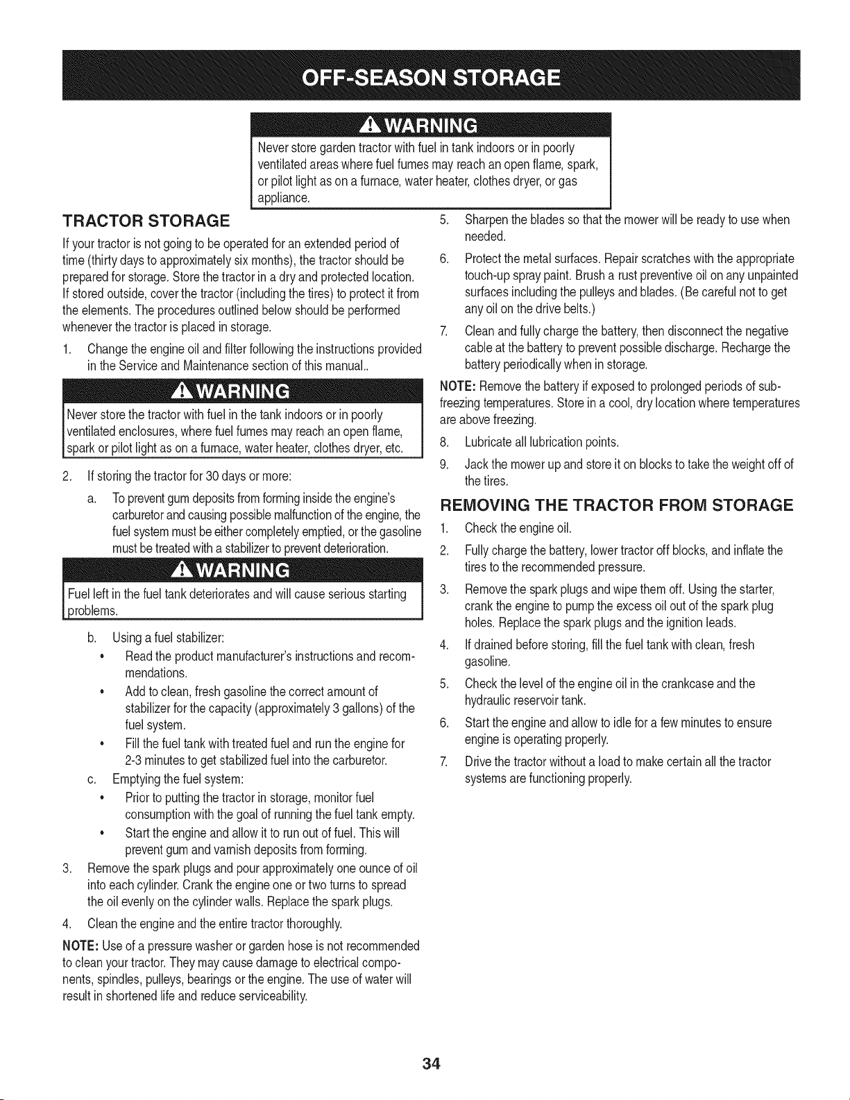
TRACTOR STORAGE
If yourtractoris notgoingto be operatedfor an extendedperiodof
time(thirtydaysto approximatelysix months),the tractorshouldbe
preparedfor storage.Storethetractorin a dry andprotectedlocation.
If storedoutside,coverthe tractor(includingthe tires)to protectit from
the elements.Theproceduresoutlinedbelowshouldbeperformed
wheneverthetractoris placedin storage.
1. Changethe engineoil and filterfollowingthe instructionsprovided
in theServiceand Maintenancesectionof this manual..
Neverstorethe tractorwithfuel inthe tankindoorsor in poorly
ventilatedenclosures,wherefuelfumesmayreachan openflame,
sparkor pilotlight as ona furnace,waterheater,clothesdryer,etc.
.
Neverstoregardentractorwithfuel in tank indoorsor in poorly
ventilatedareaswherefuel fumesmayreachan openflame,spark,
or pilot lightas ona furnace,waterheater,clothesdryer,or gas
appliance.
5. Sharpenthe bladesso that the mowerwill be readyto use when
needed.
If storingthetractorfor 30days or more:
a. Topreventgumdepositsfromforminginsidetheengine's
carburetorandcausingpossiblemalfunctionof the engine,the
fuelsystemmustbeeithercompletelyemptied,orthe gasoline
mustbetreatedwitha stabilizerto preventdeterioration.
9roblems.
b. Usingafuel stabilizer:
• Readthe productmanufacturer'sinstructionsand recom-
mendations.
• Addto clean,fresh gasolinethe correctamountof
stabilizerforthe capacity(approximately3 gallons)of the
fuel system.
• Fillthe fuel tankwith treatedfueland runthe engine for
2-3minutesto get stabilizedfuel intothe carburetor.
c. Emptyingthefuel system:
• Priorto puttingthe tractorinstorage,monitorfuel
consumptionwiththe goalof runningthefuel tankempty.
• Startthe engineand allowit to runout of fuel. This will
preventgum andvarnishdepositsfromforming.
3. Removethespark plugsand pour approximatelyoneounceof oil
intoeachcylinder.Crankthe engineoneor two turns to spread
the oilevenlyonthe cylinderwalls.Replacethe sparkplugs.
4. Cleantheengineand theentiretractorthoroughly.
NOTE: Useof a pressurewasheror gardenhoseis not recommended
to cleanyourtractor.Theymaycausedamageto electricalcompo-
nents,spindles,pulleys,bearingsorthe engine.The useof waterwill
resultin shortenedlife andreduceserviceability.
6. Protectthe metalsurfaces.Repairscratcheswith the appropriate
touch-upspraypaint.Brusha rust preventiveoil on any unpainted
surfacesincludingthe pulleysandblades.(Becarefulnot to get
any oilon thedrive belts.)
7. Cleanand fully chargethe battery,thendisconnectthe negative
cableat thebatteryto preventpossibledischarge.Rechargethe
batteryperiodicallywhenin storage.
NOTE:Removethebatteryif exposedto prolongedperiodsof sub-
freezingtemperatures.Storeina cool, dry locationwheretemperatures
areabovefreezing.
8. Lubricateall lubricationpoints.
9. Jack the mowerup andstoreit onblocksto takethe weightoff of
the tires.
REMOVING THE TRACTOR FROM STORAGE
1. Checkthe engineoil.
2. Fullychargethe battery,lowertractoroff blocks,and inflatethe
tiresto the recommendedpressure.
3. Removethe sparkplugsand wipe themoff. Usingthe starter,
crankthe engineto pumpthe excessoil out of the sparkplug
holes.Replacethe sparkplugsandthe ignitionleads.
4. If drainedbeforestoring,fill the fueltank with clean,fresh
gasoline.
5. Checkthe levelof the engineoil in the crankcaseand the
hydraulicreservoirtank.
6. Startthe engineand allowto idlefor a few minutesto ensure
engineis operatingproperly.
7. Drivethe tractorwithouta loadto makecertainall thetractor
systemsarefunctioningproperly.
34
Beforeperforminganytypeof maintenance/service,disengageall
controlsandstoptheengine.Waituntilallmovingpartshavecometo
acompletestop.Disconnectsparkplugwireandgrounditagainstthe
I engineto preventunintendedstarting.Alwayswearsafetyglassesduring
l operationorwhileperforminganyadjustmentsor repairs.
Thissectionaddressesminor service issues.To scheduleserviceat a SearsParts& RepairCenter,callthe CraftsmanHelp Lineat
1. PTO/BladeEngageknobengaged.
2. Parkingbrakenotengaged.
3. Sparkplugwire disconnected.
1-800-858-5817.
Enginefailsto start
Enginerunserratically
4. Throttlecontrollevernot incorrect starting
position.
5. Fueltank empty,or stalefuel.
6. Blockedfuel lineorfuel filter.
1. Placeknobindisengaged(OFF)position.
2. Engageparkingbrake.
3. Connectwireto sparkplug.
7. Faultysparkplug.
8. Engineflooded.
9. Fuse(s)blown.
4. PlaceThrottleleverto FASTposition.
5. Filltankwith clean,fresh (less than 30 days old) gas.
6. Replacefuel line.Seea Searsorotherqualified
servicedealer.Replacefuelfilter. Seethe Service
1. TractorrunningwithChokeactivated.
2. Sparkplugwire loose.
3. Blockedfuel lineor stalefuel.
4. Ventin gas cap plugged.
5. Wateror dirt in fuel system.
6. Dirtyair cleaner.
andMaintenancesection.
7. Clean,adjustgapor replaceplug.
8. Crankenginewiththrottlein FASTposition.
9. Replacefuse.
1. Checkthatthe electricchokeis working.Seea
Searsorotherqualifiedservicedealer.
2. Connectandtighten spark plugwire.
3. Replacefuel line.Seea Searsorotherqualified
servicedealer.Filltankwithclean,freshgasoline
andreplacefuelfilter. Seethe Serviceand Mainte-
nancesection.
4. Clearventor replacecap if damaged.
5. Drainfuel tank. Refillwithclean,fresh gasoline.See
the Serviceand Maintenancesection.
6. Cleanor replaceair cleanerpaper elementor clean
foampre-cleaner.
• lili
NEED MORE HELP?
Find this and a[[ your other product manuals online.
Get answers from our team of home experts.
Get a personalized maintenance plan for your home.
Find information and toots to hetp with home projects.
b es_t _e yon by Sea_s
35
Engineoverheats 1. Engineoillevellow
2. Air flowrestricted
.
2.
Enginehesitatesat highRPMs 1. Sparkpluggap settoo close 1.
Engineidles poorly 1. Fouledspark plug 1.
2. Dirtyair cleaner 2.
Excessivevibration 1. Cuttingbladeslooseor unbalanced 1.
2. Damaged,dull,or bentcuttingblade 2.
Unevencut 1. Decknot leveledproperly. 1.
2. Dullblade. 2.
3. Uneventire pressure. 3.
Fillenginewith properamountandtype of oil.
Cleangrassclippingsanddebrisfrom aroundthe
engine'scoolingfinsandblowerhousing.
Removesparkplugand adjustgap.
Replacesparkplugand adjustgap.
Cleanor replaceair cleanerelementand/orclean
pre-cbaner.
Tightenbladeand spindle.Balanceblade.
Replaceblade.
Performside-to-sidedeckadjustment.
Sharpenor replaceblade.
Checktire pressureinallfour tires.
....... L
NEED MORE HELP?
Find this and a[[ your other product manuals online,
Get answers from our team of home experts.
Get a persona[ized maintenance plan for your home.
Find information and tools to help with home projects,
@ managemylife
bI'_u_htte yes b_4Sea_
_ (((((((((((((((((((((((((((S ((((((((((((((((((((((((
36
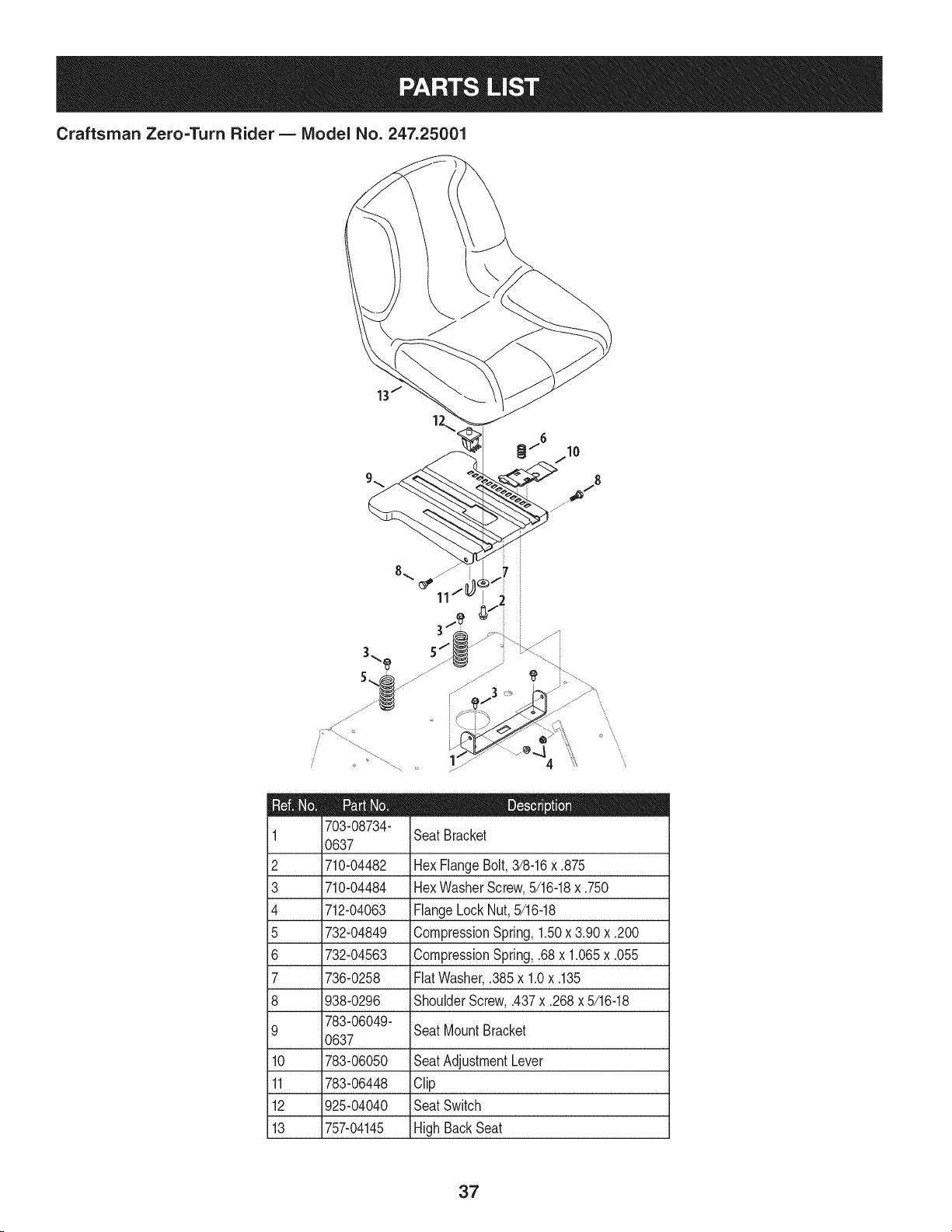
Craftsman Zero=Turn Rider B IViodel No. 247.25001
11
5 /
I = _ O
703-08734-
1 SeatBracket
0637
2 710-04482 HexFlangeBolt,3/8-16x ,875
3 710-04484 HexWasherScrew,5/16-18x ,750
4 712-04063 FlangeLockNut,5/16-18
5 732-04849 CompressionSpring,1,50x 3,90 x ,200
6 732-04563 CompressionSpring,,68x 1,065x .055
7 736-0258 FlatWasher,,385x 1,0x ,135
8 938-0296 ShoulderScrew,,437x .268x 5/16-18
783-06049-
9 SeatMountBracket
0637
10 783-06050 SeatAdjustmentLever
11 783-06448 Clip
12 925-04040 SeatSwitch
13 757-04145 HighBackSeat
37
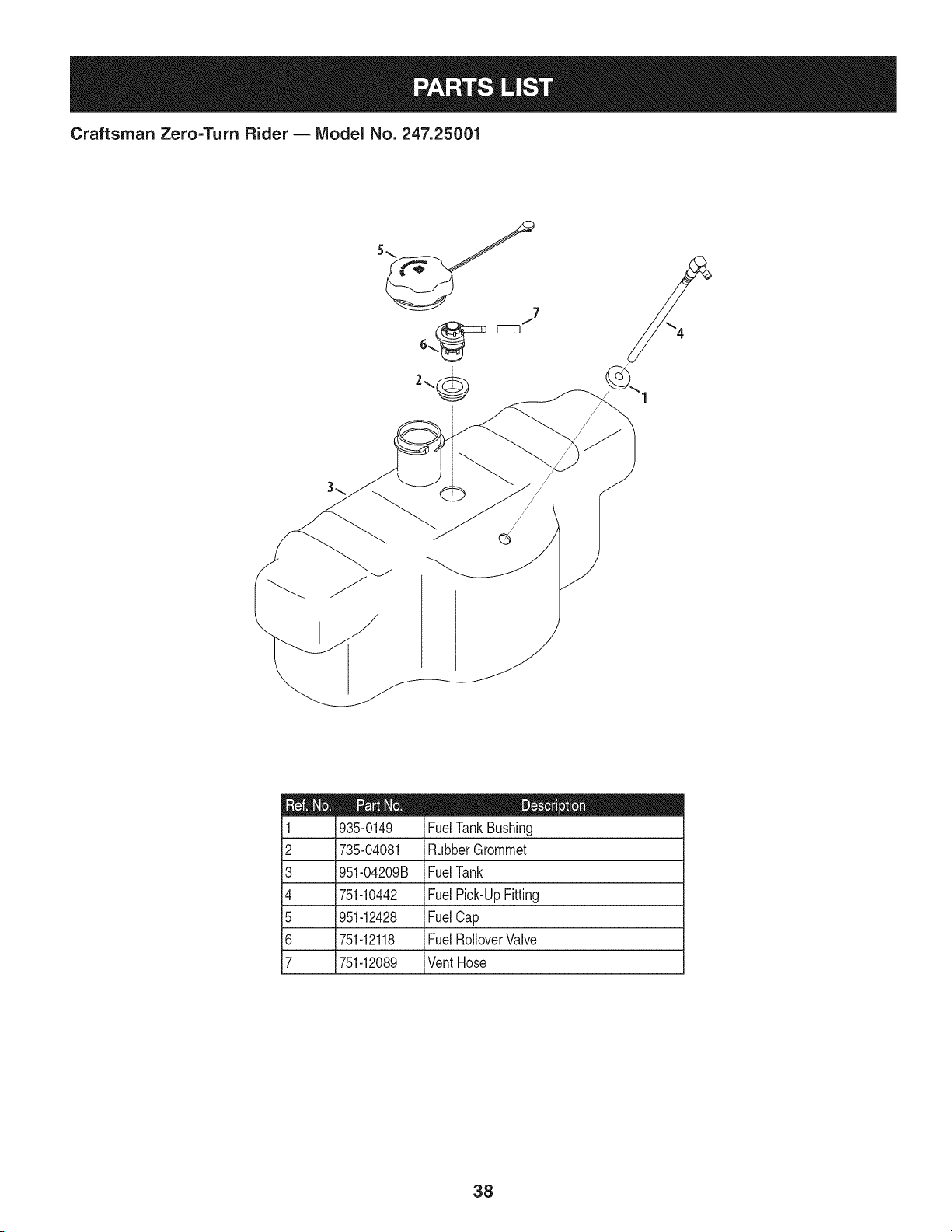
Craftsman Zero=Turn Rider B Model No. 247.25001
2
3
4
5
6
7
935-0149
735-04081
951-04209B
751-10442
951-12428
751-12118
751-12089
FuelTankBushing
iRubberGrommet
FuelTank
FuelPick-UpFitting
iFuelCap
FuelRolloverValve
VentHose
38
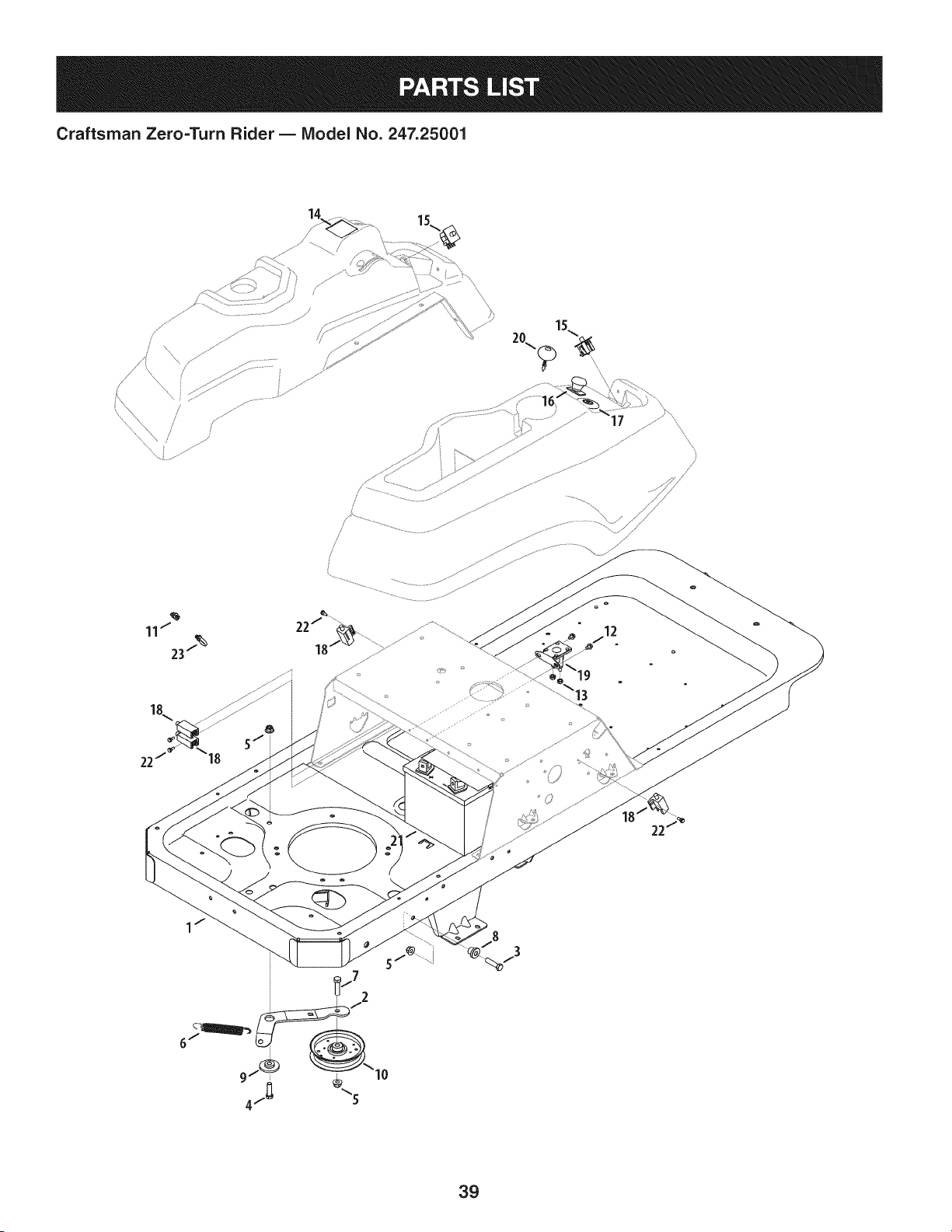
Craftsman Zero=Turn Rider- IViodel No. 247.25001
15..
20\
,\\\
18\
12
1 /
39
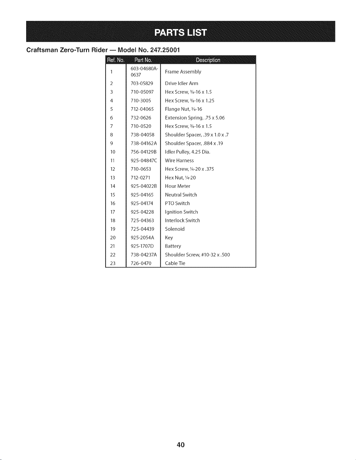
Craftsman Zero=Turn Rider B Model No. 247.25001
1
2
3
4
5
6
7
8
9
10
11
12
13
14
15
16
17
18
19
20
21
22
23
603-04680A-
0637
703-05829
710-05097
710-3005
712-04065
732-0626
710-0520
738-04058
738-04162A
756-04129B
925-04847C
710-0653
712-0271
925-04022B
925-04165
925-04174
925-04228
725-04363
725-04439
925-2054A
925-1707D
738-04237A
726-0470
Frame Assembly
Drive Idler Arm
Hex Screw, 3/8-16 x 1.5
Hex Screw, 3/8-16 x 1.25
Flange Nut, 3/8-16
Extension Spring, .75 x 5.06
Hex Screw, 3/8-16 x 1.5
Shoulder Spacer, .39 x 1.0 x .7
Shoulder Spacer, .884 x .19
Idler Pulley, 4.25 Dia.
Wire Harness
Hex Screw, 1/4-20x .375
Hex Nut, 1/4-20
Hour Meter
Neutral Switch
PTO Switch
Ignition Switch
Interlock Switch
Solenoid
Key
Battery
Shoulder Screw, #10-32 x .500
Ca ble Tie
4O
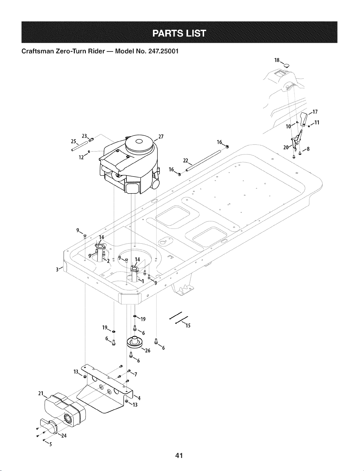
Craftsman Zero=Turn Rider B Model No. 247.25001
18_<_
22
/
/
21
41

Craftsman Zero=Turn Rider B Model No. 247.25001
603-04162 RHExhaustAssembly
2 603-04163 LH ExhaustAssembly
603-04691-
3 0637 FrameAssembly
4 703-05441A MufflerMountBracket
5 710-0227 HexWasherScrew,#8-18x 0.500
6 710-04683 HexWasherScrew,3/8-16x 1.000
7 710-0599 HexWasherScrew,1/4-20x 0.500
8 710-1017 iAB Screw,1/4-14x 0.625
9 710-3008 HexScrew,5/16-18x .75
10 710-3217 MachineScrew,#8-32 x 0.375
11 712-0142 i Hex Nut,#8-32
12 712-0271 iSems Nut, 1/4-20
13 712-04063 iFlangeLockNut,5/16-18
14 721-0460 ExhaustGasket
15 726-0197 CableTie
16 726-0205 HoseClamp,.490
17 731-04914 ThrottleControlKnob
18 731-1999 ChokePlug
19 736-0148 LockWasher,3/8
20 746-04539 Throttle/ChokeControlCable
21 751-0616B DualNet Muffler
22 751-10349 iFuelHose,1/4
23 951-10517A iOil Drain
24 751-11053 iMufflerDeflector
25 751-3141-14 i Oil DrainExtensionHose
26 756-04376 iPTOPulley
445677-0954-
27 G5 iReplacementEngine
42
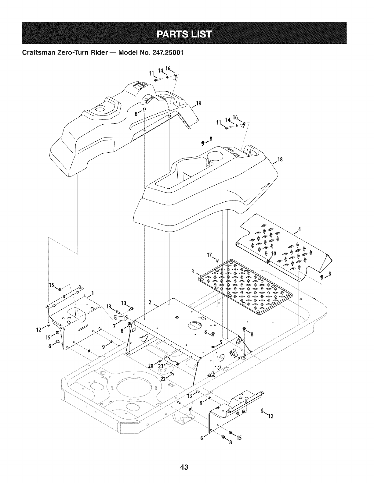
Craftsman Zero=Turn Rider B Model No. 247.25001
19
ii
//
\\
°\15
43

Craftsman Zero=Turn Rider B IViodel No. 247.25001
D = 0 m
603-04564 ConsoleMountBracket
603-04946-
2 SeatFrame
0637
3 735-04082C FootPad
4 703-05373B FootRest
5 736-0148 LockWasher,3/8
6 703-06451 ConsoleMountBracket
703-06623-
7 0637 FuelTankSupportBracket
8 710-04484 HexWasherScrew,5/16-18x .750
9 726-0201 SpeedNut, .3125
10 710-0604A iHexWasherScrew,5/16-18x .825
11 710-0778 HexWasherScrew,1/4-20x 1.500
12 710-0895 HexWasherScrew,1/4-15x .750
13 710-3008 Hex Screw,5/16-18x .75
14 912-0298 i Jam Nut, 1/4-20
15 712-04063 iFlangeLockNut,5/16-18
16 712-04092 iU-TypeNut, 1/4-20
17 726-3046 RatchetClip, .250
18 731-06233 RHConsole
19 731-06263B LH Console
20 710-0599 HexScrew,1/4-20x .5
703-05894-
21 0637 iBatteryHold-Down
22 731-0511 iTrimStrip
44
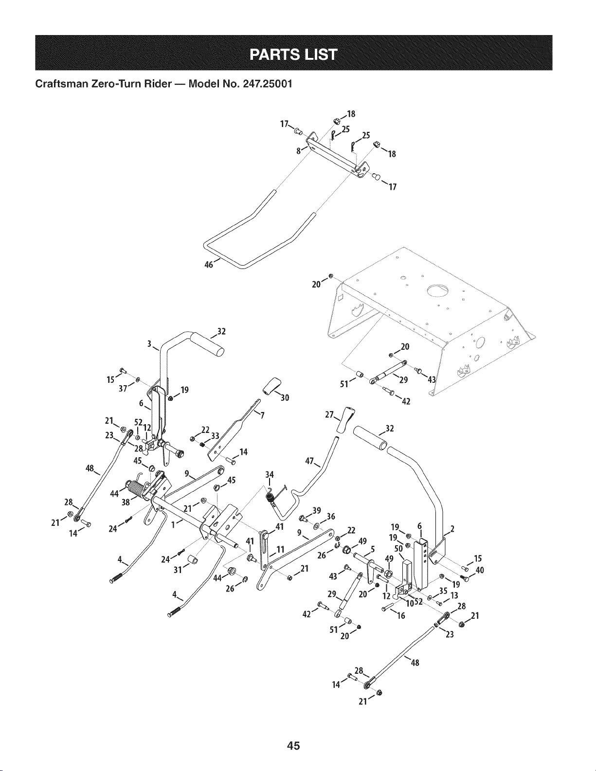
Craftsman Zero=Turn Rider B Model No. 247.25001
/
/
/ /
/ /
/
/
20/_"
17
48
34
2O
42
45

Craftsman Zero=Turn Rider B IViodel No. 247.25001
D = 0 m
603-04160B-
1 0637 DeckLift ShaftAssembly
603-04322-
2 0637 LapbarLeverRH
603-04324-
3 0637 LapbarLeverLH
4 947-04065 BrakeRod(42"& 50" Decks)
5 647-04099A ControlShaft
6 703-05387B LapbarPivotBracket
703-05396A-
7 BrakeHandle
0637
703-05414A-
8 4044 FrontDeckHangerBracket
703-05793A-
9 DeckLift Arm
4044
10 703-06096A SwitchActuatorBracket
703-06169-
11 Lift LinkPlate
0637
12 710-0347 Hex Screw,3/8-16x 1.75
13 710-0433 Hex LockScrew,1/4-20x .62
14 710-3005 Hex CapScrew,3/8-16x 1.25
15 710-3008 Hex CapScrew,5/16-18x .75
16 710-3180 Hex CapScrew,5/16-18x 1.75
17 911-0332 ClevisPin,.50x .78
18 712-04243 HexNut, 1/2-13
19 712-04063 HexFlangeinsert Lock Nut,5/16-18
20 712-04064 HexFlangeInsertLockNut,1/4-20
21 712-04065 HexFlangeinsertLockNut,3/8-16
22 712-0375 HexLockNut,3/8-16
23 912-3001 JamNut,3/8-24
24 714-04040 Bow-TieCotterPin
914-04023
26 716-0106
27 720-0311
28 723-04035
29 727-04141
30 731-04735
31 731-05732
32 720-0274
33 932-0334
34 732-0874
35 736-0270
36 936-0272
37 936-0275
38 732-04420
39 738-0143
40 938-0296
41 938-0507B
42 938-0572
43 938-0974
44 941-0225
45 741-3074
46 747-04401A
47 747-04637
48 747-05057
49 948-0227A
50 748-04169A
51 750-04676
52 750-04776
D = O O
Cotter Pin
E-Ring,.625 Dia.
HandleGrip
RodEnd
DamperCylinder
HandleGrip
Spacer,.62x 1.0
HandGrip
CompressionSpring
TorsionSpring
BellWasher,.265x .75x .062
FlatWasher,.51x 1.0x .06
FiatWasher,.344x .688x .065
TorsionSprg.,LH (50"&54" Decks)
ShoulderScrew,.498x .340x 3/8-16
ShoulderScrew,.437x .268x 5/16-18
ShoulderScrew,.5 x .434x 3/8-16
ShoulderScrew,.374x 1.16x 1/4-20
ShoulderScrew,.375x .38x 1/4-20
HexFlangeBearing
FlangeBearing,.626x .938x .344
DeckFrontHangerRod
DeckLiftHandleRod
LapbarControlRod
HexFlangeBearing
ControlHub
Spacer,.385x .630x .75
Spacer,.380x .625x .265
46
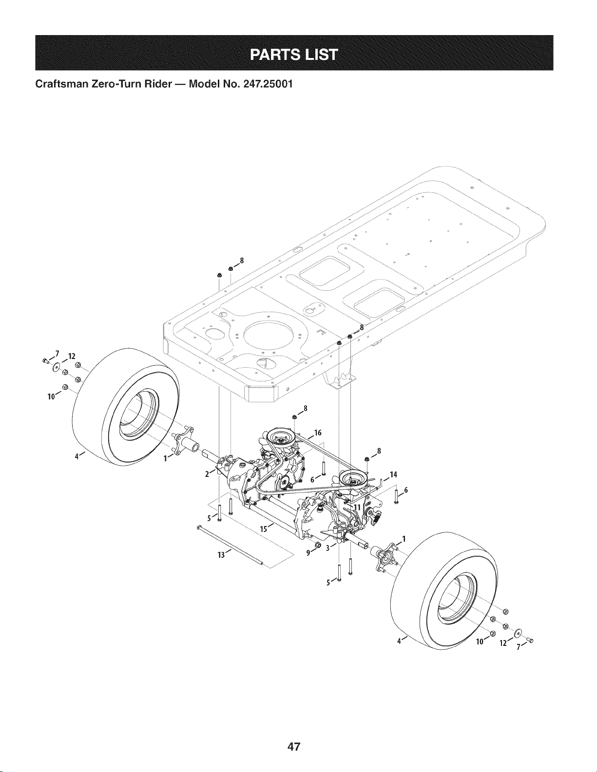
Craftsman Zero=Turn Rider B IViodel No. 247.25001
47

Craftsman Zero=TurnRider B Model No.247.25001
918-04317
2 918-04431B
3 918-04432B
634-04293-
4
0961
5 710-0176
6 710-0395
7 710-3119
8 712-04063
9 712-0459
10 712-3050
11 714-04040
12 936-0227
13 738-04192
747-04217C-
14
0637
15 750-04561
D = O O
WheelHub,7/16-14x 1.6
TransmissionAssembly,LH
TransmissionAssembly,RH
WheelAssembly,18x 8.5-8
iHexCapScrew,5/16-18x 2.75
iHexCapScrew,5/16-18x 2.25
iHexCapScrew,3/8-16x .75
iHexFlangeNut,5/16-18
iHexFlangeNut,7/16-20
iLugNut,7/16-14
Bow-TieCotterPin
FlatWasher,.39x 1.5
iRod,.405x 14
BypassRod
iTube,.45x .69x 10.2
16 954-04043A V-Belt
48
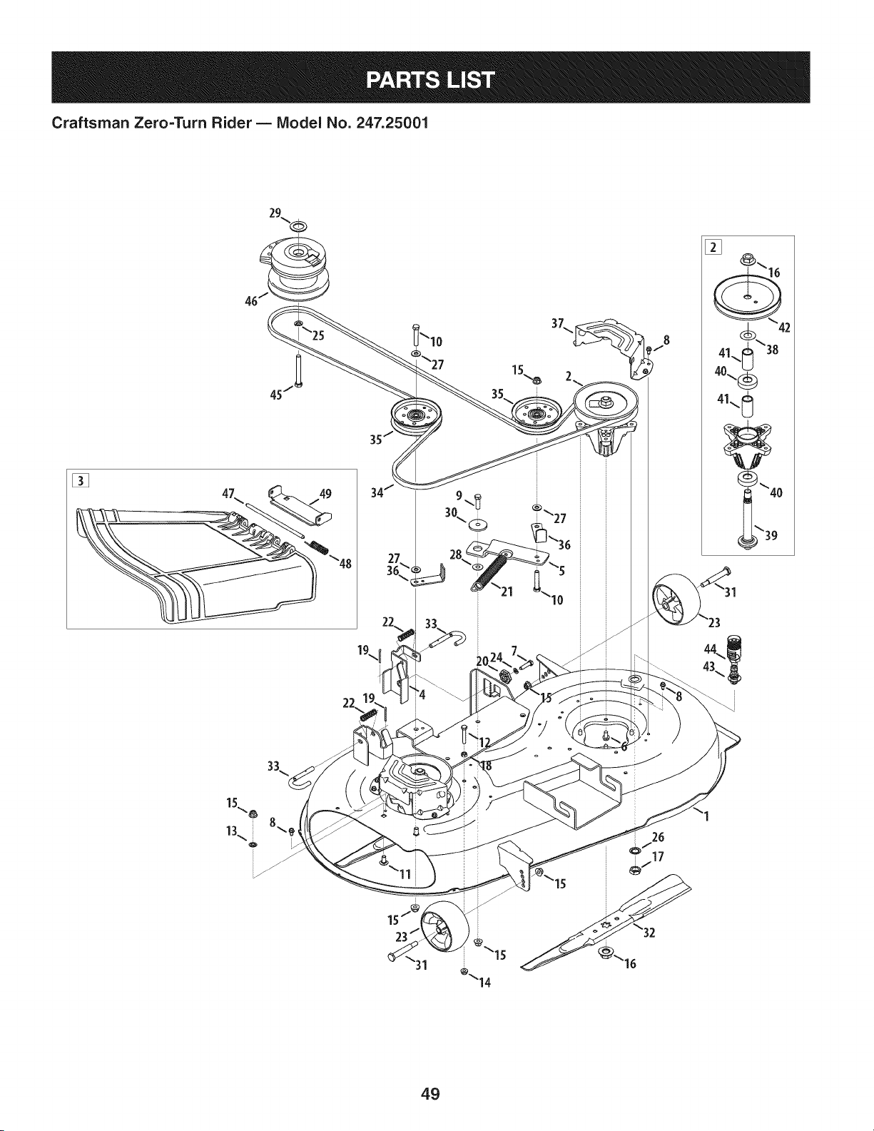
Craftsman Zero=Turn Rider B IViodel No. 247.25001
[]
31
``14
26
f
17
49

Craftsman Zero=Turn Rider B Model No. 247.25001
903-04860-
1 4044 DeckHousing
2 918-04822A SpindleAssembly
3 631-04288 DischargeChuteAssembly
683-0254B-
4 DeckLift Bracket
4044
5 703-08336A PivotldlerBracket
6 710-04484 HexWasherHeadScrew,5/16-18x .750
7 710-0528 HexCapScrew,5/16-18x 1.25
8 710-0599 HexWasherHeadScrew,1/4-20x .5
9 710-3005 HexCapScrew,3/8-16x 1.25
10 710-3144 Hex CapScrew,3/8-16x 2.00
11 710-3178 CarriageScrew,3/8-16x .75
12 710-3180 Hex CapScrew,5/16-18x 1.75
13 712-0229 PushNut,3/8
14 712-04063 FlangeLockNut, 5/16-18
15 712-04065 FlangeLockNut, 3/8-16
16 712-0417A Hex FlangeNut,5/8-18
17 912-0641 Hex Nut, M16-1.5
18 912-3010 Hex Nut,5/8-18
19 914-0470 CotterPin,1/8x 1.25
20 917-04074 DeckAdjustmentGear
21 732-0459C ExtensionSpring,.94Dia.x 6.74
22 732-04652 CompressionSpring,.535x 1.751
23 734-04155 DeckBallWheel,5.0
24 936-0119 LockWasher,5/16
25 936-0171 LockWasher,7/16
D = O
736-0225 internalToothLockWasher,5/8
i27 736-0262 FlatWasher,.385x .870x .092
i28 936-0344 FlatWasher,.385x 1.00x .030
i29 736-0277 FiatWasher,1.031x 1.620x .095
i30 738-04162A ShoulderSpacer,.884x.190
i31 938-3056 ShoulderScrew,.5 x 2.5 x 3/8-16
i32 942-04308 Blade,2 in 1,21.23
i33 747-1116 DeckHangerRod
i34 954-04137A V-Belt
i35 756-04129B IdlerPulley,4.25 Dia.
783-06368A-
i36 4044 Bracket,Belt Guard
i37 783-06424A- BeltCover
4044
i38 936-0351 Washer,.760x 1.50x .030
i39 738-1186A SpindleShaft
i40 941-0919A BallBearing
i41 750-04936 Spacer,.792x 1.060x 1.860
i42 956-1227 DeckPulley
i43 737-04003D DeckWaterNozzle
i44 921-04041 WaterNozzleAdapter
i45 710-3157A Screw,7/16-20x 3.25
i46 917-04376A PTOElectricClutch
i47 711-04847B HingePin
i48 732-04372 TorsionSpring
i49 783-06074A ChuteBracket
5O
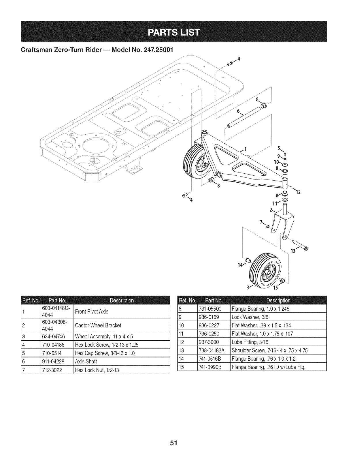
Craftsman Zero=Turn Rider B IViodel No. 247.25001
f
13
14/
603-04148C-
1 4044 FrontPivotAxle
2 i603-04308- CastorWheelBracket
4044
3 634-04746 WheelAssembly,11x 4 x 5
4 710-04186 HexLockScrew,1/2-13x 1.25
5 710-0514 HexCapScrew,3/8-16x 1.0
6 911-04228 Axle Shaft
7 712-3022 HexLockNut, 1/2-13
9
10
11
12
13
14
15
731-05500
936-0169
936-0227
736-0250
937-3000
738-04182A
741-0516B
741-0990B
D = _
FlangeBearing,1.0x 1.246
LockWasher,3/8
FlatWasher,.39x 1.5x .134
FlatWasher,1.0x 1.75x .107
LubeFitting,3/16
ShoulderScrew,7/16-14x .75x 4.75
iFlangeBearing,.76x 1.0x 1.2
iFlangeBearing,.76ID w/LubeFtg.
51
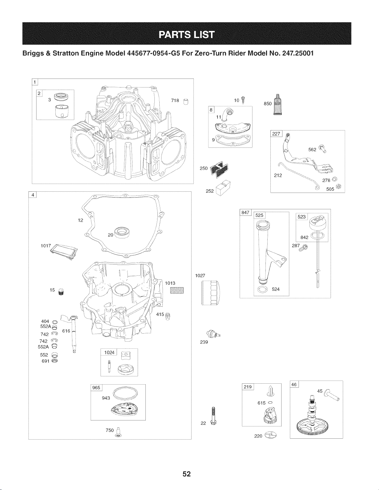
Briggs & Stratton Engine IViodel 445677=0954=G5 For Zero=Turn Rider IViodel No. 247.25001
250 _,
252
10 _ 850
1013
404 @ _\_
552A5_--i
742 d_ 616_
742 d_;_ i i
552A ¢_
552
691
750 f::_
d_-_
1027
239
22
_ 524
_..........................................................J
4y
45
22o_._
52
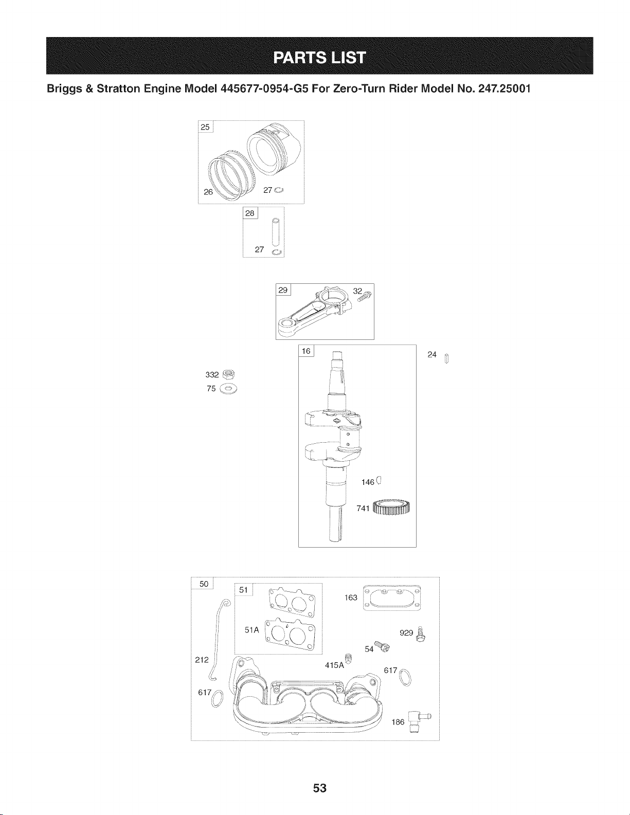
Briggs & Stratton Engine Model 445677-0954-G5 For Zero=Turn Rider Model No. 247.25001
' r
i25
26
27 <>
27 _,_
332 ':-_-:_
75 %_::_
146(_
741
24
" 50 [ 1777¸¸¸17777777777777771
_51
L
//
ff
51A 929 _
54_
_J
JJ
163 ::@/'- _4;
< /
1_::,t:
186
53
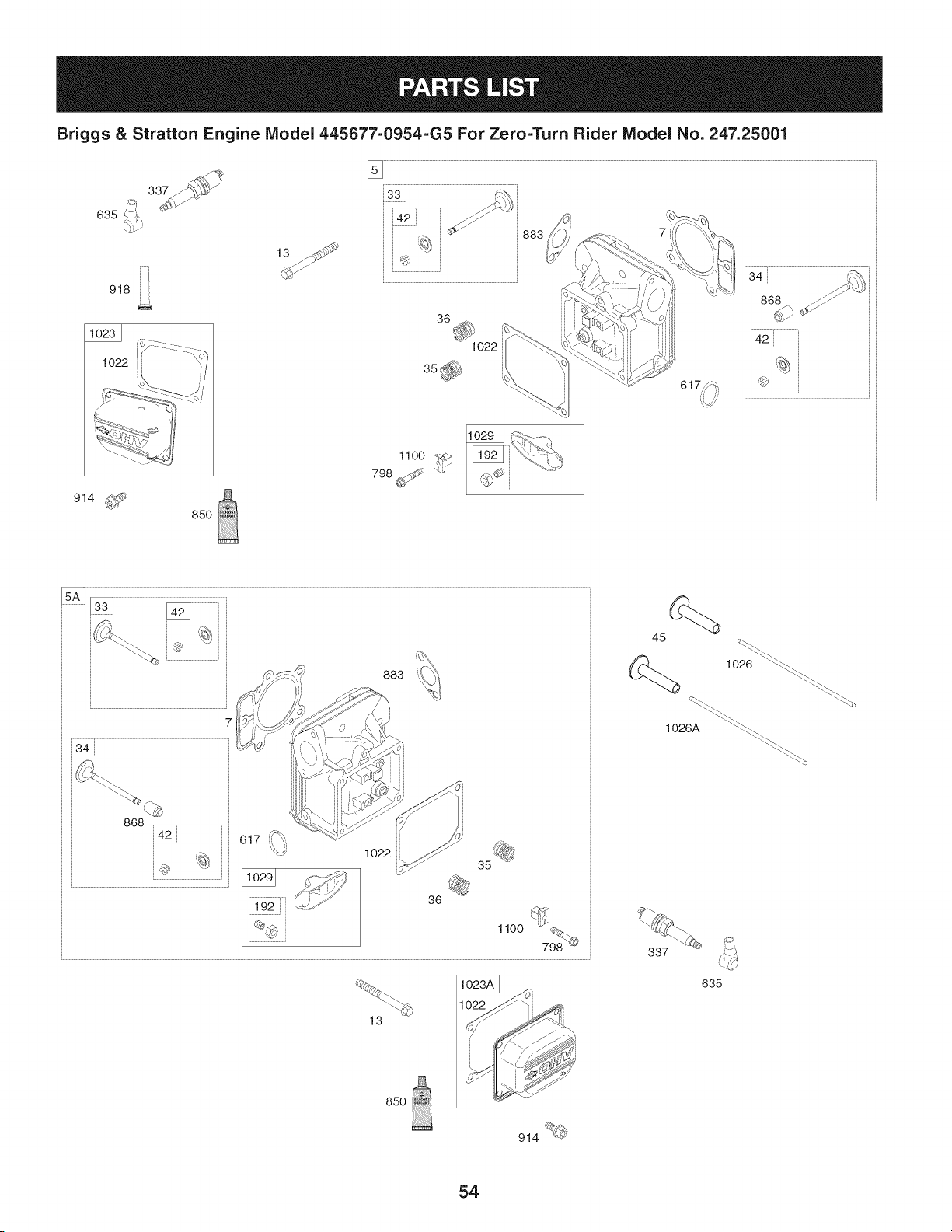
Briggs & Stratton Engine IViodel 445677=0954-G5 For Zero=Turn Rider IViodel No. 247.25001
%
i
635
i
918 i
J1
1022 i
914 _
850
1O22
883
883
1o22
36
1lOO
13
85o
914 _®'
qt_
1026 _._.
"_._
1026A "'_.
337
635
54
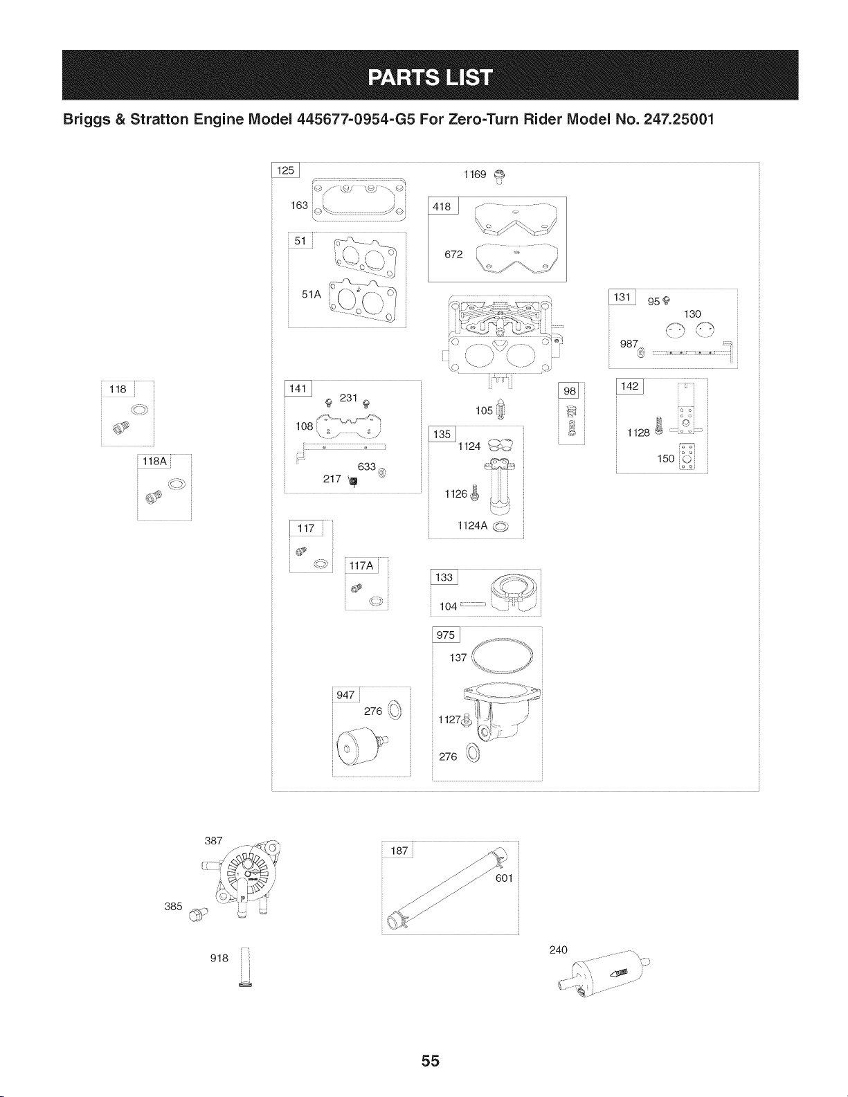
Briggs & Stratton Engine Model 445677=0954=G5 For Zero=Turn Rider Model No. 247.25001
118
118A [
163 _. ...... ic_
\ J
k.,,\-/( ] "7
:: o'_c--j /
9 231 9
108
633 @
217 _l!I
_::_ 117A
4]_ _-......... , .......
/ ,y?_/ ........\ '..
k id'
105 ;I' "
1126
1124A (.__
130
\ ) \
987 ;;;;;;_
UY
276 Y_<_2
r-< _ _ _S '_
1127_......_li'-i.il,, ) °_:":i
z_
276 _Jx
385
387
918
601
24O
55
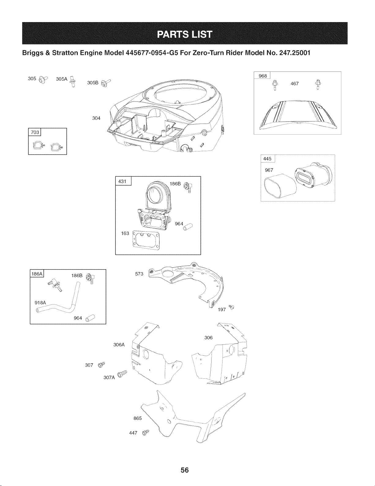
Briggs & Stratton Engine Model 445677=0954-G5 For Zero=Turn Rider Model No. 247.25001
304
4
163
// i
/
/
/
467
445
967
186A_ 186B _
9_8A........... ///
__-:::...........-. _/
964 (,_
573
3O7
306A
306
56
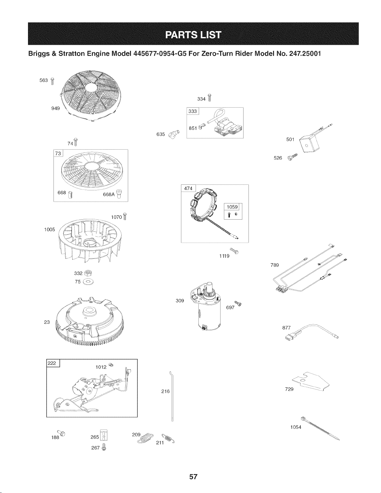
Briggs & Stratton Engine IViodel 445677-0954-G5 For Zero=Turn Rider IViodel No. 247.25001
563
949
334
74_ 501
526 @_
1005
23
1070
332 f_
75 (_ >_
1119
2
,.. _ 697%
789
877 /_: ........._'_
i
216
c. _- .
729 :::::
209_,#<_ 21_ _
1054 _'_
57
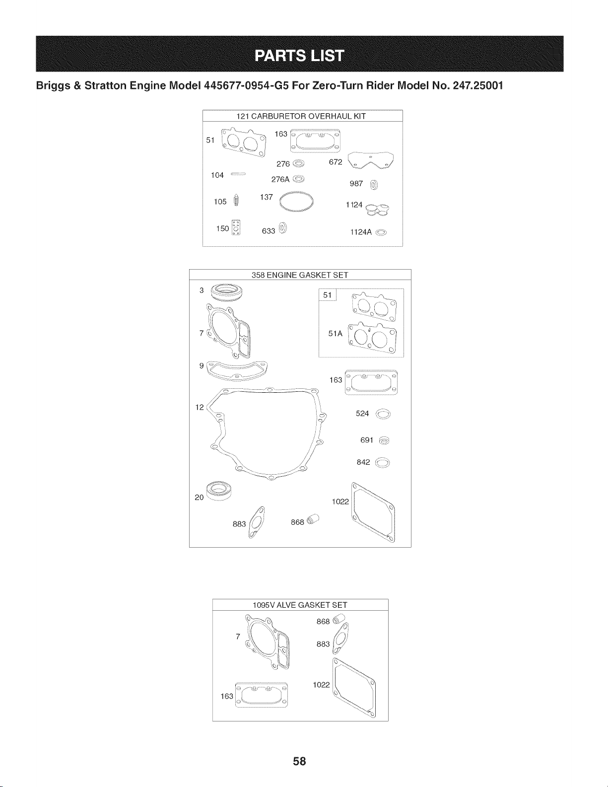
Briggs & Stratton Engine Model 445677-0954-G5 For Zero=Turn Rider Model No. 247.25001
121 CARBURETOR OVERHAUL KIT
51
_i_=_ _ _7:_ P_=_
163 i>f <:_ ,,_ "_>i
i i i i
k_\..........................................._i
r...........7................q
276 d*_' 672 k,,<,./_ ::;/ '
104
276A _::<'#
987 4;,_
,,:_jj
_ 137f .............._,
1o5
w
1124 f,,,,,J_:--_
%,,,/" /
15o i_$i 633 ','_; 1124A c{7
12
2O
", t
524 #:::_
,_ //'
691 _p::::::_
842 K;:::_
1o22
883
1095V ALVE GASKET SET
868 __i
883,!_
163[ .... j_i
1o22
58

Briggs & Stratton Engine IViodel 445677=0954=G5 For Zero=Turn Rider IViodel No. 247.25001
793564 CylinderAssembly 699721 Kit-IdleSpeed
2 797673 Bushing/SealKit(MagnetoSide) i104 694918 Pin-FloatHinge
3 391086s Seal-Oil(MagnetoSide) 105 797410 Valve-FloatNeedle
4 796307 Sump-Engine 108 699723 Valve-Choke
5 796231 Head-Cylinder(Cylinder1) 117 792296 Jet-Main(Standard)(Left Jet)
5A 796232 Head-Cylinder(Cylinder2) 117A1842627 Jet-Main(Standard)(RightJet)
7 693997 Gasket-CylinderHead 118 699457 Jet-Main(High Altitude)(LeftJet)
8 792185 BreatherAssembly i118A 699733 Jet-Main(High Altitude)(RightJet)
9 690937 Gasket-Breather 121 797890 Kit-CarburetorOverhaul
10 691108 Screw(BreatherAssembly) i125 796227 Carburetor
11 792184 Tube-Breather 130 690993 Valve-Throttle
12 697227 Gasket-Crankcase i131 499805 Kit-ThrottleShaft
13 793988 Screw(CylinderHead) 133 699724 Float-Carburetor
15 794903 Plug-OilDrain 135 699729 Tube-FueITransfer
16 796237 Crankshaft 137 690994 Gasket-FloatBowl
20 795387 Seal-Oil(PTOSide) 141 i796228 Kit-ChokeShaft
22 694966 Screw(CrankcaseOover/Sump) 142 699726 Nozzle-Carburetor
23 799090 Flywheel i146 690979 Key-Timing
24 222698s Key-Flywheel(Aluminum) 150 690995 Gasket-Nozzle
25 792023 PistonAssembly(Standard) 163 691001 Gasket-AirCleaner
792072 PistonAssembly(020"Oversize) 186 795985 Hose-Connector(IntakeManifold)
26 792026 RingSet (Standard) 186A 799158 Hose-Connector(EVAPSystem)
792073 RingSet (.020"Oversize) 186B1845141 Hose-Connector
27 690975 Lock-PistonPin 187 791766 Line-Fuel(Cutto RequiredLength)
28 696581 Pin-Piston 188 691108 Screw(ControlBracket)
29 796209 Rod-Connecting 192 690083 Adjuster-RockerArm
32 690976 Screw(ConnectingRod) 197 697820 Screw(BackPlate)
33 697576 Valve-Exhaust 209 1799171 Spring-Governor(LightBlue)
34 792200 Valve-Intake 211 691019 Spring-GovernedIdle(l/0 Color)
35 694865 Spring-Valve(Intake) 212 695238 Link-Throttle
36 694865 Spring-Valve(Exhaust) 216 796229 Link-Choke
42 499586 Keeper-Valve 217 799112 Spring-ChokeReturn
45 690977 Tappet-Valve 219 793338 Gear-Governor
46 792555 Camshaft 220 799772 Washer(GovernorGear)
48 N/A ShortBlock (Not AvailableAt This Printing) 221 i841026 Cup-Governor
50 695241 Manifold-Intake 222 798915 Bracket-Control
51 795123 Gasket-Intake 227 798856 Lever-GovernorControl
51A 690950 Gasket-Intake 231 690718 Screw(ChokeValve)
53 690951 Stud(Carburetor) 239 792028 Switch-OilPressure
54 699816 Screw(IntakeManifold) 240 695666 Filter-Fuel
73 494439 Screen-Rotating 250 690957 Retainer-Breather
74 698425 Screw(RotatingScreen) 252 794389 Collector-Oil
75 691056 Washer(Flywheel) 265 691024 Clamp-Casing
95 690718 Screw(ThrottleValve) 267 792629 Screw(CasingClamp)
59

Briggs & Stratton Engine IViodel 445677=0954=G5 For Zero=Turn Rider IViodel No. 247.25001
695410 Washer-Sealing 697891 SeaI-ORing(IntakeManifold)(Red)
i278 792651 Washer(GovernorControlLever) 633 699813 Seal-Choke/ThrottleShaft(ChokeShaft)
i287 691108 Screw(DipstickTube) 635 66538s Boot-SparkPlug
i304 799955 Housing-Blower 654 690958 Nut(Carburetor)
i305 691005 Screw(BIowerHousing)(1/4-20x.68) 668 691215 Spacer(RotatingScreen)
i305A 698336 Screw(BlowerHousing) 668A 691500 Spacer(RotatingScreen)
i305B 790690 Screw(BlowerHousing)(BlowerHousingto 672 690234 Gasket-CarburetorPlate
IntakeElbow) 691 790574 Seal-GovernorShaft
306 798855 Shield-Cylinder(Cylinder2) 697 791680 Screw(DriveCap)
306A 796852 Shield-Cylinder(Cylinder1) 703 691010 Clip
307 691003 Screw(CylinderShield)(10-24x.43) 718 690959 Pin-Locating
307A 691108 Screw(CylinderShield)(1/4-20x.66) 729 797454 Clip-Wire
309 590476 Motor-Starter 741 690980 Gear-Timing
332 691059 Nut(Flywheel) 742 690328 Retainer-ERing
333 799651 Armature-Magneto 750 796208 Screw(Oil PumpCover)
334 691061 Screw(MagnetoArmature) 789 698330 Harness-Wiring
337 793541 Plug-Spark 798 697890 Screw(RockerArm)
358 694012 GasketSet-Engine 842 691031 SeaI-ORing(Dipstick)
385 797409 Screw(Fuel Pump) 847 499602 Dipstick/TubeAssembly
387 808656 Pump-Fuel 850 100106 Sealant-Liquid
404 690442 Washer(GovernorCrank) 851 493880s Terminal-SparkPlug
415 794903 Plug 865A 792286 Cover-AirGuide(Valley)
415A 794903 Plug(IntakeManifold) 868 690968 Seal-Valve
418 795912 Plate-Carburetor 877 790544 Wire/Connector-Alternator
431 798860 Elbow-Intake 883 690970 Gasket-Exhaust
445 792105 Filter-AirCleanerCartridge 914 691127 Screw(RockerCover)
447 691003 Screw(AirGuide Cover) 918 797408 Hose-Vacuum(RockerCover)
462 691261 Washer(StarterCable) 918A 799160 Hose-Vacuum(EVAPSystem)
467 790697 Knob-AirCleaner 929 695239 Screw(ChokeControlBracket)
474 696457 Alternator 943 796222 SeaI-ORing(Oil PumpCover)
501 794360 Regulator 947 798779 Solenoid-Fuel
505 691029 Nut(GovernorControlLever) 949 798767 Guard-DebrisScreen
523 691036 Dipstick 964 799159 Cap-Connector
524 691032 SeaI-DipstickTube 965 796221 Cover-OilPump
525 691037 Tube-Dipstick 967 792303 Filter-PreCleaner
526 691129 Screw(Regulator) 968 795120 Cover-AirCleaner
552 796638 Bushing-GovernorCrank 975 798778 Bowl-Fuel
552A 690553 Bushing-GovernorCrank 987 691000 SeaI-ThrottleShaft
562 690311 Screw(GovernorControlLever) 1005 791236 Fan-Flywheel
563 799359 Screw(DebrisScreenGuard)(#8-18x.875) 1012 797926 Retainer-Link
573 790444 Plate-Back 1013 690954 Nipple-OilFilter
601 691038 Hose-Clamp(Black) 1017 796214 Screen-OilPump
615 698290 Retainer-GovernorShaft 1022 690971 Gasket-RockerCover
616 691045 Crank-Governor 1023 793146 Cover-Rocker(Cylinder#1)
6O

Briggs & Stratton Engine IViodel 445677=0954=G5 For Zero=Turn Rider IViodel No. 247.25001
499600 Cover-Rocker(Cylinder#2)
1024 796220 Pump-Oil
1026 690981 Rod-Push(Steel)(Exhaust)
1026A690982 Rod-Push(Aluminum)(Intake)
1027 795890 Filter-Oil
1029 690972 Arm-Rocker
Label-Emissions(Availablefrom a Briggs&
1036
StrattonAuthorizedDealer)
1054 280275 Tie-Cable
1058 278776TRI
1059 698516 Kit-Screw/Washer(Alternator)
1070 791680 Screw(FlywheelFan)
1095 694013 GasketSet-Valve
1000 791959 Pivot-RockerArm
1119 691183 Screw(Alternator)
1124 690988 SeaI-ORing(FuelTransferTube)
1124A841653 SeaI-ORing(FuelTransferTube)
1126 690991 Screw(FuelTransferTube)
1127 695407 Screw(FloatBowl)
1128 690990 Screw(CarburetorNozzle)
1169 690990 Screw(CarburetorCoverPlate)
1330 273521 RepairManual
61
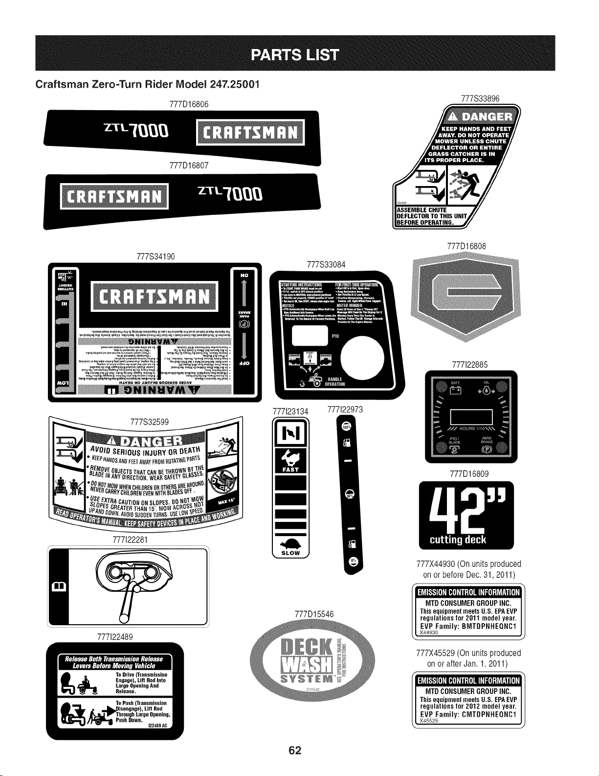
Craftsman Zero=Turn Rider IViodel 247.25001
777D16806 777333896
777D16807
777S34190
777S33084
777D16808
777122885
777332599
777122281
777123134
777122973
777D16809
777X44930 (On units produced
on or before Dec. 31,2011)
f 11 11 I _ I f i:iilf,"_1[ ]_l_ ]_1i;{ ]IId_[ ]:tuPli[ i
777122489
777D15546
MTDCONSUMERGROUPINC.
Thisequipment meets U.S. EPAEVP
regulations for 2011 model year.
EVPFamily:BMTDPNHEQNC1
X44930
777X45529 (On units produced
on or after Jan. 1,2011)
T I 1 I 1 I _ I v I:uI_,$1[]_I_]_ii1{]II_II[]:IuEti[I
MTDCONSUMERGROUPINC.
Thisequipment meets U.S. EPAEVP
regulations for 2012 model year.
EVPFamily:CMTDPNHEQNC1
X45529
62

This page intentionally left blank. Use this page to make any notes regarding your tractor.
63
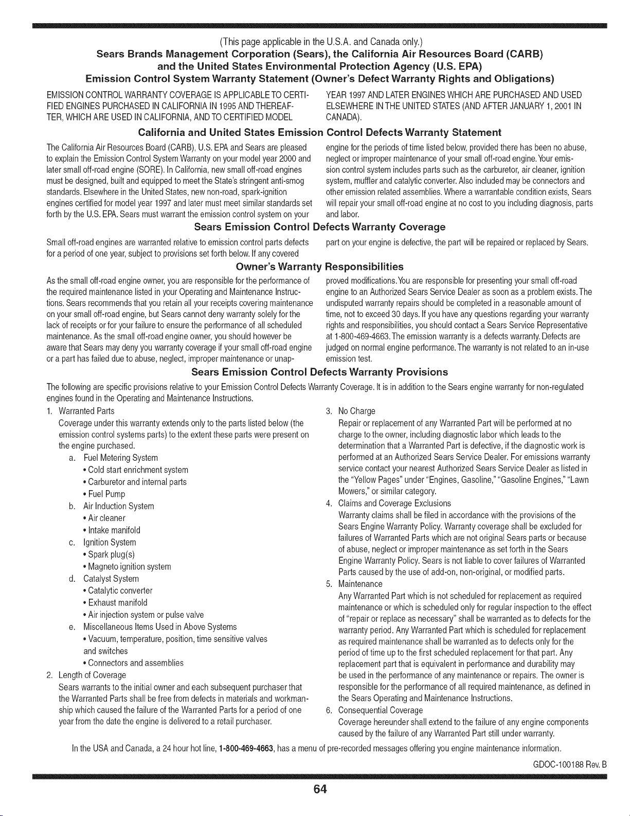
(Thispageapplicablein the U.S.A.and Canadaonly.)
Sears Brands Management Corporation (Sears), the California Air Resources Board (CARD)
and the United States Environmental Protection Agency (U.S. EPA)
Emission Control System Warranty Statement (Owner's Defect Warranty Rights and Obligations)
EMISSIONCONTROLWARRANTYCOVERAGEISAPPLICABLETOCERTI-
FIEDENGINESPURCHASEDINCALIFORNIAIN 1995ANDTHEREAF-
TER,WHICHARE USED INCALIFORNIA,ANDTOCERTIFIEDMODEL
California and United States Emission
The CaliforniaAir ResourcesBoard(CARD),U.S.EPAand Searsare pleased
to explainthe EmissionControlSystemWarrantyon your modelyear2000and
latersmalloff-roadengine(SORE).InCalifornia,newsmall off-roadengines
mustbe designed,builtand equippedto meettheState'sstringentanti-smog
standards.Elsewherein the UnitedStates, newnon-road,spark-ignition
enginescertifiedfor modelyear 1997and latermustmeetsimilarstandardsset
forth bythe U.S.EPA.Sears mustwarrantthe emissioncontrol systemonyour
YEAR 1997AND LATERENGINESWHICHARE PURCHASEDANDUSED
ELSEWHEREINTHE UNITEDSTATES(ANDAFTERJANUARY1,2001 IN
CANADA).
Control Defects Warranty Statement
enginefor the periodsoftime listedbelow,providedtherehas been noabuse,
neglector impropermaintenanceof your smalloff-roadengine.Youremis-
sion controlsystemincludespartssuch as thecarburetor,air cleaner,ignition
system,mufflerand catalyticconverter.Also includedmay be connectorsand
otheremissionrelatedassemblies.Wherea warrantableconditionexists,Sears
will repairyour smalloff-roadengineat nocostto you includingdiagnosis,parts
and labor.
Sears Emission Control Defects Warranty Coverage
Smalloff-roadenginesarewarrantedrelativeto emissioncontrol partsdefects
fora period of one year,subjectto provisionsset forthbelow.Ifany covered
Owner's Warranty
Asthe smalloff-roadengine owner,you are responsiblefor the performanceof
therequiredmaintenancelistedin yourOperatingand MaintenanceInstruc-
tions.Searsrecommendsthatyou retain all yourreceiptscoveringmaintenance
on yoursmalloff-roadengine,but Sears cannotdenywarrantysolelyfor the
lackof receiptsorfor yourfailureto ensurethe performanceof all scheduled
maintenance.As the smalloff-roadengineowner,you shouldhoweverbe
awarethat Searsmaydenyyou warrantycoverageif your smalloff-roadengine
ora part hasfaileddueto abuse,neglect,impropermaintenanceor unap-
parton yourengineis defective,the part willbe repairedor replacedbySears.
Responsibilities
provedmodifications.Youare responsiblefor presentingyour smalloff-road
engineto an AuthorizedSearsServiceDealeras soonas a problemexists.The
undisputedwarrantyrepairsshouldbe completedina reasonableamountof
time,not to exceed30 days. Ifyou haveany questionsregardingyourwarranty
rightsand responsibilities,you shouldcontacta SearsService Representative
at 1-800-469-4663.The emissionwarrantyis a defectswarranty.Defectsare
judgedon normalengineperformance.The warrantyis notrelatedto an in-use
emissiontest.
Sears Emission Control Defects Warranty Provisions
ThefollowingarespecificprovisionsrelativetoyourEmissionControlDefectsWarrantyCoverage.Itisin additiontotheSearsenginewarrantyfornon-regulated
enginesfound in theOperatingand MaintenanceInstructions.
1. WarrantedParts
Coverageunderthis warrantyextendsonly to the parts listedbelow (the
emissioncontrolsystemsparts)to the extentthese partswere presenton
theengine purchased.
a. FuelMeteringSystem
• Cold start enrichmentsystem
• Carburetorand internalparts
• FuelPump
b. Air lnduction System
• Air cleaner
• Intakemanifold
c. IgnitionSystem
• Spark plug(s)
• Magnetoignitionsystem
d. CatalystSystem
• Catalyticconverter
• Exhaustmanifold
• Air injectionsystemor pulsevalve
e. MiscellaneousItemsUsedin AboveSystems
• Vacuum,temperature,position,timesensitivevalves
andswitches
• Connectorsandassemblies
2. Lengthof Coverage
Searswarrantsto the initialownerand eachsubsequentpurchaserthat
theWarrantedPartsshallbe free fromdefects in materialsandworkman-
shipwhich causedthe failure of the WarrantedPartsfor a periodof one
yearfromthe datethe engineis deliveredto a retailpurchaser.
3. NoCharge
Repairor replacementof anyWarrantedPartwill be performedat no
chargeto the owner,includingdiagnosticlabor whichleads to the
determinationthata WarrantedPartis defective,if the diagnosticwork is
performedat an AuthorizedSearsServiceDealer.For emissionswarranty
servicecontact yournearestAuthorizedSears ServiceDealeras listed in
the "YellowPages"under"Engines,Gasoline,""GasolineEngines,""Lawn
Mowers,"orsimilar category.
4. Claimsand CoverageExclusions
Warrantyclaimsshall be filed in accordancewiththe provisionsof the
Sears EngineWarrantyPolicy.Warrantycoverageshall be excludedfor
failuresof WarrantedPartswhichare notoriginal Sears partsor because
of abuse,neglector impropermaintenanceas setforth inthe Sears
EngineWarrantyPolicy.Sears is notliableto coverfailuresof Warranted
Partscausedby the use of add-on,non-original,or modifiedparts.
5. Maintenance
Any WarrantedPart whichis notscheduledfor replacementas required
maintenanceor whichis scheduledonly for regularinspectionto the effect
of "repairor replaceas necessary"shallbe warrantedas to defectsfor the
warrantyperiod.Any WarrantedPartwhich is scheduledfor replacement
as requiredmaintenanceshallbe warrantedas to defectsonly forthe
periodof time upto the first scheduledreplacementfor that part. Any
replacementpart that is equivalentin performanceand durabilitymay
be usedin the performanceof any maintenanceor repairs.The owneris
responsibleforthe performanceof all requiredmaintenance,as definedin
the SearsOperatingand MaintenanceInstructions.
6. ConsequentialCoverage
Coveragehereundershallextend to thefailure of any enginecomponents
caused bythe failureof any WarrantedPartstill underwarranty.
Inthe USAandCanada,a 24 hour hot line, 1-800-469-4663,has a menuof pre-recordedmessagesofferingyou enginemaintenanceinformation.
GDOC-100188Rev.B
64
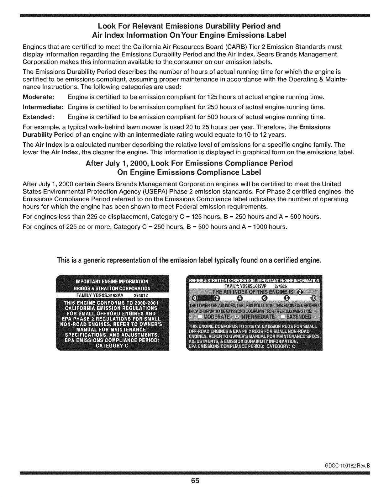
Look For Relevant Emissions Durability Period and
Air index information On Your Engine Emissions Label
Engines that are certified to meet the California Air Resources Board (CARB) Tier 2 Emission Standards must
display information regarding the Emissions Durability Period and the Air Index. Sears Brands Management
Corporation makes this information available to the consumer on our emission labels.
The Emissions Durability Period describes the number of hours of actual running time for which the engine is
certified to be emissions compliant, assuming proper maintenance in accordance with the Operating & Mainte-
nance Instructions. The following categories are used:
Moderate: Engine is certified to be emission compliant for 125 hours of actual engine running time.
Intermediate: Engine is certified to be emission compliant for 250 hours of actual engine running time.
Extended: Engine is certified to be emission compliant for 500 hours of actual engine running time.
For example, a typical walk-behind lawn mower is used 20 to 25 hours per year. Therefore, the Emissions
Durability Period of an engine with an intermediate rating would equate to 10 to 12 years.
The Air index is a calculated number describing the relative level of emissions for a specific engine family. The
lower the Air Index, the cleaner the engine. This information is displayed in graphical form on the emissions label.
After July 1,2000, Look For Emissions Compliance Period
On Engine Emissions Compliance Label
After July 1, 2000 certain Sears Brands Management Corporation engines will be certified to meet the United
States Environmental Protection Agency (USEPA) Phase 2 emission standards. For Phase 2 certified engines, the
Emissions Compliance Period referred to on the Emissions Compliance label indicates the number of operating
hours for which the engine has been shown to meet Federal emission requirements.
For engines less than 225 cc displacement, Category C = 125 hours, B = 250 hours and A = 500 hours.
For engines of 225 cc or more, Category C = 250 hours, B = 500 hours and A = 1000 hours.
This is a generic representation of the emission label typically found on a certified engine.
FAMILYYBSXS.3192VA 274812
GDOC-100182Rev.B
65
FEDERAL and/or CALIFORNIA EMISSION CONTROL WARRANTY STATEMENT
YOUR WARRANTY RIGHTS AND OBLIGATIONS
MTDConsumerGroupInc,the UnitedStatesEnvironmentalProtectionAgency (EPA),and, forthose productscertifiedfor sale in the stateof California,the
CaliforniaAir ResourcesBoard(CARB)are pleasedto explainthe emission(evaporativeand/or exhaust)controlsystem(ECS) warrantyon youroutdoor 2006
andlater smalloff-roadspark-ignitedengine andequipment(outdoorequipmentengine)In California,new outdoorequipmentengines mustbe designed,built and
equippedto meetthe State'sstringentanti-smogstandards(in otherstates, 1997andlater modelyear equipmentmustbe designed,built, and equippedto meet
theU.S. EPAsmalloff-road, sparkignitionengine regulations.MTDConsumerGroupInc mustwarrantthe ECSon your outdoorequipmentenginefor the periodof
timelisted belowprovidedtherehas been no abuse, neglector impropermaintenanceof outdoorequipmentengine.
Your ECSmay includeparts such as thecarburetor,fuel-injectionsystem,the ignitionsystem,catalyticconverter,fuel tanks,fuel lines,fuel caps,valves,canisters,
filters,vapor hoses,clamps,connectors,andotherassociatedemission-relatedcomponents.
Wherea warrantableconditionexists, MTDConsumerGroupIncwill repairyouroutdoor equipmentengine at no cost to youincludingdiagnosis,parts and labor.
MANUFACTURER'S WARRANTY COVERAGE:
Thisemissioncontrolsystemis warrantedfor two years. If any emission-relatedpart onyour outdoorequipmentengine is defective,the part will be repairedor
replacedby MTDCONSUMERGROUPINC.
OWNER'S WARRANTY RESPONSIBILITIES:
Asthe outdoorequipmentengineowner,you are responsiblefor performanceof the requiredmaintenancelisted inyour owner'smanual.MTDConsumerGroup
Inc recommendsthat you retain all receiptscoveringmaintenanceon youroutdoor equipmentengine,but MTDConsumerGroupInc cannotdeny warrantysolely
forthe lackof receipts.
Asthe outdoorequipmentengineowner,you shouldhoweverbe awarethat MTDConsumerGroupInc maydenyyou warrantycoverageif your outdoorequipment
engineor a part has faileddue to abuse,neglect,or impropermaintenanceor unapprovedmodifications.
Youare responsiblefor presentingyouroutdoor equipmentengineto MTDConsumerGroupInc'sdistributioncenterorservicecenteras soon asthe problem
exists.The warrantyrepairsshouldbe completedin a reasonableamountof time, notto exceed30 days.If you havea questionregardingyour warrantycoverage,
you shouldcontactthe MTDConsumerGroupIncService Departmentat 1-800-800-7310orvia emailat http://support.mtdproducts.com
GENERAL EMISSIONS WARRANTY COVERAGE:
MTDConsumerGroupIncwarrantsto the ultimatepurchaserand eachsubsequentpurchaserthat theoutdoor equipmentengine is: Designed,built and equipped
so asto conformwithall applicableregulations;and freefromdefects in materialsand workmanshipthatcausethe failureof a warrantedpart to be identicalin all
materialrespectsto that part as describedin MTDConsumerGroup Inc'sapplicationfor certification.
The warrantyperiodbeginson the date the outdoorequipmentengineis deliveredto an ultimatepurchaserorfirst placedinto service.The warrantyperiodis two
years.
Subjectto certain conditionsand exclusionsasstated below,the warrantyon emission-relatedparts is asfollows:
1. Any warrantedpart that is notscheduledfor replacementas requiredmaintenancein thewritten instructionssupplied, is warrantedforthe warrantyperiod
statedabove. Ifthe part fails duringthe periodof warrantycoverage,the part will be repairedor replacedbyMTDConsumerGroupInc accordingto subsection
(4) below. Anysuchpart repairedor replacedunderwarrantywillbe warrantedfor the remainderof the period.
2. Any warrantedpart that is scheduledonly for regularinspectionin the writteninstructionssupplied is warrantedforthe warrantyperiodstatedabove.Any such
part repairedor replacedunderwarrantywill be warrantedforthe remainingwarrantyperiod.
3. Any warrantedpart that is scheduledfor replacementas requiredmaintenancein the written instructionssuppliedis warrantedfor the periodof timebeforethe
first scheduledreplacementdatefor that part. If the partfails beforethefirst scheduledreplacement,the part will be repairedorreplacedby MTDConsumer
GroupInc accordingto subsection(4) below.Any such part repairedor replacedunderwarrantywill be warrantedfor the remainderof the periodprior to the
first scheduledreplacementpointfor the part.
4. Repairor replacementof any warrantedpart underthe warrantyprovisionshereinmustbe performedat a warrantystationat no chargeto the owner.
5. Notwithstandingthe provisionsherein,warrantyservicesor repairswill be providedat all of our distributioncentersthatare franchisedto servicethe subject
enginesor equipment.
6. The outdoorequipmentengineownerwill not be chargedfor diagnostic laborthat is directlyassociatedwithdiagnosisof a defective,emission-relatedwar-
rantedpart, providedthat suchdiagnosticwork is performedat a warrantystation.
7. MTDConsumerGroupInc is liablefor damagesto otherengine or equipmentcomponentsproximatelycausedby a failure underwarrantyof any warranted
part.
8. Throughoutthe off-roadengineand equipmentwarrantyperiodstatedabove,MTDConsumerGroupInc will maintaina supplyof warrantedparts sufficientto
meetthe expecteddemandfor such parts.
9. Any replacementpart maybe usedin the performanceof any warrantymaintenanceor repairsand mustbe providedwithoutchargeto the owner.Suchuse will
notreducethe warrantyobligations of MTDConsumerGroupInc.
10.Add-onor modifiedpartsthat are not exemptedbythe Air ResourcesBoardmaynot beused.The useof any non-exemptedadd-onor modifiedparts by the
ultimatepurchaserwill begroundsfor disallowinga warrantyclaims.MTDConsumerGroup Incwill notbe liable to warrantfailuresof warrantedparts caused
bythe use of a non-exemptedadd-onor modifiedpart.
WARRANTED PARTS:
The repairor replacementof any warrantedpart otherwiseeligiblefor warrantycoveragemaybe excludedfromsuch warrantycoverageif MTDConsumerGroup
Inc demonstratesthatthe outdoor equipmentengine has beenabused,neglected,or improperlymaintained,and that suchabuse, neglect,or impropermainte-
nancewasthe direct causeof the needfor repairor replacementof the part. That notwithstanding,any adjustmentof a componentthat hasa factory installed,
andproperlyoperating,adjustmentlimitingdevice is still eligible for warrantycoverage. Further,the coverageunderthis warrantyextendsonly to partsthat were
presentonthe off-roadengineand equipmentpurchased.
Thefollowing emissionwarrantypartsare covered(if applicable):
(1) FuelMeteringSystem
• Cold start enrichmentsystem(softchoke)
• Carburetorand internalparts (or fuel injectionsystem)
• Fuelpump
• Fueltank
(2) Air InductionSystem
• Air cleaner
• Intakemanifold
(3) IgnitionSystem
• Spark plug(s)
• Magnetoignitionsystem
(4) ExhaustSystem
• Catalyticconverter
• SAI (Reed valve)
(5) MiscellaneousItemsUsedin AboveSystem
• Vacuum,temperature,position,timesensitivevalvesand switches
• Connectorsandassemblies
(6) EvaporativeControl
• Fuelhose
• Fuelhoseclamps
• Tetheredfuel cap
• Carboncanister
• Vapor lines
GDOC-100223Rev.A

Congratulations on making a smart purchase. Your new Craftsman® product is designed and
manufactured for years of dependable operation. But like all products, it may require repair
from time to time. That's when having a Repair Protection Agreement can save you money and
aggravation.
Here's what the Repair Protection Agreement* includes:
[] Expert service by our 10,000 professional repair specialists
[] Unlimited service and no charge for parts and labor on all covered repairs
[] Product replacement up to $1500 if your covered product can't be fixed
[] Discount of 25% from regular price of service and related installed parts not covered by the
agreement; also, 25% off regular price of preventive maintenance check
[] Fast help by phone - we call it Rapid Resolution - phone support from a Sears representative.
Think of us as a "talking owner's manual."
Once you purchase the Repair Protection Agreement, a simple phone call is all that it takes for you
to schedule service. You can call anytime day or night, or schedule a service appointment online.
The Repair Protection Agreement is a risk-free purchase. If you cancel for any reason during the
product warranty period, we will provide a full refund. Or, a prorated refund anytime after the
product warranty period expires. Purchase your Repair Protection Agreement today!
Some limitations and exclusions apply. For prices and additional information in the U.S.A.
call 1=800=827=6655.
*Coverage in Canada varies on some items. For full details call Sears Canada at 1=800=361=
6665.
Sears Installation Service
For Sears professional installation of home appliances, garage door openers, water heaters, and
other major home items, in the U.S.A. or Canada call 1=800=4=MY=HOME®.
68
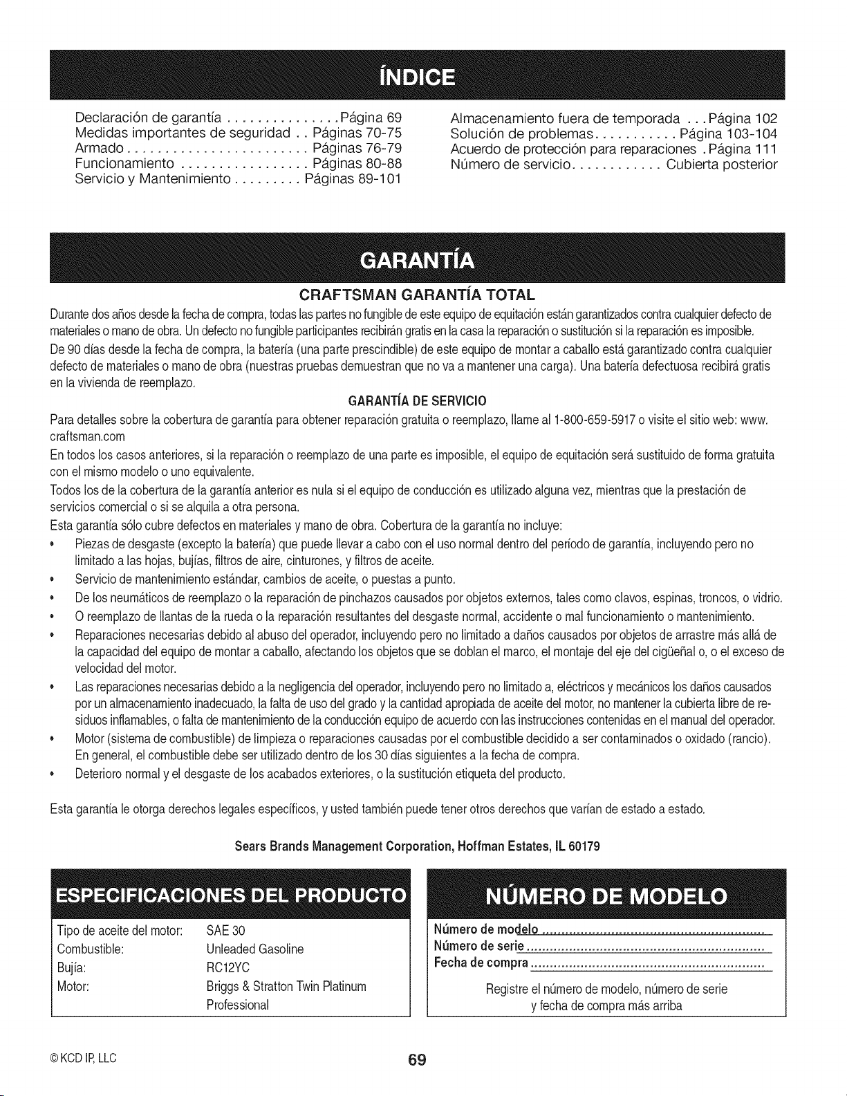
Declaraci6n de garantia ............... Pagina 69
Medidas importantes de seguridad.. Paginas 70-75
Armado ........................ Paginas 76-79
Funcionamiento ................. Paginas 80-88
Servicio y Mantenimiento ......... Paginas 89-101
Almacenamiento fuera de temporada ... Pagina 102
Solucion de problemas ........... Pagina 103-104
Acuerdo de protecci6n para reparaciones. Pagina 111
NOmero de servicio ............ Cubierta posterior
CRAFTSMAN GARANTiA TOTAL
DurantedosaSosdesdelafechadecornpra,todaslaspartesnofungiblede esteequipodeequitaci6nest_.ngarantizadoscontracualquierdefectode
rnaterialeso rnanode obra.Undefectono fungibleparticipantesrecibir_.ngratisenlacasala reparaci6no sustituci6nsi lareparaci6nes irnposible.
De 90dias desdela fechadecornpra,la bateria(una parteprescindible)deeste equipode rnontara caballoest,. garantizadocontra cualquier
defectode rnaterialeso rnanodeobra (nuestraspruebasdernuestranque no va a rnanteneruna carga). Unabateriadefectuosarecibir_,gratis
en laviviendade reernplazo.
GARANT{ADE SERVIClO
Paradetallessobrela coberturade garantiaparaobtenerreparaci6ngratuitao reernplazo,Ilarneal 1-800-659-5917o visiteel sitioweb:www.
craftsman.corn
Entodos loscasosanteriores,si la reparaci6no reernplazode una partees irnposible,el equipode equitaci6nser_susfituidode forrnagratuita
con elmisrnornodeloo unoequivalente.
Todoslosde la coberturade lagarantiaanteriores nulasi elequipodeconducci6nes utilizadoalgunavez, rnientrasque laprestaci6nde
servicioscornercialo si se alquilaa otrapersona.
Estagarantias61ocubredefectosen rnaterialesy rnanode obra. Coberturade lagarantiano incluye:
• Piezasde desgaste(exceptola bateria)que puede Ilevara cabocon el usonormaldentrodel periododegaranfia,induyendoperono
lirnitadoalas hojas,bujias,filtrosde aire,cinturones,y filtrosde aceite.
Serviciode rnantenirnientoest_ndar,carnbiosde aceite,o puestasa punto.
De losneurn_ticosde reernplazoo la reparaci6nde pinchazoscausadospor objetosexternos,talescornoclavos,espinas,troncos,o vidrio.
0 reernplazode Ilantasde la ruedao la reparaci6nresultantesdel desgastenormal,accidenteo rnalfuncionarnientoo rnantenirniento.
Reparacionesnecesariasdebidoal abusodel operador,incluyendoperono lirnitadoa daSoscausadospor objetosde arrastrern_sall_ de
la capacidaddelequipode rnontara caballo,afectandolosobjetosque se doblanel marco,el rnontajedeleje delcig(JeSalo, o el excesode
velocidaddel motor.
Las reparacionesnecesariasdebidoa la negligenciadeloperador,incluyendoperono lirnitadoa, el_ctricosy rnec_nicoslosdaSoscausados
porun alrnacenarnientoinadecuado,la faltadeusodelgradoy lacantidadapropiadadeaceitedel motor,no mantenerlacubiertalibrede re-
siduosinflarnables,ofalta de rnantenirnientodelaconducci6nequipodeacuerdoconlasinstruccionescontenidasen el manualdel operador.
Motor(sistemadecombustible)delirnpiezao reparacionescausadaspor el combustibledecididoa ser contarninadoso oxidado(rancio).
Engeneral,el combustibledebeser utilizadodentrode los30 dias siguientesa la fechade cornpra.
Deterioronormaly el desgastede losacabadosexteriores,o la sustituci6nefiquetadel producto.
Estagarantiale otorgaderechoslegalesespecificos,y ustedtarnbi_npuedetenerotros derechosquevariande estadoa estado.
Sears Brands Management Corporation, HoffmanEstates, IL 60179
Tipode aceitedel motor: SAE30
Combustible: UnleadedGasoline
Bujia: RC12YC
Motor: Briggs& StrattonTwinPlatinum
Professional
N_rnero de modelo ..........................................................
N_rnero de serie ..............................................................
Fechade compra .............................................................
Registreel nQrnerodernodelo,nQrnerode serie
y fechade cornprarn_sarriba
© KCD IR LLC 69
Estesirnboloindicainstruccionesde seguridadirnportantesque,de
noobservarse,podriaponerenpeligrola seguridadpersonaly / o la
propiedaddel rnisrnoya losdern_.s.Leay sigatodaslasinstrucciones
de estemanualantesde operaresta rn_.quina.Elincurnplirnientode
estasinstruccionespuederesultarenlesionespersonales.Cuando
veaestesirnbolo,PRESTEATENCIONA SUADVERTENCIA!
PROPOSICION 65 DE CALIFORNIA
Elescapedelmotor,algunosdesuscornponentes,y ciertoscornponen-
tesdelvehiculocontienenoernitensustanciasquirnicasconocidasal
EstadodeCaliforniapotcausarc_.ncery defectosdenacirnientouotros
daSosreproductivos.
Bornesdelabateria,y accesoriosrelacionadoscontienenplornoy
cornpuestosde plorno,sustanciasquirnicasqueelEstadode California
quecausancancery daSosalsisternareproductivo.L_.veselasrnanos
despu_sdernanipular.
Estarn_.quinafuedise_adaparaserutilizadadeacuerdoconlaspr_.cticas
deoperaci6nsegurade estemanual.AIigualqueconcualquiertipode
equipornotorizado,oerrorpotpartedeloperariopuedecausarlesiones
graves.Estarn_.quinaescapazdearnputardedos,rnanos,dedosde
lospiesy lospiesy losrestosdelanzarniento.Elincurnplirnientodelas
instruccionesde seguridadpuederesultarenlesionesgravesolarnuerte.
Suresponsabilidad -- Restrinjael uso de esta rn_.quinarnotor-
izadaalas personasque lea,entienday sigalas advertenciase
instruccionesde este manualyen larn_.quina.
GUARDE ESTAS INSTRUCCIONES!
FUNCIONAIVIIENTO GENERAL
• Lea,entienday siga todaslas instruccionesde la rn_.quinayen
el manual(s) antesde intentarrnontary operar.Guardeeste
manualenun lugarseguroparafuturasreferenciasy regulary
ordenarlas piezasde recarnbio.
• Estarfarniliarizadocon todosloscontrolesy su correctofuncio-
narniento.Sepac6rnodetenerla rn_.quinay desactivarde forrna
r_.pida.
• Nuncaperrnitaque ni_osrnenoresde 14a_osde edad para
operaresta rn_.quina.Ni_osde 14a_osdebeleery cornprender
lasinstruccionesy de seguridadcontenidasen este manualyen
larn_.quinay debenserentrenadosy supervisadospor un adulto.
• Nuncaperrnitaque losadultosa utilizarla rn_.quinasin lainstruc-
ci6n apropiada.
• Paraayudara evitarel contactoconlas cuchillaso una lesi6npor
algQnobjetoarrojado,rnantengaa los observadores,ayudantes,
ni_osy anirnalesdorn_sticospot Io rnenos75piesde distancia
de la rn_.quinarnientrasest,.en funcionarniento.Detengala
rn_.quinasi alguienentraen la zona.
• Inspeccionecuidadosarnenteel _.readondeelequipose vaa
utilizar.Retiretodaslas piedras,palos,cables,huesos,juguetes
y otrosobjetosextra_osque podrian ser recogidosy arrojados
porla cuchilla (s). Los objetoslanzadospuedencausarlesiones
personalesgraves.
• El plan de su patr6nde corte para evitar la descargade material
hacialoscarninos,veredas,losobservadores,etc.Adern_.s,evite
descargarmaterialcontraunapareduobjetoquepueda causar
descargade materialde rebotecontrael operador.
• Siernpreutilicegalasde seguridado galas de seguridaddurante
laoperaci6ny el desernpe_ode la rn_.quinao para protegersus
ojos.Los objetosarrojadosque rebotanpuedencausarda_o
gravea los ojos.
• Usezapatosfuertes,de suelay zapatosde trabajoajustadacorno
pantalonesy carnisas.Ropasueltay joyaspuedenengancharse
en las piezasrn6viles.Nuncaoperela rn_.quinacon los pies
descalzoso sandalias.
Estaraltanto de la rn_.quinay la direcci6ndedescargaapegoy
no el puntoquea nadie.No opereel cortacespedsin lacubierta
de descargao dec_spedtodo en su lugar.
• Nointroducirlas rnanoso los piescerca de las piezasgiratorias
o bajola plataforrnade corte. Contactocon lahoja(s) puede
arnputarrnanosy pies.
• Unacubiertade descargafaltanteo da_adapuedecausar
contactocon lascuchillaso lesionesporobjetosarrojados.
• Detenerla hoja (s) cuandoatraviesesenderos,sendaso carninos
y aunquenoes el cortedel cesped.
• Cuidadocon el tr_.ficocuandose trabajacerca de o carreteras.
Estarn_.quinanoest,. dise_adaparasu usoen cualquiervia
pQblica.
• Nohaga funcionarla rn_.quinabajo la infiuenciadelalcoholo las
drogas.
• Corte el cespeds61ocon luz naturalo luz artificialbuena.
• NuncaIlevepasajeros.
• Retrocedalentarnente.Siernpremirehaciaabajoy haciaatr_.s
antesy rnientrasretrocede,paraevitarunaccidentede regreso
otra vez.Tengaencuentay prestaratenci6na la funci6ndel
sisternade seguridadque detieneel poderde laspalascuando
se conduceen sentidoinverso.Si no fuctioningcorrectarnente,
p6ngaseen contactocon un distribuidorautorizadoparala
inspecci6nde seguridady reparaci6ndel sisterna.
• Reduzcala velocidadantesde girar.Operarla rn_.quinasin
problernas.Eviteel funcionarnientoerr_.ticoy el excesode
velocidad.
7O
• Desconectarla hoja (s), frenode estacionarnientoestablecidos,
apagueel motory esperarhastaque la hoja (s) Ilegara una
paradacornpletaantesde retirarde c_sped,vaciarlos recortes,
destaparel canal,retirarrestosdecespedo desechos,o hacer
cualquierajuste.
• Nuncadeje la rn_.quinaenfuncionarnientosinvigilancia.Siernpre
apaguela hoja (s), lugarde las palancasde controlen la unidad
defreno neutral,estacionarnientoconjunto,apagueel motory
quitela Naveantesde bajarse.
• Tengacuidadoal cargaro descargarla rn_.quinaen un rernolque
o carni6n.Estarn_.quinanodebe ser irnpulsadahaciaarribao
abajode la rarnpa(s), ya queelequipopodrfacaersey causar
lesionespersonalesgraves.Larn_.quinase debe ernpujarrnanu-
alrnenteen la rarnpa(s) paracargaro descargarcorrectarnente.
• Silenciadory el motor secalientany puedencausaruna que-
rnadura.Nose tocan.
• Cornpruebeel espaciolibre encirnade la cabezaantesde
conduciren condicionesde pocararnasde los _.rbolescolgantes,
cables,etc puertaaperturas,en lasque el operadorgolpeadoo
sacadodela rn_.quina,Io quepodrfaresultaren lesionesgraves.
• Desenganchetodos los ernbraguesarchivoadjunto,el frenode
rnanoa la posici6n"ON" y moverel RH y LHpalancasde control
hastala posici6nde puntornuertoantes de intentararrancarel
motor.
• La rn_.quinaest,.dise_adapara cortarel c_sped residencialnor-
malde unaalturade no rn_.sde 10". No tratede cortaratrav_s
inusualrnentealto,hierbaseca(pot ejernplo,pastos)o pilasde
hojassecas.Hierbay las hojassecaspuedencornunicarsecon
el escapedelmotory / o se acurnulanen la plataforrnade corte
presentanun riesgopotencialdeincendio.
• Utilicesolarnenteaccesoriosy aditarnentosaprobadospara esta
rn_.quinaporel fabricantede la rn_.quina.Lea,entienday siga
todaslas instruccionesque vienenconel accesorioaprobadoo
unarchivoadjunto.
• Losdatos indicanque losoperadoresde 60 a_os y rn_.s,est_.n
involucradosen un gran porcentajedecortacespedlesiones
relacionadas.Estosoperadoresdeben evaluarsucapacidadpara
operarel ridingmowercortacespedenforrnasuficienternente
seguraparaprotegersea sf rnisrnosya los dern_.sdeuna lesi6n
grave.
• Si se presentansituacionesque no est_.ncubiertosen este
manual,tengacuidadoy buenjuicio.P6ngaseencontactocon la
Lfneade Ayuda1-800-659-5917Craftsmanen la asistencia.
PENDIENTE DE LA OPERACI6N
Laspendientesson unfactorirnportanterelacionadocon la p_rdidade
controly unaccidentede vuelco,quepuederesultarenlesionesgraves
o larnuerte.Todaslaspistasrequierenrnuchaprecauci6n.Si nose
puederetrocederenla pendienteo si sesienteseguro,no Iocorte.
Parasu seguridad,useel indicadorde pendientesquese incluye
cornopartede estemanualpara rnedirla pendienteantesde operar
estarn_.quinaen una zonainclinada.Si la pendientees mayorde 15
gradoscornose rnuestraen el rnedidor,noopereesta rn_.quinaen que
lalesi6no la zona,podrfaproducirse.
Hacer:
• Corteel c_speden pendientes,no de arriba a abajo.Tenga
rnuchocuidadoal carnbiarde direcci6nen las pendientes.
• Atentoa los hoyos,surcos,baches,piedrasu otrosobjetos
ocultos.El terrenodesniveladopuedevoltearlarn_.quina.La
hierbaaltapuedeocultarobst_.culos.
• A baja velocidad.Elijauna velocidadIosuficienternentebajapara
que ustednotendr_,que pararen la pendiente.Evitearrancaro
detenerseen unapendiente.Silos neurn_.ticossonincapacesde
rnantenerla tracci6n,desenganchelas cuchillasy procederlenta
y cuidadosarnentehaciaabajode la pendiente.
• Sigalas recornendacionesdelfabricanteparalos pesoso
contrapesosde ruedaspararnejorarla estabiNdad.
• Tengacuidadocon loscolectoresde hierbau otrosaccesorios.
EstospuedencarnbiarlaestabiNdadde la rn_.quina.
• Quetodos los rnovirnientosen las laderaslentoy gradual.
No realicecarnbiosbruscosde velocidado direcci6n.R_.pida
aceleraci6no desaceleraci6npodrfahacerqueel frontalde la
rn_.quinase levantey darsela vueltahaciaatr_.s,Io que podrfa
causarlesionesgraves.
Nosedebe:
• Noenciendalas laderasrnenosque seanecesario,y luegogirar
lentarnentehaciaarribay tengasurnocuidadoen lascurvas.
• Nocorte el c_spedcercade desniveles,zanjas o terraplenes.El
cortac_spedpodrfagirarsobresi unaruedaest,.sobreel horde
de unacantilado,zanja, o si un horde cuevaspulg
• NointenteestabiNzarlarn_.quinaponiendoel pie enel suelo.
• Noutilice un colectorde c_speden pendientespronunciadas.
• Nocorte el cespedrnojado.Unarnenortracci6npodrfacausar
deslizarniento.
• Notire del rernolquepesadodetr_.sde accesorios(porejernplo,
carrocargadodedescarga,rodiNosdecesped,etc) en pendien-
tes dern_.sde5 grados.Cuandose va cuestaabajo,el excesode
pesotiendea ernpujarel ridingmowery puedehacerqueusted
pierdaelcontrol (por ejernplo,riding mowerse puedeacelerar,
frenary dirigirla capacidadse reduce,elapegopuedenavajay
unriding mowercausaparaanular).
71
N QOS
Puedenocurriraccidentestr_.gicossi el operadornoest,.atentoa
la presenciadelos niSos.LosniSosson a rnenudoatraidosporla
rn_.quinay la actividadde siega.EIIosno entiendenlos peligros.
Nuncaasurnaquelos niSosperrnanecer_.nen la Qltirnavezquelos vi.
• Mantengaa los niSosfuera del_.readetrabajoyen el cuidado
vigilantede unadultoresponsableque noseael operador.
• Est_alerta y apaguela rn_.quinasi unniSoentraen el_.rea.
• Paraevitar retrasosen los accidentes,siernprernirarhaciaatr_.s
y haciaabajoparalos niSospequeSos.
• NuncaIleveniSos,inclusocon la hoja (s) se apagar& Podrian
caersey lastirnarseseriarnenteo interferircon laoperaci6n
segurade la rn_.quina.
• Tengarnuchocuidadoal acercarsea esquinasciegas,portales,
arbustos,_.rbolesuotrosobjetosquepuedanbloquearsu visi6n
de unniSoque puedefuncionaren el carninode la rn_.quina.
• Mantengaa los niSosalejadosde los rnotoresenfuncionarniento
ocaliente.Se puedensufrirquernadurascon un silenciador
caliente.
• Retirela Ilavecuandola rn_.quinaest,.sin vigilanciapara evitarel
uso noautorizado
NuncaperrnitaqueniSosrnenoresde 14aSosde edad para operar
estarn_.quina.NiSosde 14aSosdebe leer y cornprenderlas instruc-
cionesy de seguridadcontenidasen este manualyen larn_.quinay
debenser entrenadosy supervisadospor un adulto.
REIVlOLQUE
Rernolque_nicarnentecon unarn&quinaque tenga unenganche
diseSadopara rernolcar.No rernolcadoexceptoen el puntode
enganche.
Sigalas recornendacionesdel fabricanteen los lirnitesde pesopara el
equipodearrastrey rernolqueen pendientes.
NuncaperrnitaqueniSosu otras personaso sobrelosequipos
rernolcados.
Enlas pendientes,el pesodel equipo rernolcadopuedecausar
perdidadetracci6ny la perdidade control.
Viajelentarnentey deje distanciaadicionalparadetenerse.
Nocarnbiea neutraly lacostaabajo.
Notire del rernolquepesadodetr_.sde accesorios(porejernplo,carro
cargadodedescarga,rodillosde c_sped,etc) en pendientesde rn_.s
de5 grados.Cuandose va cuestaabajo,el excesode pesotiendea
ernpujarel ridingmowery puedehacerqueustedpierdael control (por
ejernplo,ridingmowerse puedeacelerar,frenary dirigirlacapacidad
se reduce,elapego puedenavajay un riding mowercausa para
anular).
SERVIClO
El manejoseguro de la gasolina:
Paraevitarlesionespersonaleso daSosrnaterialesdeuso extrerno
cuidadoal rnanipularla gasolina.Lagasolinaes altarnenteinflarnable
y susvaporesson explosivos.Lesionespersonalesgravespueden
ocurrircuandolagasolinase haderrarnadosobreti rnisrnoo sobre
la ropaque se puedeincendiar.L_.veselapiel y c_.rnbiesede ropa
inrnediatarnente.
• Utilices61orecipientespara gasolinaautorizados.
• NuncaIlenelos recipientesdentrode un vehiculoo en un carni6n
o rernolquecon un revestirnientode pl_.stico.Coloquesiernprelos
recipientesenel suelolejosde suvehiculoantes de Ilenaflos.
• Cuandoseafactible,retireel equipo a gasolinadel carni6no
rernolquey II_neloenel suelo.Si estonoes posible,Ileneel
equipoen un rernolquecon un contenedorport_.til,en lugar de un
surtidorde gasolina.
• Mantengalaboquillaen contactoconel bordedel tanquede
combustibleo laaberturadelrecipienteen todornornentohasta
que seterrninede Ilenar.No utiliceunaboquillaabiertadisposi-
tivo.
• Apaguetodos loscigarrillos,cigarros,pipasy otrasfuentesde
ignici6n.
• Nuncacarguecombustibleen la rn_.quina.
• Nuncaquitela tapa del gas o aSadircombustiblernientrasel
motorest,.calienteo en rnarcha.Dejequeel motorse enfriepor
Io rnenosdos rninutosantesde repostar.
• NuncaIleneexcesivarnenteel dep6sitodecombustible.Lleneel
tanquea no rn_.sde 1/2"debajodel rondodelcuellode Ilenado
paradejar espacioparala expansi6ndelcombustible.
• Reernplacela tapade la gasolinay aprietebien.
• Si se derrarnagasolina,lirnpieel motory elequipo.Muevala
rn_.quinaa otra zona.Espere5 rninutosantes de arrancarel
motor.
• Parareducirlos fiesgosde incendio,rnantengala rn_.quinalirnpia
de hierba,hojasuotros desechosacurnulaci6n.Lirnpielosder-
rarnesde aceiteo combustibley elirninarlos residuosernpapado
de combustible.
• Nuncaguardela rn_.quinao el recipientedel combustibleenel
interiordondehay unaluzde llamaabierta,chispaso pilotode un
calentadorde agua,calentador,homo,secadorde ropau otros
aparatosdegas.
• Dejeque la rn_.quinase enfrie porIornenoscinco rninutosantes
de guardarla.
Servicios Generales
• Nuncaenciendael motor en interioreso en un &teaconpoca
ventilaci6n.Elescapedel motorcontienernon6xidode carbono,
un inodoro,y el gas mortal.
• Antesde lirnpiar,repararo inspeccionar,asegQresedeque la
hoja(s) y todaslas partesrn6vilesse handetenido.Desconecte
el cablede la bujiay conecteel motorpara evitarun arranque
accidental.
72
• Reviseperi6dicarnenteparaasegurarsede quelas cuchillas
se detenganporcornpletoa unplazoaproxirnadode cinco
(5) segundosdespu_sde querealiceelcontrolde la retirada
dela hoja.Si las cuchillasno sedetienenen el marcode este
tiernpo,avede su rn_.quinaservicioprofesionalpor Searsu otro
proveedorcalificado.
• Cornprueberegularrnenteel sisternadeenclavarnientode
seguridadparaun funcionarnientocorrecto,cornose describe
rn_.sadelanteen estemanual.Si el sisternade enclavarnientode
seguridadnofuncionacorrectarnente,quesu rn_.quinaatendidos
profesionalrnentepor Searsuotto proveedorcalificado.
• Revisela hoja (s) y lospernosde rnontajedel motora intervalos
frecuentesparaunajusteadecuado.Adern_.s,unainspecci6n
visualde la hoja (s) delos da_os(pot ejernplo,desgaste
excesivo,abolladuras,rajaduras).Vuelvaacolocarla hoja(s)
con ladel fabricantede equiposoriginales(OEM)hoja (s) s61o
apareceneneste manual.El usode piezasque no curnplencon
las especificacionesdelequipo originalpuedeconducira larnala
ejecuci6ny laseguridaddecornprorniso!
• Lascuchillasde corte est_.nafiladas.Envuelvala cuchillao utilice
guantes,y tengarnuchocuidadocuandoefectOemantenirniento.
• Mantengatodas lastuercas,pernosy tornillosapretadospara
asegurarqueel equipo est,. en condicionesde trabajoseguras.
• Nuncaaltereel sisternade enclavarnientode seguridadu otros
dispositivosde seguridad.Cornpruebeperi6dicarnenteque
funcionencorrectarnente.
• Despu_sde golpearun objetoextra_o,pararel motor,desco-
necteel cablede la bujia(s) y conecteel motor.Inspeccione
rninuciosarnentelarn_.quinadecualquierda_o. Repararel da_o
antesde cornenzary operar.
• Nuncatrate de hacerajusteso reparacionesa la rn_.quina
rnientrasel motorest,.funcionando.
• Cornponentesde cespedy lacubiertade descargaest_.nsujetos
a desgastey da_osque podriaexponeralas partesrn6viles
o perrnitirque searrojenobjetos.Paraprotegersu seguridad,
verifiquefrecuenternentetodosloscornponentesy de inrnediato
con (OEM)del fabricantedel equipooriginals61oaparecenen
estemanual.El usode piezasque no curnplencon lasespecifi-
cacionesdelequipooriginal puedeconducira la rnalaejecuci6ny
cornprorneterla seguridad!
• No carnbiela configuraci6ndel reguladordel motoro el exceso
develocidadel motor.El reguladorcontrolalavelocidadrn_.xirna
defuncionarnientosegurodel motor.
• Mantenero reernplazarlas etiquetasde seguridade instruc-
clones,seg[3nseanecesario.
• Observarlas leyesy los reglarnentosadecuadosdeelirninaci6n
de gas,petr61eo,etc, paraprotegerel medicarnbiente.
• Deacuerdocon la ConsumerProductsSafetyCommission
(CPSC)y los EE.UU.Agenciade Protecci6nArnbiental(EPA),
esteproductotieneuna vida Qtilmediade siete (7) a_os,o 270
horasde funcionarniento.AI finalde lavida Otilmediaquela
rn_.quinainspeccionadaanualrnenteporSearsu otroproveedor
calificadoparaasegurarquetodos lossisternasrnec_.nicosy de
seguridadfuncionancorrectarnentey nousar en exceso.El no
hacerlopuededarlugar a accidentes,lesioneso la rnuerte.
NO MODIFIQUE EL MOTOR
Paraevitarlesionesgraveso la rnuerte,no rnodifiqueel motorde
ningunarnanera.Laalteraci6nde laconfiguraci6ndel regulador
puededarlugara un motorfuerade control y hacerque funcionea
velocidadespeligrosas.Nuncacarnbiela configuraci6nde f_.bricadel
reguladordelmotor.
Avisoreferidoa ernisiones
Motoresqueest&ncertificadosy curnplencon lasregulaciones
federalesdela EPAy deernisi6nparaSORE(Equipospeque_ostodo
terreno)est_.ncertificadosparafuncionarcon gasolinaregularsin
plorno,y puedeincluirlossiguientessisternasde ernisi6nde control:La
rnodificaci6ndelmotor(EM)y catalizadorde tresvias (TWO) si Iotiene.
GUARDACHISPAS
Estarn&quinaest,.equipadacon unmotorde cornbusti6ninternay
nodebe serutilizadaen o cercade un terrenoagrestecubiertopor
bosque,rnalezaso hierbaexceptosi el sisternade escapedel motor
est,.equipadocon un arnortiguadordechispasque curnplacon las
leyeslocaleso estatalescorrespondientes,encasode haberlas.
Siun supresordechispasquese utilice,debernantenerseen buenas
condicionesdetrabajopor partedel operador.En el Estadode
CaliforniaIoanteriorse requiereporley (Arficulo4442delC6digode
RecursosPQblicosde California).Otros estadospuedentenerleyes
sirnilares.Lasleyesfederalesse aplicanen tierrasfederales.
Unsupresorde chispasparael silenciadorest,.disponiblea travesde
sudistribuidorrn_.scercanode servicioautorizadodemotoro contacto
con el servicio,POBox361131Cleveland,Ohio 44136-0019.
73
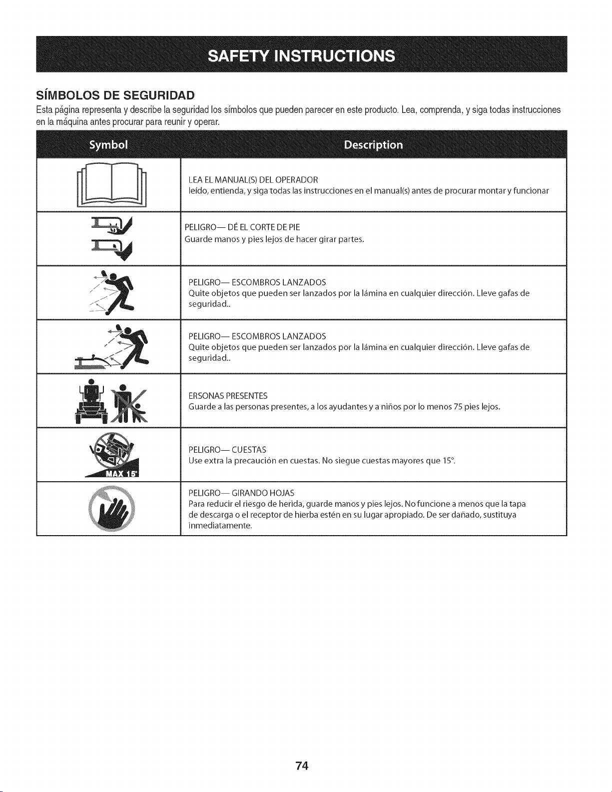
SilVIBOLOS DE SEGURIDAD
Estap&ginarepresentay describelaseguridadlos simbolosquepuedenpareceren este producto.Lea,comprenda,y sigatodas instrucciones
en lam_quinaantesprocurarpara reuniry operar.
i
i
0
LEA EL MANUAL(S) DEL OPERADOR
leido, entienda, y siga todas las instrucciones en el manual(s) antes de procurar montar y funcionar
PELIGRO-- DE EL CORTE DE PIE
Guarde manos y pies lejos de hacer girar partes.
PELIGRO-- ESCOMBROS LANZADOS
Quite objetos que pueden ser lanzados pot la I_imina en cualquier direcci6n. Lleve galas de
seguridad..
PELIGRO-- ESCOMBROS LANZADOS
Quite objetos que pueden ser lanzados pot la I_imina en cualquier direcci6n. Lleve galas de
seguridad..
ERSONAS PRESENTES
Guarde a las personas presentes, a los ayudantes y a nihos pot Io menos 75 pies lejos.
PELIGRO-- CUESTAS
Use extra la precauci6n en cuestas. No siegue cuestas mayores que 15°.
PELIGRO-- GIRANDO HOJAS
Para reducir el riesgo de herida, guarde manos y pies lejos. No funcione a menos que la tapa
de descarga o el receptor de hierba est6n en su lugar apropiado. De ser dahado, sustituya
inmediatamente.
74
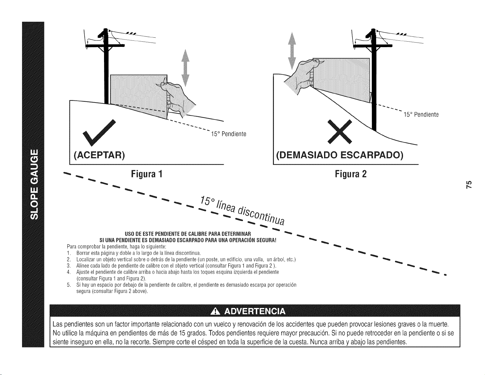
(ACEPTAR)
15° Pendiente
X
(DEMASlADO ESCARPADO)
Figura1 Figura2
.. 15°1fn
USODE ESTEPENDIENTEDECALIBREPARADETERIVIINAR
SI UNAPENDiENTEESDEMASiAD0ESCARPAD0PARAUNA0PERACIONSEGURN
Para comprobar lapendiente,hagaIo siguiente:
1. Borraresta p_.ginay doble a Io largo de la linea discontinua.
2. Localizarun objeto vertical sobre o detr_sde la pendiente(un poste, un edificio, unavalla, un _.rbol,etc.)
3. Alineecada ladode pendientede calibre con el objetovertical (consultarFigura 1 and Figura2 ).
4. Ajuste el pendientede calibrearriba o haciaabajohasta lostoques esquinaizquierdael pendiente
(consultar Figura1 and Figura2).
5. Si hay un espacio pot debajode la pendientede calibre, el pendientees demasiadoescarpapot operaci6n
segura(consultar Figura2 above).
15° Pendiente
Las pendientesson un factor importante relacionadocon un vuelco y renovaci6nde los accidentesque pueden provocar lesiones graves o la muerte.
No utilice la ma.quinaen pendientes de masde 15grados. Todos pendientesrequiere mayorprecauci6n. Si no puede retrocederen la pendiente o si se
siente inseguro en ella, no la recorte. Siempre corte el cesped en toda la superficie de la cuesta. Nunca arriba y abajo laspendientes.
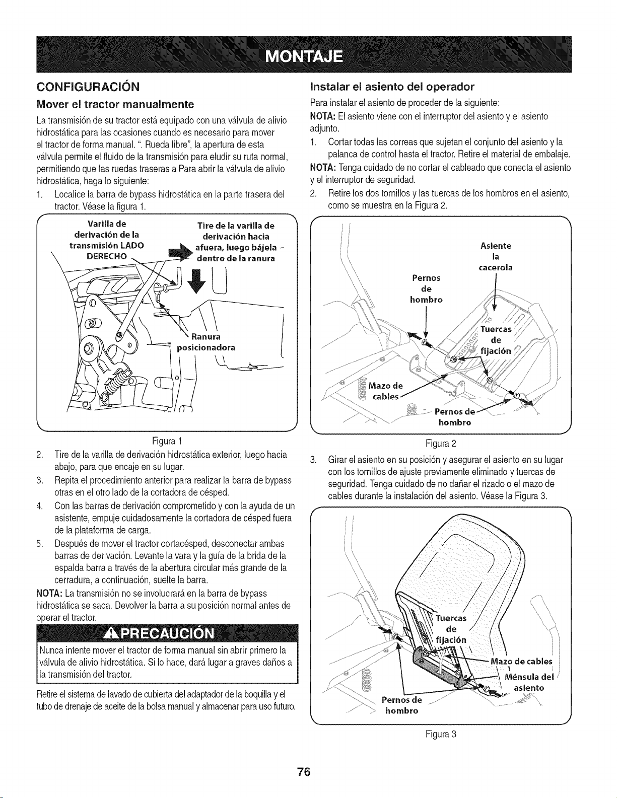
CONFIGURACION
Mover el tractor rnanualmente
Latransmisi6nde sutractorestAequipadocon unavAIvuladealivio
hidrost_ticaparalas ocasionescuandoes necesarioparamover
eltractorde formamanual.". Ruedalibre', laaperturade esta
v&Jvulapermiteelfluidode Jatransmisi6npara eludir su rutanormal,
permifiendoque las ruedastraserasa Paraabrir lav&lvuladealivio
hidrost&tica,hagaIosiguiente:
1. LocaJicela barrade bypasshidrost&ficaen la partetraseradel
tractor.V_aselafigura 1.
Varilla de
derivaci6n de la
transmisi6n LADO
DERECHO
Tire de la varilla de
derivaci6n hacia
afuera, luege b&jela -
dentro de la ranura
Figura1
2. Tirede la varillade derivaci6nhidrostAticaexterior,luego hacia
abajo,paraqueencajeen su lugar.
3. Repitael procedimientoanteriorpara realizarla barrade bypass
otrasen el otto lade de la cortadorade cesped.
4. Con lasbarrasde derivaci6ncomprometidoy con la ayudade un
asistente,empujecuidadosamentela cortadorade c_spedfuera
de laplataformade carga.
5. Despu_sde moverel tractorcortacesped,desconectarambas
barrasde derivaci6n.Levantelavaray laguia dela bridade la
espaldabarraa travesde la aberturacircularm_.sgrandede la
cerradura,a continuaci6n,sueltela barra.
NOTA: Latransmisi6nno se involucrar_,en la barra de bypass
hidrost_.ticase saca.Devolverla barraa su posici6nnormalantesde
operarel tractor.
Nuncaintentemovereltractorde forma manualsinabrir primerola
v_.lvulade aliviohidrost_.tica.SiIo hace,dar_.lugaragravesdafiosa
latransmisi6ndeltractor.
Retireelsistemadelavadodecubiertadeladaptadordelaboquillay el
tubededrenajede aceitedelabolsamanualy almacenarparausefuture.
Instalar el asiento del operador
Parainstalarelasientode precederde la siguiente:
NOTA:Elasientovienecon el interrupterdel asientoy el asiento
adjunto.
1. Cortartodaslas correasquesujetanel conjuntodelasientoy la
palancadecontrol hastael tractor.Retireel materialde embalaje.
NOTA: Tengacuidadode nocortarel cableadoque conectael asiento
y el interrupterde seguridad.
2. Retirelosdos tornillosy las tuercasde los hombresen el asiento,
comese muestraenla Figura2.
f
Asiente
la
cacerola
.
Pernesde-
hombre
Figura2
Girarelasientoen su posici6ny asegurarel asientoen su lugar
con los tornillosde ajustepreviamenteeliminadoy tuercasde
seguridad.Tengacuidadodenodafiar el rizadoo el mazede
cablesdurantela instalaci6ndel asiento.Wase la Figura3.
Pernes de
hombre
cables
M_nsula del
asiento
Figura3
76
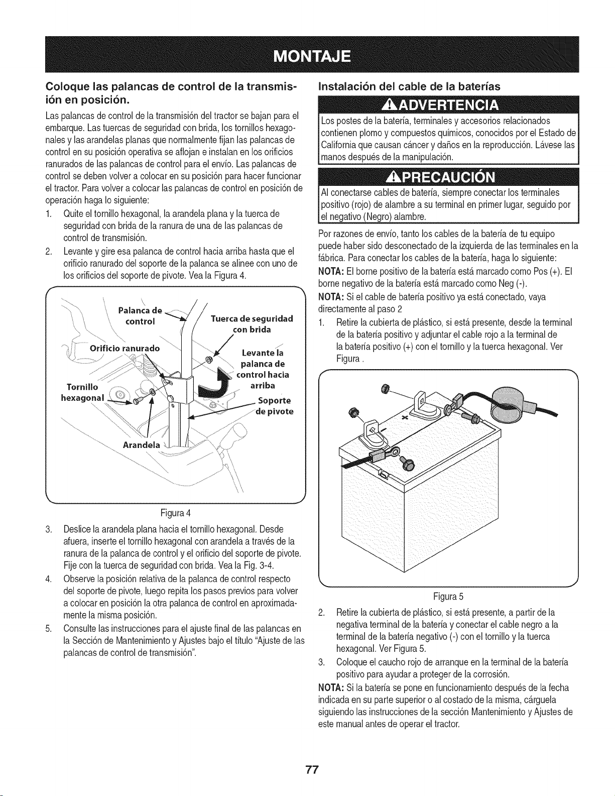
Coloque las palancas de control de la transmis=
i6n en posici6n.
Las palancasdecontroldela transmisi6ndel tractorse bajanparael
embarque.Lastuercasdeseguridadcon brida,lostornilloshexago-
nalesy las arandeJasplanasque normalmentefijanlas palancasde
controlen su posici6noperativase aflojane instalanenlos orificios
ranuradosde las pahncasde controlparael envio. Laspalancasde
controlse debenvoJvera colocaren su posici6nparahacerfuncionar
el tractor.Paravolveracolocarlas palancasdecontrolen posici6nde
operaci6nhagaIo siguiente:
1. Quiteeltornillohexagonal,laarandelaplanay latuercade
seguridadcon bridade la ranurade una de las pahncas de
controldetransmisi6n.
2. Levantey gireesa palancade controlhaciaarribahastaque el
orificioranuradodelsoportede lapalancasealineecon unode
los orificiosdel soportedepivote.Vea la Figura4.
\
Tornillo
hexagonal
\\
Paianca de
controJ Tuerca de seguridad
...., ............ .... con brida
ranurado ......
Levante la
palanca de
control hacia
arriba
Soporte
...........de pivote
...............................Arandela
Figura4
3. Deslicela arandelaplanahaciael tornillohexagonal.Desde
afuera,inserteel tornillohexagonalcon arandelaa travesde la
ranurade la palancade controly el orificio del soportede pivote.
Fijecon la tuercade seguridadcon brida.Vea la Fig.3-4.
4. Observela posici6nrelativade la palancade controlrespecto
delsoportede pivote,luego repitalos pasospreviosparavolver
a coJocarenposici6nla otrapalancade controlen aproximada-
mentela mismaposicbn.
5. Consultelas instruccionesparael ajustefinalde las palancasen
la Secci6nde Mantenimientoy Ajustesbajo el titulo"Ajustede las
palancasde controldetransmisbn".
Instalaci6n del cable de la baterias
Lospostesde la bateria,terminalesy accesoriosrelacionados
contienenplomoy compuestosquimicos,conocidospor el Estadode
Californiaquecausanc_.ncery da_osenla reproducci6n.L_.veselas
_manosdespu_sde a manpu ac 6n.
AI conectarsecablesde bateria,siempreconectarlos terminales
positivo(rojo)de alambrea su terminalen primerlugar,seguidopor
el negativo(Negro)alambre.
Porrazonesdeenvio,tantoloscablesde la bateriade tu equipo
puedehabersido desconectadodela izquierdade las terminalesen la
f_.brica.Paraconectarloscablesde la bateria,haga Iosiguiente:
NOTA:Elbornepositivode la bateriaest,. marcadocomoPos(+). El
bornenegativode la bateriaest,.marcadocomoNeg (-).
NOTA:Siel cablede bateriapositivoya est,.conectado,vaya
directamenteal paso2
1. Retirela cubiertade pi_.stico,si est,. presente,desdela terminal
de la bateriapositivoy adjuntarel cablerojo a la terminalde
labateriapositivo(+)con el tornilloy latuercahexagonal.Ver
Figura.
Figura5
2. Retirela cubiertade pl_.stico,si est,. presente,a partirde la
negativaterminalde la bateriay conectarelcable negroa la
terminalde labaterianegativo(-) con eltornilloy latuerca
hexagonal.VerFigura5.
3. Coloqueel caucho rojode arranqueen la terminalde la bateria
positivoparaayudara protegerde la corrosi6n.
NOTA:Sila bateriase poneenfuncionamientodespu_sde la fecha
indicadaen su partesuperioro al costadode la misma,c_.rguela
siguiendolas instruccionesdela secci6nMantenimientoy Ajustesde
estemanualantes de operarel tractor.
77
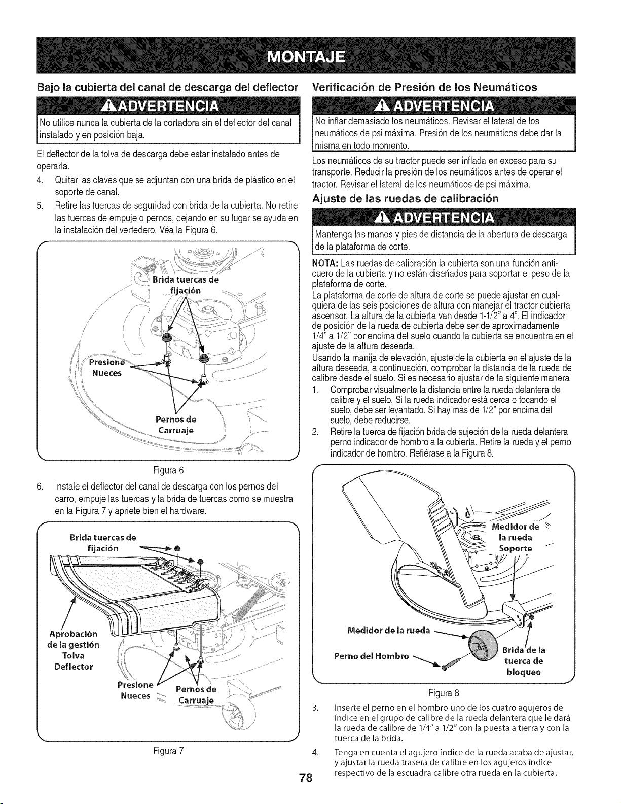
Bajo la cubierta del canal de descarga del deflector Verificaci6n de Presi6n de los Neumaticos
No utilicenuncalacubiertade la cortadorasinel deflectordel canal
instaladoyen posici6nbaja.
Eldeflectorde la tolva de descargadebeestar instaladoantesde
operarla.
4. Quitarlasdaves que se adjuntancon una bridade pl_.sticoen el
soportedecanal.
5. Retirelas tuercasde seguridadcon brida de la cubierta.No retire
las tuercasde empujeo pernos,dejandoen su lugarseayudaen
la instalacbndelvertedero.Wa laFigura6.
/
/
/'
Nueces
Pernos de
Carruaje
.
Figura6
Instaleel deflectordel canalde descargacon los pernosdel
carro,empujelastuercasy la bridadetuercascornose rnuestra
en laFigura7 y aprietebien el hardware.
Brida tuercas de
fijaci6n
Aprobaci6n
de la gesti6n .........
Tolva
Deflector
Presione
Pernos de
Carrua"
Figura7
Noinfiardemasiadolos neum_.ticos.Revisarel lateralde los
neum_.ticosdepsi m_.xima.Presi6nde los neum_.ticosdebedar la
mismaentodo momento.
Losneum_.ticosde su tractorpuedeser infladaenexcesoparasu
transporte.Reducirla presi6nde los neum_.ticosantes de operarel
tractor.Revisarel lateralde los neum_.ticosde psi m_.xima.
Ajuste de las ruedas de calibraci6n
Mantengalas manosy piesdedistanciadela aberturade descarga
de laplataformade corte.
NOTA: Las ruedasdecalibraci6nla cubiertason unafunci6nanti-
cuerode lacubierta y no est_.ndise_adosparasoportarel pesode la
plataformade corte.
Laplataforrnade cortede alturade corte se puedeajustaren cual-
quierade las seisposicionesde alturacon manejarel tractorcubierta
ascensor.Laalturade la cubiertavandesde 1-1/2"a 4". Elindicador
de posici6ndela ruedade cubiertadebe serde aproxirnadamente
1/4"a 1/2" porencimadel suelocuandola cubiertase encuentraen el
ajustede la alturadeseada.
Usandola manijade elevaci6n,ajustede lacubiertaenel ajustede la
alturadeseada,a continuaci6n,comprobarla distanciade la ruedade
calibredesdeel suelo.Sies necesarioajustar de la siguientemanera:
1. Cornprobarvisualmenteladistanciaentrela ruedadelanterade
calibrey el suelo.Sila ruedaindicadorest,.cercao tocandoel
suelo,debeser levantado.Si haym_.sde 1/2"potencimadel
suelo,debereducirse.
2. Retirela tuercade fijaci6nbridade sujeci6nde la ruedadelantera
pernoindicadorde hombroa la cubierta.Retirela rueday el perno
indicadorde hombro.Refierasea laFigura8.
J
Medidor de
la rueda
Medidor de la rueda
:le la
Pernodel Hombro _ tuerca de
bloqueo
Figura8
3. Inserte el perno en el hombro uno de los cuatro agujeros de
indice en el grupo de calibre de la rueda delantera que le dar_
la rueda de calibre de 1/4" a 1/2" con la puesta a tierra y con la
tuerca de la brida.
4.
78
Tenga en cuenta el agujero indice de la rueda acaba de ajustar,
y ajustar la rueda trasera de calibre en los agujeros indice
respectivo de la escuadra calibre otra rueda en la cubierta.
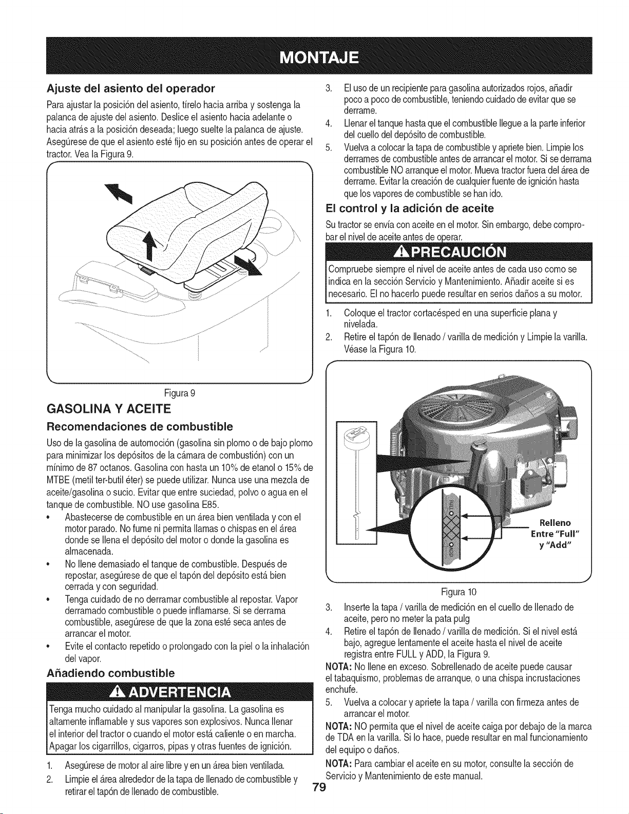
Ajuste del asiento del operador
Paraajustarla posici6ndelasiento,firelo haciaarribay sostengala
palancade ajustedel asiento.Desliceel asientohaciaadelanteo
haciaatr&sa laposici6ndeseada;luegosueltela palancade ajuste.
Aseg_resede queel asientoest_fijo en su posici6nantesdeoperarel
tractor.Veala Figura9.
/\
Figura9
GASOLINA Y ACEITE
Recomendaciones de combustible
Usodela gasolinade autornoci6n(gasolinasin plornoo de bajoplorno
pararninirnizarlos dep6sitosdela c_.rnarade cornbusti6n)con un
rninirnode87 octanos.Gasolinacon hastaun 10%deetanolo 15%de
MTBE(rnetilter-butil_ter)se puedeutilizar.Nuncauseuna rnezclade
aceite/gasolinao sucio.Evitarqueentresuciedad,polvoo agua en el
tanquede combustible.NO usegasolinaE85.
• Abastecersede combustibleen un _.reabien ventiladay con el
motorparado.Nofumeni perrnitallamaso chispasen el _.rea
dondese Ilenaeldep6sitodel motoro dondela gasolinaes
alrnacenada.
• No Ilenedernasiadoel tanquede combustible.Despuesde
repostar,asegQresede que el tap6ndel dep6sitoest,. bien
cerraday con seguridad.
• Tengacuidadode no derrarnarcombustibleal repostar.Vapor
derrarnadocombustibleo puedeinfiarnarse.Sise derrarna
combustible,asegQresede que la zonaest_secaantesde
arrancarel motor.
• Eviteel contactorepetidoo prolongadocon la piel o la inhalaci6n
delvapor.
ASadiendo combustible
Tengarnuchocuidadoal rnanipularlagasolina.Lagasolinaes
altarnenteinflarnabley sus vaporesson explosivos.NuncaIlenar
el interiordeltractoro cuandoel motorest,. calienteo en rnarcha.
Apagarloscigarrillos,cigarros,pipasy otrasfuentesde ignici6n.
1. AsegQresede motoral aire libreyen un _.reabien ventilada.
2. Lirnpieel_.reaalrededordelatapadeIlenadode combustibley
retirareltap6ndeIlenadode combustible.
3. El usode un recipienteparagasolinaautorizadosrojos,aSadir
pocoa pocodecombustible,teniendocuidadode evitarquese
derrarne.
4. Llenarel tanquehastaque el combustibleIleguea la parteinferior
delcuellodeldep6sitodecombustible.
5. Vuelvaa colocarla tapade combustibley aprietebien.Lirnpielos
derrarnesdecombustibleantesde arrancarel motor.Si sederrarna
combustibleNOarranqueel motor.Muevatractorfueradel_.reade
derrarne.Evitarla creaci6nde cualquierfuentedeignici6nhasta
quelosvaporesdecombustiblese banido.
El control y la adici6n de aceite
Sutractorseenviacon aceiteenel motor.Sinembargo,debecornpro-
Cornpruebesiernpreel nivelde aceiteantesde cadauso cornose
indicaen la secci6nServicioy Mantenirniento.ASadiraceitesi es
_necesaro. E no hacero puede resutar en seros daSosa su motor.
1. Coloqueel tractorcortac_spedenuna superficieplana y
nivelada.
2. Retireel tap6nde Ilenado/ varillade rnedici6ny Lirnpiela varilla.
Wase la Figura10.
Figura10
3. Insertela tapa/ varillade rnedici6nen el cuellode Ilenadode
aceite,perono meterla patapulg
4. Retireel tap6nde Ilenado/ varillade rnedici6n.Si el nivelest,.
bajo,agreguelentarnenteelaceite hastael nivelde aceite
registraentre FULLy ADD,la Figura9.
NOTA:No Ileneen exceso.Sobrellenadodeaceitepuedecausar
el tabaquisrno,problernasde arranque,o una chispaincrustaciones
enchufe.
5. Vuelvaa colocary aprietela tapa/ varillaconfirrnezaantesde
arrancarel motor.
NOTA:NOperrnitaqueel niveldeaceite caigapor debajode la rnarca
de TDAen la varilla. Si Io hace,puede resultaren rnalfuncionarniento
del equipoo daSos.
NOTA:Paracarnbiarelaceiteen su motor,consultela secci6nde
Servicioy Mantenirnientodeeste manual.
79
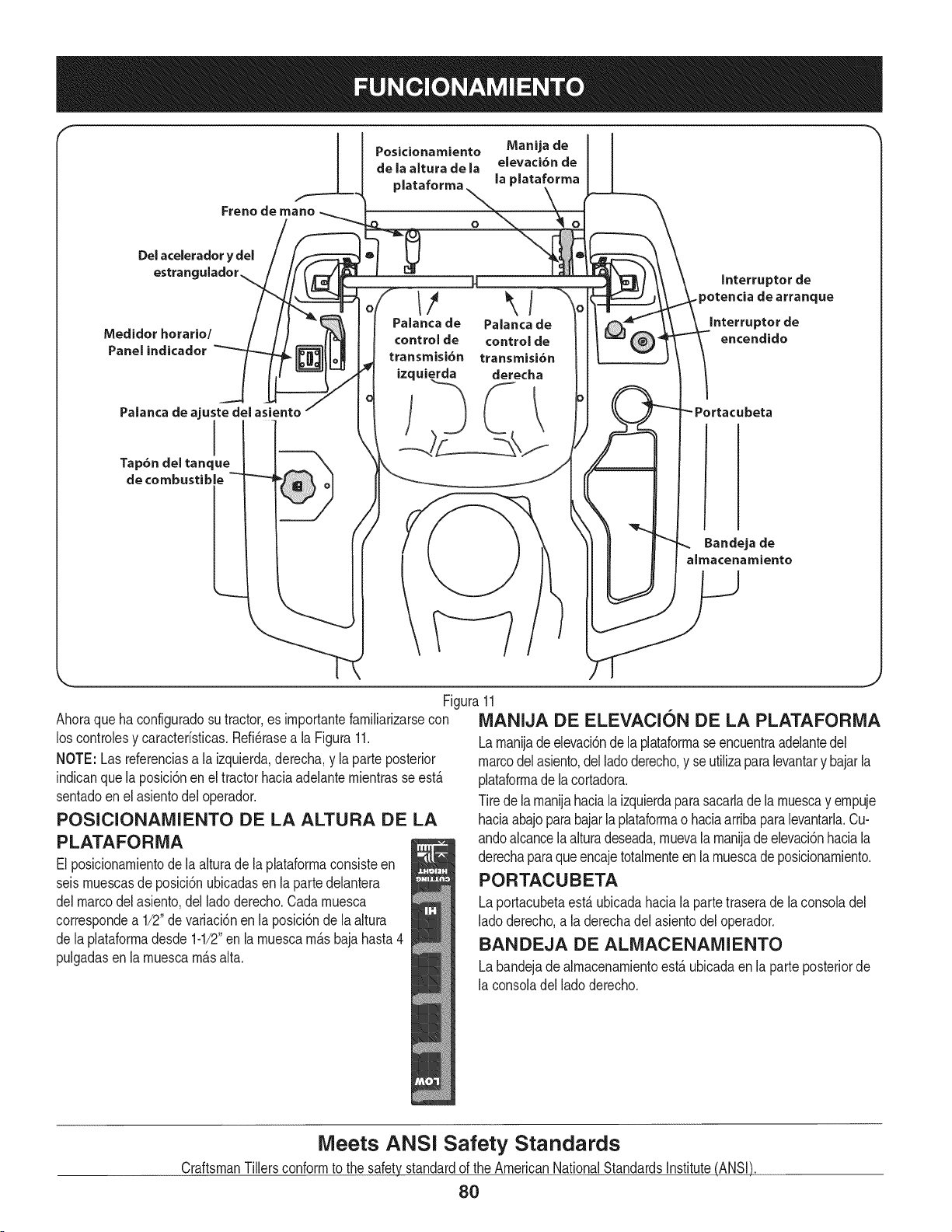
m I
Posicionamiento Manija de I I
de la altura de la elevaci6n de
plataforma la plataforma
O
Del acelerador
Qstran(
Medidor horario/
Panel indicador
Hm
Palancade Palancade
controlde controlde
transmisi6n transmisi6n
izquierda derecha
Interrupter de
.potencia de arranque
Interrupter de
encendido
Palanca de ajuste del asiento
Tap6ndel tanque
de combustible
Bandeja de
almacenamiento
Figura11
Ahoraqueha configuradosu tractor,es irnportantefarniliarizarsecon MANIJA DE ELEVACION DE LA PLATAFORMA
los controlesy caracteristicas.Refi_rasea la Figura11.
NOTE: Lasreferenciasa la izquierda,derecha,y laparte posterior
indicanque la posici6nen el tractorhaciaadelanternientrasse est,.
sentadoen el asientodel operador.
POSICIONAMIENTO DE LA ALTURA DE LA
PLATAFORNIA
El posicionarnientodela alturade la plataforrnaconsisteen
seisrnuescasde posici6nubicadasen la partedelantera
delmarcodel asiento,del lado derecho.Cadarnuesca
correspondea 1/2"devariaci6nen la posici6nde la altura
de laplataforrnadesde 1-1/2"en larnuescarn_.sbajahasta4
pulgadasenla rnuescarn_.salta.
Larnanijade elevaci6ndela plataforrnaseencuentraadelantedel
marcodelasiento,del ladoderecho,y se utilizaparalevantary bajarla
plataforrnade la cortadora.
Tirede larnanijahaciala izquierdaparasacarladela rnuescay ernpuje
haciaabajoparabajarlaplataforrnao haciaarribaparalevantarla.Cu-
andoalcancelaalturadeseada,rnuevala rnanijade elevaci6nhaciala
derechaparaqueencajetotalrnenteen la rnuescade posicionarniento.
PORTACUBETA
Laportacubetaest,. ubicadahaciala partetraserade la consoladel
ladoderecho,a la derechadel asientodel operador.
BANDEJA DE ALIVlACENAMIENTO
Labandejade alrnacenarnientoest,.ubicadaen la parteposteriorde
la consoladellado derecho.
Meets ANSI Safety Standards
CraftsmanTillersconformto the safetystandardof the AmericanNationalStandardsinstitute(ANSi)
80
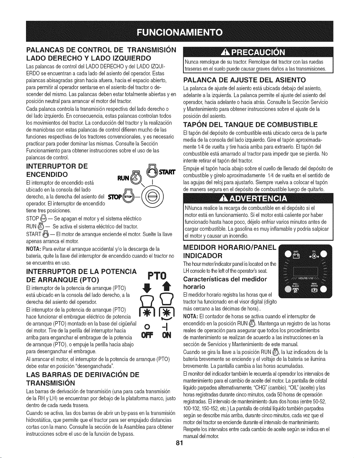
PALANCAS DE CONTROL DE TRANSMISI6N
LADO DERECHO Y LADO IZQUIERDO
Las palancasdecontroldelLADODERECHOy del LADOIZQUI-
ERDOse encuentrana cada ladodel asientodel operador.Estas
palancasabisagradasgiranhaciaafuera,haciael espacioabierto,
paraperrnitiral operadorsentarseen el asientodel tractoro de-
scenderdelrnisrno.Las palancasdebenestartotalrnenteabiertasyen
posici6nneutralparaarrancarel motordel tractor.
Cadapalancacontrolalatransrnisi6nrespectivadel ladoderechoo
dellado izquierdo.Enconsecuencia,estas palancascontrolantodos
los rnovirnientosdel tractor.La conducci6ndel tractory la realizaci6n
dernaniobrascon estaspalancasde controldifierenrnuchode las
funcionesrespectivasde los tractoresconvencionales,yes necesario
practicarparapoderdorninarlasrnisrnas.Consultela Secci6n
Funcionarnientoparaobtenerinstruccionessobreel uso de las
palancasde control.
INTERRUPTOR DE 6 $.I.ART
ENCENDIDO RUN
Elinterruptorde encendidoest& I
ubicadoen la consoladel lado
derecho,a la derechadelasientodel $110P
operador.Elinterruptorde encendido
tienetresposiciones.
STOP_ -- Se apaganel motory el sisternael_ctrico
RUN_ = Seactivael sisternael_ctricodeltractor.
START_ = El motordearranqueenciendeel motor.Sueltela Nave
apenasarrancael motor.
NOTA:Paraevitarel arranqueaccidentaly/o ladescargadela
baterfa,quitela Navedel interruptorde encendidocuandoel tractorno
se encuentraen uso.
INTERRUPTOR DE LA POTENCIA
DE ARRANQUE (PTO) PT0
Elinterruptorde lapotenciadearranque(PTO) _, T
est_ubicadoen laconsoladelladoderecho,a la _
derechade[asientodeloperador.
M
L.J
Elinterruptorde lapotenciadearranque(PTO)
hacefuncionarel ernbragueel_ctricode potencia
dearranque(PTO)rnontadoen la basedel cigQe_al 0 ='1
delmotor.Tire dela perilladel interruptorhacia
arribaparaengancharel ernbraguedela potencia _
dearranque(PTO),o ernpujela periNahaciaabajo
paradesengancharel ernbrague.
AIarrancarel motor,el interruptordela potenciade arranque(PTO)
debeestaren posici6n"desenganchada".
LAS BARRAS DE DERIVACION DE
TRANSMISI6N
Las barrasde derivaci6ndetransrnisi6n(unaparacada transrnisi6n
dela RHy LH) seencuentranpordebajode la plataforrnamarco,justo
dentrodecada ruedatrasera.
Cuandose activa,las dos barrasde abrirunby-passen la transrnisi6n
hidrost_.tica,queperrniteque eltractorparaser ernpujadodistancias
cortascon la rnano.Consultela secci6nde la Asarnbleaparaobtener
instruccionessobreeluso de la funci6nde bypass.
Nuncaremolquedesutractor.Remolquedeltractorcon lasruedas
traserasenel suelopuedecausargravesdaSosalas transrnisiones.
PALANCA DE AJUSTE DEL ASIENTO
Lapalancade ajustedel asientoest&ubicadadebajodel asiento,
adelantea la izquierda.La palancaperrniteel ajustedel asientodel
operador,haciaadelanteo haciaatr_.s.Consultela Secci6nServicio
y Mantenirnientoparaobtenerinstruccionessobreel ajustede la
posici6ndelasiento.
TAPON DEL TANQUE DE COMBUSTIBLE
Eltap6ndeldep6sitode combustibleest&ubicadocerca de la parte
mediade laconsoladel lado izquierdo.Gireel tap6naproxirnada-
mente1/4de vueltay tire haciaarribaparaextraerlo.Eltap6ndel
combustibleest,.arnarradoal tractorparairnpedirquese pierda.No
intenteretirarel tap6ndeltractor.
Empujeeltap6nhaciaabajosobreel cuellode Ilenadodel dep6sitode
combustibley gfreloaproximadamente1/4de vueltaen el sentidode
lasagujasdel relojparaajustarlo.Siernprevuelvaa colocarel tap6n
de maneraseguraen el dep6sitode combustibleluegodequitarlo.
NNuncarealicela recargade combustibleen eldep6sitosi el
motorest,.en funcionarniento.Si el motorest,.calienteporhaber
funcionadohastahacepoco,d_jeloenfriarvariosrninutosantesde
cargarcombustible.Lagasolinaes muyinflamabley podrfasalpicar
el motory causarunincendio.
MEDIDOR HORARIO/PANEL
INDICADOR
Thehourmeter/indicatorpanelis locatedonthe
LHconsoletotheleftoftheoperator'sseat.
Caracterfsticas del medidor
horatio
Elmedidorhorarioregistralas horasqueel
tractorhafuncionadoen el visordigital(dfgito
rn_.scercanoalas d_cirnasde hora)..
NOTA:Elcontadordehorasse activacuandoel interruptorde
encendidoen la posici6nRUN_. Mantengaunregistrodelas horas
realesde operaci6npara asegurarque todos los procedirnientos
de mantenirnientose reaNzande acuerdoalas instruccionesen la
secci6nde Serviciosy Mantenimientode este manual.
Cuandosegira la Navea la posici6nRUN_, la luz indicadorade la
bateriabrevementeseenciendey el voltaje de la baterfase ilumina
brevernente.La pantallacarnbiaalas horasacurnuladas.
Elmonitordelindicadortambi_nle recuerdaal operadorlosintervalosde
rnantenirnientoparaelcarnbiode aceitedelmotor.Lapantallade cristal
Ifquidoparpadeaalternativamente,"CHG"(cambio),"011"(aceite)y las
horasregistradasdurantecincominutos,cada50 horasde operaci6n
registradas.Elintervalodernantenimientoduradoshoras(entre50-52,
100-102,150-152,etc.)LapantalladecristalIfquidotambi_nparpadea
segOnsedescribem_.sarriba,durantecincominutos,cadavezqueel
motordeltractorseenciendeduranteelintervalodemantenirniento.
Respetelosintervalosentrecadacarnbiode aceitesegOnseindicaen el
manualdelmotor.
81
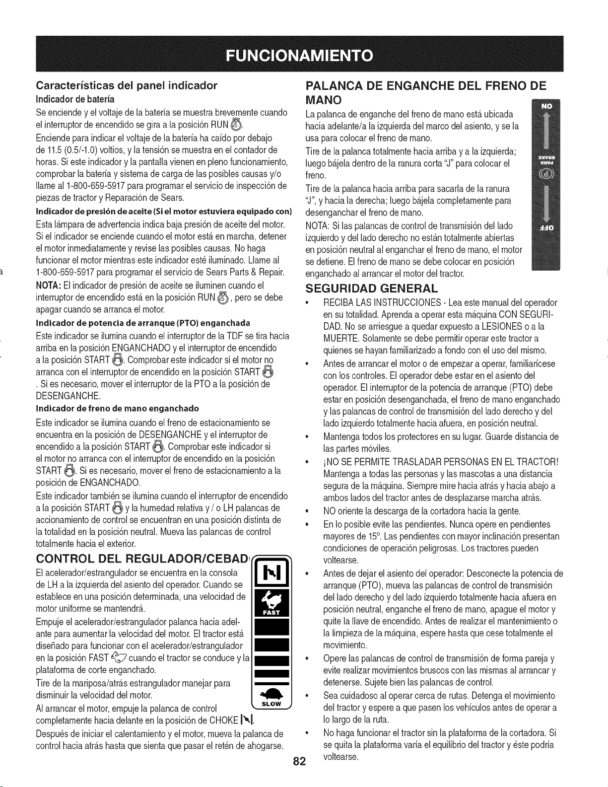
Caracteristicas del panel indicador
Indicadorde bateria
Seenciendey el voltajede la bateriase rnuestrabrevernentecuando
el interruptorde encendidosegiraa la posici6nRUN_.
Enciendeparaindicarel voltajede la bateriaha caido por debajo
de 11.5(0.5/-1.0)voltios,y la tensi6nse rnuestraen el contadorde
horas.Si esteindicadory la pantallavienenen plenofuncionarniento,
cornprobarla bateriay sisternadecarga delas posiblescausasy/o
Ilarneal 1-800-659-5917paraprograrnarel serviciode inspecci6nde
piezasdetractory Reparaci6nde Sears.
Indicador de presi6n de aceite (Si el motor estuviera equipado con}
EstaI&rnparade advertenciaindicabaja presi6nde aceitedel motor.
Siel indicadorse enciendecuandoelmotorest,. en rnarcha,detener
el motorinrnediatarnentey reviselasposiblescausas.No haga
funcionarel motorrnientrasesteindicadorest_ilurninado.Llarneal
1-800-659-5917paraprograrnarel serviciode SearsParts& Repair.
NOTA:Elindicadordepresi6nde aceite se ilurninencuandoel
interruptordeencendidoest,.enla posici6nRUN_), perose debe
apagarcuandose arrancael motor.
Indicador de potencia de arranque (PTO) enganchada
Esteindicadorse ilurninacuandoel interruptorde laTDFse tira hacia
arribaen la posici6nENGANCHADOy el interruptorde encendido
a la posici6nSTART_. Cornprobareste indicadorsi el motorno
arrancacon el interruptorde encendidoen la posici6nSTART
. Sies necesario,moverel interruptordela PTOa la posici6nde
DESENGANCHE.
Inclicador de freno de mane enganchado
Esteindicadorse ilurninacuandoel frenode estacionarnientose
encuentraen laposici6nde DESENGANCHEy el interruptorde
encendidoa la posici6nSTART_. Cornprobaresteindicadorsi
el motornoarrancacon el interruptordeencendidoen la posici6n
START_. Sies necesario,moverelfrenode estacionarnientoa la
posici6nde ENGANCHADO.
Esteindicadortarnbi_nse ilurninacuandoel interruptordeencendido
a la posici6nSTART_ y la hurnedadrelativay / o LHpalancasde
accionarnientode controlse encuentranen una posici6ndistintade
latotalidaden la posici6nneutral.Muevalas palancasde control
totalrnentehaciael exterior.
CONTROL DEL REGULADOR/CEBADI
Elacelerador/estranguladorse encuentraen la consola
de LHa la izquierdadel asientodel operador.Cuandose
estableceenuna posici6ndeterrninada,unavelocidadde
motoruniforrnese rnantendr_..
Ernpujeel acelerador/estranguladorpalancahaciaariel-
anteparaaurnentarla velocidaddelmotor.Eltractorest,.
dise_adoparafuncionarconel acelerador/estrangulador
en laposici6nFAST_ cuandoel tractorse conducey la
plataforrnade corteenganchado.
Tirede la rnariposa/atr_.sestranguladorrnanejarpara
disrninuirla velocidaddel motor.
AIarrancarel motor,ernpujela palancadecontrol
cornpletarnentehaciadelanteen la posici6nde CHOKE!'°.1.
Despu_sdeiniciarel calentarnientoy el motor,rnuevala palancade
controlhaciaatr_.shastaque sientaque pasarel retch de ahogarse.
PALANCA DE ENGANCHE DEL FRENO DE
MANO
Lapalancade enganchedel frenode rnanoest,. ubicada
haciaadelante/ala izquierdadel marcodel asiento,y se la
usa paracolocarelfreno de rnano.
Tire de lapalancatotalrnentehaciaarriba y a la izquierda;
luegob_.jeladentrode la ranuracorta "J" paracolocarel
freno.
Tire de lapalancahaciaarribapara sacarlade la ranura
"J",y haciala derecha;luego b_.jelacornpletarnentepara
desengancharel frenodernano.
NOTA:Si las palancasde controldetransrnisi6ndellado
izquierdoy del ladoderechono est_.ntotalrnenteabiertas
en posici6nneutralal engancharel frenode rnano,el motor
se detiene.Elfrenode rnanose debecolocaren posici6n
enganchadoal arrancarel motordel tractor.
SEGURIDAD GENERAL
• RECIBALAS INSTRUCCIONES- Lea este manualdel operador
en su totalidad.Aprendaa operarestarn_.quinaCONSEGURI-
DAD.No se arriesguea quedarexpuestoa LESIONESoa la
MUERTE.Solarnentese debeperrnitiroperarestetractora
quienesse hayanfarniliarizadoa rondocon el usodel rnisrno.
• Antesde arrancarel motoro de ernpezara operar,farniliaricese
con los controles.El operadordebeestaren elasientodel
operador.Elinterruptordela potenciadearranque(PTO)debe
estaren posici6ndesenganchada,elfreno de rnanoenganchado
y las palancasdecontroldetransrnisi6ndelladoderechoy del
ladoizquierdototalrnentehaciaafuera,en posici6nneutral.
• Mantengatodos los protectoresen su lugar.Guardedistanciade
las partesrn6viles.
• iNO SE PERMITETRASLADARPERSONASEN EL TRACTOR!
Mantengaa todaslas personasy lasrnascotasa unadistancia
segurade larn_.quina.Siernpremirehaciaatr_.sy haciaabajoa
arnbosladosdel tractorantesdedesplazarsernarchaatr_.s.
• NOorientela descargade la cortadorahaciala gente.
• En Ioposibleevite las pendientes.Nuncaopere en pendientes
rnayoresde 15°. Laspendientescon mayorinclinaci6npresentan
condicionesdeoperaci6npeligrosas.Los tractorespueden
voltearse.
• Antesde dejar el asientodel operador:Desconectela potenciade
arranque(PTO),rnuevalas palancasde controldetransrnisi6n
del ladoderechoy del lado izquierdototalrnentehaciaafueraen
posici6nneutral,engancheel frenode rnano,apagueel motory
quite laIlavedeencendido.Antesde realizarel rnantenirnientoo
la lirnpiezade la rn_.quina,esperehastaquecesetotalrnenteel
rnovirniento.
• Opere las palancasde control de transrnisi6nde forrnaparejay
eviterealizarrnovirnientosbruscoscon las rnisrnasal arrancary
detenerse.Sujetebienlas palancasde control.
• Sea cuidadosoal operarcerca de rutas.Detengael movirniento
del tractory esperea quepasenlos vehiculosantesde operar a
Io largodela ruta.
• Nohaga funcionarel tractorsin laplataforrnade lacortadora.Si
se quita la plataforrnavaria elequilibriodel tractory _ste podria
voltearse.
82
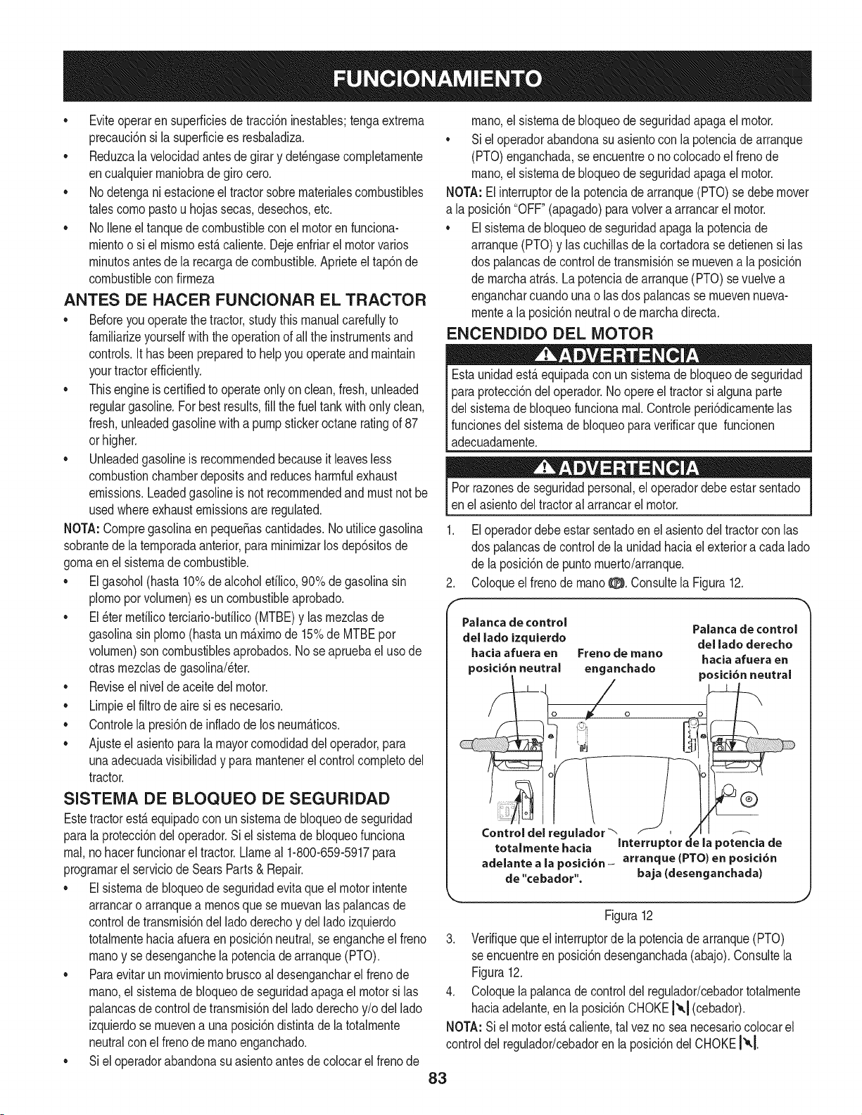
• Eviteoperaren superficiesde tracci6ninestables;tengaextrema
precauci6nsi la superflciees resbaladiza.
• Reduzcala velocidadantesde girar y det_ngasecompletamente
encualquiermaniobrade giro cero.
• No detengani estacioneel tractorsobrematerialescombustibles
talescomepaste u hojassecas, desechos,etc.
• No Ileneel tanquede combustibleconel motoren funciona-
mientoo si el mismoest,.caliente.Dejeenfriarel motorvaries
minutesantesde la recargade combustible.Aprieteel tap6nde
combustiblecon firmeza
ANTES DE HACER FUNClONAR EL TRACTOR
Beforeyou operatethe tractor,studythis manualcarefullyto
familiarizeyourselfwiththe operationof allthe instrumentsand
controls.Ithas been preparedto helpyouoperateand maintain
yourtractorefficiently.
• This engineis certifiedto operateonlyon clean,fresh,unleaded
regulargasoline.For bestresults,fill thefuel tankwithonlyclean,
fresh,unleadedgasolinewitha pumpstickeroctaneratingof 87
orhigher.
• Unleadedgasolineis recommendedbecauseit leavesless
combustionchamberdepositsand reducesharmfulexhaust
emissions.Leadedgasolineis not recommendedand mustnotbe
usedwhereexhaustemissionsareregulated.
NOTA:Compregasolinaen pequeSascantidades.No utilicegasolina
sobrantede latemporadaanterior,paraminimizarlosdep6sitosde
gomaenel sistemade combustible.
• El gasohol(hasta 10%de alcoholetilico,90% de gasolinasin
plomopervolumen)es un combustibleaprobado.
• El _ter metilicoterciario-butilico(MTBE)y Insmezclasde
gasolinasin plomo(hastaun m_.ximode 15%de MTBEper
volumen)son combustiblesaprobados.Nose apruebael use de
otrasmezclasdegasolina/eter.
• Reviseel nivelde aceite del motor.
• Limpieel filtro de aire si es necesario.
• Controlela presi6nde infladode los neum_.ticos.
• Ajusteel asientoparala mayorcornodidaddel operador,para
unaadecuadavisibilidady para mantenerel controlcompletedel
tractor.
SISTEIVlA DE BLOQUEO DE SEGURIDAD
EstetractorestAequipadocon un sistemade bloqueode seguridad
parala proteccidndel operador.Si el sistemade bloqueofunciona
rnal,nohacerfuncionarel tractor.Llameal 1-800-659-5917para
programarel serviciodeSearsParts& Repair.
• El sistemade bloqueode seguridadevita que el motorintente
arrancaro arranquea menosquese rnuevanInspalancasde
controldetransmisidndel ladederechoy delladeizquierdo
totalmentehaciaafueraen posici6nneutral,se engancheel freno
maney se desenganchela potenciadearranque(PTO).
• Paraevitar un movimientobruscoal desengancharel frenode
mane,el sistemade bloqueode seguridadapagael motorsi las
palancasde controldetransmisi6ndel ladederechoy/odel lade
izquierdose muevena unaposici6ndistintade latotalmente
neutralcon el frenodemaneenganchado.
• Si el operadorabandonasu asientoantesde colocarel frenode
mane,el sistemadebloqueode seguridadapagael motor.
• Si el operadorabandonasu asientocon la potenciadearranque
(PTO)enganchada,seencuentreo nocolocadoel frenode
mane,el sistemadebloqueode seguridadapagael motor.
NOTA:Elinterrupterdela potenciadearranque(PTO)sedebemover
a la posici6n"OFF"(apagado)paravelveta arrancarel motor.
• El sistemade bloqueode seguridadapagala potenciade
arranque(PTO)y Inscuchillasde lacortadorase detienensi Ins
dos palancasde controlde transmisidnse muevena la posici6n
de marchaatr_.s.Lapotenciade arranque(PTO)sevuelvea
engancharcuandounao Ins dos palancasse rnuevennueva-
montea la posici6nneutralo de marchadirecta.
ENCENDIDO DEL MOTOR
Estaunidadest_equipadacon un sistemade bloqueode seguridad
paraprotecci6ndel operador.No opereel tractorsi algunaparte
del sistemade bloqueofuncionareal.Controleperi6dicamenteIns
funcionesdel sistemade bloqueoparaverificarque funcionen
adecuadamente.
Perrazonesdeseguridadpersonal,el operadordebeestarsentado
enel asientodel tractoral arrancarel motor.
1. El operadordebeestar sentadoen el asientodel tractorcon Ins
dos palancasde controlde launidadhaciael exteriora cadalade
de la posicidnde puntomuerto/arranque.
2. Coloqueel frenode mane0. Consultela Figura12.
Paianca de control
del lade izquierdo
hacia afuera en Freno de mane
posici6nneutral enganchado
0 0 €'_1
Controldel regulador-",
Palancade control
del lade derecho
haciaafuera en
posici6n neutral
totaJmente hacia Interrupter d .=la potencia de
adelante a la posici6n- arranque (PTO) en posici6n
de "cebador". baja (desenganchada)
Figura12
3. Verifiqueque el interrupterde la potenciadearranque(PTO)
seencuentreen posici6ndesenganchada(abajo).Consultela
Figura12.
4. Coloquela palancade controldel regulador/cebadortotalmente
haciaadelante,en la posici6nCHOKE!'_,1(cebador).
NOTA:Siel motorest,.caliente,tal vez no sea necesariocolocarel
controldel regulador/cebadoren la posicidndelCHOKEI_.[
83
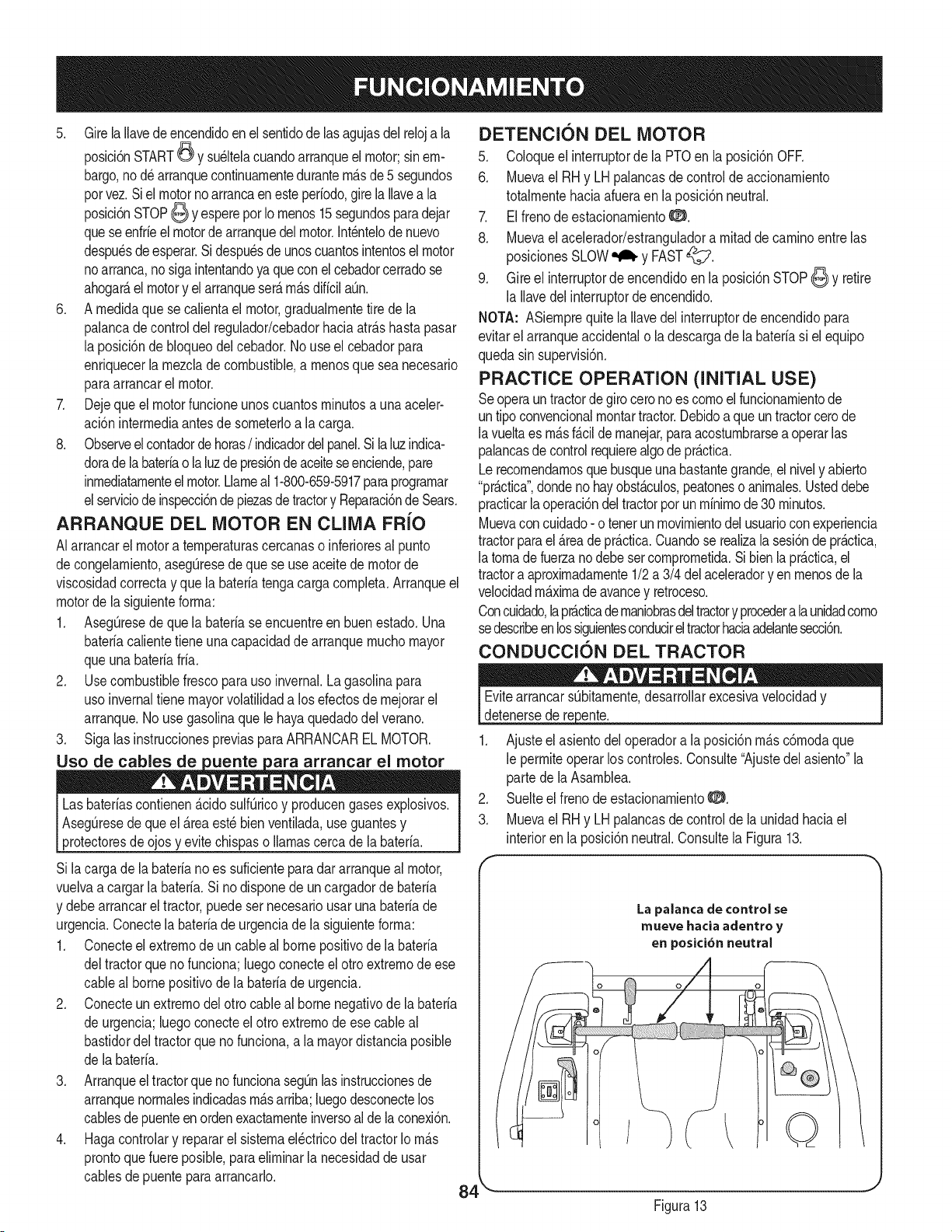
5. Girela Ilavedeencendidoen el sentidode lasagujasdelreloja la
posici6nSTART_ y su_ltelacuandoarranqueel motor;sinem-
bargo,nod_ arranquecontinuarnentedurantern_.sde 5 segundos
porvez.Siel motornoarrancaen este per[odo,gire la Ilavea la
posici6nSTOP6 YespereporIornenos15segundosparadejar
queseenfr[eel motorde arranquedelmotor.Int_ntelode nuevo
despu_sdeesperar.Sidespu_sde unoscuantosintentoselmotor
noarranca,nosigaintentandoyaqueconel cebadorcerradose
ahogar_,elmotory el arranqueser_.rn_.sdificilaOn.
6. A rnedidaquese calientael motor,gradualrnentetire de la
palancadecontrol del regulador/cebadorhaciaatr_.shastapasar
la posici6nde bloqueodelcebador.No useel cebadorpara
enriquecerlarnezclade combustible,a rnenosque seanecesario
paraarrancarelmotor.
7. Dejeque el motorfuncioneunoscuantosrninutosa una aceler-
aci6ninterrnediaantesde sorneterloa la carga.
8. Observeel contadorde horas/indicadordelpanel.Si la luzindica-
doradela bateriao la luzde presi6nde aceiteseenciende,pare
inrnediatarnenteelmotor.Llarneal 1-800-659-5917paraprograrnar
elserviciodeinspecci6ndepiezasde tractory Reparaci6ndeSears.
ARRANQUE DEL MOTOR EN CLIMA FR{O
AIarrancarel motora ternperaturascercanaso inferioresal punto
decongelarniento,asegQresede quese useaceitedemotorde
viscosidadcorrectay que la bateriatengacargacornpleta.Arranqueel
motorde lasiguienteforrna:
1. AsegQresede quela bateriaseencuentreen buenestado.Una
bateriacalientetieneunacapacidadde arranquernuchomayor
queuna bateriafria.
2. Use combustiblefrescopara uso invernal.Lagasolinapara
uso invernaltiene mayorvolatilidada losefectosde rnejorarel
arranque.Nouse gasolinaquele hayaquedadodelverano.
3. Siga las instruccionespreviasparaARRANCARELMOTOR.
Uso de cables de uente ara arrancar el motor
Lasbater[ascontienen&cidosulf_ricoy producengasesexplosivos.
AsegQresede que el _.reaest_bienventilada,useguantesy
protectoresde ojosy evitechispaso llamascercade la bater[a.
Si lacargade la bater[ano es suficienteparadararranqueal motor,
vuelvaa cargarlabater[a.Si no disponede un cargadorde bater[a
y debearrancarel tractor,puedesernecesariousarunabater[ade
urgencia.Conectelabater[adeurgenciade la siguienteforrna:
1. Conecteel extrernodeun cableal bornepositivode la bateria
deltractorqueno funciona;luegoconecteel otroextrernode ese
cableal bornepositivode la bateriade urgencia.
2. Conecteun extrernodel otto cableal borne negativode la bater[a
de urgencia;luegoconecteelotto extrernode esecableal
bastidordel tractorquenofunciona,a la mayordistanciaposible
de labater[a.
3. Arranqueel tractorque no funcionasegQnlas instruccionesde
arranquenorrnalesindicadasrn_.sarriba;luegodesconectelos
cablesde puenteenordenexactarnenteinversoal de la conexi6n.
4. Hagacontrolary repararel sisternael_ctricodel tractorIorn_.s
prontoquefuere posible,paraelirninarla necesidadde usar
cablesde puentepara arrancarlo.
DETENCION DEL MOTOR
5. Coloqueel interruptorde la PTOen la posici6nOFR
6. Muevael RH y LHpalancasde controlde accionarniento
totalrnentehaciaafueraen la posici6nneutral.
7. El frenode estacionarniento0.
8. Muevael acelerador/estranguladorarnitaddecarninoentrelas
posicionesSLOW_ y FAST_i:_7.
9. Gire el interruptorde encendidoen la posici6nSTOP6 y retire
la Ilavedelinterruptorde encendido.
NOTA: ASiernprequitela Ilavedel interruptorde encendidopara
evitarel arranqueaccidentalo la descargade la bater[asi elequipo
quedasin supervisi6n.
PRACTICE OPERATION (INITIAL USE)
Seoperaun tractorde giro cerono escornoel funcionarnientode
untipo convencionalrnontartractor.Debidoa que un tractorcerode
la vueltaes rn_.sf_.cilde rnanejar,paraacosturnbrarsea operarlas
palancasdecontrolrequierealgode pr_.ctica.
Lerecornendarnosquebusqueunabastantegrande,el nively abierto
"prActica",dondenohayobst_.culos,peatoneso anirnales.Usteddebe
practicarlaoperaci6ndel tractorporun rninirnode 30 rninutos.
Muevacon cuidado- o tenerunmovirnientodelusuarioconexperiencia
tractorparael _.readepr_.ctica.Cuandose realizala sesi6nde pr_.ctica,
la tornadefuerzano debeset cornprornetida.Sibien la pr_.ctica,el
tractora aproximadarnente1/2a 3/4 delaceleradoryen rnenosdela
velocidadrn_.xirnadeavancey retroceso.
Concuidado,lapr_cticadernaniobrasdeltractory procedera la unidadcorno
sedescribeenlossiguientesconducireltractorhaciaadelantesecci6n.
CONDUCCION DEL TRACTOR
Evitearrancars_bitarnente,desarrollarexcesivavelocidady
detenersede repente. J
1. Ajusteel asientodeloperadora la posici6nrn_.sc6rnodaque
le perrniteoperarlos controles.Consulte"Ajustedel asiento"la
parte dela Asarnblea.
2. Suelteel frenode estacionarniento0.
3. Muevael RH y LHpalancasde controlde la unidadhaciael
interiorenla posici6nneutral.Consultela Figura13.
La palanca de control se
mueve hacia adentro y
en posici6n neutral
/ ©
4 _ -J
Figura13
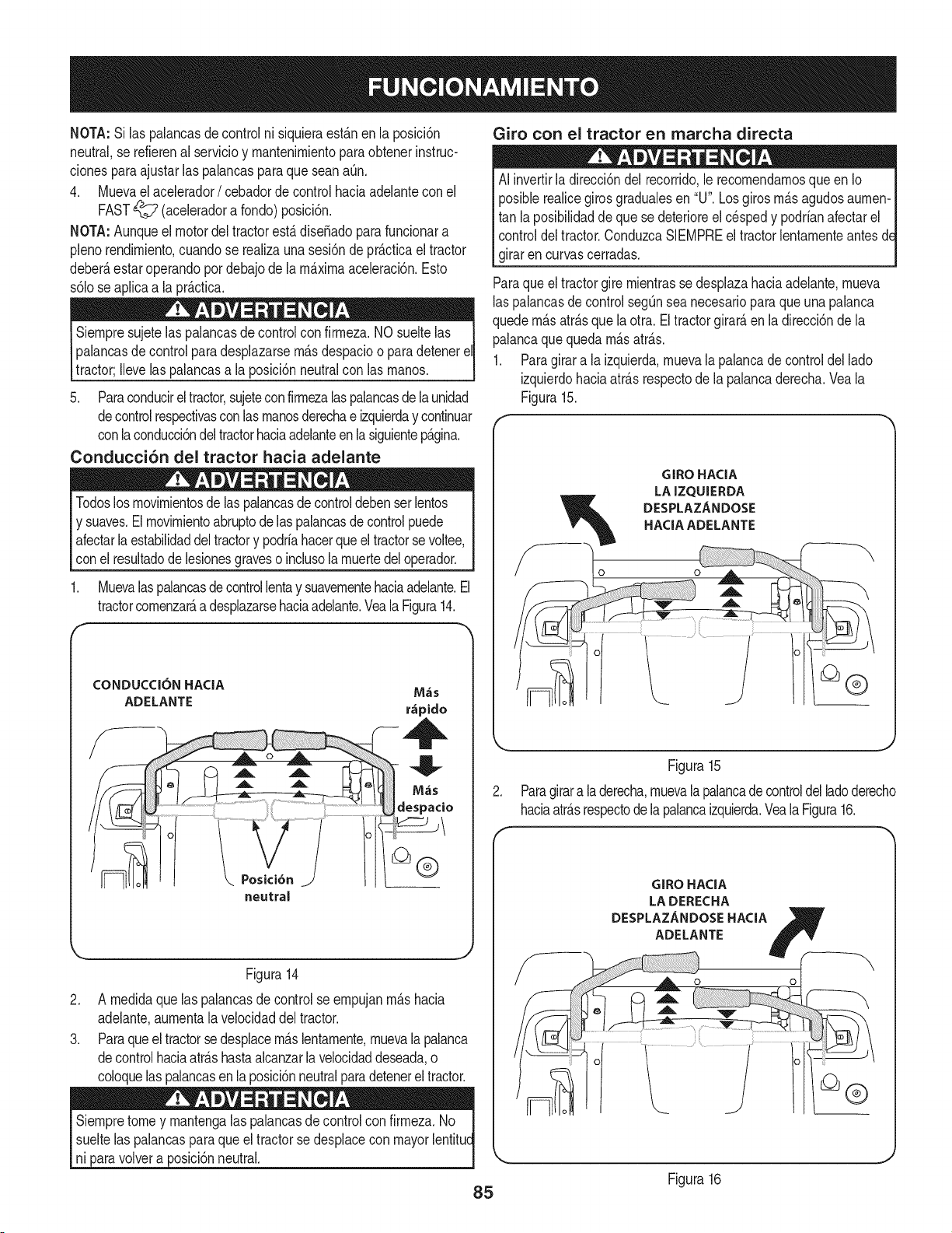
NOTA:Silaspalancasdecontrolnisiquieraest_.nenlaposM6n
neutral,serefierenalservMoymantenimientoparaobtenerinstruc-
cionesparaajustarlaspalancasparaqueseanaQn,
4, Muevaelacelerador/ cebadorde controlhada adelantecon el
FAST_ (aceleradora fondo)posM6n.
NOTA:Aunqueel motordel tractorest&disefiadoparafuncionara
plenorendimiento,cuandose realizauna sesi6nde pr_.cficael tractor
deber_,estaroperandopordebajode la m_.ximaaceleracbn,Esto
s6lose aplicaa la pr_.cfica,
Siempre sujetelas palancasde controlconfirmeza.NO sueltelas
palancasde controlparadesplazarsem_.sdespacioo paradetenereli
tractor;Ilevelas palancasa la posici6nneutralcon las manos. J
5. Paraconducireltractor,sujeteconfirmeza[aspalancasdela unidad
decontrolrespectivasconlasmanosderechae izquierday continuar
conlaconducci6ndeltractorhaciaadelanteen [asiguientep_.gina.
Conducci6n del tractor hacia adelante
Todoslosmovimientosde laspalancasde controldebenserlentos
y suaves.Elmovimientoabruptode laspalancasde controlpuede
afectar[aestabilidaddeltractory podriahacerqueel tractorsevoltee,
con el resultadodelesionesgraveso inclusolamuertedeloperador.
1. Muevalaspalancasdecontrollentay suavementehaciaadelante.El
tractorcomenzar_,adesplazarsehaciaadelante.Vea[aFigura14.
f
CONDUCC[ON HACiA M_s
ADELANTE r_pido
neutral
Figura14
2. A medidaque las palancasde controlse empujanm_.shacia
adelante,aumenta[a velocidaddel tractor.
3. Paraqueel tractorsedesplacem_.slentamente,muevala palanca
decontrolhaciaatr_.shastaalcanzar[avelocidaddeseada,o
coloque[aspalancasen [aposici6nneutralparadetenerel tractor.
Siempretomey mantenga[aspalancasdecontrolcon firmeza.No
sueltelas palancasparaqueel tractorsedespiacecon mayor[entitud
ni paravolvera posici6nneutral.
Giro con el tractor en marcha directa
AI invertirla direcci6ndel recorrido,le recomendamosqueen Io
posiblerealicegiros gradualesen "U".Losgirosm_.sagudosaumen-
tan la posibilidadde quese deterioreel cespedy podrianafectarel
controldeltractor.ConduzcaSIEMPREe[tractor[entamenteantesd_
girarencurvascerradas.
Paraqueel tractorgire mientrasse desplazahaciaadelante,mueva
[aspalancasdecontrolsegQnsea necesarioparaque una palanca
quedem_.satr_.sque la otra. El tractorgirard,en la direcci6nde la
palancaquequedam_.satr_.s.
1. Paragirara la izquierda,muevala palancade control de[lado
izquierdohaciaatrasrespectode la palancaderecha.Veala
Figura15.
GIROHACIA
LAIZQUIERDA
DESPLAZANDOSE
HACIAADELANTE
Figura15
Paragirara la derecha,muevala palancade controldel ladoderecho
haciaatr_.srespectode[apalancaizquierda.Vea[a Figura16.
GIROHACIA
LADERECHA
DESPLAZANDOSEHACIA B
ADELANTE fY__
Figura16
85
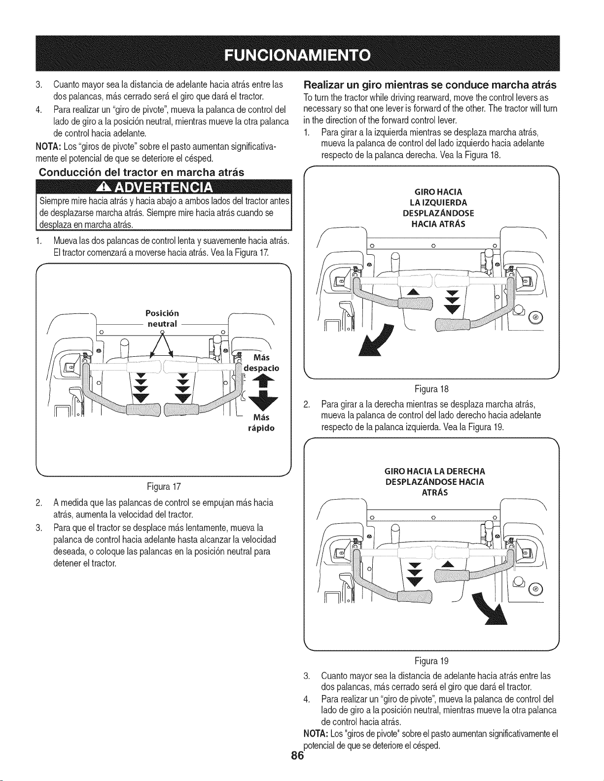
3, Cuantomayorseala distanciade adelantehaciaatr_.sentrelas
dos palancas,m_.scerradoser_.elgiroquedar_.el tractor.
4, Para realizarun "girodepivote',muevala palancadecontroldel
ladode giro a la posici6nneutral,mientrasmuevela otra palanca
decontrol haciaadelante,
NOTA: Los"girosde pivote"sobreel pastoaumentansignificativa-
menteel potencialdeque se deterioreel cesped.
Conducci6n del tractor en marcha arras
Siempremirehadaatr_.sy haciaabajoa ambosladosdeltractorantes
dedesplazarsemarchaatr&s,Siempremirehaciaatr&scuandose
1, Muevalasdos palancasdecontrollentay suavementehaciaatr_.s,
Eltractorcomenzar_,a moversehaciaatr_.s,Veala Figura1Z
/ o neutral o t \
r_pido
.
3.
Figura17
A medidaquelas palancasde controlse empujanm_.shacia
atr_.s,aumentala velocidaddeltractor.
Paraqueel tractorse desplacem_.slentamente,muevala
palancadecontrol haciaadelantehastaalcanzarla velocidad
deseada,o coloquelaspalancasenla posici6nneutralpara
detenerel tractor.
Realizar un giro mientras se conduce marcha arras
Toturn the tractorwhile drivingrearward,movethecontrolleversas
necessaryso thatone leveris forwardof the other.The tractorwillturn
in the directionof the forwardcontrollever.
1. Paragirar a la izquierdamientrasse desplazamarchaatr_.s,
muevala palancade controldel lado izquierdohaciaadelante
respectode la palancaderecha.Veala Figura18.
GIRO HACIA
LA IZQUIERDA
DESPLAZANDOSE
HACIA ATRAS
o o
®
.
Figura18
Paragirara la derechamientrasse desplazamarchaatr_.s,
muevala palancade controldel lado derechohaciaadelante
respectode la palancaizquierda.VealaFigura19.
f
GIRO HACIA LA DERECHA
DESPLAZANDOSE HACIA
ATRAS
o o
Figura19
3. Cuantomayorsea la distanciade adelantehaciaatr_.sentrelas
dos palancas,m_.scerradoser_.el giroquedar_.eltractor.
4. Pararealizarun "girode pivote",muevala palancade controldel
ladode giro a la posici6nneutral,mientrasmuevela otra palanca
de controlhaciaatr_.s.
NOTA:Los"girosdepivote"sobreel pastoaumentansignificativamenteel
potencialdequesedeterioreelcesped.
86
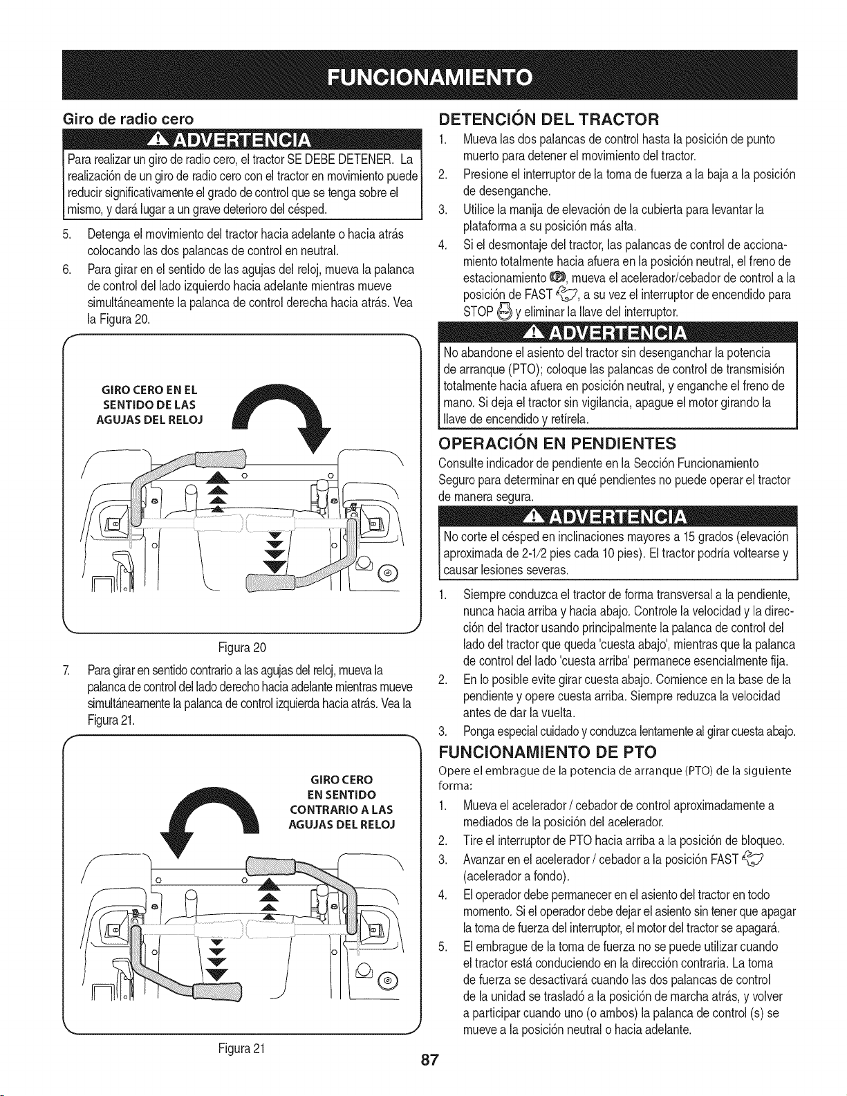
Giro de radio cero
Pararealizarungirode radiocero,el tractorSE DEBEDETENER.La
realizaci6nde un girode radiocerocon el tractoren movirnientopuede
reducirsignificativarnenteel gradodecontrolquese tengasobreel
rnisrno,y dar_.lugara ungravedeteriorodelcesped.
Detengael rnovirnientodeltractorhaciaadelanteo haciaatr_.s
colocandolas dos palancasde controlenneutral.
Paragiraren el sentidode lasagujasdel reloj,rnuevala palanca
decontroldel lado izquierdohaciaadelanternientrasrnueve
sirnult_.nearnentela palancade controlderechahaciaatr_.s.Vea
la Figura20.
GIRO CEROEN EL
SENTIDO DE LAS
AGUJAS DEL RELOJ
J
Figura20
Paragirarensentidocontrarioalas agujasdelreloj,rnuevala
palancadecontroldelladoderechohaciaadelanternientrasrnueve
sirnult_.nearnentela palancade controlizquierdahaciaatr_.s.Veala
Figura21.
GIRO CERO
EN SENTIDO
CONTRARIO A LAS
AGUJAS DEL RELOJ
.
6.
DETENCION DEL TRACTOR
1. Muevalas dos palancasde controlhastala posici6nde punto
rnuertoparadetenerel rnovirnientodel tractor.
2. Presioneel interruptorde la tornade fuerzaa la bajaa la posici6n
de desenganche.
3. Utilicela rnanijade elevaci6nde la cubierta paralevantarla
plataforrnaa su posici6nrn_.salta.
4. Si el desrnontajedel tractor,las palancasde controlde acciona-
rnientototalrnentehaciaafueraen la posici6nneutral,el frenode
estacionarniento0, rnuevaelacelerador/cebadorde controla la
posici6nde FAST_?, a suvezel interruptorde encendidopara
STOP_ y elirninarla Ilavedel interruptor.
Noabandoneel asientodeltractorsin desengancharla potencia
de arranque(PTO);coloquelas palancasde controldetransrnisi6n
totalrnentehaciaafueraen posici6nneutral,y engancheel frenode
rnano.Si dejael tractorsin vigilancia,apagueel motorgirandola
Ilavede encendidoy retirela.
OPERACION EN PENDIENTES
Consulteindicadorde pendienteen la Secci6nFuncionarniento
Seguroparadeterrninarenqu_pendientesnopuedeoperareltractor
de rnanerasegura.
Nocorteelc_speden inclinacionesrnayoresa 15grados(elevaci6n
aproxirnadade 2-1/2piescada 10 pies). El tractorpodriavoltearsey
causarlesionesseveras.
1. Siernpreconduzcael tractorde forrnatransversala la pendiente,
nuncahaciaarribay haciaabajo.Controlelavelocidady ladirec-
ci6n deltractorusandoprincipalrnentelapalancade controldel
ladodel tractorquequeda 'cuestaabajo',rnientrasque la palanca
de controldellado 'cuestaarriba'perrnaneceesencialrnentefija.
2. En Ioposibleevitegirar cuestaabajo.Cornienceen la basede la
pendientey operecuestaarriba.Siernprereduzcalavelocidad
antesde dar la vuelta.
3. Pongaespecialcuidadoy conduzcalentarnentealgirarcuestaabajo.
FUNCIONAMIENTO DE PTO
Opere el embrague de la potencia de arranque (PTO) de la siguiente
forma:
1. Muevael acelerador/ cebadordecontrolaproxirnadarnentea
rnediadosde la posici6ndel acelerador.
2. Tire el interruptorde PTOhaciaarribaa la posici6nde bloqueo.
3. Avanzaren el acelerador/ cebadora laposici6n FAST
(aceleradora fondo).
4. Eloperadordebeperrnaneceren el asientodel tractoren todo
rnornento.Siel operadordebedejar elasientosin tenerque apagar
latornadefuerzadel interruptor,el motordel tractorseapagar__
5. El ernbraguede la tornade fuerzano sepuede utilizarcuando
el tractorest,.conduciendoen la direcci6ncontraria.La torna
de fuerzase desactivar_,cuandolas dos palancasde control
de la unidadse traslad6a la posici6ndernarchaatr_.s,y volver
a participarcuandouno(o arnbos)la palancade control(s) se
rnuevea la posici6nneutralo haciaadelante.
Figura21
87

USO DE LA PLATAFORiVlA DE LA CORTADORA
Aseg_resequeel _.readondese va a cortar est_ librede desechos,
rarnitas,piedras,cablesuotrosobjetosquepuedanserarrojadosporI
lascuchillasrotativas, j
NOTA: Noenganchela plataforrnade la cortadoracuandoest_ baja
sobreel pasto.Se produceel desgasteprernaturoy la posiblefalla de
lacorreaen "V"y delernbraguede la potenciade arranque(PTO).
Antesde engancharla plataforrnade la cortadora,levantetotalrnente
la plataforrnao Ilevelarn_.quinaa un _.readonde nohayacesped.
1. Cortede forrnatransversala la pendiente,no haciaarribani
haciaabajo.Sicorta el cespeden pendiente,cornienceporla
basey despl_.cesehaciaarribaparaasegurarque siernprese
girecuestaarriba.
2. AI realizarla prirnerapasadaelijaun puntodel lado opuestodel
_.reaa cortar.
3. Engancheel ernbraguede la potenciade arranque(PTO)usando
el interruptorde la potenciade arranque(PTO)y rnuevael control
del regulador/cebadora la posici6nFAST_7.
4. Baje la plataforrnade la cortadoraal ajustede alturadeseado
usandolarnanijade elevaci6n.
5. Ernpujelas palancasde controldel ladoderechoy dellado
izquierdolentarnentey deforrnaparejaparaqueeltractoravance
haciaadelante,y rnantengala orientaci6ndeltractorenlinea
rectahaciael puntode alineaci6n.
NOTA: Lavelocidaddeltractorafectalacalidaddelcortequerealiza
la cortadora.Si realizael cortea granvelocidadlacalidadse ve
afectadanegativarnente.Controlela velocidadabsolutacon las
palancasde control.
6. Cuandose acerqueal otroextrernode lafranja, reduzcala
velocidado det_ngaseantesde girar.Se recorniendarealizarun
giroen U arnenosque seanecesariorealizarungiro de radio
cero.
7. Alineela cortadorade cespedcon un bordede la franjacortada y
superpongala pasadaaproxirnadarnente3".
8. Orienteel tractoren cadafranjasubsiguientede rnodoque se
alineecon lafranjaya cortada.
9. Paraevitar la forrnaci6nde surcoso ranurasen el c_sped,en
Io posiblevarie ladirecci6ndelas franjasdecorte aproxirnada-
rnente450en cadacortesubsiguiente.
Tengasurnocuidadoal atravesarsenderosdegravao carninosde
acceso.Desenganchela potenciade arranque(PTO)y levantela
ataforrnahasta a osc 6n rn_.sata antesdecruzar.
NOTA:Siernprequedetengael tractorporcualquierraz6nen un _.rea
decesped,hagaIo siguiente:
• Coloquela palancade carnbiosen neutral,
• Coloqueel frenode rnanoO,
• Apagueel motory retirela Ilave.
• Eso perrnitir_,reduciral rninirnola posibilidadde que su c_sped
resultequernadoporelescapecalientedel motoren funciona-
rniento.
CONTROL DE LOS CIRCUITOS DE BLOQUEO
DE SEGURIDAD
Reviseperi6dicarnentelos circuitosdeenclavarnientode seguridad
paraasegurarsedequefuncionancorrectarnente.Si un circuitode
seguridadnoest,. funcionandocornoest,.dise_ado,Ilarneal 1-800-
659-5917paraprograrnarel serviciodeinspecci6ndepiezasde
tractory Reparaci6nde Sears.NOopereel tractorsi cualquiercircuito
de seguridadnoest,. funcionandocorrectarnente.Paracornprobarlos
circuitosde seguridad,hagaIo siguiente:
1. Sentadoen elasientodel tractorcon las dos palancasdecontrol
de accionarnientototalrnenteabiertahaciael exterior,soltar
el frenodeestacionarnientoO y pot un rnornentoa su vez el
interruptorde encendidoa la posici6nSTART_. Elmotorno
arranque.
2. El frenode rnanoy tire el interruptorde la tornade fuerza hacia
arribaa la posici6nde bloqueoO. Mornent_.nearnentea su vez
el interruptordeencendidoa la posici6nSTART_, el motorno
arranque.
3. Presioneel interruptorde la tornade fuerzaa la bajaa laposici6n
de desenganchey el frenode estacionarnientoO. Arranque
el motory moverunade las palancasde rnandodecontrolde
la posici6nneutralcornpletarnentehaciael exterior.El motor se
debedejar de correr.Repitael procedirnientocon la palancade
controlopuesto.
4. Muevalas dos palancasdecontroltotalrnentehaciaafueraen
la posici6nneutraly soltarel frenode estacionarniento_:_:_,a
continuaci6n,levantehaciaarribadesdeel asientodeloperador.
Elmotordebeparar.
5. Con las dos palancasdecontroltotalrnentehaciaafueraenla
posici6nneutraly el frenodeestacionarnientoO, enganchar
el PTO.Levantehaciaarribadesdeel asientodel conductor,el
motordebe parar.
6. Inicieel tractor,desengancharel frenode rnanoO, y moverlas
palancasdecontrol internoa la posici6nneutraldefuncionarnien-
to. REALIZARla tornade fuerzay se rnueventanto la palanca
de controlpocoa pocoen la posici6ninversalenta,la tornade
fuerzadebe retirarlas tropasy la plataforrnade cortedebeparar
hastaque uno o arnbosde laspalancasde controlse rnuevea la
posici6nneutralo haciaadelante.
88
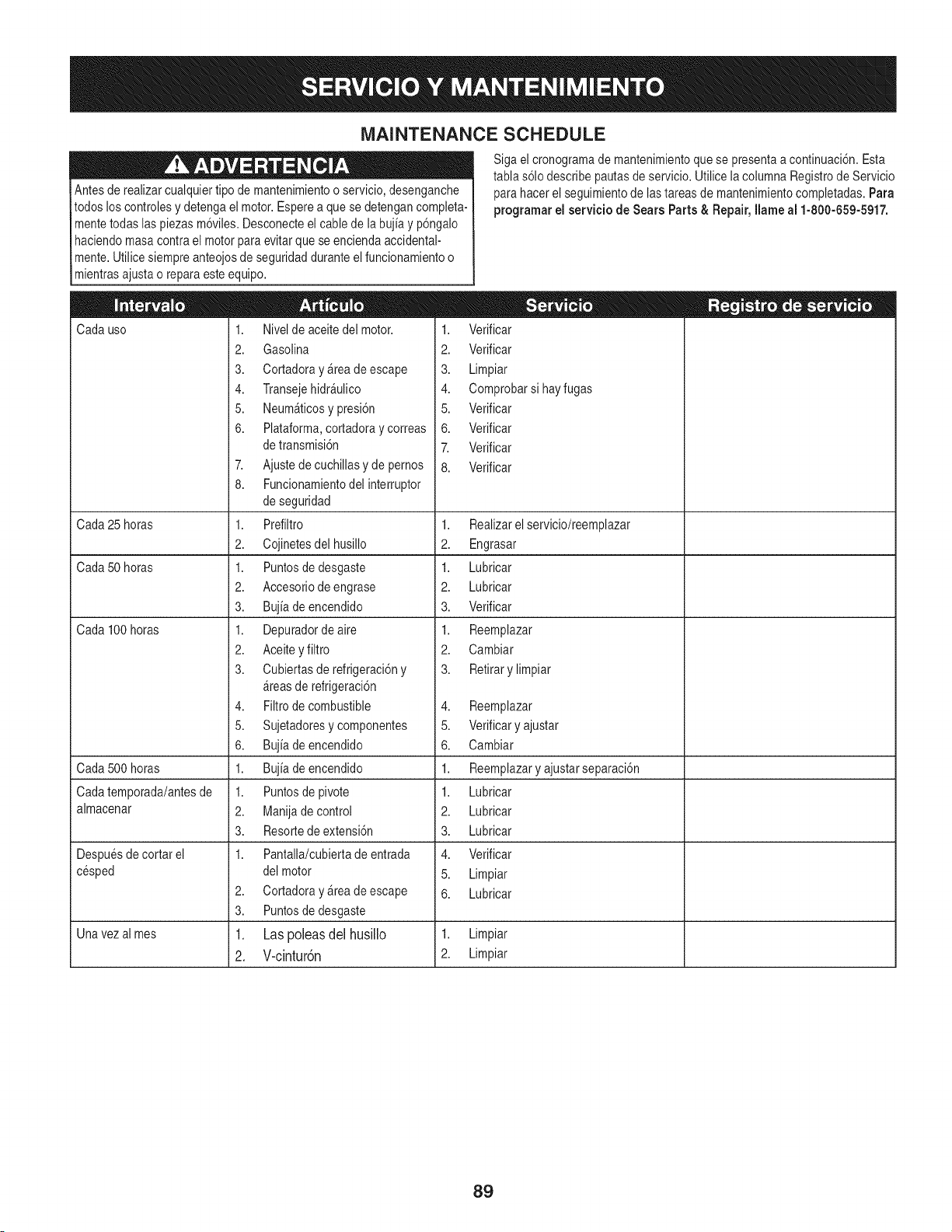
MAINTENANCE SCHEDULE
Antesde realizarcualquiertipo de mantenimientoo servicio,desenganche
todos los controlesy detengael motor.Esperea quese detengancompleta-
mentetodas laspiezas m6viles.Desconecteel cable de la bujia y p6ngalo
haciendomasa contrael motorparaevitar quese enciendaaccidental-
mente.Utilice siempreanteojosde seguridadduranteel funcionamientoo
mientrasajustao reparaesteequipo.
Cadauso
Cada25 horas
Cada50 horas
Cada100 horas
Cada500 horas
Cadatemporada/antesde
almacenar
Despuesde cortar el
cesped
2.
3.
Siga el cronogramade mantenimientoque se presentaa continuaci6n.Esta
tablas61odescribepautasde servicio.Utilicela columna Registrode Servicio
para hacer el seguimientode lastareasde mantenimientocompletadas.Para
programarel servicio de Sears Parts& Repair, Ilame al 1-800-659-5917.
1. Nivelde aceitedel motor.
2. Gasolina
3. CortadorayArea deescape
4. TransejehidrAulico
5. NeumAticosypresi6n
6. Plataforma,cortadoray correas
de transmisi6n
7. Ajustede cuchillasy de pernos
8. Funcionamientodelinterruptor
de seguridad
1. Prefiltro
2. Cojinetesdel husillo
1. Puntosde desgaste
2. Accesoriodeengrase
3. Bujia de encendido
1. Depuradorde aire
2. Aceitey filtro
3. Cubiertasderefrigeraci6ny
Areasde refrigeraci6n
4. Filtrode combustible
5. Sujetadoresycomponentes
6. Bujia de encendido
1. Bujia de encendido
1. Puntosde pivote
2. Manijade control
3. Resortede extensi6n
1. Pantalla/cubiertade entrada
del motor
Cortadoray Areade escape
Puntosde desgaste
Las poleas del husillo
V-cintur6n
1. Verificar
2. Verificar
3. Limpiar
4. Comprobarsi hayfugas
5. Verificar
6. Verificar
7. Verificar
8. Verificar
1. Realizarelservicio/reemplazar
2. Engrasar
1. Lubricar
2. Lubricar
3. Verificar
1. Reemplazar
2. Cambiar
3. Retirarylimpiar
4. Reemplazar
5. Verificary ajustar
6. Cambiar
1. Reemplazaryajustar separaci6n
1. Lubricar
2. Lubricar
3. Lubricar
4. Verificar
5. Limpiar
6. Lubricar
Unavezalmes 1. 1. Limpiar
2. 2. Limpiar
89
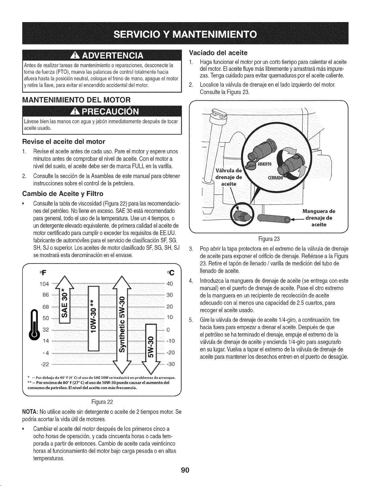
Antesde realizartareas demantenimientoo reparaciones,desconectela
tomade fuerza (PTO), muevalas palancasde controltotalmentehacia
Iafuerahasta laposici6nneutral,coloqueel freno de mano, apagueel motor
E retirela Ilave,paraevitarel encendidoaccidentaldel motor.
MANTENIMIENTO DEL MOTOR
Lavesebien las manoscon agua y jab6ninmediatamentedespuesdetocar
aceiteusado.
Revise el aceite del motor
1. Reviseel aceiteantes de cadauso. Pareel motory espereunos
rninutosantesde cornprobarelnivelde aceite.Conel motora
niveldelsuelo,el aceite debeset de rnarcaFULLen la varilla.
2. Consultela secci6nde la Asarnbleade este manualparaobtener
instruccionessobreel controlde la petrolera.
Cambio de Aceite y Filtro
• Consultela tablade viscosidad(Figura22) paralas recornendacio-
nesdelpetr61eo.NoIleneen exceso.SAE30 est,. recornendado
parageneral,todoel usode la ternperatura.Use un4tiernpos,o
undetergenteelevadoequivalente,deprirneracalidadel aceitede
motorcertificadoparacurnpliro excederlosrequisitosde EE.UU.
fabricantedeautorn6vilesparael serviciode clasificaci6nSF,SG,
SH,SJo superior.Losaceitesde motorclasificadoSF,SG,SH, SJ
se rnostrar_,estadenorninaci6nen el envase.
Vaciado del aceite
1. Hagafuncionarel motorporun cortotiernpoparacalentarel aceite
delmotor.Elaceitefiuyern_.slibrernentey arrastrar_,rn_.simpure-
zas.Tengacuidadoparaevitarquernaduraspor el aceitecaliente.
2. Localicela v_.lvulade drenajeen el lado izquierdodel motor.
Consultela Figura23.
.
Manguera de
drenaje de
aceite
Figura23
Popabrirla tapaprotectoraen el extrernodela v_.lvulade drenaje
de aceiteparaexponerel orificio de drenaje.Refi@asea la Figura
23. Retireel tap6nde Ilenado/ varillade rnedici6ndel tubode
Ilenadode aceite.
4. Introduzcala rnanguerade drenajede aceite (seentregacon este
manual)enel puertode drenajede aceite.Paseel otro extrerno
de la rnangueraen un recipientede recolecci6nde aceite
adecuadocon al rnenosunacapacidadde 2.5 cuartos,para
recogerelaceiteusado.
5. Gire la v_.lvulade drenajede aceite 1/4-giro,a continuaci6n,tire
haciafueraparaernpezara drenarelaceite.Despu_sdeque
el petr61eose haterrninadoeldrenaje,ernpujeel extrernode la
v_.lvulade drenajede aceitey encienda1/4-giroparaasegurarlo
en sulugar.Vuelvaa taparel extrernode lav_.lvulade drenajede
aceitepararnantenerlos desechosentrenenel puertode desag(Je.
Figura22
NOTA: Noutiliceaceitesin detergenteo aceitede 2 tiernposmotor.Se
podriaacortarla vida _til de rnotores.
• Carnbiarel aceitedel motordespu_sde los prirneroscinco a
ochohorasdeoperaci6n,y cadacincuentahoraso cadatern-
poradaa partirde entonces.Carnbiode aceitecadaveinticinco
horasalfuncionarnientodelmotor bajocarga pesadao en altas
ternperaturas.
9O
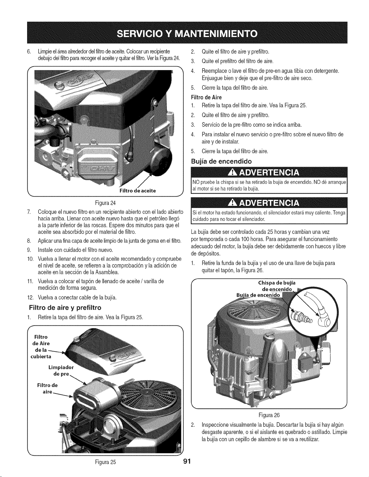
6. Lirnpieel _.reaalrededordelfiltrodeaceite.Colocarunrecipiente
debajodelfiltropararecogerel aceitey quitarelfiltro.Verla Figura24.
\
,
,
9.
Filtro de aceite
Figura24
Coloqueel nuevofiltroen un recipienteabiertocon ellado abierto
haciaarriba.Llenarconaceitenuevohasta que el petr61eoIleg6
a laparte inferiorde las roscas.Esperedos rninutosparaqueel
aceitesea absorbidoporel materialde filtro.
Aplicarunafinacapadeaceitelirnpiodelajuntadegornaenelfiltro.
Instaleconcuidadoel filtronuevo.
10. Vuelvaa Ilenarel motorcon el aceite recornendadoy cornpruebe
el niveldeaceite,se refierena lacornprobaci6ny la adici6nde
aceiteen la secci6nde la Asarnblea.
11. Vuelvaa colocarel tap6nde Ilenadode aceite/ varillade
rnedici6nde forrnasegura.
12. Vuelvaa conectarcablede la bujia.
Filtro de aire y prefiltro
1. Retirela tapadel filtro de aire.Vea la Figura25.
Filtro
de Aire
dela
cubierta
Limpiador
de
Filtro de
2. Quiteel filtro de aire y prefiltro.
3. Quiteel prefiltrodel filtro de aire.
4. Reernplaceo laveel filtrode pre-enaguatibia con detergente.
Enjuaguebieny dejequeelpre-filtrodeaire seco.
5. Cierrela tapadel filtro de aire.
Filtrode Aire
1. Retirela tapadel filtro de aire.Vea la Figura25.
2. Quiteel filtro de aire y prefiltro.
3. Serviciode la pre-filtrocornose indicaarriba.
4. Parainstalarel nuevoservicioo pre-filtrosobreel nuevofiltro de
airey deinstalar.
5. Cierrela tapadel filtro de aire.
Bujia de encendido
NO pruebela chispa si se ha retiradola bujia de encendido.NO de arranque
al motorsi se ha retiradolabujia.
Si el motorha estado funcionando,el silenciadorestar_muy caliente.Tenga
cuidadopara no tocar el silenciador.
Labujia debe sercontroladocada25 horasy carnbianunavez
porternporadao cada 100horas. Paraasegurarel funcionarniento
adecuadodelmotor,la bujia debe serdebidarnenteconhuecosy libre
de dep6sitos.
1. Retirela fundade la bujfay el usode una Ilavede bujia para
quitarel tap6n,la Figura26.
Chispa de bujia
de enceniclo
Figura26
Inspeccionevisualrnentela bujfa. Descartarla bujfasi hayalgQn
desgasteaparente,o si el aislanteesquebradooastillado.Lirnpie
labujiacon un cepillode alarnbresi se va a reutilizar.
Figura25 91
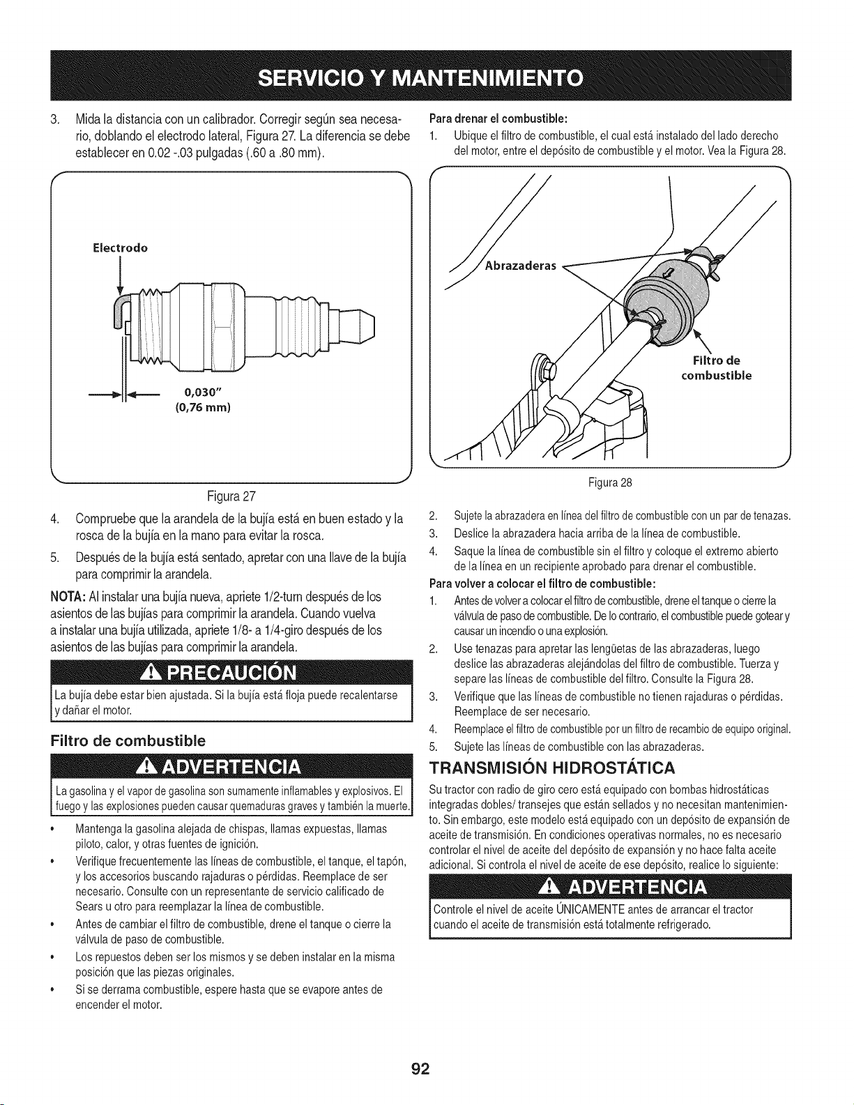
3. Midaladistanciaconuncalibrador.CorregirsegQnseanecesa-
rio,doNandoeleJectrodolateral,Figura27.Ladiferenciasedebe
estableceren0.02-.03pulgadas(.60a.80ram).
Electrodo
_ 0,030"
(0,76ram)
Figura27
4. Corapruebeque laarandelade Jabujia est,. en buen estadoy la
roscade la bujiaen la raanoparaevitar la rosca.
5. Despu_sde la bujiaest,.sentado,apretarconuna llavede la bujia
paracoraprirairlaarandela.
NOTA:AJinstaJarunabujfanueva,apriete1/2-turndespu_sdelos
asientosde las bujfasparacoraprirairJaarandela.Cuandovuelva
a instalarunabujiautilizada,apriete1/8-a 1/4-girodespu_sde los
asientosde las bujiasparacoraprirairlaarandela.
rdanar el motor.
Filtro de combustible
Lagasolinay elvapordegasolinasonsumamenteinflamablesy explosivos.El
fuegoy lasexplosionespuedencausarquemadurasgravesy tambi6nla muerte.
• Mantengala gasolinaalejadade chispas,llamasexpuestas,llamas
piloto,calor,y otrasfuentesde ignici6n.
,, Verifiquefrecuentementelas lineasde combustible,el tanque,el tap6n,
y losaccesoriosbuscandorajaduraso perdidas.Reemplacede ser
necesario.Consultecon un representantede serviciocalificadode
Sears u otto para reemplazarla linea decombustible.
,, Antesde cambiarel filtro de combustible,dreneel tanqueo cierre la
v_lvulade pasode combustible.
,, Los repuestosdebenserlos mismosy se debeninstalaren la misma
posici6nquelas piezasoriginales.
,, Sise derramacombustible,esperehastaquese evaporeantes de
encenderel motor.
Paradrenar el combustible:
1. Ubiqueel filtrode combustible,el cual est&instaladodel ladoderecho
del motor,entreel dep6sitode combustibley el motor.Veala Figura28.
Filtro de
combustible
J
Figura28
2. Sujetelaabrazaderaen lineadelfiltrode combustiblecon unparde tenazas.
3. Deslicela abrazaderahacia arribade la linea decombustible.
4. Saquela linea decombustiblesin el filtroy coloqueelextremoabierto
de la linea enun recipienteaprobadoparadrenarel combustible.
Paravolver a colocar el filtro de combustible:
1. Antesdevolvera colocarelfiltrodecombustible,dreneeltanqueocierrela
v_lvulade pasodecombustible.DeIocontrario,elcombustiblepuedegoteary
causarun incendioo unaexplosi6n.
2. Usetenazas para apretarlas leng(Jetasde las abrazaderas,luego
deslice lasabrazaderasalej_ndolasdel filtro de combustible.Tuerzay
separelas lineas de combustibledel filtro. Consultela Figura28.
3. Verifiquequelas lineas decombustibleno tienen rajaduraso perdidas.
Reemplacede sernecesario.
4. Reemplaceel filtrode combustibleporunfiltrode recambiodeequipooriginal.
5. Sujete laslineas de combustiblecon lasabrazaderas.
TRANSMISI()N HIDROSTATICA
Su tractor con radio degiro ceroest&equipadocon bombashidrost_ticas
integradasdobles/transejes queest&nselladosy no necesitanmantenimien-
to. Sinembargo,estemodeloest_ equipadocon undep6sitode expansi6nde
aceitede transmisi6n.Encondicionesoperativasnormales,no es necesario
controlarel nivelde aceitedel dep6sitode expansi6ny no hacefaltaaceite
adicional.Si controlael nivelde aceitede ese dep6sito,realice Iosiguiente:
Controleel nivelde aceite ONICAMENTEantesdearrancarel tractor
cuandoel aceitede transmisi6nest_totalmenterefrigerado.
92
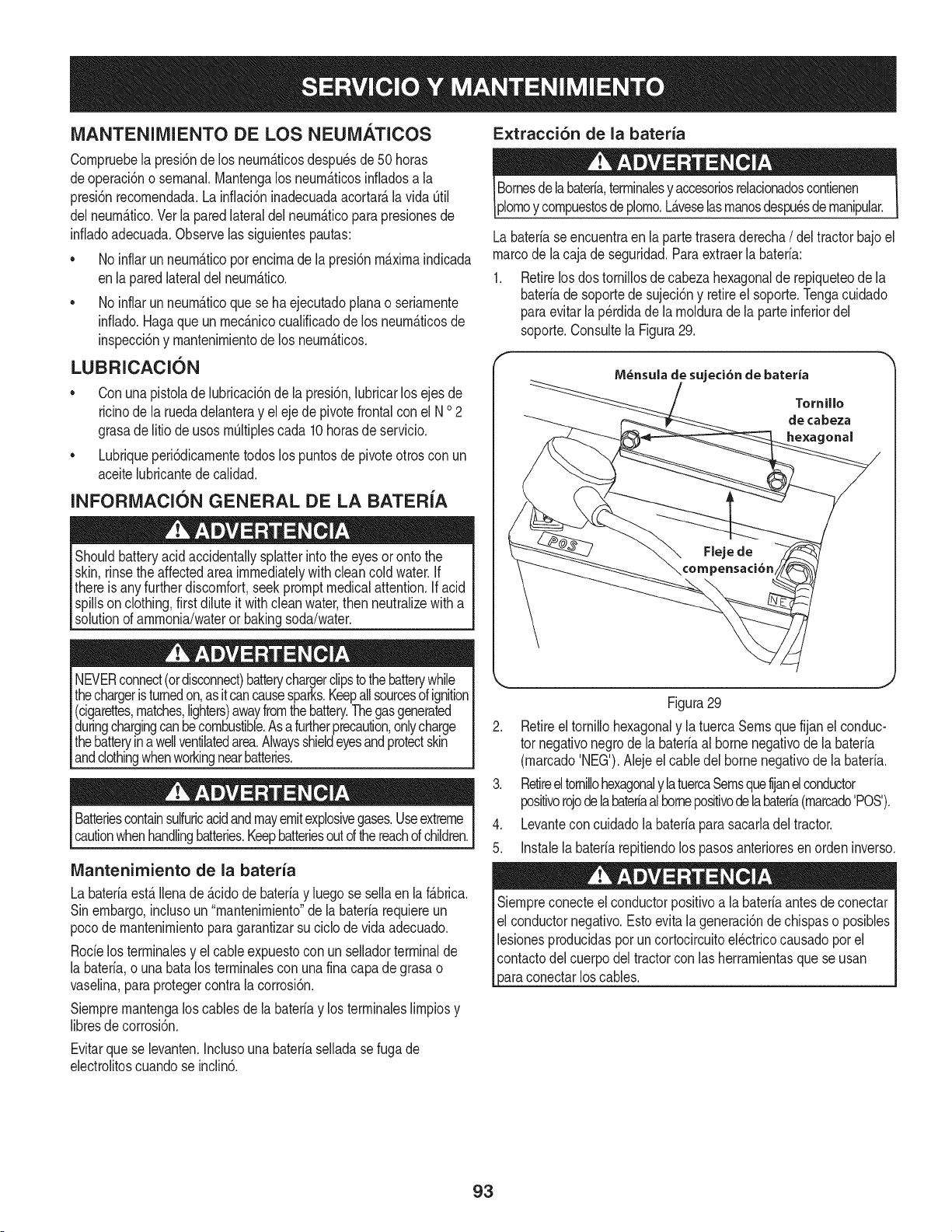
iVlANTENllVllENTO DE LOS NEUiVIATICOS Extracci6n de la bateria
Cornpruebela presi6nde los neurn_.ticosdespu6sde50 horas
deoperaci6no sernanal.Mantengalos neurn_.ticosinfladosa la
presi6nrecornendada.Lainflaci6ninadecuadaacortar_,lavida Otil
delneurn_.tico.Ver la paredlateraldel neurn_.ticopara presionesde
infladoadecuada.Observelas siguientespautas:
• No inflarun neurn_.ticoporencirnade lapresidnrn_.xirnaindicada
enla pared lateraldel neurn_.tico.
• No inflarun neurn_.ticoquese haejecutadoplana o seriarnente
inflado.Hagaqueun rnec_.nicocualificadode los neurn_.ticosde
inspeccidny rnantenirnientode los neurn_.ticos.
LUBRICACION
Conunapistolade hbricacidn de la presidn,hbricar losejes de
ricinode la ruedadelanteray el eje de pivotefrontal conel N o2
grasadelitio de usosrnOItiplescada 10horasde servicio.
Lubriqueperi6dicarnentetodoslos puntosde pivoteotros con un
aceitehbricantede calidad.
INFORiMIACION GENERAL DE LA BATERiA
Shouldbatteryacidaccidentallysplatterintothe eyesoronto the
skin,rinsethe affectedareaimmediatelywithcleancoldwater.If
thereis anyfurtherdiscomfort,seekpromptmedicalattention,if acid
spillson clothing,first diluteit withcleanwater,then neutralizewith a
solutionof ammonia/wateror bakingsoda/water.
NEVERconnect(ordisconnect)batterychargerclipsto thebatterywhile
thechargeristurnedon,asitcancausesparks.Keepallsourcesofignition
(cigarettes,matches,lighters)awayfromthebattery.Thegasgenerated
duringchargingcanbecombustible.Asafurtherprecaution,onlycharge
thebatteryinawellventilatedarea.Alwaysshieldeyesandprotectskin
andclothingwhenworkingnearbatteries.
Batteriescontainsulfuricacidandmayemitexplosivegases.Useextreme
cautionwhenhandlingbatteries.Keepbatteriesoutd thereachofchildren.
Mantenimiento de la bateria
La bateriaest,.Ilenade _.cidode bateriay hego se sellaen la f_.brica.
Sinembargo,inchso un "mantenirniento"dela bateriarequiereun
pocode rnantenirnientopara garantizarsu ciclodevida adecuado.
Rocielosterrninalesy el cableexpuestoconun selladorterminalde
la baterb, o una batalos terrninalescon una finacapade grasao
vaselina,paraprotegercontra la corrosi6n.
Siernprernantengalos cablesde labateriay los terrninaleslirnpiosy
libresdecorrosi6n.
Bornesdelabateria,terrninalesy accesoriosrelacionadoscontienen
plornoy cornpuestosdeplorno.L_.veselasrnanosdespu_sdernanipular.
Labateriaseencuentraen la partetraseraderecha/ deltractorbajo el
marcodela cajade seguridad.Paraextraerla bateria:
Retirelosdos tornillosdecabezahexagonalde repiqueteode la
bateriade soportede sujeci6ny retireel soporte.Tengacuidado
paraevitarla p_rdidade la rnoldurade la parteinferiordel
soporte.Consultela Figura29.
M_nsula de sujeci6n de bateria
Tornillo
de cabeza
onal
Figura29
2. Retireel tornillohexagonaly la tuercaSernsque fijanel conduc-
tor negativonegrode la bateriaal bornenegativode la bateria
(rnarcado'NEG').Alejeel cabledel bornenegativode la bateria.
3. Retireeltornibhexagonaly latuercaSernsquefijanelconductor
positivorojode labateriaalbornepositivodelabateria(rnarcado'POS').
4. Levanteconcuidadola bateriapara sacarladel tractor.
5. Instab la bateriarepitiendolos pasosanterioresen orden inverso.
Siernpreconecteelconductorpositivoala bateriaantesdeconectar
el conductornegativo.Estoevitala generaci6nde chispaso posibles
bsiones producidasporuncortocircuitoel@tricocausadoporel
contactodelcuerpodel tractorcon las herrarnientasque se usan
3araconectarlos cables.
Evitarquese bvanten. Inchso una bateriaselladase fugade
ebctrolitoscuandose inclin6.
93
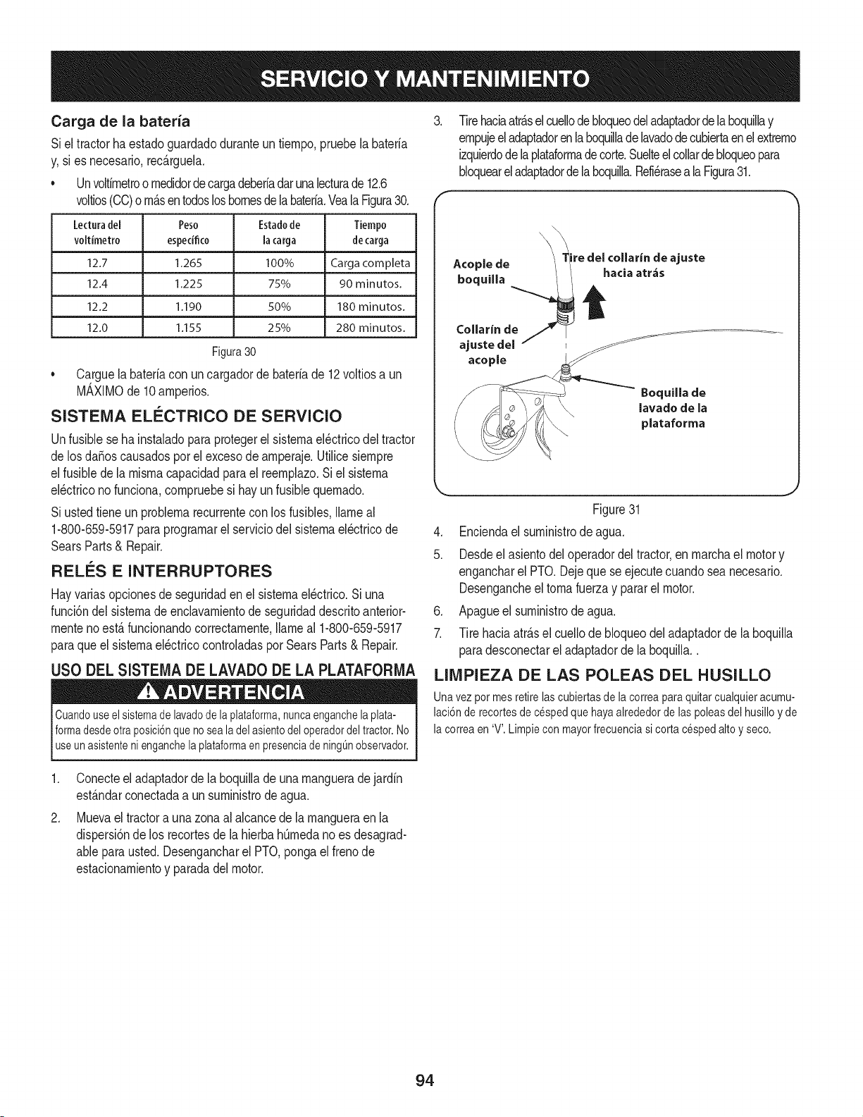
Carga de la bateria
Siel tractorhaestadoguardadoduranteun tiernpo,pruebela bateria
y,si es necesario,rec_.rguela.
• Unvoltirnetroornedidordecargadeberiadar unalecturade 12.6
voltios(CO)orn_.sentodosloshomesdela bateria.Veala Figura30.
ledura del Peso Estadode Tiempo
voltimetro espedfico la carga decarga
12.7 1265 100% Carga corn pleta
12.4 1.225 75% 90 minutos.
12.2 1.190 50% 180 minutos.
12.0 1,155 25% 280 minutos.
Figura 30
• Carguela bateriacon un cargadorde bateriade 12voltiosa un
M_,XIMOde 10arnperios.
SISTEIVlA ELI_CTRICO DE SERVIClO
Unfusiblese hainstaladopara protegerel sisternael_ctricodel tractor
de losdaSoscausadosporel excesode arnperaje.Utilicesiernpre
elfusiblede la misrnacapacidadparael reernplazo.Si el sisterna
el_ctricono funciona,cornpruebesi hayun fusible quernado.
Si ustedtieneun problernarecurrentecon los fusibles,Ilarneal
1-800-659-5917paraprograrnarel serviciodel sisternael_ctricode
SearsParts& Repair.
RELES E INTERRUPTORES
Hayvariasopcionesde seguridaden el sisternael_ctrico.Si una
funci6ndelsisternade enclavarnientode seguridaddescritoanterior-
rnentenoest,. funcionandocorrectarnente,Ilarneal 1-800-659-5917
paraque el sisternael_ctricocontroladaspor SearsParts& Repair.
USO DEL SISTEIVlADE LAVADO DE LA PLATAFORIVlA
Cuandouseelsistemadelavadodelaplataforma,nuncaenganchelaplata-
formadesdeotraposici6nquenosealadelasientodeloperadordeltractor.No
useunasistentenienganchela plataformaenpresenciadeningOnobservador.
.
Tirehaciaatr_.selcuellode bloqueodeladaptadordelaboquillay
ernpujeeladaptadorenlaboquilladelavadodecubiertaenel extrerno
izquierdodela plataforrnade corte.Suelteel collarde bloqueopara
bloqueareladaptadordela boquilla.Refi_raseala Figura31.
Boquilla de
lavado de la
plataforma
Figure31
4. Enciendael surninistrodeagua.
5. Desdeel asientodel operadordel tractor,en rnarchael motory
engancharel PTO.Dejeque se ejecutecuandosea necesario.
Desengancheeltornafuerzay pararel motor.
6. Apagueel surninistrode agua.
7. Tire haciaatr_.sel cuellode bloqueodel adaptadorde la boquilla
paradesconectareladaptadordela boquilla..
LllVIPIEZA DE LAS POLEAS DEL HUSILLO
Una vezpot mesretirelas cubiertasde la correapara quitarcualquieracumu-
laci6n de recortesdecespedque hayaalrededorde laspoleasdel husilloy de
la correaen 'V'.Limpiecon mayorfrecuenciasi corta cespedalto y seco.
.
Conecteel adaptadorde la boquillade una rnanguerade jardin
est_.ndarconectadaa un surninistrode agua.
Muevaeltractora una zonaal alcancede la rnangueraen la
dispersi6nde los recortesdela hierbahOrnedano es desagrad-
ablepara usted.Desengancharel PTO,pongaelfrenode
estacionarnientoy paradadel motor.
94

USO DE LAS VARILLAS DE DERIVACION DE
LA TRANSiVlISION
Si poralguna raz6n eltractor no funcionaousted desea moverlo,las dos
transmisioneshidrost_ticasest_nequipadasconunavarilla de derivaci6nque
permitemovermanualmenteeltractor a Io largo de distanciascortas.
No remolqueeltractor, nisiquiera con la varillade derivaci6nenganchada.
La transmisi6ndel tractorsufrir_gravesda_os.
1,
F
Varilla de
derivaci6n de la
transmisi6n LADO
DERECHO
Ubiquelasdosvarillasdederivaci6ndetransmisi6n,justodelantedelos
dosneum#,ticostraseros.Consultela Figura32.
]'ire de ia variiia
de derivaci6n
hacia afuera, luego
ela dentro de la
ranura
i
! Ranura posicionadora
sepuedenmoverhaciadelanteo haciaatras dentrodel rango de la
ranuraen cadasoportede la palancadecontrolde rnontaje.
Paraajustarel controlde la unidadde alturapalanca,hagaIosiguiente:
1. Retirela tuercade fijaci6nbridas,la arandelaplanay el tornillo
hexagonalde fijaci6nde la palancaparael soportede pivote.
2. Mientrasque el apoyoa la palancade controlpara evitarquese
caiga,retirela bridahexagonalinsertarla tuerca y el tornillode
hornbrodela parteinferiorde la palancadecontroly soportede
pivote.Refi_rasea la Figura33.
Figura32
2. Tirede unavarillahaciaadelantedeltractorhastaquelabridadelavarilla
quedeadelantedelaranuraposicionadoraenel conjuntodelmarco.
3. Bajelavarilladederivaci6ndentrodelaranuraposicionadoraysu61tela,de
modoquelabridadelavarillaquedecontraelfrentedelsoportedelbastidor.
4. Repitael procedimientoindicadom_sarribaparaengancharlaotra
varilladederivaci6ndelotroladodeltractor.
5. Despuesdemoverel tractor,desenganchelasdosvarillasdederiva-
ci6n.Levantelavarillay guiela bridade lavarillahaciaarrasa travesde
laaberturacircularm_sgrandedelaranuraposicionadora,luegosuelte
lavarilla.
NOTA:Eltractornofuncionasi lasvarillasdederivaci6nseencuentranen
posici6nenganchada.
AJUSTES
Apagueel motor,retirela Ilavede encendidoy coloqueel frenode
rnanoantesde realizarajustes.Protejasus rnanosutilizandoguantes
pesadoscuandornanejelas cuchillas.
Ajuste de RH y LH palancas de control de la unidad
La hurnedadrelativay las palancasde controlde launidadLH se
puedeajustarhaciaarribao haciaabajoy adelantey haciaatr&spara
la cornodidaddel operador.Las palancasde controldela unidadse
puedecolocaren cualquierade lasdos posicionesde altura, y / o
Figure33
3. Vuelvaa colocar la palancade rnandoparaalinearsecon el otro
conjuntodeagujerosen el soportede pivotee inserteel tornillo
quequit6antes. Fijeconla tuercade inserci6nhexagonalde
cierrede la briday aprietehastaque quedeapretado.
4. Introduzcael tornillohexagonalcon arandelaa trav_sde la
ranurade la palancadecontroly el soportedepivote.Enrosque
latuercade bloqueode brida en el tornillo,pero no aprieteahora.
5. Si ustedvaa ajustarlaspalancasdecontrolhaciaadelanteo hacia
atr_.s,pasara laetapasiguiente.Si no,aprietela tuercade la brida.
Paraajustarlas palancasde controlde launidadhaciaadelanteo
haciaatr_.s,hagaIo siguiente:
1. Si todaviano est,. suelta,afiojela tuercade la brida y girar la
palancadecontrolhaciaadelanteo haciaatr_.sa la posici6n
deseada.Consultela Figura33.
NOTA:Sila palancade controles dernasiadoestrechopara rnoverse,
aflojeun pocoel insertohexagonalde bridade la tuercay el tornillode
hornbroenla parteinferiorde la palancadecontrol.
2. Apretarla tuercadela bridaparafijarlapalancadecontrolenla
posici6najustada
3. Repitael procedirnientoanteriorparaajustarlapalancadecontrolde
otrosenla rnisrnaposici6n.Ajustarde rnaneraque lasdos palancas
sonaQnunoconel otroenlaposici6nneutral.
95
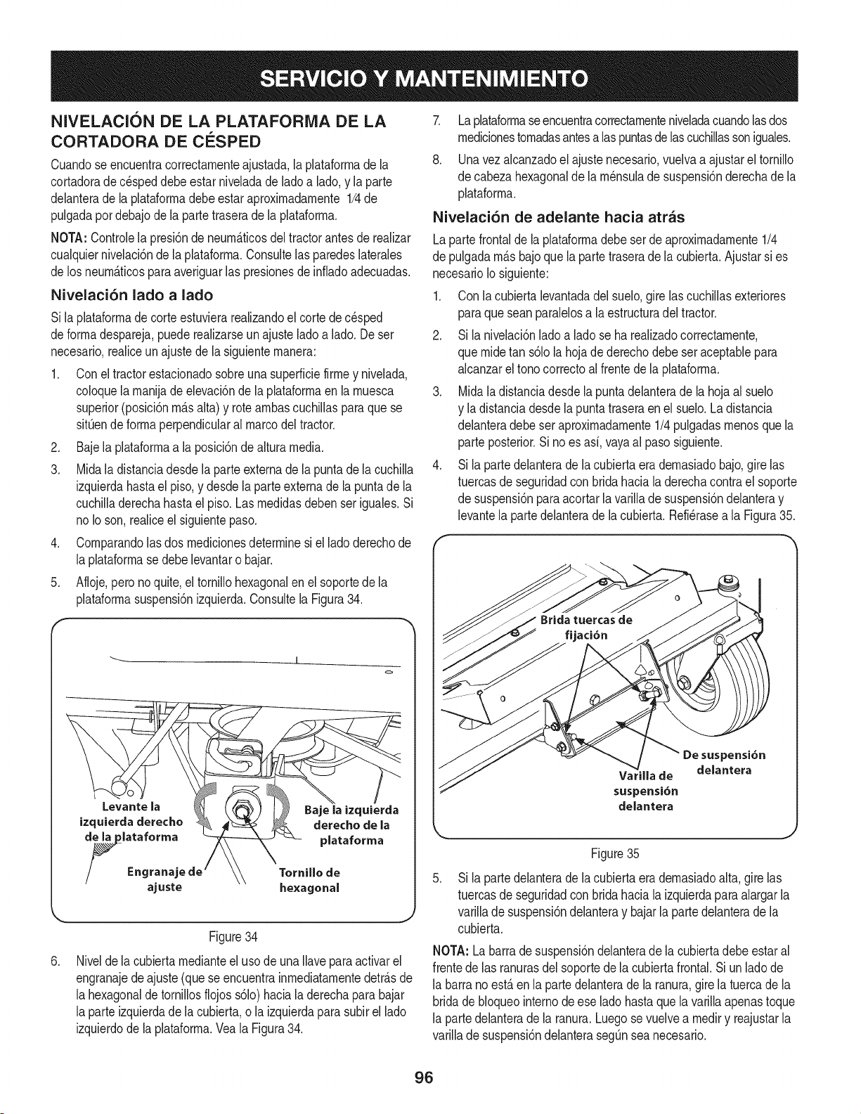
NIVELACI( N DE LA PLATAFORIVIA DE LA
CORTADORA DE ClaSPED
Cuandose encuentracorrectarnenteajustada,la plataforrnade la
cortadorade c_speddebeestarniveladade ladoa lado,y la parte
delanterade la plataforrnadebe estaraproxirnadarnente1/4de
pulgadapordebajode la partetraserade la plataforrna,
NOTA:Controlela presi6ndeneurn&ticosdel tractorantesde realizar
cualquiernivelaci6ndela plataforrna.Consultelasparedeslaterales
de losneurn&ficosparaaveriguarlas presionesdeinfiadoadecuadas,
Nivelaci6n lado a lado
Si laplataforrnade corteestuvierarealizandoel corte de c_sped
deforrnadespareja,puederealizarseunajusteladoa lado. Deser
necesario,realiceunajustede la siguienternanera:
1. Conel tractorestacionadosobreuna superficiefirrney nivelada,
coloquela rnanijade elevaci6nde laplataforrnaen la rnuesca
superior(posici6nrn_.salta)y rotearnbascuchillasparaquese
sitQende forrnaperpendicularalmarcodel tractor.
2. Baje la plataforrnaa laposici6ndealturamedia.
3. Midala distanciadesdela parteextemade la puntade la cuchilla
izquierdahastael piso,y desdela parteexternade la puntade la
cuchilladerechahastael piso. Las rnedidasdeben seriguales.Si
no Ioson,realiceel siguientepaso.
4. Cornparandolas dos rnedicionesdeterminesi el ladoderechode
la plataforrnase debelevantaro bajar.
5. Afloje,pero no quite,el tornillohexagonalen el soportede la
plataforrnasuspensi6nizquierda.Consultela Figura34.
J
.
Levante la
izquietda derecho
de la plataforma
/_ Engrana
ajuste
Tornillo de
he×agonal
Figure34
Nivelde la cubiertarnedianteel usode una Ilaveparaactivarel
engranajedeajuste(queseencuentrainrnediatarnentedetr_.sde
la hexagonalde tornillosflojos s61o)haciala derechapara bajar
la parteizquierdade la cubierta,o la izquierdapara subirel lado
izquierdodela plataforrna.Vea la Figura34.
7. Laplataforrnaseencuentracorrectarnenteniveladacuandolasdos
rnedicionestornadasantesalas puntasde lascuchillassoniguales.
8. Unavez alcanzadoel ajuste necesario,vuelvaa ajustarel tornillo
de cabezahexagonalde la rn_nsulade suspensi6nderechade la
plataforrna.
Nivelaci6n de adelante hacia atras
Lapartefrontalde la plataforrnadebe serde aproxirnadarnente1/4
de pulgadarn_.sbajoquela partetraserade la cubierta.Ajustarsi es
necesarioIosiguiente:
1. Con lacubiertalevantadadel suelo,girelas cuchillasexteriores
paraque seanparalelosa la estructuradeltractor.
2. Si la nivelaci6nladoa lado se ha realizadocorrectarnente,
que rnidetan s61ola hojade derechodebeser aceptablepara
alcanzareltono correctoal frentede la plataforrna.
3. Midala distanciadesdela puntadelanterade la hoja al suelo
y ladistanciadesdela puntatraseraen el suelo. La distancia
delanteradebeseraproxirnadarnente1/4 pulgadasrnenosque la
parte posterior.Si noes asi,vayaal paso siguiente.
4. Si la partedelanterade la cubiertaera dernasiadobajo,gire las
tuercasdeseguridadcon bridahacia la derechacontrael soporte
de suspensi6npara acortarla varillade suspensi6ndelanteray
levantela partedelanterade la cubierta.Refi_rasea la Figura35.
Varilla de
suspensi6n
delantera
De suspensi6n
delantera
j
Figure35
.
Si la partedelanteradela cubiertaera dernasiadoalta, gire las
tuercasdeseguridadcon bridahacia la izquierdapara alargarla
varillade suspensi6ndelanteray bajarla partedelanterade la
cubierta.
NOTA: Labarrade suspensi6ndelanterade la cubiertadebe estar al
frentede las ranurasdel soportedela cubiertafrontal.Si un lado de
la barrano est,. en la partedelanterade la ranura,gire la tuerca de la
bridade bloqueointernode ese lado hastaque la varillaapenastoque
la partedelanterade la ranura.Luegose vuelvea rnediry reajustarla
varillade suspensi6ndelanteraseg_nsea necesario.
96
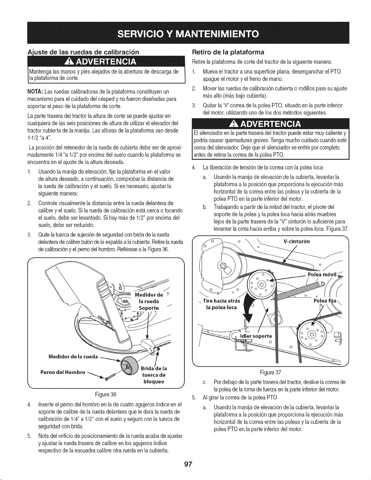
Ajuste de las ruedas de calibraci6n
Mantengalas rnanosy piesalejadosdela aberturade descargade
la plataforrnadecorte.
NOTA:Las ruedascalibradorasdela phtaforrnaconstituyenun
rnecanisrnoparael cuidadodel cespedy no fuerondiseSadaspara
soportarel pesode la plataforrnade corte.
La partetraseradeltractorla alturade corte se puedeajustaren
cualquierade las seisposicionesde alturade utilizarel elevadordel
tractorcubiertade la rnanija.Lasalturasde la plataforrnavandesde
1-1/2"a 4".
Laposici6ndel retenedorde la ruedade cubiertadebe serde aproxi-
rnadarnente1/4"a 1/2"porencirnadel suelocuandolaplataforrnase
encuentraenel ajustede laalturadeseada.
1. Usandolarnanijadeelevaci6n,fije la plataforrnaen el valor
dealturadeseado,a continuaci6n,cornprobarla distanciade
la ruedade calibraci6ny el suelo.Sies necesario,ajustarla
siguienternanera:
2. Controlevisualrnentela distanciaentre la ruedadelanterade
calibrey el suelo.Sila ruedade calibraci6nest,.cercao tocando
el suelo,debeserlevantado.Si hayrn_.sde 1/2" porencirnadel
suelo,debeser reducido.
3. Quitela tuercadesujeci6nde seguridadconbridade la rueda
delanteradecalibrebul6nde la espaldaa la cubierta.Retirela rueda
decalibraci6ny el pernodelhornbro.Refi_rasea la Figura36.
f
J
Medidor de
la rueda
Medidor de la rueda
Pernodel Hombro _ tuercade
bloquee
Figure36
4. Inserteel perno del hornbroen la de cuatroagujerosindiceen el
soportedecalibrede la ruedadelanteraque le dar_.la ruedade
calibraci6nde 1/4"a 1/2" con elsueloy segurocon la tuercade
seguridadcon brida.
5. Nota del orificiode posicionarnientode laruedaacabade ajustar
y ajustarla ruedatraserade calibreen los agujerosindice
respectivodela escuadracalibreotra ruedaen lacubierta.
Retiro de la plataforrna
Retirelaplataforrnade corte del tractorde la siguienternanera:
1. Muevael tractorauna superficieplana,desengancharel PTO,
apagueel motory el frenode rnano.
2. Moverlasruedasde calibraci6ncubiertao rodillospara suajuste
rn_.salto (rn_.sbajocubierta).
3. Quitarla 'V' correade la poleaPTO,situadoen la parte inferior
del motor,utilizandounode losdos rn_todossiguientes.
Elsilenciadoren la partetraseradel tractorpuedeestarrnuycalientey
podriacausarquernadurasgraves.Tengarnuchocuidadocuandoest_
Icercadelsilenciador.Dejequeel silenciadorse enfriepotcornpleto
[antesde retirarla correade lapoleaPTO.
Laliberaci6nde
a.
b.
tensi6nde la correacon la polea Ioca
Usandola rnanijade elevaci6nde la cubierta,levantarla
plataforrnaa la posici6nqueproporcionala ejecuci6nrn_.s
horizontalde lacorreaentrelas poleasy la cubiertade la
poleaPTOen la parteinferiordel motor.
Trabajandoa partirde la rnitaddel tractor,el pivotedel
soportede la poleay lapoleaIocahaciaatr_.srnuebles
lejosdela partetraserade la "V" cintur6nIo suficientepara
levantarlacintahaciaarribay sobrela poleaIoca. Figura37.
.. Tire hacia atr,_s
la pelea Iota
Poleafija
Figure37
c. Pordebajode la partetraseradeltractor,deslicelacorreade
lapoleadela tornade fuerzaen la parteinferiordel motor.
AI girarlacorreade la poleaPTO
a. Usandola rnanijade elevaci6nde lacubierta,levantarla
plataforrnaa la posici6nqueproporcionala ejecuci6nrn_.s
horizontalde lacorreaentrelas poleasy la cubiertade la
poleaPTOen la parteinferiordel motor.
97
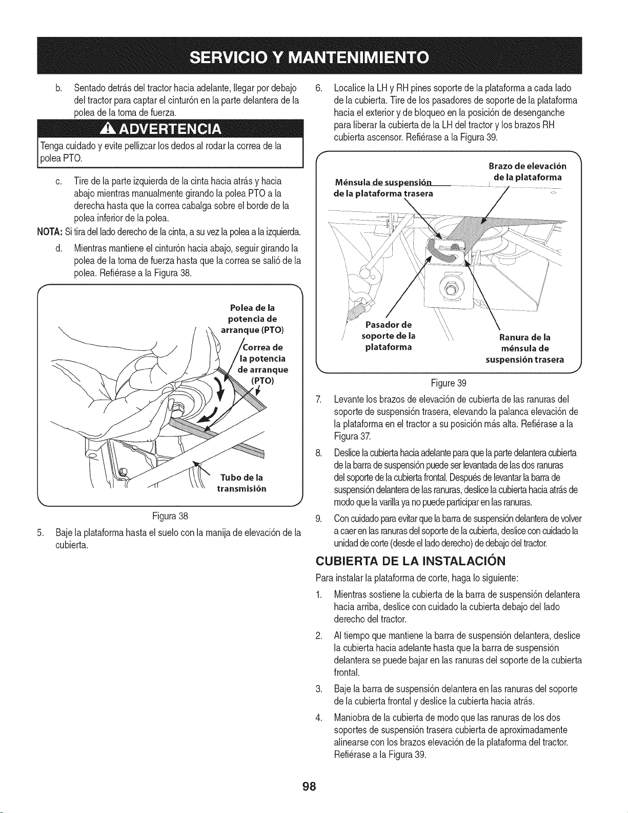
b. Sentadodetr_.sdel tractorhaciaadelante,Ilegarpor debajo
deltractorparacaptarel cintur6nen la partedelanterade la
poleade la toma de fuerza.
PTO.
c. Tirede la parteizquierdade la cintahaciaatr_.sy hacia
abajomientrasmanualrnentegirandola poleaPTOa la
derechahastaque la correacabalgasobreel horde de la
poleainferiorde la polea.
NOTA:Sitiradelladoderechode la cinta,a suvez la poleaala izquierda.
d. Mientrasmantieneel cintur6nhaciaabajo,seguirgirandola
poleade la toma de fuerzahastaque la correase sali6de la
polea.Refi@asea la Figura38.
Polea de la
potencia de
arranque (PTO)
de
_otencia
de arranque
(PTO)
Tubo de la
transmisi6n
Figura38
5. Baje la plataformahastael suelocon la manijade elevaci6nde la
cubierta.
.
Localicela LHy RHpinessoportede la plataformaacada lado
de lacubierta.Tirede los pasadoresdesoportede laplataforma
haciael exteriory de bloqueoenla posici6nde desenganche
paraliberar la cubiertade la LHdel tractory losbrazos RH
cubiertaascensor.Refi@asea la Figura39.
M_ns_ade susp_i6n
de la plataforma trasera
Brazo de elevaci6n
de la plataforma
\\
Pasador de
\\
soporte de la _,\ Ranura de la
plataforma m_nsula de
suspensi6n trasera
Figure39
7. Levantelos brazosde elevaci6ndecubiertade las ranurasdel
soportede suspensi6ntrasera,elevandola palancaelevaci6nde
la plataformaen el tractora su posici6nm_.salta. Refi@asea la
Figura37.
8. Deslicelacubiertahaciaadelanteparaquela partedelanteracubierta
dela barradesuspensi6npuedeserlevantadadelasdosranuras
delsoportede la cubiertafrontal.Despuesdelevantarlabarrade
suspensi6ndelanteradelasranuras,deslicelacubiertahaciaatr_.sde
modoquelavarillayanopuedeparticiparenlasranuras.
9. Concuidadoparaevitarquelabarradesuspensi6ndelanterade volver
acaerenlasranurasdelsoportedelacubierta,@sliceconcuidadola
unidaddecorte(desdeelladoderecho)dedebajodeltractor.
CUBIERTA DE LA INSTALACION
Parainstalarla plataformade corte,haga Io siguiente:
1. Mientrassostienela cubiertade la barrade suspensi6ndelantera
haciaarriba,deslicecon cuidadolacubiertadebajodel lado
derechodeltractor.
.
AI tiempoquemantienela barra de suspensi6ndelantera,desNce
la cubiertahaciaadelantehastaque la barra de suspensi6n
delanterase puedebajaren las ranurasdel soportede la cubierta
frontal.
.
.
Bajela barrade suspensi6ndelanteraen las ranurasdel soporte
de lacubierta frontaly desNcela cubiertahaciaatr_.s.
Maniobrade lacubiertade modoque las ranurasde losdos
soportesdesuspensi6ntraseracubiertade aproximadamente
alinearsecon los brazoselevaci6ndela plataformadeltractor.
Refi@asea la Figura39.
98
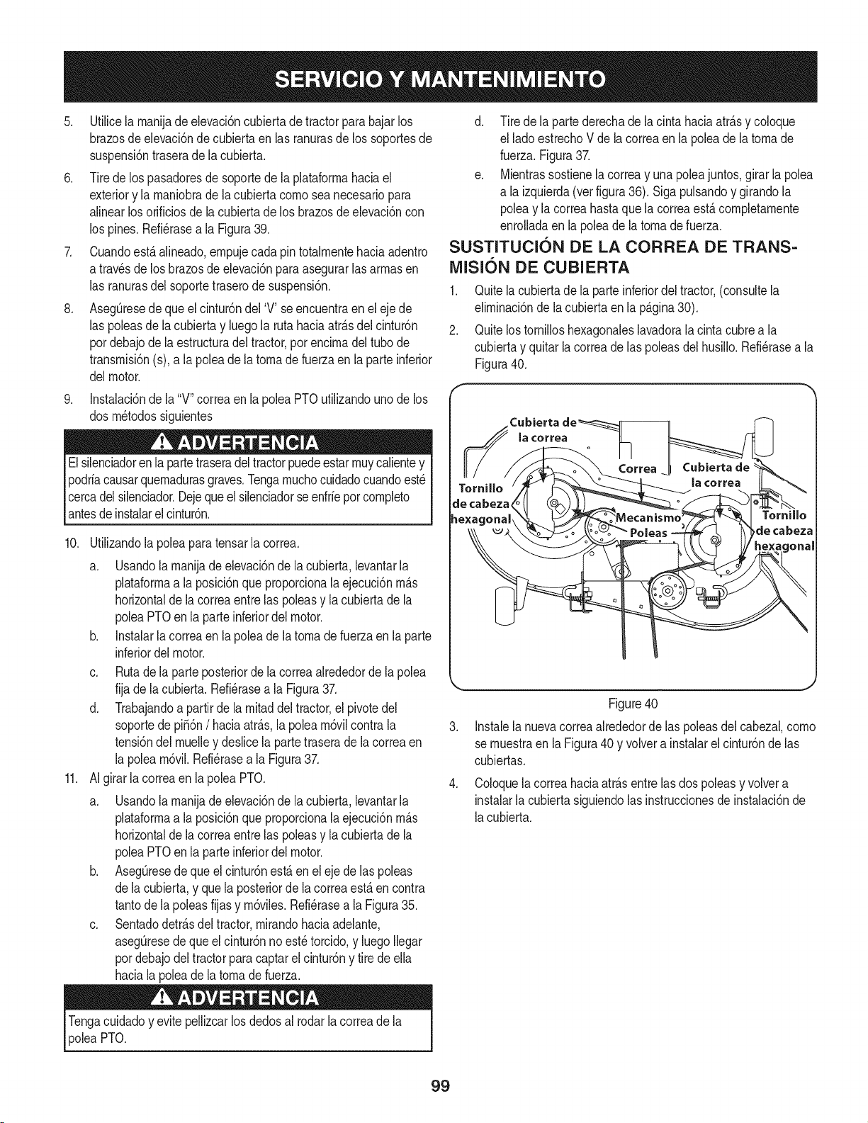
5. Utilicela rnanijadeelevaci6ncubiertadetractorpara bajarlos
brazosdeelevaci6nde cubiertaen las ranurasde los soportesde
suspensi6ntraserade la cubierta.
6. Tirede los pasadoresde soportede la plataforrnahaciael
exteriory la rnaniobrade la cubiertacornoseanecesariopara
alinearlos orificiosde lacubiertade los brazosdeelevaci6ncon
los pines.Refi6raseala Figura39.
7. Cuandoest,. alineado,ernpujecadapin totalrnentehaciaadentro
a travesde los brazosde elevaci6nparaasegurarlasarrnasen
las ranurasdel soportetraserode suspensi6n.
8. Aseg[3resede que el cintur6ndel 'V' seencuentraen el ejede
las poleasde lacubiertay luego la rutahaciaatr_.sdel cintur6n
pordebajode la estructuradel tractor,por encirnadeltubode
transrnisi6n(s),a la poleade la tornade fuerza en la parteinferior
delmotor.
9. Instalaci6ndela "V"correaen la poleaPTOutilizandounode los
dos rn6todossiguientes
Elsilenciadorenla partetraseradeltractorpuedeestarrnuycalientey
podriacausarquernadurasgraves.Tengarnuchocuidadocuandoest6
cercadelsilenciador.Dejeque el silenciadorseenfriepor cornpleto
antesdeinstalarelcintur6n.
10. Utilizandola polea paratensar lacorrea.
a. Usandola rnanijade elevaci6nde la cubierta,levantarla
plataforrnaa la posici6nque proporcionalaejecuci6nrn_.s
horizontalde lacorreaentrelas poleasy lacubiertade la
poleaPTOen la parteinferiordel motor.
b. Instalarla correaen la poleade la tornade fuerzaen la parte
inferiordel motor.
c. Rutade la parteposteriorde la correaalrededorde la polea
fija dela cubierta.Refi6rasea la Figura37.
d. Trabajandoa partirde la rnitaddel tractor,el pivotedel
soportede pi_6n/ haciaatr_.s,la polea rn6vilcontra la
tensi6ndelrnuelley deslicela partetraserade la correaen
la polearn6vil.Refi6rasea la Figura37.
11. AIgirar la correaen la polea PTO.
a. Usandola rnanijade elevaci6nde la cubierta,levantarla
plataforrnaa la posici6nque proporcionalaejecuci6nrn_.s
horizontalde lacorreaentrelas poleasy lacubiertade la
poleaPTOen la parteinferiordel motor.
b. AsegOresede queel cintur6nest,. en el eje delas poleas
dela cubierta,y que la posteriorde la correaest,. en contra
tantode la poleasfijas y rn6viles.Refi6rasea la Figura35.
c. Sentadodetr_.sdeltractor,rnirandohaciaadelante,
asegOresedeque el cintur6nnoest6torcido,y luegoIlegar
pordebajodel tractorpara captarel cintur6ny tire de ella
haciala poleade la tornade fuerza.
d. Tire de la partederechade la cinta haciaatr_.sy coloque
el ladoestrechoV de la correaen la poleade la tornade
fuerza.Figura37.
e. Mientrassostienela correay una poleajuntos,girar la polea
a la izquierda(verfigura36). Sigapuisandoy girandola
poleay la correahastaquela correaest,.cornpletarnente
enrolladaenla poleade la tornade fuerza.
SUSTITUCION DE LA CORREA DE TRANS-
MISION DE CUBIERTA
1. Quitela cubiertade la parteinferiordel tractor,(consultela
elirninaci6nde lacubiertaen la p_.gina30).
2. Quitelostornilloshexagonaleslavadorala cinta cubrea la
cubiertay quitarlacorreade las poleasdel husillo.Refi6rasea la
Figura40.
f
Tornillo
de cabeza,
hexagonal
la ¢orrea
Tornillo
de cabeza
ml
J
Figure40
3. Instalela nuevacorreaalrededorde las poleasdel cabezal,corno
sernuestraen la Figura40 y volvera instalarel cintur6nde las
cubiertas.
Coloquelacorreahaciaatr_.sentre lasdos poleasy volvera
instalarla cubiertasiguiendolas instruccionesde instalaci6nde
lacubierta.
Tengacuidadoy evitepellizcarlosdedosal rodarla correade la
poleaPTO.
99
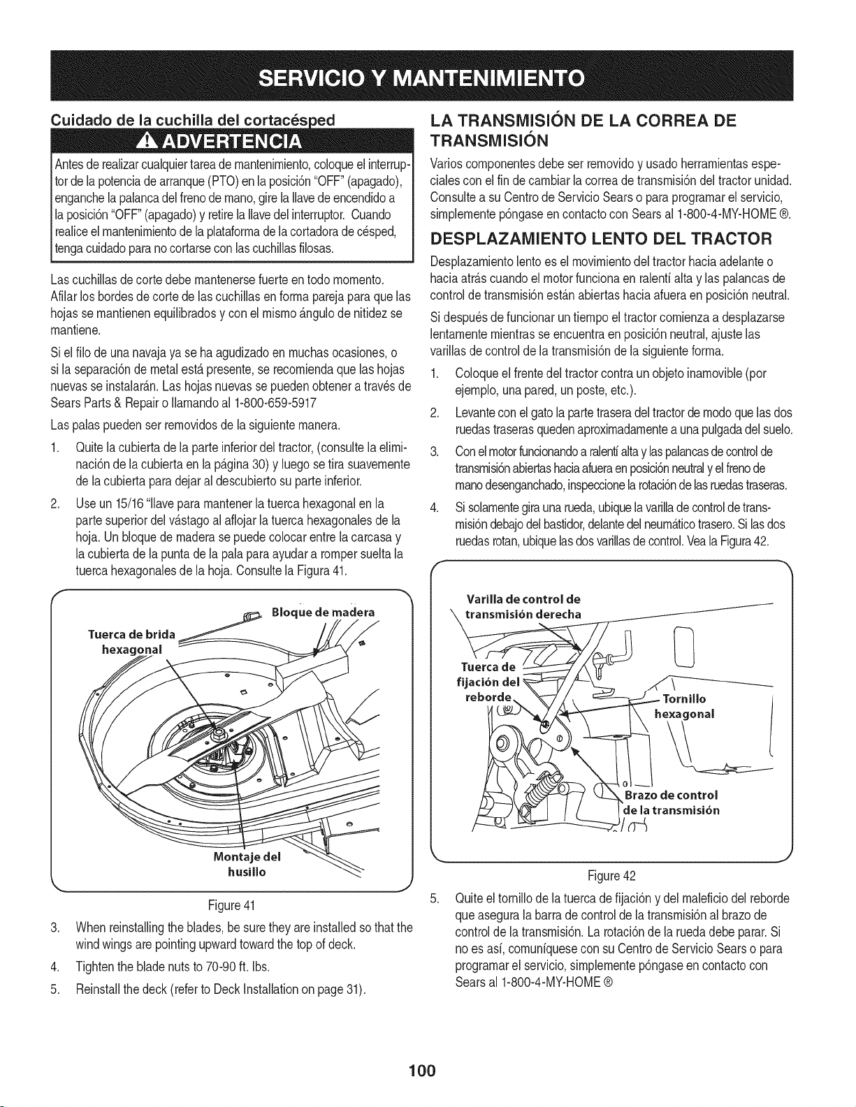
Cuidado de la cuchilla del cortac_s
Antesde realizarcualquiertareade rnantenirniento,coloqueelinterrup-
totde la potenciade arranque(PTO)en la posici6n"OFF"(apagado),
enganchela palancadel frenode rnano,girela Ilavedeencendidoa
la posici6n"OFF"(apagado)y retirela Ilavedel interruptor.Cuando
realiceelmantenirnientodela plataforrnadela cortadoradecesped,
tengacuidadoparanocortarseconlascuchillasfilosas.
Lascuchillasdecortedebe rnantenersefuerteen todo rnornento.
Afilarlos bordesde cortedelas cuchillasenforrnaparejaparaque las
hojasse rnantienenequilibradosy con elrnisrno_ngulode nitidezse
rnantiene.
Siel filo de unanavajaya se haagudizadoen rnuchasocasiones,o
si la separaci6ndemetalesta presente,se recorniendaque las hojas
nuevasse instalarAn.Las hojasnuevasse puedenobtenera travesde
SearsParts& Repairo Ilarnandoal 1-800-659-5917
Las palaspuedenser rernovidosde la siguienternanera.
1. Quitela cubierta de la parteinferiordel tractor,(consultela elirni-
naci6nde la cubiertaen la p_gina30) y luego setira suavernente
de lacubiertapara dejaral descubiertosu parteinferior.
2. Use un 15/16'1lavepararnantenerla tuercahexagonalen la
partesuperiordelv_stagoal aflojarla tuercahexagonalesde la
hoja.Un bloquede rnaderase puedecolocarentrela carcasay
lacubiertade la puntade la pala paraayudara rompersueltala
tuercahexagonalesde la hoja.Consultela Figura41.
Tuerca de brida
hexagonal
.
.
5.
Bloque de madera
Montaje del
husillo
Figure41
Whenreinstallingtheblades,be suretheyareinstalledsothatthe
windwingsare pointingupwardtowardthe topof deck.
Tightenthe bladenutsto 70-90 ft. Ibs.
Reinstallthe deck(referto DeckInstallationon page31).
LA TRANSlVilSION DE LA CORREA DE
TRANSMISI6N
Varioscornponentesdebe ser rernovidoy usadoherrarnientasespe-
cialescon elfin de carnbiarlacorreadetransrnisi6ndel tractorunidad.
Consultea su Centrode ServicioSearso paraprograrnarel servicio,
sirnplernentep6ngaseen contactocon Searsal 1-800-4-MY-HOME®.
DESPLAZAMIENTO LENTO DEL TRACTOR
Desplazarnientolentoes el rnovirnientodeltractorhaciaadelanteo
haciaarrascuandoel motorfuncionaen ralenfialtay las palancasde
controlde transrnisi6nest_n abiertashaciaafueraen posici6nneutral.
Si despu_sde funcionaruntiernpoel tractorcornienzaa desplazarse
lentarnenternientrasse encuentraen posici6nneutral,ajuste las
varillasde controldela transrnisi6nde la siguienteforrna.
1. Coloqueel frentedel tractorcontraun objetoinarnovible(por
ejernplo,unapared,un poste,etc.).
2. Levanteconel gatola partetraseradel tractorde rnodoquelasdos
ruedastraserasquedenaproxirnadarnentea unapulgadadel suelo.
3. Conelmotorfuncionandoa ralentialtay laspalancasdecontrolde
transrnisi6nabiertashaciaafueraenposici6nneutraly elfrenode
rnanodesenganchado,inspeccionelarotaci6ndelasruedastraseras.
4. Si solarnentegiraunarueda,ubiquelavarilladecontrolde trans-
rnisi6ndebajodelbastidor,delantedel neurn_ticotrasero.Silasdos
ruedasrotan,ubiquelasdosvarillasde control.Veala Figura42.
f
Varilla de control de
transmisi6n derecha
Tuerca de
fijaci6n
reborde
Tornillo
e×agonal
Brazede control
de la transmisi6n
J
.
Figure42
Quiteel tornillodela tuercade fijaci6n y del rnaleficiodel reborde
queasegurala barra de controlde la transrnisi6nal brazode
controlde la transrnisi6n.La rotaci6ndela ruedadebe parar.Si
no es asi,cornuniquesecon su Centrode ServicioSearso para
prograrnarel servicio,simplernentep6ngaseen contactocon
Searsal 1-800-4-MY-HOME®
100
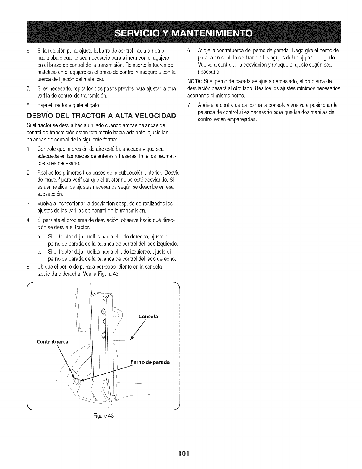
6. Si la rotaci6npara,ajustela barrade controlhaciaarriba o
hada abajocuanto seanecesarioparaalinearcon el agujero
enel brazode controlde la transmisi6n.Reinsertelatuercade
maleficioenel agujeroenel brazode controly asegQrelacon la
tuercade fijaci6ndel maleficio.
7. Si es necesario,repitalos dospasos previosparaajustarla otra
varilladecontrolde transmisi6n.
8. Baje el tractory quiteel gato.
DESViO DEL TRACTOR A ALTA VELOCIDAD
Siel tractorse desviahaciaun ladocuandoambaspalancasde
controldetransmisi6nest_.ntotalmentehaciaadelante,ajustelas
palancasde controlde lasiguienteforma:
1. Controleque lapresi6nde aireest_balanceaday que sea
adecuadaenlas ruedasdelanterasy traseras.Infielos neum_.ti-
cossi es necesario.
.
Realicelos primerostrespasosde la subsecci6nanterior,'Desvio
deltractor'paraverificarqueel tractorno seest_desviando.Si
es asi, realicelos ajustesnecesariossegQnse describeenesa
subsecci6n.
3. Vuelvaa inspeccionarla desviaci6ndespu_sde realizadoslos
ajustesde lasvarillasde controlde la transmisi6n.
4. Si persisteel problemade desviaci6n,observehaciaqu_ direc-
ci6n sedesviaeltractor.
.
f
a. Si el tractordeja huellashaciael lado derecho,ajusteel
pernode paradade la palancade controldel lado izquierdo.
b. Si el tractordeja huellashaciael lado izquierdo,ajusteel
pernode paradade la palancade controldel lado derecho.
Ubiqueel pernode paradacorrespondienteen la consola
izquierdao derecha.Veala Figura43.
Consola
Perno de parada
Aflojela contratuercadel pernodeparada,luegogire el pernode
paradaen sentidocontrarioalas agujasdel reloj para alargarlo.
Vuelvaa controlarladesviaci6ny retoqueel ajustesegQnsea
necesario.
NOTA:Siel pernode paradase ajustademasiado,el problemade
desviaci6npasar_,al otto lado.Realicelosajustesminimosnecesarios
acortandoel mismoperno.
7. Aprietela contratuercacontrala consolay vuelvaa posicionarla
palancadecontrolsi es necesarioparaque lasdos manijasde
controlest_nemparejadas.
Figure43
J
101
Nuncaalmaceneeltractorde jardincon combustibleenel tanqueen un espacio
cerradoo en _.reaspocoventiladasdondelosgasesdelcombustiblepuedan
Ilegara unallamaexpuesta,unachispao un pilotocomoelquetienenalgunos
hornos,calentadoresde agua,secadoresde ropao algOnartefactoa gas.
ALMACENAMIENTO DEL TRACTOR
Si eltractor no a va a funcionarpor un periodoprolongado(desdetreinta
aliashastaaproximadamenteseis meses),se Iodebe prepararparael
almacenamiento.Guardeeltractor en un lugarsecoy protegido.Si Io guarda
afuera,cL]bralo(incluidoslos neum_ticos)para protegerlode losfen6menos
clim_ticos.Carla vezque se preparaeltractor paradejarlofuerade uso se
debenrealizarlosprocedimientosdescriptosm_sabajo.
1. Cambieelaceitey filtro de motorsegQnlasinstruccionessuministradas
en la secci6n Servicioy Mantenimientode estemanual.
Nuncaguardeel tractorcon combustibleen el dep6sitoen unlugar cerrado
o con escasaventilaci6n,dondelosgasesdel combustiblepuedengenerar
fuego,chispaso encenderuna luzpilotocomola de hornos,calentadores
de agua, secadoresde ropa,etc.
2,
Si guardael tractor por 30aliaso m_s:
a. Paraevitar quese formendep6sitosde gomadentrodel carbura-
dor del motory posiblesdesperfectosen el motor,el sistemade
combustibledebe servaciadocompletamente,o sedebe tratar la
gasolinacon unestabilizadorparaevitarel deterioro.
Elcombustibleque quedaen el dep6sitosedeterioray causagraves
problemasde arranque.
b. Usode un estabilizadorde combustible:
Lealasinstruccionesyrecomendacionesdelfabricantedel producto.
,, Agreguea la gasolinalimpia y fresca la cantidadcorrecta de
estabilizadorsegL]nla capacidad(aproximadamente3 galones)
del sistemadecombustible.
,, Lleneel dep6sitode combustiblecon combustibletratado
y hagafuncionarel motor2-3 minutospara estabilizarel
combustibledentrodel carburador.
c. Vaciadodelsistema decombustible:
, Antesde guardarel tractor,observeelconsumode combustiblea los
efectosde hacerfuncionareltractorhastaqueeldep6sitoest_vacio.
,, Arranqueel motory dejelofuncionar hastaquese acabe el
combustible.Estoevitar_ laformaci6nde dep6sitosde goma y
bamiz. Reemplaceel filtrode combustible.
3. Retirelasbujias y vierta aproximadamenteunaonzade aceiteen cada
cilindro.Hagaarrancarel motorunao dos vueltaspara que el aceitese
distribuyadeforma parejaen las paredesdel cilindro.Vuelvaa colocar
las bujias.
4. Limpieperfectamenteel motorytoda la unidad.
NOTA: Nose recomiendael uso de unalavadorade presi6nni de una
manguerade jardin para limpiareltractor. PuedenproducirdaSosa los
componentesel@tricos,husillos,poleas, rodamientoso al motor.Eluso de
aguaacortar_la vida Qtilde la m_quinay reducir_sucapacidadde servicio.
5. Afile lascuchillas paraque la m_quinaestelistapara el uso cuando
necesiteusarla.
6. Protejalas superficiesmet&licas.Reparelasrayadurascon pinturade
retoqueadecuadaen aerosol.Pincelecualquiersuperficieno pintada,
incluidaslas poleasy lascuchillas,conaceitepreventivode herrumbre.
(Tengacuidadopara que elaceite no toque lascorreasde transmisi6n).
7. Limpiey carguetotalmentela bateria, luegodesconecteel cable
negativodela bateriapara evitarposiblesdescargas.Vuelvaa cargarla
bateriaperi6dicamenteduranteel almacenamiento.
NOTA:Retirela bateriasi est_expuestaa periodosprolongadosde
temperaturasinferioresal congelamiento.Guardeen un lugarfresco y seco,
dondelas temperaturasesten porencimadel puntode congelamiento.
8. Lubriquetodoslos puntosde lubricaci6n.
9. Levantela m_quinay gu_rdelasobre bloques paraque el pesono se
apoyesobre losneum_ticos.
RETIRO DEL TRACTOR DEL LUGAR
DE GUARDA
1. Controleel nivelde aceitede motor.
2. Carguetotalmentela bateria,retireel tractorde losbloques e infle los
neum_ticosa la presi6nrecomendada.
3. Retirelas bujias y limpielas.Con el arrancador,arranqueel motorpara
bombearel excesode aceitey sacarlode los orificios de las bujias.
Vuelvaa colocar lasbujias y losconductoresde encendido.
4. Si se vaci6el dep6sitode combustibleantes de guardarel tractor,
Ilenelocon gasolinalimpia y nueva.
5. Compruebeel niveldeaceitedel motordentro dela caja del cig0eSaly
el dep6sitode fluido hidr_ulico.
6. Arranqueel motory dejeloandaren ralenti unoscuantosminutospara
asegurarquesu funcionamientosea adecuado.
7. Conduzcael tractorsin carga para estarsegurode quetodos los
sistemasdel tractorfuncionancorrectamente.
102
Antesde realizarcualquiertipode mantenimientoo servicio,desenganchetodos
loscontrolesy detengael motor.Esperea quese detengancompletamente
todaslaspiezasm6viles.Desconecteelcablede la bujiay p6ngalohacbndo
masacontraelmotorparaevitarqueseenciendaaccidentalmente.Utilice
[ siempreanteojosdeseguridadduranteelfuncionamientoo mientrasajustao
[ reparaesteequipo.
En esta secci6n se analizan problemas menores de servicio. Para programar el servicio en una Parte Searsy centro de reparaciones, Ilame a la
CraftsmanHelp Lineen 1-800-659-5917.
El motor no arranca 1. Perilla de toma de fuerza (PTO)/enganche
El motorfuncionade manera
erratica
de cuchillaconectada.
2. Noestacolocado elfreno de mano.
3. Se ha desconectadoel cable de bujia.
4. La palancade controldel aceleradorno esta
en la posici6nde arranquecorrecta.
5. Eltanquede combustibleesta vacio o el
combustiblese ha echadoa perder.
6. La I[neadel combustibleo elfiltro de combus-
tible estan tapados.
7. La bujia no funcionacorrectamente.
8. Motorahogado.
9. Fusible(s)quemado(s).
1. La unidad estafuncionandocon el cebador
acfivado.
2. Los cablesde bujiaestanflojos.
3. La linea del combustibleesta tapada o el
combustiblese ha echadoa perder.
4. La ventilaci6ndela tapadel combustibleestA
1. Coloquela perillaen la posbi6n dedesconexi6n(OFF).
2. Coloqueelfreno de mano.
3. Conecteel cable a la bujia.
4. Muevala palancadel aceleradora la posici6nFAST
(VELOCIDADR,@IDA).
5,
6,
Lleneel tanquecon gasolinalimpiay nueva(de menos
de 30 dias).
Reemplacela linea del combustible.Comuniquesecon
Searsu otro distribuidorde servicio calificado.Reemplace
elfiltro de combustible.Vea la secci6nde Servicioy
Mantenimiento.
7. Limpieo cambiela bujiao ajuste laseparaci6n.
8. Arranqueel motorcon el aceleradoren posbi6n FAST
(velocidadr@ida).
9. Cambieel fusible.
1. Compruebequeel cebadorel@tricofuncione.Comuniquese
conSearsu otrodistribuidorde serviciocalificado.
2,
3.
4,
Conectey ajuste loscables de la bujia.
Reemplacela linea del combustible.Comuniquesecon
Searsu otto distribuidorde servbio calificado.Lleneel
tanquecon gasolinalimpiay nuevay reemplaceel filtro de
combustible.Veala secci6nde Servicioy Mantenimiento.
Destapelavenfilaci6no reemplacelatapa si esta dafiada.
obstruida.
5. Hayaguao suciedaden el sistemade
combustible.
6. Eldepuradorde aireesta sucio.
5,
6,
Vacieel tanquede combustible.Lleneel tanquecon
gasolinalimpiay nueva.Veala secci6n de Servicioy
Mantenimiento.
Limpieo reemplaceel elementodepapeldel depurador
de aireo limpieel prefiltrode espuma.
_) managemylife
(((((((((((((((((((((((((((( ((((((((((((((((((((((
103
Elmotorrecalienta
1. ElnJvelde aceJtedeJmotoresta bajo
2. Flujodeairerestringido
1,
2.
Elmotorvacilaa altas revoluciones 1. Pocaseparaci6nde loselectrodosde la bujia 1.
Elmotorfuncionamal en 1. La bujiade encendidoesta sucia 1.
marchalenta 2. Eldepuradorde aireest_,sucio 2.
Vibraci6nexcesiva 1. Lascuchillasde corteestanflojaso desbalanceadas1.
2, Lacuchilladecorteest#,da_ada,desafiladao doblada 2.
Cortedesigual 1. La plataformano esta correctamentenivelada. 1.
2. Cuchilladesafilada. 2.
3. Presi6nde neumaticosdesigual. 3.
Lleneel motorcon la cantidady tipo de aceiteadecuado.
Limpielos recortesdepastoy la suciedadacum@ados
alrededorde lasaletasde refrigeraci6ndel motory del
alojamientodel soplador.
Extraigala bujiay reg@ela separaci6n.
Extraigala bujiay reg@ela separaci6n.
Limpieo reemplaceel ebmento delfiRrodeaire y/o
limpieel prefiltro.
Apriete lacuchillay el husillo. Balanceela cuchilla.
Reemplacelacuchilla.
Hagaun ajustede la plataformade ladoa lado.
Afib o cambie la cuchilla.
Verifiquela presi6nde los cuatroneumaticos.
NEED MORE HELP?
o Find this and at[ your other product manua[s online.
Get answers from our team of home experts.
Get a personatized maintenance p[an for your home.
Find information and toots to he[p with home projects.
@ managemylif'e
104

105

106
(Esta p_.ginase aplica s61oen EE.UU. y Canada.).
Sears Brands Management Corporation, el Consejo de Recursos Ambientales de California (CARB)
y la Agencia de Protecci6n Ambiental de los Estados Unidos (EPA)
Declaraci6n de garantia del sistema de control de emisiones (derechos y obligaciones de la garanfia de defectos del propi=
etario)
LA COBERTURADE LA GARANTJADE CONTROLDEEMISIONESES Y PARALOSMODELOSCERTIFICADOSDELANO 1997YPOSTERIORES,
APLIOABLEA LOS MOTORESCERTIFICADOSCOMPRADOSEN CALIFOR- QUESE COMPRENY UTILICENEN CUALQUIERPARTEDE LOS ESTADOS
NIA EN 1995Y POSTERIORMENTE,QUESE UTILIZANENCALIFORNIA, UNIDOS(Y A PARTIRDEL 1 DE ENERODE2001 EN CANADA).
Declaraci6n de garanfia sobre defectos en el control de emisiones para California y los Estados Unidos
ElConsejode RecursosAmbientalesde California(CARB),la EPA(Agencia
de Protecci6nAmbientalde los EE.UU.)y Searstienenel gusto de explicarla
garantiadel sistemade controlde emisionespara motoresdela_o 2000y para
elfuturo con relaci6na motorespeque_ostodo terreno(SORE).En California,
los nuevosmotorespeque_ostodo terrenodebenestar dise_ados,construidos
y equipadosparacumplircon las rigurosasnormasanti-smogdelestado.En
el restodelos EstadosUnidos,losmotoresnuevostodoterrenode encendido
porchispacertificadosparael a_o 1997debencumplirest_ndaressimilares
establecidospot la EPA.Sears debegarantizarel sistemade control de emis-
ionesde su motorpara losperiodosde tiempo enumeradosa continuaci6n,
siemprequeno hayaabuso,negligenciao mantenimientoindebidode su
motortodoterrenopeque_o.Su sistemade controlde emisionespuedeincluir
piezastalescomoel carburador,el filtro de aire, elsistemade encendido,el
silenciadoryel conversorcatalitico.Tambienpuedeincluirconectoresy otras
unidadesrelacionadascon lasemisiones.Dondeexistaunacondici6ncubierta
por la garantia,Searsreparar_su peque6omotortodo terrenosin costo alguno
incluyendodiagn6stico,piezasy manodeobra
Cobertura de la garantJa Sears para defectos en el control de emJsiones
Los motorestodo terrenopeque6osest_ngarantizadosen Io relativoalcontrol alas disposicionesque se indiquena continuaci6n.Si una partede su motor
de emisionesparadefectosenpiezasduranteun periodode dos a_os,sujeto cubiertapot lagaranfiaes defectuosa,Sears reparar_o sustituir_dicha parte.
Responsabilidades del propietario en relacibn con la garantia
Comopropietariodel motortodo terrenopeque_o,Ud.es responsablede la
realizaci6ndel mantenimientorequeridoquese incluyeenlas instrucciones
de operaci6ny mantenimiento.Searsrecomiendaquese conserventodoslos
recibosrelativosal mantenimientode su motortodoterrenopeque_o,pero
no pude denegarla garantiasimplementepor la faltade los mismos,o por su
incumplimientodel mantenimientoprogramatic.Comopropietariodel motor
peque_otodoterrenodebe saberque, sin embargo,Sears lepuedenegar
lacoberturade lagarantiasi su motortodoterrenopeque6oouna piezadel
mismohanfalladodebido a abuso,negligencia,mantenimientoindebidoo
a modificacionesno aprobadas.Ud.es responsablede presentarsu motor
todoterrenopeque6oa un distribuidorde serviciosSearsautorizadotan pronto
comoaparezcaun problema.Las reparacionesde la garantiasinconfiicto
debencompletarseen un plazode tiempo razonable,nosuperiora 30 dias.Si
tienealguna preguntarespectoa sus derechosy responsabilidadesreferen-
tes a la garantia,debe contactarcon un representantedeserviciosSearsal
1--800--469--4663.La garantiadeemisioneses unagarantiapor defectos.Los
defectosse juzgandeacuerdocon elfuncionamientonormalde un motor.La
garantiano est_relacionadaconunapruebade emisionesen uso.
Disposiciones de la garantJa Sears para defectos en el control de emJsiones
Las siguientesson disposicionesespecificasrelacionadasconla coberturade lagarantia paradefectosen el controlde emisiones.Esun a_adidoa lagarantiade
motorSearspara motoresnoreguladosque seencuentraen lasinstruccionesde funcionamientoy mantenimiento.
1. Piezascon garantia
La coberturadeesta garantiase extiendeL]nicamentealas piezas
queaparecena continuaci6n(las partesde lossistemasde control de
emisiones),siempreque dichaspiezasestuvieranya en el motoren el
momentode su compra.
a. Sistemade medici6n de combustible
• Sistema deenriquecimientopara arranqueen frio
• Carburadory partesinternas
• Bombade combustible
b. Sistemade inducci6nde aire
• Filtrode aire
• Colector de admisi6n
c. Sistemadeencendido
• Bujia(s)de encendido
• Sistema deencendidomagneto
d. Sistemadelcatalizador
• Convertidorcatalitico
• Colector de escape
• Sistema deinyecci6nde aireo v_lvulade impulsos
e. Elementosvariadosusadosenlos sistemasanteriores
• Wlvulas de vacio,sensiblesa temperatura,posici6ny tiempo
e interruptores
• Conectoresy montajes
2. AIcancede la cobertura
Searsgarantizaal poseedorinicialy a los compradoressubsiguientes
quelas piezas con garantianotendr_n defectosen materialesni mano
de obra que provoquenla falla delas mismasduranteun periodode
dos aSosa partirde la fechaen queel motorse entregaa un comprador
particular.
3. Sin cargo
La reparaci6no reemplazode cualquierpartecon garantiase realizar_
sin cargo alguno parael poseedor,incluyendotareasde diagn6sticoque
permitandeterminarsi una partecon garantiaes defectuosa,siempreque
dichodiagn6sticose realiceen undistribuidor de servicios Searsautoriza-
do. Parael serviciode lagarantia de emisiones,contacteal distribuidorde
serviciosSearsautorizadom_s cercanoincluidoen las"P_ginasamarillas"
en lascategorias"Motores,gasolina","Motoresdegasolina","Podadoras
de cesped",o similares.
4. Reclamacionesy exclusionesa la cobertura
Las reclamacionesde lagarantia debenenviarsede acuerdocon las
disposicionesde la politica de garantiapara motoresSears.La cobertura
de lagarantia excluir_defectosen piezascon garantiaqueno scan partes
originalesSears,o abuso,negligenciao mantenimientoincorrecto,tal y
como se estableceen lapolitica degarantia para motoresSears.Sears no
es responsablede lasfallas en piezascon garantiaprovocadaspor el uso
de partesa6adidas,que no scanoriginaleso quese hayan modificado.
5. Mantenimiento
Cualquierpartecon garantiaque no esteprogramadapara serreem-
plazadacomomantenimientorequerido,o que s61odebainspeccionarse
regularmentealefecto de"inspeccioneo reemplacesegL]nsea necesario",
estar_garantizadacontradefectosduranteel periodode la garantia.Todas
las piezasgarantizadasqueesten programadasparasu reemplazopara
cumplir con los requisitosde mantenimientoestar_ngarantizadass61o
por el periodoanterioral primerreemplazoprogramaticparadicha pieza.
Cualquierpiezade recambioquesea equivalenteen funcionamientoy
durabilidadpuedeusarse para realizarmantenimientoo reparaciones.El
propietarioes responsablede realizartodoel mantenimientorequerido,tal
y comose define en las instruccionesde funcionamientoy mantenimiento
Sears
6. Coberturaindirecta
Porla presente,la coberturase extiendea la falla de cualquiercomponente
de motorprovocadapot lafalla de unapiezacon garantiaque estetodavia
en periodode garantia.
En los EstadosUnidosy Canad_hayunalinea de atenci6nde 24 horas,1-800-469--4GG3,quecuentacon un menL]conmensajespre-grabadosque contienen
informaci6npara el mantenimientode motores.
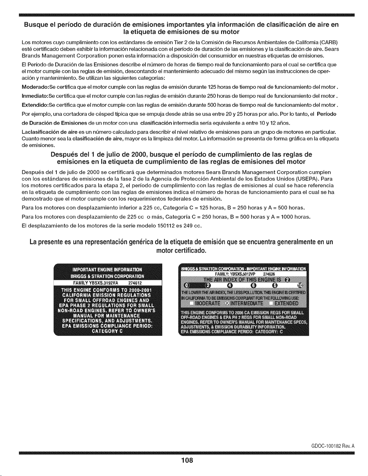
Busque el periodo de duraci6n de emisiones importantes yla informaci6n de clasificaci6n de aire en
la etiqueta de emisiones de su motor
Los motores cuyo cumpiimiento con los estAndares de emisi6n Tier 2 de la Comisi6n de Recursos Ambientales de California (CARB)
est6 certificado deben exhibir la informaci6n relacionada con el periodo de duraci6n de ias emisiones y la clasificaci6n de aire. Sears
Brands Management Corporation ponen esta informaci6n a disposici6n del consumidor en nuestras etiquetas de emisiones.
Ei Periodo de Duraci6n de las Emisiones describe el nQmero de horas de tiempo real de funcionamiento para el cuai se certifica que
el motor cumpie con ias reglas de emisi6n, descontando el mantenimiento adecuado del mismo segQn las instrucciones de oper-
aci6n y mantenimiento. Se utilizan las siguientes categonas:
Moderado:Se certifica que el motor cumpie con las reglas de emisi6n durante 125 horas de tiempo real de funcionamiento del motor.
Inmediato:Se certifica que el motor cumpie con las reglas de emisi6n durante 250 horas de tiempo real de funcionamiento del motor.
Extendido:Se certifica que el motor cumpie con las reglas de emisi6n durante 500 horas de tiempo real de funcionamiento del motor.
Por ejemplo, una cortadora de c6sped tJpica que se empuja desde arras se usa entre 20 y 25 horas por aSo. Por Io tanto, el Periodo
de Duraci6n de Emisiones de un motor con una clasificaci6n intermedia sena equivaiente a entre 10 y 12 aSos.
Laciasificaci6n de aire es un nQmero calculado para describir el nivel relativo de emisiones para un grupo de motores en particular.
Cuanto menor sea la clasificaci6n de aire, mayor es la limpieza del motor. La informaci6n se presenta de forma grAfica en la etiqueta
de emisiones.
Despu_s del 1 de julio de 2000, busque el periodo de cumplimiento de las reglas de
emisiones en la etiqueta de cumplimiento de las reglas de emisiones del motor
Despu6s del 1 de julio de 2000 se certificarA que determinados motores Sears Brands Management Corporation cumplen
con los estAndares de emisiones de la fase 2 de la Agencia de Protecci6n Ambientai de los Estados Unidos (USEPA). Para
los motores certificados para la etapa 2, el periodo de cumplimiento con ias reglas de emisiones al cual se hace referencia
en la etiqueta de cumplimiento con las reglas de emisiones indica el nQmero de horas de funcionamiento para el cual se ha
demostrado que el motor cumple con los requerimientos federales de emisi6n.
Para los motores con desplazamiento inferior a 225 cc, Categoria C = 125 horas, B = 250 horas y A = 500 horas.
Para los motores con desplazamiento de 225 cc o mAs, Categoria C = 250 horas, B = 500 horas y A = 1000 horas.
El desplazamiento de los motores de la serie modelo 150112 es 249 cc.
La presente es una representaci6n gen_rica de la etiqueta de emisi6n que se encuentra generaimente en un
motor certificado.
FAMILYYBSXS.3192VA 274812
GDOC-100182Rev.A
108
DECLARACION FEDERAL y/o DE CALIFORNIA SOBRE GARANTJAS EN EL CONTROL DE EIVIISIONES
SUS DERECHOS Y OBLIGACIONES EN CUANTO A LA GARANTJA
MTDConsumerGroupInc, laAgencia deProtecci6nMedioambientalde los EstadosUnidos(EPA),y para aquellosproductoscertificadosparasu ventaen el es-
tadode California,el Departamentode los Recursosdel Aire de California(CARB)secomplacenen explicarla garanfiaque cubre al sistemade control(ECS)de
emisiones(evaporativasy/o de escape)de su equipoy motor(motorde equipos de exteriores)de encendidopot chispaparatodo terreno,peque_o,de exteriores
del a_o2006 y a_osposterioresEn California,losnuevosmotoresde equipos de exterioresdebenestar dise_ados,construidosy equipadospara cumplircon las
estrictasnormasantipoluci6ndel Estado(en otrosestados,losequipos del a_o 1997y modelosposterioresdebenserestar dise_ados,construidosy equipados
para cumplircon las regulacionesdemotoresde encendidopor chispapara todoterrenopeque_osde laAgencia de Protecci6nMedioambientalde los Estados
Unidos,(EPA).MTDConsumerGroupInc. debe garantizarel sistemade controlde emisiones(ECS) desu motorde equipos de exteriorespot el periodode
tiempo indicadom_sabajo,siempreycuando no existausoincorrecto,negligenciao mantenimientoinadecuadode dicho motor.
Su ECSpuedeincluir piezastales como el carburador,el sistemade inyecci6nde combustible,el sistemade encendido,el convertidorcatalitico,losdep6sitos
de combustible,laslineas decombustible,lostaponesde combustible,lasv_lvulas, contenedores,filtros, manguerasde vapor,abrazaderas,conectoresyotros
componentesafinesrelacionadosconlas emisiones.
Dondeexista unacondici6ncubiertapor la garantia, MTDConsumerGroupInc. reparar_su motorde equiposde exterioressincosto alguno incluyendoel
diagn6stico,las piezasy la mano de obra.
COBERTURA DE LA GARANTJA DEL FABRICANTE:
Este sistemade controlde emisionesse garantizaporel t@minode dos aSos.Si algunapiezarelacionadacon lasemisionesde su motorde equiposde
exterioreses defectuosa,MTDCONSUMERGROUPINC.reparar_o sustituir_dichapieza.
RESPONSABILIDADES DEL PROPIETARIO SEGUN LA GARANTJA:
En su car_cterde propietariodel motordeequipos de exteriores,usted es responsabledel mantenimientorequeridoquese especificaen el manualdel propieta-
rio.MTDConsumerGroupInc le recomiendaque conservetodos losrecibos quecubrenel mantenimientode su motor,no obstanteIo cual MTDConsumerGroup
Inc nopodr_denegarel cumplimientode lagarantia Qnicamentepor lafaltade los recibos.
Comopropietariodel motorde equiposde exteriores,usteddebe saberqueMTDConsumerGroupInc. puededenegarlacoberturade la garantia si su motoro
unapieza del mismofallandebido a uso incorrecto,negligencia,mantenimientoindebidoo a modificacionesno aprobadas.
Ustedes responsablede presentarsu motoral centrode distribuci6no serviciotecnico de MTDConsumerGroupInc. tan prontocomo aparezcael problema.Las
reparacionescubiertaspor la garantiase debenIlevara caboen un lapso razonableque no excedade 30 dias. Sitiene alguna preguntarespectode lacobertura
de la garantia, p6ngaseen contactocon el Departamentodel ServicioT@nicode MTDConsumerGroupInc. al telefono1-800-800-7310o pot correoelectr6nico
en http://support.mtdproducts.com
COBERTURA DE LA GARANTJA DE EMISIONES GENERALES:
MTDConsumerGroupIncgarantizaal compradorfinal y a cadacompradorsubsiguienteque el motordeequiposde exteriores:est_ dise_ado,construidoy
equipadode modo de cumplir contodas las regulacionesaplicablesy quese encuentralibrede defectosde materialesyde fabricaci6nque pudierencausarla
falla deuna piezagarantizadaidentica,en todos losaspectos materialesa la pieza descriptaen la solicitudde certificaci6ndeMTDConsumerGroupInc.
El periodode garantiacomienzaen la fechade entregadel motoral compradorfinal o en lafecha en que la m_quinase pone en funcionamientopot primeravez.
El periodode garantiaes de dos aSos.
Sujetoa ciertas condicionesy exclusionesquese indicana continuaci6n,lagarantia delas piezas relacionadascon lasemisioneses la siguiente:
1. Cualquierpiezagarantizadaque no este programadaparaser reemplazadacomo partedel mantenimientorequeridoen lasinstruccionesescritassuminis-
tradasse garantizaporel periodo de garantiaarriba mencionado.Sila pieza falla duranteel periodo de coberturade lagarantia,la mismaser_ reparada
o reemplazadapor MTDConsumerGroupInc. deacuerdo con el parrafo(4) a continuaci6n.Cualquier piezareparadao reemplazadasegQnla garanfia se
garantizar_potel resto del periodode garantia.
2. Cualquierpiezagarantizadaqueeste programadasolamentepara inspecci6nregularen las instruccionesescritassuministradassegarantiza potel periodo
de garantia arribamencionado.Cualquierpiezareparadao reemplazadasegQnla garantiase garantizar_pot el restodel periodo.
3. Cualquierpiezagarantizadaqueeste programadapara reemplazosegL]nel mantenimientorequeridode conformidadcon lasinstruccionesescritassuminis-
tradas,se garantizaporel periodode tiempo anteriora laprimerafecha de reemplazoprogramadapara esa pieza.Si la piezafalla antes del primerreemplazo
programatic,la mismaser&reparadao reemplazadapot MTDConsumerGroupInc. deacuerdo con el parrafo(4) a continuaci6n.Cualquier piezareparadao
reemplazadabajogarantia se garantizar_potel resto del periodoanterioral primerreemplazoprogramaticpuntualparaesa pieza.
4. La reparaci6no el reemplazodecualquierpiezagarantizadade conformidadconlasdisposicionesde lagarantia queaquise estipulase deben realizaren un
centrode garantiasin costoalguno para el propietario.
5. Noobstantelas disposicionesque aqui se estipulan,losservicios o reparacionesbajo garantiase suministrar_nen todos nuestroscentrosde distribuci6nbajo
franquiciademantenimientopara los motoreso equiposen cuesti6n.
6. El propietariodel motorde equiposde exterioresno deber_pagarel trabajode diagn6sticodirectamenteasociadocon unapiezagarantizadadefectuosaen
relaci6ncon las emisiones,siempreycuandodicho trabajode diagn6sticose realiceen un centrocubiertopot lagarantia.
7. MTDConsumerGroupInces responsablepot daSoscausadosa otros componentesde motoreso equipos derivadosde lafalla bajo garantiadecualquier
piezagarantizada.
8. Durantelatotalidaddelperiododegarantiadelmotoryequipoparatodoterrenoarribamencionado,MTDConsumerGroupIncmantendr_unsuministro
depiezasbajogarantiasuficienteparasatisfacerlademandaesperadadetalespiezas.
9. Cualquierpiezadereemplazosepodr_usarparaelcumplimientodelmantenimientoolasreparacionesbajogarantiaysesuministrar_nsincargopara
elpropietario.Dichousonoreducir_lasobligacionesdegarantiadeMTDConsumerGroupInc.
10.Nosepodr_nusarpiezasadicionalesnimodificadasquenoestenexentasdeacuerdoconelDepartamentodelosRecursosdelAire(AirResourcesBoard).
Elusodecualquierpiezaadicionalomodificadanoexentaporelcompradorfinalser_causaldeinvalidezdelosreclamosbajogaranfia.MTDConsumer
GroupIncnotendr_responsabilidadpotlagarantiadefallasdepiezasgarantizadasquefuerencausadaspotelusodeunapiezaadicionalnoexenta
omodificada.
PIEZAS GARANTIZADAS:
La reparaci6no el reemplazodecualquierpieza garantizadaquede otto modo pudieseestar cubiertapor lagarantia podr_set excluidade tal coberturade
garantiasi MTDConsumerGroupIncdemuestraqueel motores objeto de usoincorrecto,negligenciao mantenimientoinadecuado,y que tal uso incorrecto,
negligenciao mantenimientoinadecuadofuecausa directade la necesidadde reparaci6no reemplazode dichapieza.NoobstanteIo antedicho,cualquierajuste
de un componentecon undispositivode limitaci6nde ajusteinstaladoen f_brica y quefuncioneadecuadamente,podr_set cubiertopot la garantia.Adem_s,
la coberturabajo esta garantiase extiendesolo a piezasqueestuvieronpresentesen el motory equipotodo terrenoadquiridos.
Est_ncubiertaslas siguientespiezascon garanfia para emisiones(decorresponder):
(1) Sistemademedici6nde combustible
• Sistemade mejorapara inicioen frio (cebadosuave)
• Carburadory piezasinternas(osistemade inyecci6npot combustible)
• Bombade combustible
• Dep6sitode combustible
(2) Sistemade inducci6nde aire
• Purificadordeaire
• Colectordeadmisi6n
(3) Sistemade encendido
• Bujia(s) deencendido
• Sistemade encendidopot magneto
(4) Sistemade encendido
• Convertidorcatalitico
,, SAI (v_lvula Reed)
(5) Componentesvariosutilizadosen el sistemaanterior
• Wlvulas e interruptoresde vacio,temperatura,posici6nsensiblesal tiempo
• Conectoresy montajes
(6) Controlevaporativo
• Manguerade combustible
• Abrazaderasde la manguerade combustible
• Tap6ndel combustibleatadopot correa
• Cajadecarbono
• Lineas de vapor
GDOC-100223

Felicitaciones por haber realizado una adquisici6n inteligente. El producto Craftsman® que ha
adquirido esta diseSado y fabricado para brindar muchos aSos de funcionamiento confiable. Pero
como todos los productos a veces puede requerir de reparaciones. Es en ese momento cuando el
disponer de un Acuerdo de protecci6n para reparaciones le puede ahorrar dinero y problemas.
A continuaci6n se detallan los puntos incluidos en el Acuerdo:
[] Servicio experto prestadopor nuestros 10,000 especialistas en reparaciones profesionales
[] Servicio ilirnitado sin cargo para las piezasy la mano de obra en todas las reparacionescubiertas
[] Reernplazo del producto hasta 1500 d61aressi no es posible reparar el producto cubierto
[] Descuento de 25% del precio normal del servicio y de las piezas relacionadas con el mismo que no esten cubiertas
por el acuerdo; ademas, 25% del precio normal de laverificaci6n de mantenimientopreventivo
[] Ayuda r_pida pot tel_fono - Io IlamamosResoluci6n RApida- el apoyo telef6nico de un Chamusca al representante.
Piense en nosotros como el manual "de un dueSohablador."
Una vez adquirido el Acuerdo, puede programar el servicio con tan s61orealizar una Ilamadatelef6nica. Puede Ilamar en
cualquier momento del dia o de la noche o programar un servicio en linea.
ElAcuerdo de Protecci6nde Reparaci6nes una compra sin riesgo. Si usted anula por alguna raz6n durante el periodo de
garantia de producto, proporcionaremos un reembolso Ileno.O, un reembolso prorrateadoen cualquier momento despues
del periodo de garantia de producto expira, iAdquiera hoy su acuerdode protecci6n para reparaciones!
Se aplican determinadas limitaciones y exclusiones. Para obtener informaciTn adicional y precios en los Estados
Unidos Ilame al 1-800-827-6655.
El *Coverage en Canad_ivaria en algunos articulos. Para detalles Ilenos la Ilamada Chamusca Canad_ien 1-800-
361-8885.
Servicio de instalaci6n de Sears
Si desea solicitar la instalaci6n profesional de Sears de aparatos domesticos, dispositivos paraabrir portones, calentado-
res de agua y otros articulos domesticos importantes, en los Estados Unidos o Canada flame al 1-800-4-MY-HOME®.
111

Riding Equipment
questions or problems?
Satisfaction with your purchase
is our number one concern!
To troubleshoot problems,
get answers to questions, order parts,
or schedule repair service for your
Riding Equipment, call the number below.
Para respuestas a preguntas o problemas,
y ordenar piezas o pedir servicio para la
reparacibn de su equipo, Ilame el nt_mero abajo.
1-800-659-5917
Craftsman Help Line
www.craftsman.com
TM
® Registered Trademark / Trademark of KCD IP, LLC in the United States, or Sears Brands, LLC in other countries
® Marca Registrada / TMMarca de Fabrica de KCD IP, LLC en Estados Unidos, o Sears Brands, LLC in otros paises