Loading ...
Loading ...
Loading ...
64
Single Zone High Efciency, Standard, Extended Pipe and Mega Wall Mount Installation Manual
Due to our policy of continuous product innovation, some specifications may change without notification.
©LG Electronics U.S.A., Inc., Englewood Cliffs, NJ. All rights reserved. “LG” is a registered trademark of LG Corp.
ELECTRICAL WIRING
Power Supply / Power Wiring Specifications
• Single Zone systems operate at 1Ø, 208-230V, 60Hz, with the exception of Mega 115V, which operates at 1Ø, 115V, 60Hz.
• Power supply, wire type and size should be selected based on National Electrical Code and local codes. Maximum allowable voltage fluctua-
tion ±10% or nameplate rated value. Refer to Figure 77 for wiring guidelines.
• Properly ground the Single Zone outdoor unit and indoor unit per National Electrical Code and local codes.
• Use only copper wiring that is stranded and shielded with the wires separately insulated.
• Ground wire should be longer than the common power/communication wires.
• Refer to the inside of the Chassis Cover for Circuit and Terminal Block Diagrams for your model unit.
• Always match color codes of each wire and follow wiring diagram.
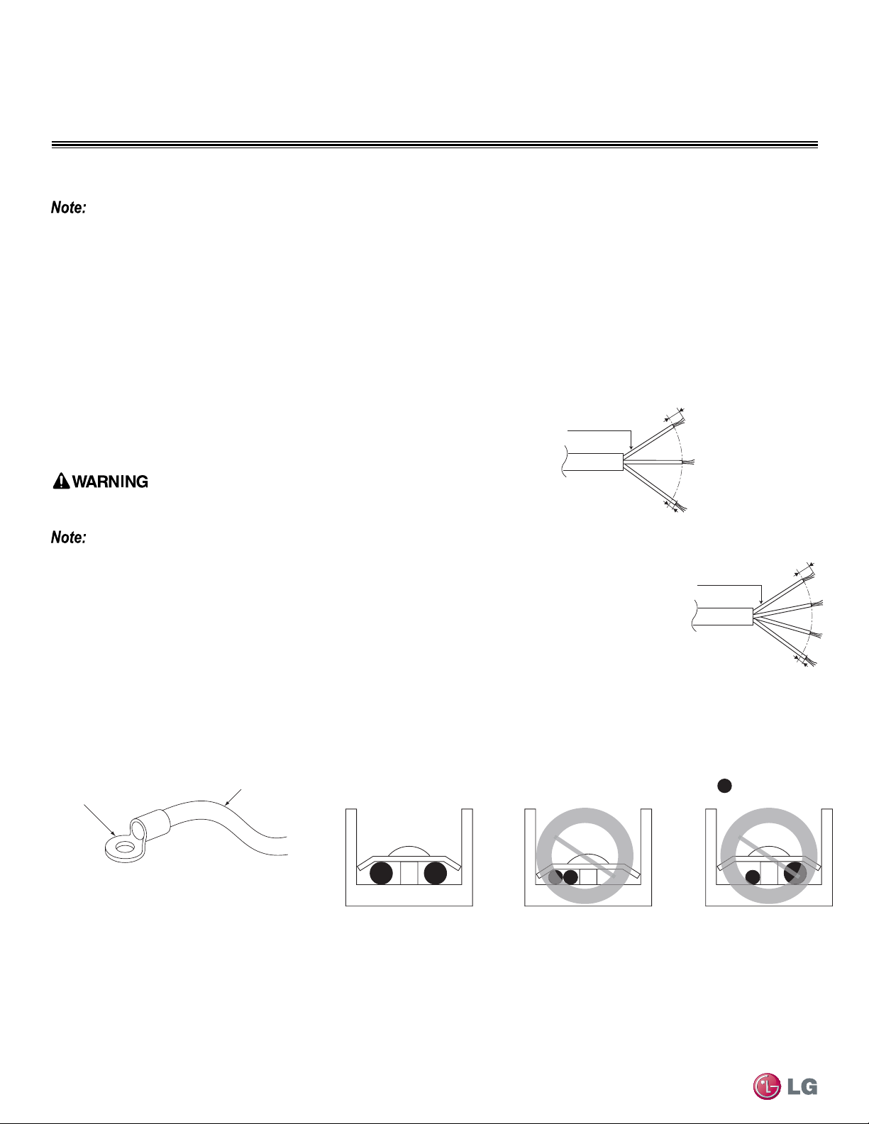
Figure 77: Single Zone Outdoor and Indoor Wiring
and Communications Cable Diagram
:Copper Wire
Terminate multiple power wires of
the same gauge to both sides.
Do not terminate two wires on
one side.
Do not terminate different gauge
wires to a terminal block.
Ring Terminal
Power Wiring
Connecting the Power Wiring Guidelines
Best practice dictates using ring or spade terminals to terminate power wiring at the
power terminal block (Figure 78).
If ring terminals or spade clips are not available, then:
Do not terminate different gauge wires to the power terminal block. Slack in the wiring may
generate heat and re.
• When terminating wires of the same thickness, follow the instructions demonstrated
in the illustrations below at Figure 79.
• Firmly attach the wire; secure in a way to prevent external forces from being impart-
ed on the terminal block.
• Use an appropriately sized screwdriver for tightening the terminals.
• Do not over tighten the connections; overtightening may damage the terminals.
Figure 78: Close up of a Typical Ring Terminal
Figure 79: Proper and Improper Power Wiring Connections
Power Wiring Specications and Best Practices
6/16” ± 2/16”
13/16”
GN/YL
AWG_“A”
Power Wiring, Ground
to Outdoor Unit
Power Wiring, Ground,
Communication Cable
From Outdoor Unit
To Indoor Unit
13/16”
GN/YL
AWG_“B”
Line Voltage
(208/230V)
GN/YL = (Ground, Yellow)
6/16” ± 2/16”
Loading ...
Loading ...
Loading ...