
SINGLE ZONE HIGH EFFICIENCY, STANDARD,
EXTENDED PIPE, AND MEGA WALL MOUNTED
INSTALLATION MANUAL
Single Zone High Efciency:
LS091HSV3, LS121HSV3, LS181HSV3, LS240HSV3
Single Zone Standard: LS307HV3, LS360HV3
Single Zone Extended Pipe: LS240HLV, LS300HLV, LS360HLV
Single Zone Mega: LS090HEV, LS120HEV, LS180HEV, LS240HEV
Single Zone Mega 115V: LS090HXV, LS120HXV

The instructions included in this manual must be followed to prevent product malfunction, property damage, injury, or death to the user or
other people. Incorrect operation due to ignoring any instructions will cause harm or damage. The level of seriousness is classified by the
symbols described below.
Do not throw away, destroy, or lose this manual.
Please read carefully and store in a safe place for future reference.
Content familiarity required for proper installation.
A summary list of safety precautions begins on page 3.
For more technical materials such as submittals, engineering
databooks, and catalogs, visit www.lghvac.com.
For continual product development, LG Electronics U.S.A., Inc., reserves the right to change specifications without notice.
©LG Electronics U.S.A., Inc.
This document, as well as all reports, illustrations, data, information, and other materials are the property of LG Electronics U.S.A., Inc.
PROPRIETARY DATA NOTICE
This document, as well as all reports, illustrations, data, information, and
other materials are the property of LG Electronics U.S.A., Inc., and are
disclosed by LG Electronics U.S.A., Inc., only in confidence.
This document is for design purposes only.
IM-WallMounted-ALL-08-14
3
Safety Instructions
Due to our policy of continuous product innovation, some specifications may change without notification.
©LG Electronics U.S.A., Inc., Englewood Cliffs, NJ. All rights reserved. “LG” is a registered trademark of LG Corp.
SAFETY INSTRUCTIONS
The instructions below must be followed to prevent product malfunction, property damage, injury or death to the user or other people. Incor-
rect operation due to ignoring any instructions will cause harm or damage. The level of seriousness is classified by the symbols described
below.
INSTALLATION
TABLE OF SYMBOLS
This symbol indicates an imminently hazardous situation which, if not avoided, will result in death or serious
injury.
This symbol indicates a potentially hazardous situation which, if not avoided, could result in death or serious
injury.
This symbol indicates a potentially hazardous situation which, if not avoided, may result in minor or
moderate injury.
This symbol Indicates situations that may result in equipment or property damage accidents only.
This symbol indicates an action should not be completed.
Do not install, remove, or re-install the unit by yourself
(customer). Ask the dealer or an authorized technician to
install the unit.
Improper installation by the user may result in water leakage, re,
explosion, electric shock, physical injury or death.
For replacement of an installed unit, always contact an
authorized LG service provider.
There is risk of re, electric shock, explosion, and physical injury or death.
The unit is shipped with refrigerant and the service valves
closed. Do not open service valves on the unit until all
non-condensible have been removed from the piping system
and authorization to do so has been obtained from the com-
missioning agent.
There is a risk of equipment damage, refrigerant contamination, refriger-
ant loss, physical injury or death.
Be very careful when transporting the product.
• Do not attempt to carry the product without assistance.
• Some products use polypropylene bands for packaging. Do not use
polypropylene bands to lift the unit.
• Suspend the unit from the base at specified positions.
• Support the unit a minimum of four points to avoid slippage from
rigging apparatus.
Wear protective gloves when handling equipment. Sharp
edges may cause personal injury.
The unit is shipped with refrigerant and service valves
closed. Do not run the compressor with the service valves
closed.
There is a risk of equipment damage, explosion, physical injury, or death.
Dispose the packing materials safely.
• Packing materials, such as nails and other metal or wooden parts,
may cause puncture wounds or other injuries.
• Tear apart and throw away plastic packaging bags so that children
may not play with them and risk suffocation and death.
Install the unit considering the potential for strong winds or
earthquakes.
Improper installation may cause the unit to fall over, resulting in physical
injury or death.
If the air conditioner is installed in a small space, take
measures to prevent the refrigerant concentration from
exceeding safety limits in the event of a refrigerant leak.
Consult the latest edition of ASHRAE (American Society of Heating,
Refrigerating, and Air Conditioning Engineers) Standard 15. If the
refrigerant leaks and safety limits are exceeded, it could result in personal
injuries or death from oxygen depletion.
Install the unit in a safe location where nobody can step on or
fall onto it.
There is risk of unit damage, physical injury or death.
Do not install the unit on a defective stand.
There is a risk of property damage or physical injury.
Install the drain hose to ensure adequate drainage.
There is a risk of water leakage and property damage.
4
Single Zone High Efciency, Standard, Extended Pipe and Mega Wall Mount Installation Manual
Due to our policy of continuous product innovation, some specifications may change without notification.
©LG Electronics U.S.A., Inc., Englewood Cliffs, NJ. All rights reserved. “LG” is a registered trademark of LG Corp.
SAFETY INSTRUCTIONS
Don’t store or use ammable gas / combustibles near the unit.
There is risk of product failure, re, explosion, and physical injury or death.
It may result in an accident that causes product damage or personal injury
or death.
Periodically check that the outdoor frame is not damaged.
There is a risk of equipment damage, explosion, physical injury, or death.
Do not change the settings of the protection devices.
If the pressure switch, thermal switch, or other protection device is
shorted and forced to operate improperly, or parts other than those
specied by LG are used, there is risk of re, electric shock, explosion,
and physical injury or death.
Replace all control box and panel covers.
If cover panels are not installed securely, dust, water and animals may
enter the water source unit, causing re, electric shock, and physical in-
jury or death.
Always check for system refrigerant leaks after the unit has
been installed or serviced.
Low refrigerant levels may cause product failure, and exposure to high
concentration levels of refrigerant gas may lead to illness or death. Keep
the unit upright during installation to avoid vibration or water leakage.
Don’t install the unit where it’s directly exposed to ocean winds.
Ocean winds may cause corrosion, particularly on the condenser and
evaporator ns, which, in turn could cause product malfunction or inef-
cient performance.
When installing the unit in a low-lying area, or a location that
is not level, use a raised concrete pad or concrete blocks to
provide a solid, level foundation.
This may prevent water damage and reduce abnormal vibration.
Properly insulate all cold surfaces to prevent “sweating.”
Cold surfaces such as uninsulated piping can generate condensate that
may drip and cause a slippery oor condition and / or water damage to
walls.
When installing the unit in a hospital, mechanical room, or
similar electromagnetic eld (EMF) sensitive environment,
provide sufcient protection against electrical noise.
Inverter equipment, power generators, high-frequency medical equip-
ment, or radio communication equipment may cause the air conditioner to
operate improperly. The unit may also affect such equipment by creating
electrical noise that disturbs medical treatment or image broadcasting.
Do not use the product for special purposes such as
preserving foods, works of art, wine coolers, or other
precision air conditioning applications. The equipment is
designed to provide comfort cooling and heating.
There is risk of property damage.
Do not make refrigerant substitutions. Use R410A only.
If a different refrigerant is used, or air mixes with original refrigerant, the
unit will malfunction and be damaged.
When connecting refrigerant tubing, remember to allow for
pipe expansion.
Improper piping may cause refrigerant leaks and system malfunction.
Do not install the unit in a noise sensitive area.
Take appropriate actions at the end of HVAC equipment life
to recover, recycle, reclaim or destroy R410A refrigerant
according to applicable U.S. Environmental Protection
Agency (EPA) rules.
INSTALLATION - CONTINUED
5
Safety Instructions
Due to our policy of continuous product innovation, some specifications may change without notification.
©LG Electronics U.S.A., Inc., Englewood Cliffs, NJ. All rights reserved. “LG” is a registered trademark of LG Corp.
SAFETY INSTRUCTIONS
High voltage electricity is required to operate this system.
Adhere to the National Electrical Codes and these
instructions when wiring.
Improper connections and inadequate grounding can cause accidental
injury or death.
Always ground the unit following local, state, and National
Electrical Codes.
Turn the power off at the nearest disconnect before servicing
the equipment.
Electrical shock can cause physical injury or death.
Properly size all circuit breakers or fuses.
There is risk of re, electric shock, explosion, physical injury or death.
The information contained in this manual is intended for use
by an industry-qualied, experienced, certied electrician
familiar with the U.S. National Electric Code (NEC) who is
equipped with the proper tools and test instruments.
Failure to carefully read and follow all instructions in this manual can
result in equipment malfunction, property damage, personal injury or death.
All electric work must be performed by a licensed electrician
and conform to local building codes or, in the absence of
local codes, with the National Electrical Code, and the
instructions given in this manual.
If the power source capacity is inadequate or the electric work is not per-
formed properly, it may result in re, electric shock, physical injury or death.
Refer to local, state, and federal codes, and use power wires
of sufcient current capacity and rating.
Wires that are too small may generate heat and cause a re.
Secure all eld wiring connections with appropriate wire
strain relief.
Improperly securing wires will create undue stress on equipment power
lugs. Inadequate connections may generate heat, cause a re and phys-
ical injury or death.
WIRING
6
Single Zone High Efciency, Standard, Extended Pipe and Mega Wall Mount Installation Manual
Due to our policy of continuous product innovation, some specifications may change without notification.
©LG Electronics U.S.A., Inc., Englewood Cliffs, NJ. All rights reserved. “LG” is a registered trademark of LG Corp.
SAFETY INSTRUCTIONS
Do not provide power to or operate the unit if it is ooded or
submerged.
There is risk of re, electric shock, physical injury or death.
Use a dedicated power source for this product.
There is risk of re, electric shock, physical injury or death.
Do not operate the disconnect switch with wet hands.
There is risk of re, electric shock, physical injury or death.
Periodically verify the equipment mounts have not
deteriorated.
If the base collapses, the unit could fall and cause property damage,
product failure, physical injury or death.
If gas leaks out, ventilate the area before operating the unit.
Leaking gas may cause re, electric shock, explosion, physical injury or
death if the unit is mounted in an enclosed, low-lying, or poorly ventilated
area and the system develops a refrigerant leak.
Do not allow water, dirt, or animals to enter the unit.
There is risk of unit failure, re, electric shock, physical injury or death.
Avoid excessive cooling and periodically perform ventilation
to the unit.
Inadequate ventilation is a health hazard.
Do not touch the refrigerant piping during or after operation.
It can cause burns or frostbite.
Do not operate the unit with the panel(s) or protective
cover(s) removed; keep ngers and clothing away from
moving parts.
The rotating, hot, cold, and high-voltage parts of the unit can cause
physical injury or death.
Periodically, check power cord and plug for damage.
Cord must be replaced by the manufacturer, its service agent, or similar
qualied persons in order to avoid physical injury and / or electric shock.
Do not open the inlet grille of the unit during operation. Do
not operate the unit with the panels or guards removed. Do
not insert hands or other objects through the inlet or outlet
with the unit is plugged in. Do not touch the electrostatic
lter, if the unit includes one.
The unit contains sharp, rotating, hot, and high voltage parts that can
cause personal injury and / or electric shock.
To avoid physical injury, use caution when cleaning or
servicing the air conditioner.
Clean up the site after installation is nished, and check that no metal scraps,
screws, or bits of wiring have been left inside or surrounding the unit.
Do not use this equipment in mission critical or special-
purpose applications such as preserving foods, works of art,
wine coolers or refrigeration. The equipment is designed to
provide comfort cooling and heating.
Oil, steam, sulfuric smoke, etc., can signicantly reduce the performance
of the unit, or damage its parts.
Provide power to the compressor crankcase heaters at least
six (6) hours before operation begins.
Starting operation with a cold compressor sump(s) may result in severe
bearing damage to the compressor(s). Keep the power switch on during
the operational season.
Do not block the inlet or outlet.
Unit may malfunction.
Securely attach the electrical part cover to the indoor unit
and the service panel to the outdoor unit.
Non-secured covers can result in re or electric shock due to dust or water.
OPERATION

7
Due to our policy of continuous product innovation, some specifications may change without notification.
©LG Electronics U.S.A., Inc., Englewood Cliffs, NJ. All rights reserved. “LG” is a registered trademark of LG Corp.
TABLE OF CONTENTS
Safety Instructions ................................................................................ 3
General Data ..........................................................................................8
Unit Nomenclature ...............................................................................8
Single Zone High Effi ciency Unit Specifi cations ..................................9
Single Zone Standard Unit Specifi cations ..........................................11
Single Zone Extended Pipe Unit Specifi cations ................................ 13
Single Zone Mega Unit Specifi cations ..........................................15-18
Single Zone Mega115V Unit Specifi cations ....................................... 19
Electrical ............................................................................................21
R410A Refrigerant .............................................................................22
General Installation Guidelines ..........................................................23
Location Selection .............................................................................23
Oceanside Applications ..................................................................... 24
Mounting Bolt Location ......................................................................25
Required Clearances .........................................................................26
Mounting of Indoor Unit Installation Plate .....................................27-31
Mounting of Indoor Unit .....................................................................32
Piping Preparation .............................................................................33
Piping Materials and Handling ......................................................35-39
Piping Support, Elbow Usage ............................................................40
Refrigerant Piping System Layout .....................................................41
Refrigerant Piping Connections .........................................................42
Refrigerant Piping System Limitations ...............................................42
Installation Overview .........................................................................44
Directional Pipe Formation ................................................................45
Drain Hose .........................................................................................46
Outdoor Unit Connections ............................................................47-51
Indoor Unit Connections ....................................................................52
Indoor Unit Connections - Conduit Bracket Placement .....................53
Bundling and Cutting Line .................................................................54
Refrigerant Piping Insulation ........................................................55-57
Air Purging .........................................................................................58
Leak Test/Soap Method Check ..........................................................59
Evacuation of Lines ...........................................................................60
Finishing Up .......................................................................................60
Remote Controller .............................................................................61
Pump Down, Cooling Only Mode ......................................................62
Electrical Wiring ..................................................................................63
General Information and Safety Guidelines .......................................63
Power Wiring Specifi cations and Best Practices ...............................64
Controllers ......................................................................................... 66
Indoor Unit Electrical Connections ...............................................67-71
Outdoor Unit Electrical Connections .............................................72-75
Self Diagnosis Functions ..................................................................76
LG SIMS - Self Diagnosis Functions ................................................78
Troubleshooting .................................................................................. 80
Error Codes .................................................................................80-82
Refrigerant Leaks ..............................................................................83
Installation Checklist ...........................................................................84
8
Single Zone High Efciency, Standard, Extended Pipe and Mega Wall Mount Installation Manual
Due to our policy of continuous product innovation, some specifications may change without notification.
©LG Electronics U.S.A., Inc., Englewood Cliffs, NJ. All rights reserved. “LG” is a registered trademark of LG Corp.
GENERAL DATA
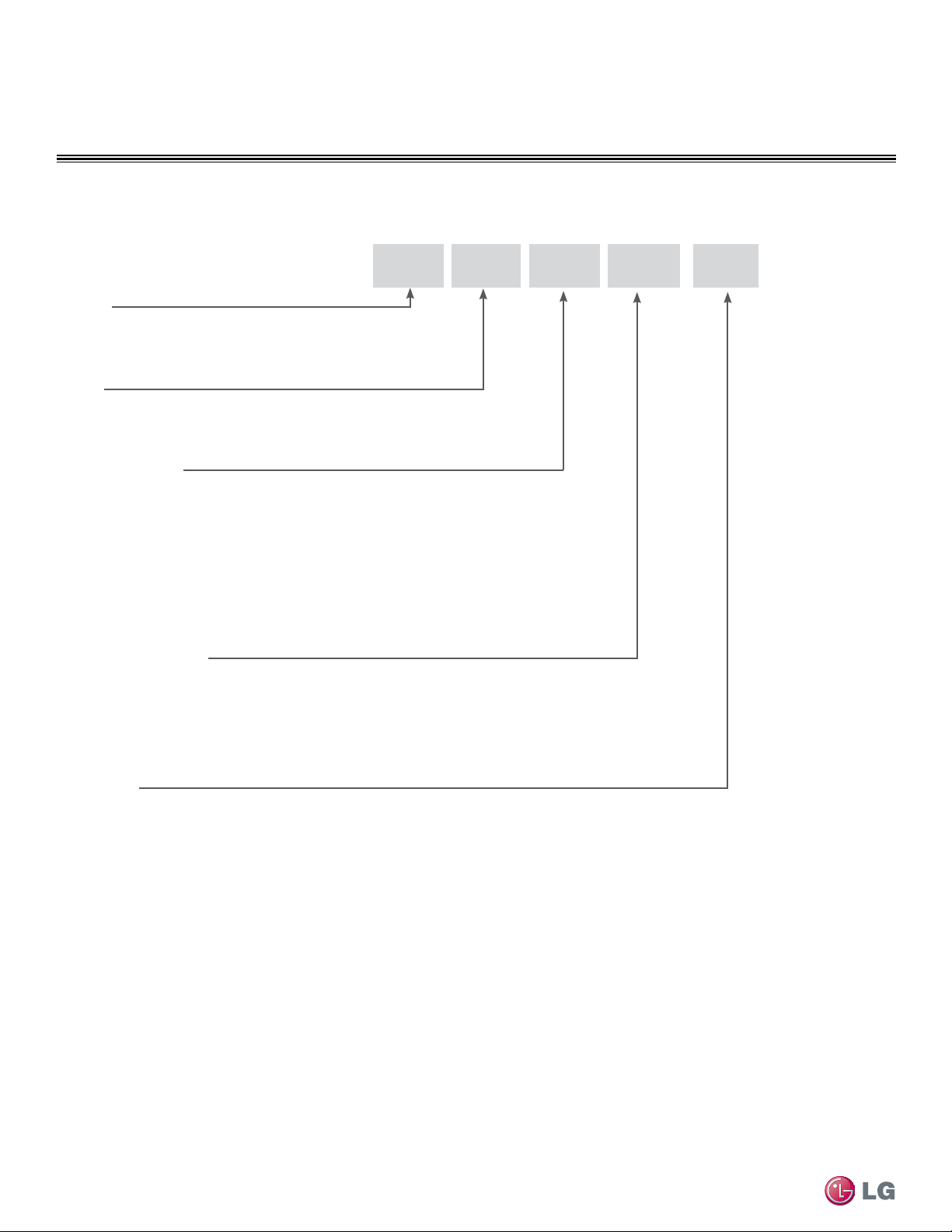
Single Zone Wall Mount Indoor and Outdoor Units
LS
N 091 HSV 3
Generation
3 = Third
Indoor/Outdoor Product
HSV = High Efficiency
HV = Standard
HLV = Extended Pipe
HEV = Mega
HXV = Mega 115V
Nominal Capacity
(Nominal cooling capacity in Btu/h)
090/091 = 9,000
120/121 = 12,000
180/181 = 18,000
240 = 24,000
300/307 = 30,000
360 = 36,000
Type
N = Indoor Wall Mount Unit
U = Outdoor Heat Pump Unit
Family
LS= High Efficiency Wall Mount / Standard/ / Extended Pipe / Mega
Unit Nomenclature
9
Product Data
Due to our policy of continuous product innovation, some specifications may change without notification.
©LG Electronics U.S.A., Inc., Englewood Cliffs, NJ. All rights reserved. “LG” is a registered trademark of LG Corp.
GENERAL DATA
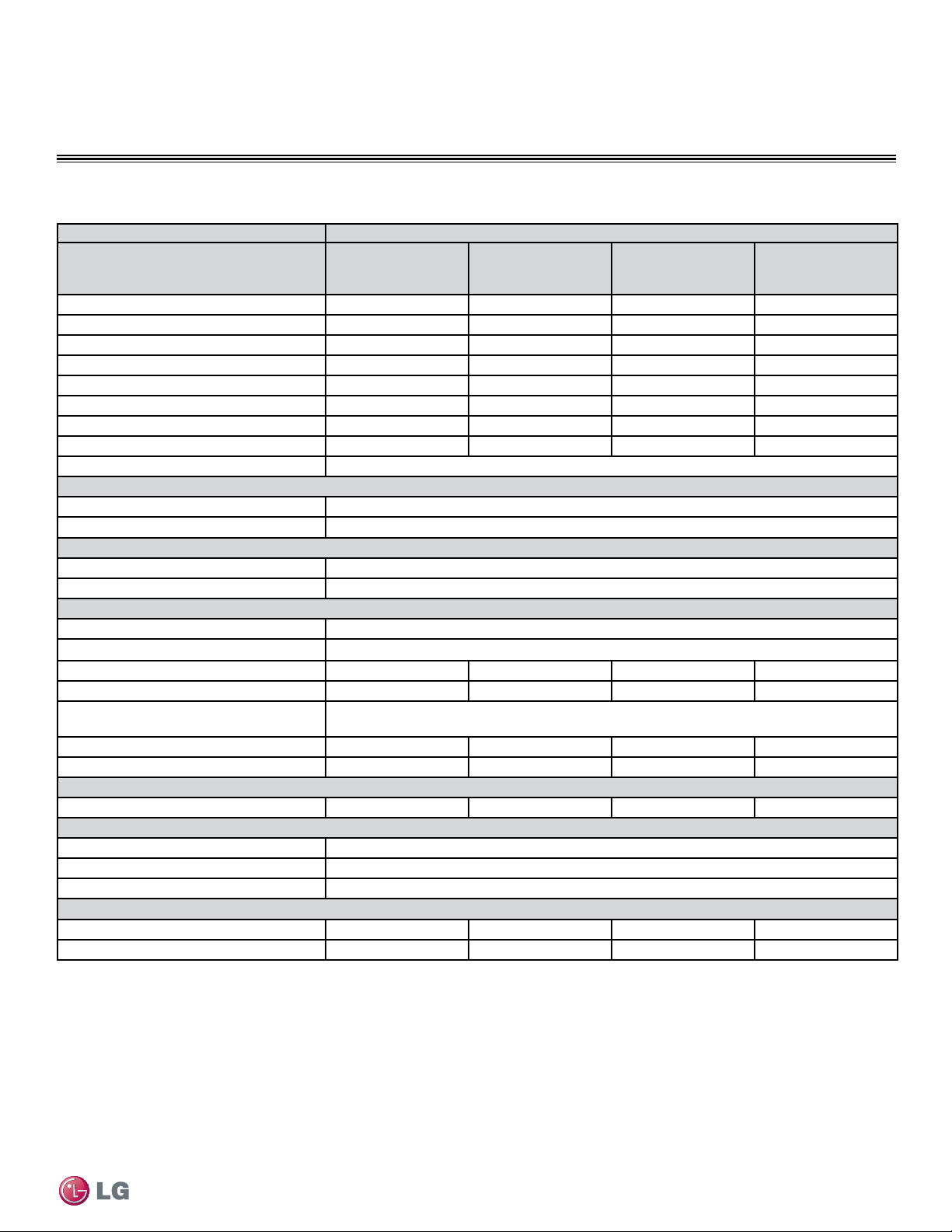
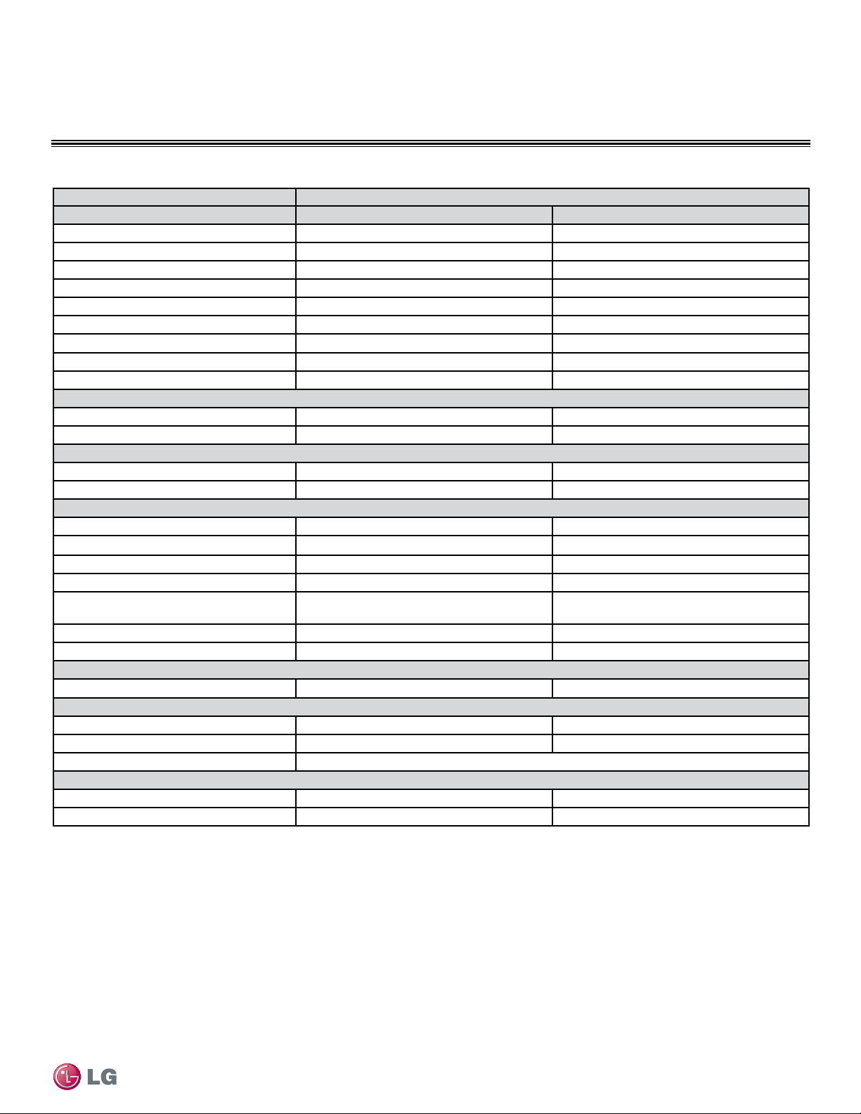
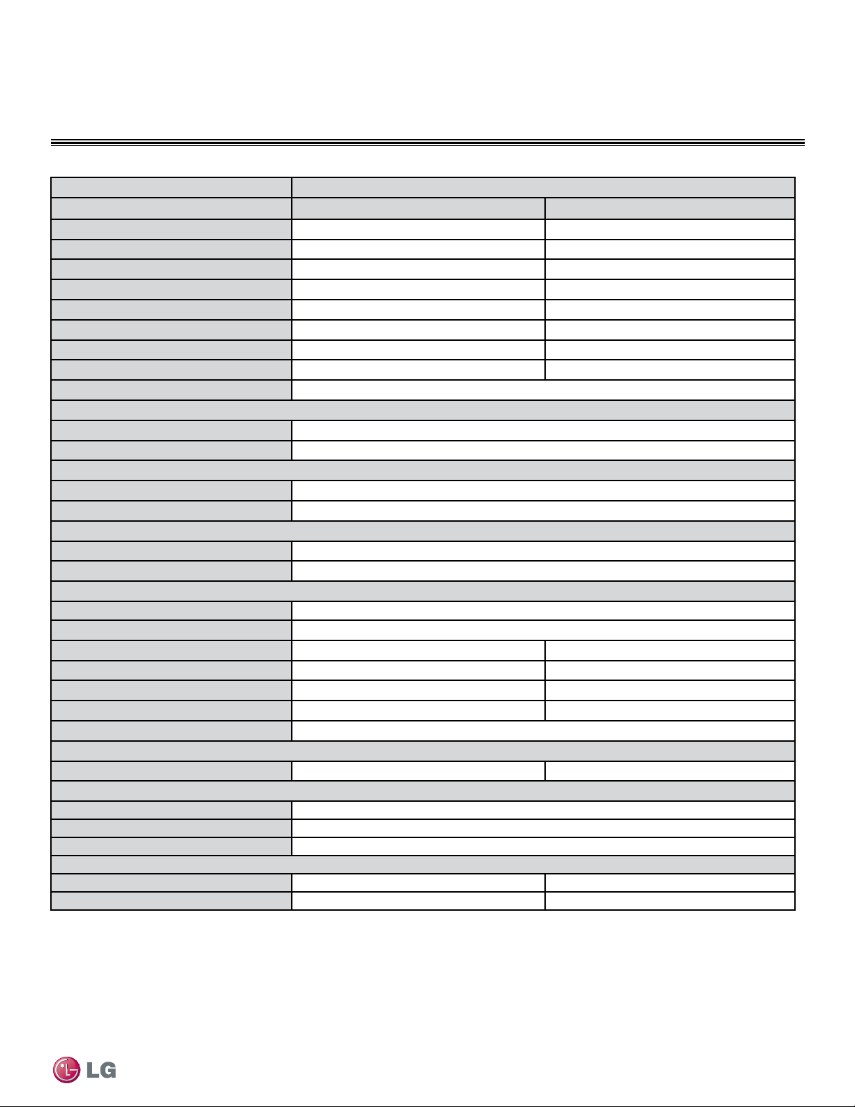
Single Zone High Efciency Unit Specications
Type Single Zone High Efciency Units
System Model Number (IDU/ODU)
LS091HSV3
(LSN091HSV3/
LSU091HSV3)
LS121HSV3
(LSN121HSV3/
LSU121HSV3)
LS181HSV3
(LSN181HSV3/
LSU181HSV3)
LS240HSV3
(LSN240HSV3/
LSU240HSV3)
Nominal Cooling Capacity (Btu/h)
9,000 11,200 18,200 22,000
Cooling Power Input
1
(kW)
0.67 0.89 1.4 1.7
Nominal Heating Capacity (Btu/h)
1
10,800 13,300 22,000 27,600
Heating Power Input
1
(kW)
0.70 1.0 1.7 2.3
COP
4.53 3.90 3.66 3.4
EER
13.3 12.5 12.6 12.5
SEER
21.5 21.5 20.5 20.0
HSPF
11.0 11.0 9.7 10.2
Power Supply (V/Hz/Ø)
208-230/60/1
Outdoor Unit Operating Range
2
Cooling (°F DB)
14-118
Heating (°F WB)
-4-75
Indoor Unit Operating Range
2
Cooling (°F)
64-90
Heating (°F)
60-86
Unit Data
Refrigerant Type
3
R410A
Refrigerant Control
EEV
IDU Sound Pressure
4
dB(A) (H/M/L)
38/33/24 39/33/24 45/40/35 46/43/39
ODU Sound Pressure
4
dB(A)
45 45 53 54
Power/Communication Cable
5
(No. x AWG)
4 x 18
IDU Net/Shipping Weight (lbs)
23/28 23/28 32/41 36/42
ODU Net/Shipping Weight (lbs)
75/79 75/79 123/131 128/137
Compressor
Compressor Type (Qty)
Rotary (1) Rotary (1) Twin Rotary (1) Twin Rotary (1)
Fan
IDU Type (Qty)
Cross Flow (1)
ODU Type (Qty)
Propeller (1)
Motor/Drive
Brushless Digitally Controlled/Direct
Airflow Rate
IDU Max/H/M/L (CFM)
388/335/272/212 423/353/272/212 735/622/509/399 883/742/629/424
ODU Max (CFM)
1,165 1,165 2,119 2,119
Table 1: Single Zone High Efciency Unit Specications
EEV: Electronic Expansion Valve IDU: Indoor Unit ODU: Outdoor Unit
1
Power Input is rated at high speed.
2
Low Ambient Wind Baffle Kit allows operation down to 0°F in cooling mode.
3
Take appropriate actions at the end of HVAC equipment life to recover, recycle, reclaim or destroy R410A
refrigerant according to applicable regulations (40 CFR Part 82, Subpart F) under section 608 of CAA.
4
Sound Pressure levels are tested in an anechoic chamber under ISO Standard 1996.
5
All power/communication cables to be minimum 18 AWG, 4-conductor, stranded, shielded and must
comply with applicable and national code.
Power wiring is field supplied and must comply with the applicable local and national codes.
This unit comes with a dry helium charge.
This data is rated 0 ft above sea level with 24.6 of refrigerant line per indoor unit and a 0 ft level
difference outdoor and indoor units.
Cooling capacity rating obtained with air entering the indoor unit at 80ºF dry bulb (DB) and 67ºF wet bulb
(WB) and outdoor ambient conditions of 95ºF dry bulb (DB) and 75ºF wet bulb (WB).
Heating capacity rating obtained with air entering the indoor unit at 70ºF dry bulb (DB) and 59ºF wet bulb
(WB) and outdoor ambient conditions of 47ºF dry bulb (DB) and 43ºF wet bulb (WB).
10
Single Zone High Efciency, Standard, Extended Pipe and Mega Wall Mount Installation Manual
Due to our policy of continuous product innovation, some specifications may change without notification.
©LG Electronics U.S.A., Inc., Englewood Cliffs, NJ. All rights reserved. “LG” is a registered trademark of LG Corp.
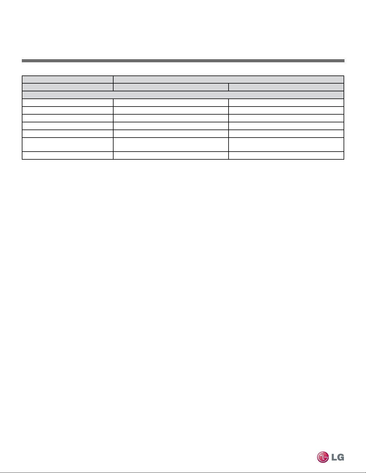
GENERAL DATA
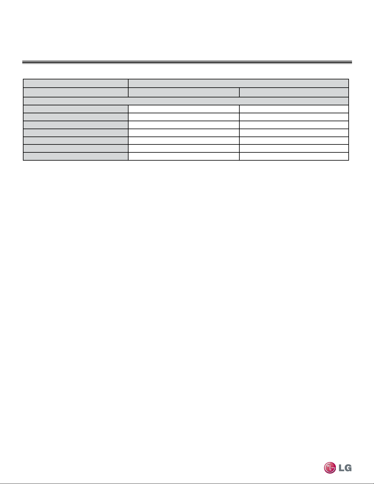
Type Single Zone High Efciency Units
System Model Number (IDU/ODU)
LS091HSV3
(LSN091HSV3/
LSU091HSV3)
LS121HSV3
(LSN121HSV3/
LSU121HSV3)
LS181HSV3
(LSN181HSV3/
LSU181HSV3)
LS240HSV3
(LSN240HSV3/
LSU240HSV3)
Piping
Liquid Line (in, OD)
1/4 1/4 3/8 3/8
Vapor Line (in, OD)
3/8 3/8 5/8 5/8
Condensation Line (OD, ID)
27/32, 5/8 27/32, 5/8 27/32, 5/8 27/32, 5/8
Additional Refrigerant Charge (oz/ft)
0.22 0.22 0.38 0.38
Max Pipe Length
6
(ft)
65.6 65.6 98.4 98.4
Piping Length
6
(no add’l
refrigerant, ft)
41.0 41.0 24.6 24.6
Max Elevation Difference (ft)
32.8 32.8 49.2 49.2
Table 1: Single Zone High Efciency Unit Specications - Continued
EEV: Electronic Expansion Valve IDU: Indoor Unit ODU: Outdoor Unit
6
Piping lengths are equivalent.
Power wiring is field supplied and must comply with the applicable local and national codes.
This unit comes with a dry helium charge.
This data is rated 0 ft above sea level with 24.6 of refrigerant line per indoor unit and a 0 ft level
difference outdoor and indoor units.
Cooling capacity rating obtained with air entering the indoor unit at 80ºF dry bulb (DB) and 67ºF wet
bulb (WB) and outdoor ambient conditions of 95ºF dry bulb (DB) and 75ºF wet bulb (WB).
Heating capacity rating obtained with air entering the indoor unit at 70ºF dry bulb (DB) and 59ºF wet
bulb (WB) and outdoor ambient conditions of 47ºF dry bulb (DB) and 43ºF wet bulb (WB).
Single Zone High Efciency Unit Specications
11
Product Data
Due to our policy of continuous product innovation, some specifications may change without notification.
©LG Electronics U.S.A., Inc., Englewood Cliffs, NJ. All rights reserved. “LG” is a registered trademark of LG Corp.
GENERAL DATA
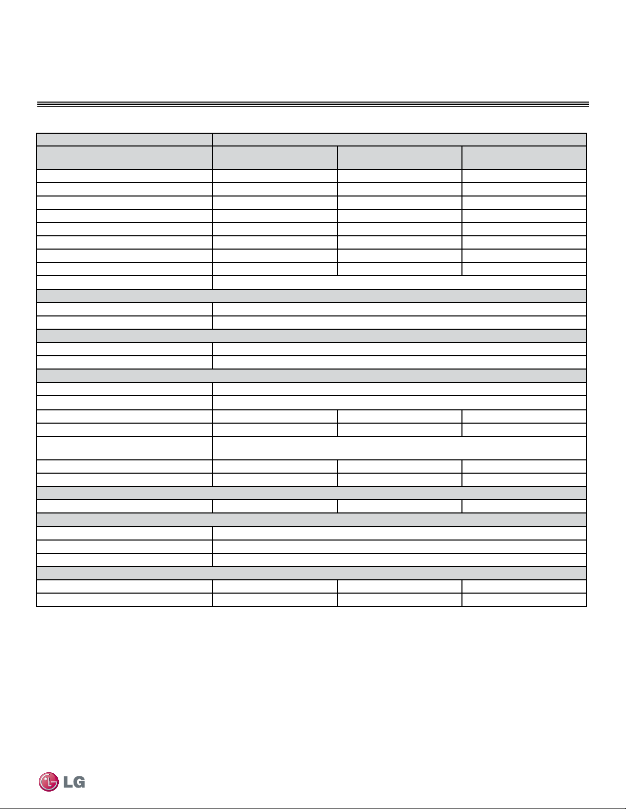
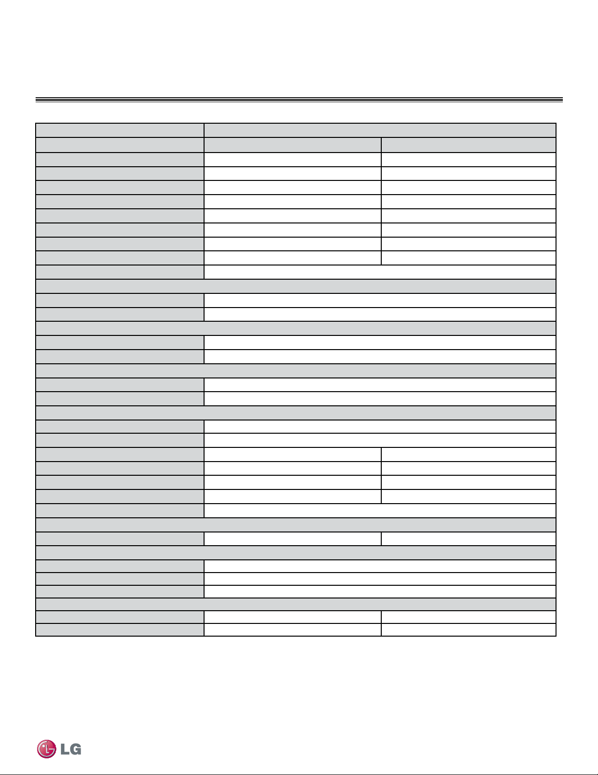
Single Zone Standard Unit Specications
Table 2: Single Zone Standard Unit Specications
Type Single Zone Standard Units
System Model Number (IDU/ODU) LS307HV3 (LSN307HV3/LSU307HV3) LS360HV3 (LSN360HV3/LSU360HV3)
Nominal Cooling Capacity (Btu/h)
30,000 33,000
Cooling Power Input
1
(kW)
3.0 4.0
Nominal Heating Capacity (Btu/h)
1
32,000 35,200
Heating Power Input
1
(kW)
3.1 3.8
COP
3.0 2.7
EER
10.0 8.2
SEER
18.0 16.1
HSPF
9.5 9.9
Power Supply (V/Hz/Ø)
208-230/60/1 208-230/60/1
Outdoor Unit Operating Range
Cooling (°F DB)
14-118 14-118
Heating (°F WB)
-4-75 -4-75
Indoor Unit Operating Range
Cooling (°F)
64-90 64-90
Heating (°F)
60-86 60-86
Unit Data
Refrigerant Type
2
R410A R410A
Refrigerant Control
EEV EEV
IDU Sound Pressure
3
dB(A) (H/M/L)
49/44/39 49/44/39
ODU Sound Pressure
3
dB(A)
55 55
Power/Communication Cable
4
(No. x
AWG)
4 x 18 4 x 18
IDU Net/Shipping Weight (lbs)
36/42 36/42
ODU Net/Shipping Weight (lbs)
128/137 128/137
Compressor
Compressor Type (Qty)
Twin Rotary (1) Twin Rotary (1)
Fan
IDU Type (Qty)
Cross Flow Cross Flow
ODU Type (Qty)
Propeller Propeller
Motor/Drive
Brushless Digitally Controlled/Direct
Airflow Rate
IDU Max/H/M/L (CFM)
883/770/629/424 883/795/629/424
ODU Max (CFM)
2,119 2,119
EEV: Electronic Expansion Valve IDU: Indoor Unit ODU: Outdoor Unit
1
Power Input is rated at high speed.
2
Take appropriate actions at the end of HVAC equipment life to recover, recycle, reclaim or destroy
R410A refrigerant according to applicable regulations (40 CFR Part 82, Subpart F) under section 608
of CAA.
3
Sound Pressure levels are tested in an anechoic chamber under ISO Standard 1996.
4
All power/communication cables to be minimum 18 AWG, 4-conductor, stranded, shielded and must
comply with applicable and national code.
Power wiring is field supplied and must comply with the applicable local and national codes
This unit comes with a dry helium charge.
This data is rated 0 ft above sea level with 24.6 of refrigerant line per indoor unit and a 0 ft level
difference outdoor and indoor units.
Cooling capacity rating obtained with air entering the indoor unit at 80ºF dry bulb (DB) and 67ºF wet
bulb (WB) and outdoor ambient conditions of 95ºF dry bulb (DB) and 75ºF wet bulb (WB).
Heating capacity rating obtained with air entering the indoor unit at 70ºF dry bulb (DB) and 59ºF wet
bulb (WB) and outdoor ambient conditions of 47ºF dry bulb (DB) and 43ºF wet bulb (WB).
12
Single Zone High Efciency, Standard, Extended Pipe and Mega Wall Mount Installation Manual
Due to our policy of continuous product innovation, some specifications may change without notification.
©LG Electronics U.S.A., Inc., Englewood Cliffs, NJ. All rights reserved. “LG” is a registered trademark of LG Corp.
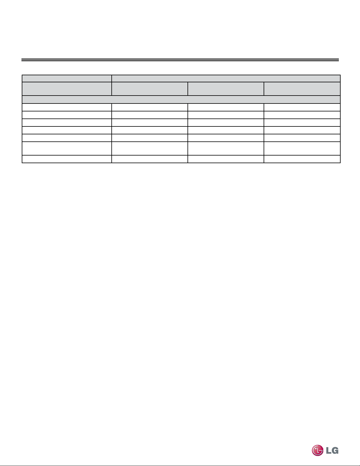
GENERAL DATA
Type Single Zone Standard Units
System Model Number (IDU/ODU) LS307HV3 (LSN307HV3/LSU307HV3) LS360HV3 (LSN360HV3/LSU360HV3)
Piping
Liquid Line (in, OD)
3/8 3/8
Vapor Line (in, OD)
5/8 5/8
Condensation Line (OD/ID)
27/32, 5/8 27/32, 5/8
Additional Refrigerant Charge (oz/ft)
0.38 0.38
Max Pipe Length
5
(ft)
98.4 98.4
Piping Length
5
(no add’l
refrigerant, ft)
24.6 24.6
Max Elevation Difference (ft)
49.2 49.2
Table 2: Single Zone Standard Unit Specications - Continued
EEV: Electronic Expansion Valve IDU: Indoor Unit ODU: Outdoor Unit
5
Piping lengths are equivalent.
Power wiring is field supplied and must comply with the applicable local and national codes
This unit comes with a dry helium charge.
This data is rated 0 ft above sea level with 24.6 of refrigerant line per indoor unit and a 0 ft level
difference outdoor and indoor units.
Cooling capacity rating obtained with air entering the indoor unit at 80ºF dry bulb (DB) and 67ºF wet
bulb (WB) and outdoor ambient conditions of 95ºF dry bulb (DB) and 75ºF wet bulb (WB).
Heating capacity rating obtained with air entering the indoor unit at 70ºF dry bulb (DB) and 59ºF wet
bulb (WB) and outdoor ambient conditions of 47ºF dry bulb (DB) and 43ºF wet bulb (WB).
Single Zone Standard Unit Specications
13
Product Data
Due to our policy of continuous product innovation, some specifications may change without notification.
©LG Electronics U.S.A., Inc., Englewood Cliffs, NJ. All rights reserved. “LG” is a registered trademark of LG Corp.
GENERAL DATA
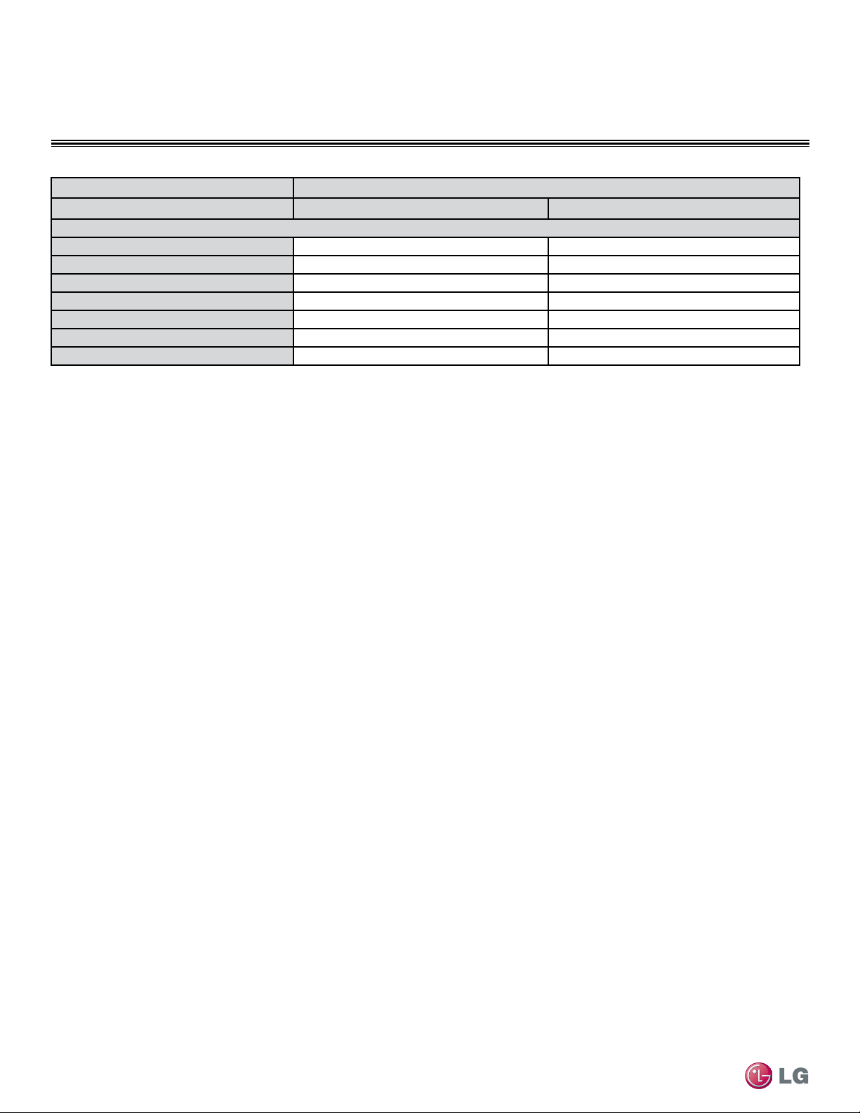
Type Single Zone Extended Pipe Units
System Model Number (IDU/ODU)
LS240HLV (LSN240HLV/
LSU240HLV)
LS300HLV (LSN300HLV/
LSU300HLV)
LS360HLV (LSN360HLV/
LSU360HLV)
Nominal Cooling Capacity (Btu/h)
22,000 30,000 33,000
Cooling Power Input
1
(kW)
1.7 3.0 4.0
Nominal Heating Capacity (Btu/h)
1
27,000 32,000 35,200
Heating Power Input
1
(kW)
2.3 3.1 3.8
COP
3.32 3.03 2.69
EER
12.5 10.0 8.2
SEER
21.0 18.5 16.5
HSPF
11 10 10
Power Supply (V/Hz/Ø)
208-230/60/1
Outdoor Unit Operating Range
Cooling (°F DB)
14-118
Heating (°F WB)
-4-75
Indoor Unit Operating Range
Cooling (°F)
64-90
Heating (°F)
60-86
Unit Data
Refrigerant Type
2
R410A
Refrigerant Control
EEV
IDU Sound Pressure
3
dB(A) (H/M/L)
49/44/40 49/44/40 49/44/40
ODU Sound Pressure
3
dB(A)
55 55 55
Power/Communication Cable
4
(No. x
AWG)
4 x 18
IDU Net/Shipping Weight (lbs)
40/46 40/46 40/46
ODU Net/Shipping Weight (lbs)
125/133 125/133 125/133
Compressor
Compressor Type (Qty)
Twin Rotary (1) Twin Rotary (1) Twin Rotary (1)
Fan
IDU Type (Qty)
Cross Flow
ODU Type (Qty)
Propeller
Motor/Drive
Brushless Digitally Controlled/Direct
Airflow Rate
IDU Max/H/M/L (CFM)
848/706/530/459 848/706/530/459 848/706/530/459
ODU Max (CFM)
2,119 2,119 2,119
Table 3: Single Zone Extended Pipe Unit Specications
EEV: Electronic Expansion Valve IDU: Indoor Unit ODU: Outdoor Unit
1
Power Input is rated at high speed.
2
Take appropriate actions at the end of HVAC equipment life to recover, recycle, reclaim or destroy
R410A refrigerant according to applicable regulations (40 CFR Part 82, Subpart F) under section 608
of CAA.
3
Sound Pressure levels are tested in an anechoic chamber under ISO Standard 1996.
4
All power/communication cables to be minimum 18 AWG, 4-conductor, stranded, shielded and must
comply with applicable and national code.
Power wiring is field supplied and must comply with the applicable local and national codes
This unit comes with a dry helium charge.
This data is rated 0 ft above sea level with 24.6 of refrigerant line per indoor unit and a 0 ft level
difference outdoor and indoor units.
Cooling capacity rating obtained with air entering the indoor unit at 80ºF dry bulb (DB) and 67ºF wet
bulb (WB) and outdoor ambient conditions of 95ºF dry bulb (DB) and 75ºF wet bulb (WB).
Heating capacity rating obtained with air entering the indoor unit at 70ºF dry bulb (DB) and 59ºF wet
bulb (WB) and outdoor ambient conditions of 47ºF dry bulb (DB) and 43ºF wet bulb (WB).
Single Zone Extended Pipe Unit Specications
14
Single Zone High Efciency, Standard, Extended Pipe and Mega Wall Mount Installation Manual
Due to our policy of continuous product innovation, some specifications may change without notification.
©LG Electronics U.S.A., Inc., Englewood Cliffs, NJ. All rights reserved. “LG” is a registered trademark of LG Corp.
GENERAL DATA
Type Single Zone Extended Pipe Units
System Model Number (IDU/ODU)
LS240HLV (LSN240HLV/
LSU240HLV)
LS300HLV (LSN300HLV/
LSU300HLV)
LS360HLV (LSN360HLV/
LSU360HLV)
Piping
Liquid Line (in, OD)
3/8 3/8 3/8
Vapor Line (in, OD)
5/8 5/8 5/8
Condensation Line (OD, ID)
27/32, 5/8 27/32, 5/8 27/32, 5/8
Additional Refrigerant Charge (oz/ft)
0.38 0.38 0.38
Max Pipe Length
5
(ft)
164 164 164
Piping Length
5
(no add’l
refrigerant, ft)
24.6 24.6 24.6
Max Elevation Difference (ft)
98.4 98.4 98.4
Table 3: Single Zone Extended Pipe Unit Specications - Continued
EEV: Electronic Expansion Valve IDU: Indoor Unit ODU: Outdoor Unit
5
Piping lengths are equivalent.
Power wiring is field supplied and must comply with the applicable local and national codes
This unit comes with a dry helium charge.
This data is rated 0 ft above sea level with 24.6 of refrigerant line per indoor unit and a 0 ft level
difference outdoor and indoor units.
Cooling capacity rating obtained with air entering the indoor unit at 80ºF dry bulb (DB) and 67ºF wet
bulb (WB) and outdoor ambient conditions of 95ºF dry bulb (DB) and 75ºF wet bulb (WB).
Heating capacity rating obtained with air entering the indoor unit at 70ºF dry bulb (DB) and 59ºF wet
bulb (WB) and outdoor ambient conditions of 47ºF dry bulb (DB) and 43ºF wet bulb (WB).
Single Zone Extended Pipe Unit Specications
15
Product Data
Due to our policy of continuous product innovation, some specifications may change without notification.
©LG Electronics U.S.A., Inc., Englewood Cliffs, NJ. All rights reserved. “LG” is a registered trademark of LG Corp.
GENERAL DATA
Single Zone Mega Unit Specications
Type Single Zone Mega Inverter
System (Model IDU/ODU) LS090HEV (LSN090HEV/LSU090HEV) LS120HEV (LSN120HEV/LSU120HEV)
Nominal Cooling Capacity (Btu/h) 8,500 12,000
Cooling Power Input
1
(kW) 0.78 1.17
Nominal Heating Capacity (Btu/h) 9,000 12,000
Heating Power Input
1
(kW) 0.78 0.98
COP 3.19 3.00
EER 10.90 10.26
SEER 16.3 16.3
HSPF 8.3 8.5
Power Supply (V / Hz / Ø) 208-230/60/1
ODU Operating Range
Cooling (°F DB) 64-118
Heating (°F WB) 23-75
IDU Operating Range
Cooling (°F WB) 64-90
Heating (°F DB) 60-86
Indoor Temperature Setting Range
Cooling (°F) 65-86
Heating (°F) 61-86
Unit Data
Refrigerant Type
2
R410A
Refrigerant Control Capillary Tube
IDU Sound Pressure
3
± 3 dB(A) (H/M/L) 39/33/25 39/33/25
ODU Sound Pressure ± 3 dB(A) 47 47
Indoor Unit (Net/Shipping Weight lbs.) 16/21 20/25
Outdoor Unit (Net/Shipping Weight lbs.) 52/56 49/53
Power/Communication Cable
4
(No. x AWG) 4 x 18
Compressor
Compressor Type (Qty)
Single Rotary (1) Single Rotary (1)
Fan
Indoor Type (Qty) Cross Flow (1)
Outdoor Type (Qty) Propeller (1)
Motor/Drive Brushless Digitally Controlled/Direct
Airflow Rate
Indoor - Max/H/M/L (CFM) 318/276/226/177
424/353/272/212
Outdoor - Max (CFM) 953 953
Table 4: Single Zone Mega Unit Specications
16
Single Zone High Efciency, Standard, Extended Pipe and Mega Wall Mount Installation Manual
Due to our policy of continuous product innovation, some specifications may change without notification.
©LG Electronics U.S.A., Inc., Englewood Cliffs, NJ. All rights reserved. “LG” is a registered trademark of LG Corp.
GENERAL DATA
EEV: Electronic Expansion Valve
Power wiring is field supplied and must comply with the applicable local and national codes.
This unit comes with a dry helium charge.
This data is rated 0 ft above sea level, with 24.6 ft of refrigerant line per indoor unit and a 0 ft level difference
between outdoor and indoor units. All capacities are net with a combination ratio between 95-105%.
Cooling capacity rating obtained with air entering the indoor coil at 80ºF dry bulb (DB) and 67ºF wet bulb (WB);
and outdoor ambient conditions of 95ºF dry bulb (DB) and 75ºF wet bulb (WB).
Heating capacity rating obtained with air entering the indoor unit at 70ºF dry bulb (DB) and 60ºF wet bulb (WB);
and outdoor ambient conditions of 47ºF dry bulb (DB) and 43ºF wet bulb (WB).
1
Power Input is rated at high speed.
2
Take appropriate actions at the end of HVAC equipment life to recover, recycle, reclaim or
destroy R410A refrigerant according to applicable regulations (40 CFR Part 82, Subpart F)
under section 608 of CAA.
3
Sound Pressure levels are tested in an anechoic chamber under ISO Standard 1996.
4
All power/communication cable to be minimum 18 AWG, 4-conductor, stranded, shielded
and must comply with applicable and national code.
5
Piping lengths are equivalent.
Type Single Zone Mega Inverter
System (Model IDU/ODU) LS090HEV (LSN090HEV/LSU090HEV) LS120HEV (LSN120HEV/LSU120HEV)
Piping
Liquid Line (in, OD) 1/4 1/4
Vapor Line (in, OD) 3/8 3/8
Condensation Line (OD | ID) 27/32 | 5/8 27/32 | 5/8
Additional Refrigerant Charge (oz/ft) 0.22 0.22
Max Pipe Length (ft)
5
49.2 49.2
Piping Length (no add’l refrigerant, ft)
5
24.6 24.6
Max Elevation Difference (ft) 22.9 22.9
Table 4: Single Zone Mega Unit Specications - Continued
Single Zone Mega Unit Specications

17
Product Data
Due to our policy of continuous product innovation, some specifications may change without notification.
©LG Electronics U.S.A., Inc., Englewood Cliffs, NJ. All rights reserved. “LG” is a registered trademark of LG Corp.
GENERAL DATA
Table 4: Single Zone Mega Unit Specications - Continued
Single Zone Mega Unit Specications
Type Single Zone Mega Inverter
System (Model IDU/ODU) LS180HEV (LSN180HEV/LSU180HEV) LS240HEV (LSN240HEV/LSU240HEV)
Nominal Cooling Capacity (Btu/h) 17,000 22,000
Cooling Power Input
1
(kW) 1.55 2.04
Nominal Heating Capacity (Btu/h) 19,000 22,000
Heating Power Input
1
(kW) 1.59 1.93
COP 3.19 3.00
EER 10.95 10.75
SEER 17.0 17.0
HSPF 8.7 8.5
Power Supply (V / Hz / Ø) 208-230/60/1
ODU Operating Range
Cooling (°F DB) 64-118
Heating (°F WB) 23-75
IDU Operating Range
Cooling (°F WB) 64-90
Heating (°F DB) 60-86
Indoor Temperature Setting Range
Cooling (°F) 65-86
Heating (°F) 61-86
Unit Data
Refrigerant Type
2
R410A
Refrigerant Control Capillary Tube
IDU Sound Pressure
3
± 3 dB(A) (H/M/L) 42/40/35 45/40/35
ODU Sound Pressure ± 3 dB(A) 51 53
Indoor Unit (Net/Shipping Weight lbs.) 28/30 28/34
Outdoor Unit (Net/Shipping Weight lbs.) 72/77 92/104
Power/Communication Cable
4
(No. x AWG) 4 x 18
Compressor
Compressor Type (Qty)
Twin Rotary (1) Twin Rotary (1)
Fan
Indoor Type (Qty) Cross Flow (1)
Outdoor Type (Qty) Propeller (1)
Motor/Drive Brushless Digitally Controlled/Direct
Airflow Rate
Indoor - Max/H/M/L (CFM) 629/512/441/353
689/600/494/388
Outdoor - Max (CFM) 1,342 1,766

18
Single Zone High Efciency, Standard, Extended Pipe and Mega Wall Mount Installation Manual
Due to our policy of continuous product innovation, some specifications may change without notification.
©LG Electronics U.S.A., Inc., Englewood Cliffs, NJ. All rights reserved. “LG” is a registered trademark of LG Corp.
GENERAL DATA
Type Single Zone Mega Inverter
System (Model IDU/ODU) LS180HEV (LSN180HEV/LSU180HEV) LS240HEV (LSN240HEV/LSU240HEV)
Piping
Liquid Line (in, OD) 1/4 1/4
Vapor Line (in, OD) 1/2 5/8
Condensation Line (OD | ID) 27/32 | 5/8 27/32 | 5/8
Additional Refrigerant Charge (oz/ft) 0.33 0.33
Max Pipe Length (ft)
5
65.6 65.6
Piping Length (no add’l refrigerant, ft)
5
24.6 24.6
Max Elevation Difference (ft) 32.8 32.8
EEV: Electronic Expansion Valve
Power wiring is field supplied and must comply with the applicable local and national codes.
This unit comes with a dry helium charge.
This data is rated 0 ft above sea level, with 24.6 ft of refrigerant line per indoor unit and a 0 ft level difference
between outdoor and indoor units. All capacities are net with a combination ratio between 95-105%.
Cooling capacity rating obtained with air entering the indoor coil at 80ºF dry bulb (DB) and 67ºF wet bulb (WB);
and outdoor ambient conditions of 95ºF dry bulb (DB) and 75ºF wet bulb (WB).
Heating capacity rating obtained with air entering the indoor unit at 70ºF dry bulb (DB) and 60ºF wet bulb (WB);
and outdoor ambient conditions of 47ºF dry bulb (DB) and 43ºF wet bulb (WB).
1
Power Input is rated at high speed.
2
Take appropriate actions at the end of HVAC equipment life to recover, recycle, reclaim or
destroy R410A refrigerant according to applicable regulations (40 CFR Part 82, Subpart F)
under section 608 of CAA.
3
Sound Pressure levels are tested in an anechoic chamber under ISO Standard 1996.
4
All power/communication cable to be minimum 18 AWG, 4-conductor, stranded, shielded
and must comply with applicable and national code.
5
Piping lengths are equivalent.
Table 4: Single Zone Mega Unit Specications - Continued
Single Zone Mega Unit Specications
19
Product Data
Due to our policy of continuous product innovation, some specifications may change without notification.
©LG Electronics U.S.A., Inc., Englewood Cliffs, NJ. All rights reserved. “LG” is a registered trademark of LG Corp.
GENERAL DATA
Single Zone Mega115V Unit Specications
Type Single Zone Mega Inverter
System (Model IDU/ODU) LS090HXV (LSN090HXV/LSU090HXV) LS120HXV (LSN120HXV/LSU120HXV)
Nominal Cooling Capacity (Btu/h) 8,500 12,000
Cooling Power Input
1
(kW) 0.71 1.14
Nominal Heating Capacity (Btu/h) 10,900 13,000
Heating Power Input
1
(kW) 0.88 1.09
COP 3.63 3.50
EER 12.01 10.5
SEER 17.0 17.0
HSPF 9.0 9.0
Power Supply (V / Hz / Ø) 115/60/1
ODU Operating Range
Cooling (°F DB) 14-118
Heating (°F WB) 14-75
IDU Operating Range
Cooling (°F WB) 64-90
Heating (°F DB) 60-86
Indoor Temperature Setting Range
Cooling (°F) 65-86
Heating (°F) 61-86
Unit Data
Refrigerant Type
2
R410A
Refrigerant Control EEV
IDU Sound Pressure
3
± 3 dB(A) (H/M/L) 39/33/25 39/33/25
ODU Sound Pressure ± 3 dB(A) 47 47
Indoor Unit (Net/Shipping Weight lbs.) 23/26 23/26
Outdoor Unit (Net/Shipping Weight lbs.) 67/79 67/79
Power/Communication Cable
4
(No. x AWG) 4 x 18
Compressor
Compressor Type (Qty)
Single Rotary (1) Single Rotary (1)
Fan
Indoor Type (Qty) Cross Flow (1)
Outdoor Type (Qty) Propeller (1)
Motor/Drive Brushless Digitally Controlled/Direct
Airflow Rate
Indoor - Max/H/M/L (CFM) 335/272/212/124 335/272/212/124
Outdoor - Max (CFM) 1,000 1,000
Table 5: Single Zone Mega 115V Unit Specications
20
Single Zone High Efciency, Standard, Extended Pipe and Mega Wall Mount Installation Manual
Due to our policy of continuous product innovation, some specifications may change without notification.
©LG Electronics U.S.A., Inc., Englewood Cliffs, NJ. All rights reserved. “LG” is a registered trademark of LG Corp.
GENERAL DATA
EEV: Electronic Expansion Valve
Power wiring is field supplied and must comply with the applicable local and national codes.
This unit comes with a dry helium charge.
This data is rated 0 ft above sea level, with 24.6 ft of refrigerant line per indoor unit and a 0 ft level difference
between outdoor and indoor units. All capacities are net with a combination ratio between 95-105%.
Cooling capacity rating obtained with air entering the indoor coil at 80ºF dry bulb (DB) and 67ºF wet bulb (WB);
and outdoor ambient conditions of 95ºF dry bulb (DB) and 75ºF wet bulb (WB).
Heating capacity rating obtained with air entering the indoor unit at 70ºF dry bulb (DB) and 60ºF wet bulb (WB);
and outdoor ambient conditions of 47ºF dry bulb (DB) and 43ºF wet bulb (WB).
1
Power Input is rated at high speed.
2
Take appropriate actions at the end of HVAC equipment life to recover, recycle, reclaim or
destroy R410A refrigerant according to applicable regulations (40 CFR Part 82, Subpart F)
under section 608 of CAA.
3
Sound Pressure levels are tested in an anechoic chamber under ISO Standard 1996.
4
All power/communication cable to be minimum 18 AWG, 4-conductor, stranded, shielded
and must comply with applicable and national code.
5
Piping lengths are equivalent.
Type Single Zone Mega Inverter
System (Model IDU/ODU) LS090HXV (LSN090HXV/LSU090HXV) LS120HXV (LSN120HXV/LSU120HXV)
Piping
Liquid Line (in, OD) 1/4 1/4
Vapor Line (in, OD) 3/8 3/8
Condensation Line (OD | ID) 27/32 | 5/8 27/32 | 5/8
Additional Refrigerant Charge (oz/ft) 0.22 0.22
Max Pipe Length (ft)
5
49.2 49.2
Piping Length (no add’l refrigerant, ft)
5
24.6 24.6
Max Elevation Difference (ft) 23 23
Table 5: Single Zone Mega 115V Unit Specications - Continued
21
Product Data
Due to our policy of continuous product innovation, some specifications may change without notification.
©LG Electronics U.S.A., Inc., Englewood Cliffs, NJ. All rights reserved. “LG” is a registered trademark of LG Corp.
GENERAL DATA
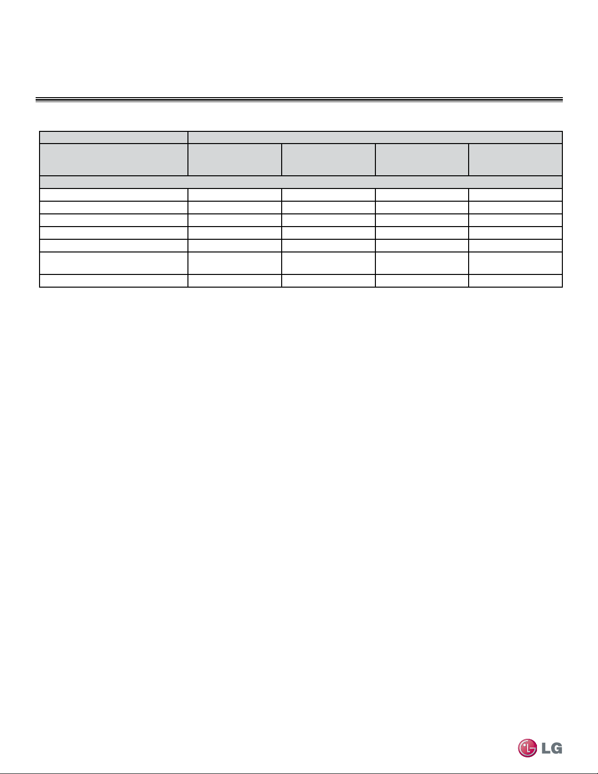
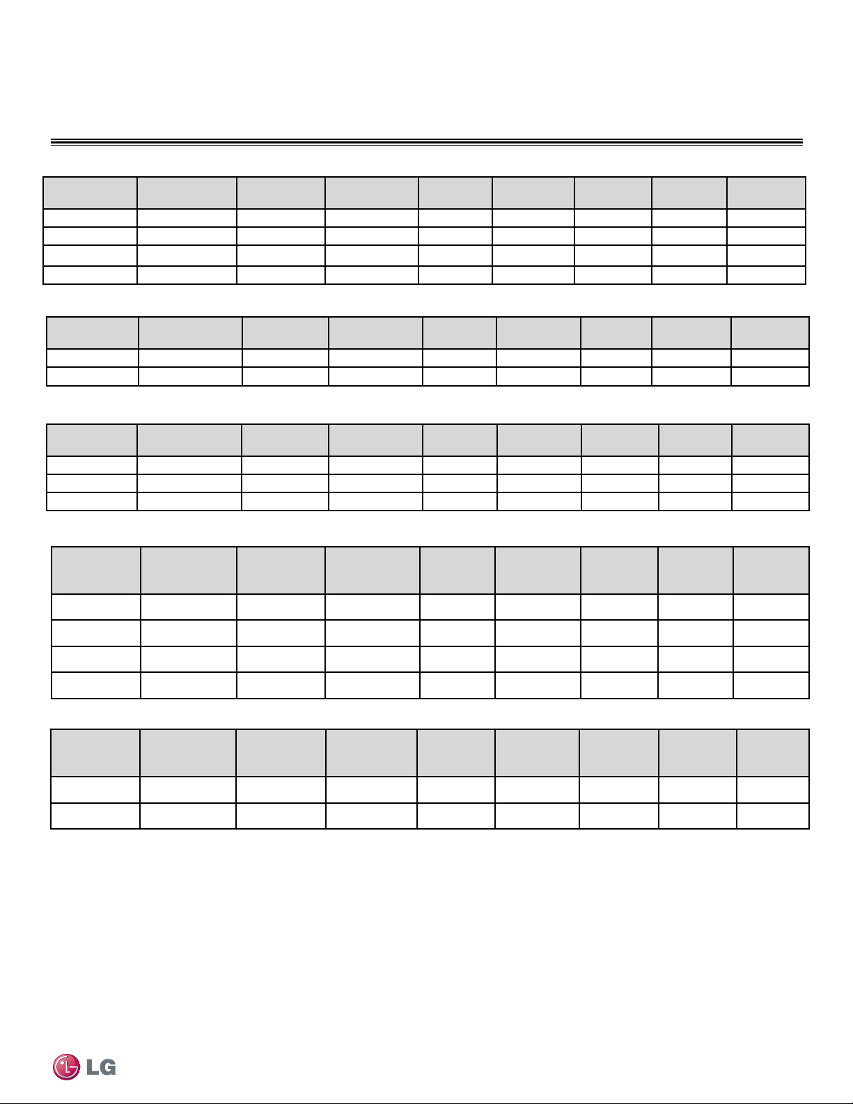
Model Number Nom. Tons
Compressor
Qty
Compressor
(A) Cool/Heat
Fan Qty ODU Fan (A) IDU Fan (A) MCA (A) MOP (A)
LSU091HSV3
3/4 1 8.7/8.7 1 0.40 0.4 10 15
LSU121HSV3
1 1 8.7/8.7 1 0.40 0.4 10 15
LSU181HSV3
1-1/2 1 15.4/15.4 1 0.25 0.4 19 25
LSU240HSV3
1-3/4 1 15.4/15.4 1 0.25 0.5 19 25
Table 6: Single Zone High Efciency Indoor Unit Electrical Data
Model Number Nom. Tons
Compressor
Qty
Compressor
(A) Cool/Heat
Fan Qty ODU Fan (A) IDU Fan (A) MCA (A) MOP (A)
LSU307HV3
2-1/2 1 15.4/15.4 1 0.25 0.5 19 25
LSU360HV3
2-3/4 1 15.4/15.4 1 0.25 0.5 19 25
Table 7: Single Zone Standard Indoor Unit Electrical Data
Model Number Nom. Tons
Compressor
Qty
Compressor
(A) Cool/Heat
Fan Qty ODU Fan (A) IDU Fan (A) MCA (A) MOP (A)
LSU240HLV
1-3/4 1 17.3/17.3 1 0.25 0.5 23 35
LSU300HLV
2-1/2 1 17.3/17.3 1 0.25 0.5 23 35
LSU360HLV
2-3/4 1 17.3/17.3 1 0.25 0.5 23 35
Table 8: Single Zone Extended Pipe Indoor Unit Electrical Data
Electrical
Unit Model Nos. Nom. Tons
Compressor
Qty
Compressor
(A) Cool/Heat
Fan Qty ODU Fan (A) IDU Fan (A) MCA (A) MOP (A)
LSU090HEV
3/4 1 6.8/6.8 1 0.5 0.5 9 15
LSU120HEV
1 1 6.8/6.8 1 0.5 0.5 9 15
LSU180HEV
1 1/2 1 8.68/9.28 1 0.4 0.4 12 20
LSU240HEV
2 1 10.8/9.6 1 0.48 0.48 14 20
Table 9: 208-230V, 60Hz, 1-Phase Single Zone Mega Indoor Unit Electrical Data
Table 10: 115V, 60Hz, 1-Phase Single Zone Mega 115V Indoor Unit Electrical Data
Unit Model Nos. Nom. Tons
Compressor
Qty
Compressor
(A) Cool/Heat
Fan Qty ODU Fan (A) IDU Fan (A) MCA (A) MOP (A)
LSU090HXV
3/4 1 10/10 1 0.4 0.5 13.5 20
LSU120HXV
1 1 10/10 1 0.4 0.5 13.5 20
Voltage tolerance is ±10%.
Maximum allowable voltage unbalance is 2%.
MSC = Maximum Starting Current.
MCA = Minimum Circuit Ampacity.
Maximum Overcurrent Protection (MOP) is calculated
as follows: (Largest motor FLA x 2.25) + (Sum of
other motor FLA) rounded down to the nearest
standard fuse size.
22
Single Zone High Efciency, Standard, Extended Pipe and Mega Wall Mount Installation Manual
Due to our policy of continuous product innovation, some specifications may change without notification.
©LG Electronics U.S.A., Inc., Englewood Cliffs, NJ. All rights reserved. “LG” is a registered trademark of LG Corp.
GENERAL DATA
R410A Refrigerant
• Piping wall thickness must comply with the applicable local, state, and federal codes for the 551 psi design pressure of R410A.
• Because R410A is a combination of R32 and R125, the required additional refrigerant must be charged in its liquid state. If the refrig-
erant is charged in its gaseous state, its composition changes and the system will not work properly.
R410A Refrigerant
R410A refrigerant has a higher operating pressure in comparison to R22 refrigerant and, therefore, all piping system materials installed must
have a higher resisting pressure than the materials traditionally used in R22 systems.
R410A refrigerant is an azeotrope of R32 and R125, mixed at 50:50, so the ozone depletion potential (ODP) is 0. Many countries have
approved of and encouraged R410A for use as an environment friendly refrigerant.
• To prevent the refrigerant cylinder from exploding, do not place it in direct sunlight.
• Do not use any piping that has not been approved for use in high-pressure refrigerant systems.
• To prevent the piping from softening, do not heat it more than necessary during installation.
23
General Installation Guidelines
Due to our policy of continuous product innovation, some specifications may change without notification.
©LG Electronics U.S.A., Inc., Englewood Cliffs, NJ. All rights reserved. “LG” is a registered trademark of LG Corp.
GENERAL INSTALLATION GUIDELINES
Location Selection
Selecting the Best Location
DANGER
• To avoid the possibility of fire, do not install the unit in an area where combustible gas may generate, flow, stagnate, or leak.
• Do not install the unit in a location where acidic solution and spray (sulfur) are often used.
• Do not use the unit in environments where oil, steam, or sulfuric gas are present.
Install a fence to prevent vermin from crawling into the unit or unauthorized individuals from accessing it.
Select a location for installing the outdoor unit that will meet the following conditions:
• Where the unit will not be subjected to direct thermal radiation from other heat sources.
• Where operating sound from the unit will not disturb inhabitants of surrounding buildings.
• Where the unit will not be exposed to direct, strong winds.
• Where there is enough strength to bear the weight of the unit.
• Include space for drainage to ensure condensate flows properly out of the unit when it is in heating mode.
• Include enough space for air flow and for service access.
To ensure the outdoor unit operates properly, certain measures are required in locations where there is a possibility of heavy snowfall or
severe windchill or cold:
1. Prepare for severe winter wind chills and heavy snowfall, even in areas of the country where these are unusual phenomena.
2. Position the outdoor unit so that its airflow fans are not buried by direct, heavy snowfall. If snow piles up and blocks the airflow, the
system may malfunction.
3. Remove any snow that has accumulated 3-15/16 inches or more on the top of the outdoor unit.
4. Place the outdoor unit on a raised platform at least 19-11/16 inches higher than the average annual snowfall for the area. In environments
where there is a possibility of heavy snow, the frame height must be more than two (2) times the amount of average annual snowfall, and
should not exceed the width of the outdoor unit. If the frame width is wider than the outdoor unit, snow may accumulate.
5. Install a snow protection hood.
6. To prevent snow and heavy rain from entering the outdoor unit, install the suction and discharge ducts facing away from direct winds.
7. Additionally, the following conditions should be taken into considerations when the unit operates in defrost mode:
• If the outdoor unit is installed in a highly humid environment (near an ocean, lake, etc.), ensure that the site is well-ventilated and has a lot
of natural light. (Example: Install on a rooftop.)
• Sidewalks or parking lots near the outdoor unit may accumulate moisture after unit operates in defrost mode that can turn to ice.
The indoor unit may take longer to provide heat, or heating performance will be reduced in winter if the unit is installed:
1. In a narrow, shady location.
2. Near a location that has a lot of ground moisture.
3. In a highly humid environment.
4. In an area in which condensate does not drain properly.
Ambient Air Conditions
• Avoid exposing the outdoor unit to steam, combustible gases, or other corrosive elements.
• Avoid exposing the unit to discharge from boiler stacks, chimneys, steam relief ports, other air conditioning units, kitchen vents, plumbing
vents, or substances that may degrade performance or cause damage to the unit.
• When installing multiple outdoor units, avoid placing the units where discharge of one outdoor unit will blow into the inlet side of an adja-
cent unit.
Avoid exposing the unit to sources of extreme temperature or gases to prevent serious bodily injury.
24
Single Zone High Efciency, Standard, Extended Pipe and Mega Wall Mount Installation Manual
Due to our policy of continuous product innovation, some specifications may change without notification.
©LG Electronics U.S.A., Inc., Englewood Cliffs, NJ. All rights reserved. “LG” is a registered trademark of LG Corp.
GENERAL INSTALLATION GUIDELINES
• The unit should be installed in a soundproofed mechanical room.
• Avoid installing the outdoor unit where it would be directly exposed
to ocean winds.
• Install the outdoor unit on the side of the building opposite from
direct ocean winds.
• Select a location with good drainage.
• Periodically clean dust or salt particles off of the heat exchanger
with water.
• If the outdoor unit must be placed in a location where it would
be subjected to direct ocean winds, install a concrete windbreak
strong enough to block any winds.
• Windbreak should be more than 150% of the outdoor unit’s height.
There must be 2ft and 3 1/2 inches clearance between the outdoor
unit and the windbreaker for purposes of air flow.
Additional anti-corrosion treatment may need to be applied to the
outdoor unit at oceanside locations.
Ocean winds may cause corrosion, particularly on the condenser and
evaporator ns, which, in turn could cause product malfunction or
inefcient performance.
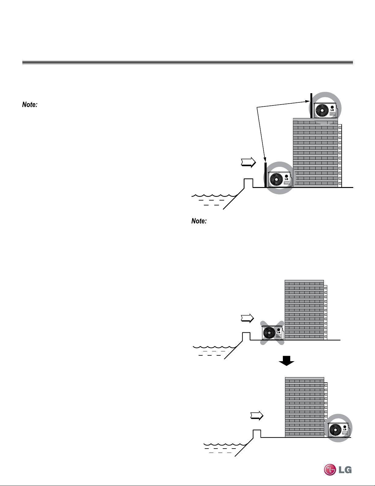
Oceanside Applications
Figure 1: Oceanside Placement Using Windbreak
Figure 2: Placement Using Building as Shield
Oceanside Applications
Use of a Windbreak to Shield from Sea Wind
Sea wind
Windbreak
Oceanside Applications
Use of a Building to Shield from Sea Wind
Sea wind
Sea wind
Building
Building
If a windbreak is not possible, a building or larger structure must
be used to shield the outdoor unit from direct exposure to the sea
wind. The unit should be placed on the side of the building directly
opposite to the direction of the wind as shown in Figure 2.
25
General Installation Guidelines
Due to our policy of continuous product innovation, some specifications may change without notification.
©LG Electronics U.S.A., Inc., Englewood Cliffs, NJ. All rights reserved. “LG” is a registered trademark of LG Corp.
GENERAL INSTALLATION GUIDELINES
Mounting Bolt Location
General Mounting
Securely attach the outdoor unit to a condenser pad, base rails, or
another mounting platform that is securely anchored to the ground
or building structure. Attach the outdoor unit with a bolt and nut on a
concrete or rigid mount. See Figure 3. Follow applicable local codes
for clearance, mounting, anchor and vibration attenuation require-
ments.
All referenced materials are to be eld-supplied. Images are not to scale.
Figure 3: Outdoor Unit Mounting Methods
Bolt
Placement
& Anti-Vibration
Pad
Piping Connection
Top of Unit
Foundation
Mounting Platform
The underlying structure or foundation must be designed to support
the weight of the unit. Avoid placing the unit in a low lying area
where water may accumulate. When installing the outdoor unit on
the wall, or roof top, anchor the mounting base securely to account
for wind, earthquake or vibration.
Tie-Downs and Wind Restraints
The strength of the Duct-free Split Single Zone Inverter system
frame is adequate to be used with field-provided wind restraint tie-
downs. The overall tie-down configuration must be approved by a
local professional engineer. Always refer to local code when design-
ing a wind restraint system.
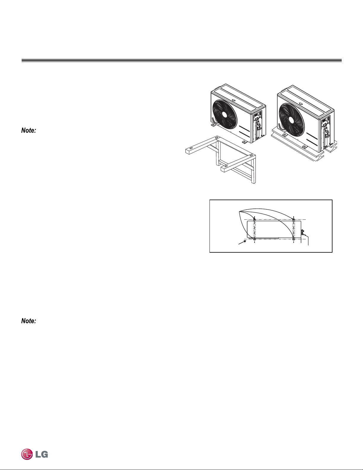
Snow and Ice Conditions
In climates that experience snow build-up, place the unit on a raised platform to ensure condenser airflow. The raised support platform must
be high enough to allow the unit to remain above possible snow drifts. Mount the unit on a field-provided snow stand at a minimum height
that is equal to the average annual snowfall plus 20 inches. Design the mounting base to prevent snow accumulation on the platform in front
or back of the unit case. If necessary, provide a field fabricated hood to keep snow and ice and/or drifting snow from accumulating on the coil
surfaces. Use inlet and discharge duct or hoods to prevent snow or rain from accumulating on the fan inlet and outlet guards. Best practice
prevents snow from accumulating on top of the unit. Consider tie-down requirements in case of high winds or where required by local codes.
When deciding on a location to place the outdoor unit, be sure to choose an area where run-off from defrost will not accumulate and freeze on
sidewalks or driveways.
26
Single Zone High Efciency, Standard, Extended Pipe and Mega Wall Mount Installation Manual
Due to our policy of continuous product innovation, some specifications may change without notification.
©LG Electronics U.S.A., Inc., Englewood Cliffs, NJ. All rights reserved. “LG” is a registered trademark of LG Corp.
GENERAL INSTALLATION GUIDELINES
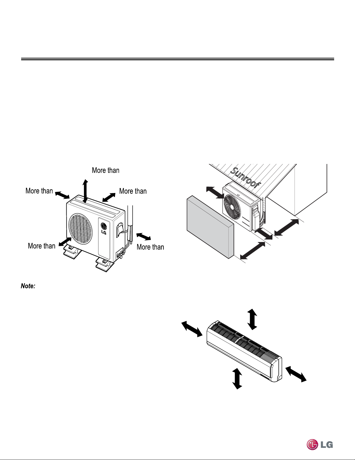
Proper airflow through the Single Zone outdoor unit coil is critical for correct unit operation. When installing, consider service, inlet and outlet,
and minimum allowable space requirements as illustrated in the diagrams below.
Required Clearances
Minimum Clearance Requirements for Single Zone
Specific clearance requirements in the diagram below are for the single zone wall mount systems. Figure 4 shows the overall minimum
clearances that must be observed for safe operation and adequate airflow around the outdoor unit.
When placing the outdoor unit under an overhang, awning, sunroof or other “roof-like structure, observe the clearance requirements (as shown in
Figure 5) for height in relation to the unit. This clearance ensures that heat radiation from the condenser is not restricted around the unit.
Adhere to all clearance requirements if installing the unit on a roof. Be sure to level the unit and ensure that the unit is adequately anchored.
Consult local codes for rooftop mounting requirements.
Figure 4: Outdoor Unit Clearances
Outdoor Unit Clearance
12
28
24
12
24
Unit : inch
Do not place the unit where animals and/or plants will be in the path of the warm air, or where the warm air and/or noise will disturb neighbors.
Figure 5: Outdoor Unit Sunroof/Awning Clearances
More than
12
More than
12
Sunroof
Fence or
obstacles
More than
28
Unit : inch
More than
24
More than 8
More than 4
More than 4
At least 6.5 from the floor
Unit: Inch
Outdoor Unit Clearance
Indoor Unit Clearance
Follow recommended best practices when choosing an indoor loca-
tion for the Single Zone indoor unit.
• Keep unit away from any indoor steam or excessive heat.
• No obstacles should be placed around unit.
• Condensation drain (Leakage piping) should be routed away from
the unit.
• Do not install near doorway.
• Clearance gap between any wall or enclosure and the left or right
side of the unit must be greater than 4 inches.
• From the top of the unit to the ceiling there must greater than 8
inches of clearance.
• Unit should be at least 6.5 feet from the oor for adequate clearance.
27
General Installation Guidelines
Due to our policy of continuous product innovation, some specifications may change without notification.
©LG Electronics U.S.A., Inc., Englewood Cliffs, NJ. All rights reserved. “LG” is a registered trademark of LG Corp.
GENERAL INSTALLATION GUIDELINES
Mounting of Indoor Unit Installation Plate
Follow the procedure and best practices below when mounting the
indoor unit’s plate to a wall.
Procedure
1. Before installation of the plate, confirm the position the screw
types (A or B) between chassis and installation plate.
2. Mount the installation plate horizontally by aligning the centerline
using a leveling tool (Figure 8).
3. Use provided screws when mounting the plating.
• If mounting the unit on concrete wall, use field supplied anchor
bolts.
4. Observe the left and right rear piping clearance when drilling into
the wall, as shown in Figure 8 (181HSV3, 180HEV, 240HEV) and
Figure 9 (091HSV3, 121HSV3).
Select location carefully. Unit should be anchored to a strong wall to pre-
vent unnecessary vibration.
• When choosing a location for the wall mount plate, be sure to take
into consideration routing of wiring for power outlets within the wall.
Contacting wiring can cause serious bodily injury, or death.
• Use caution when drilling holes through the walls for the purposes
of piping connections. Power wiring can cause serious bodily injury,
or death.
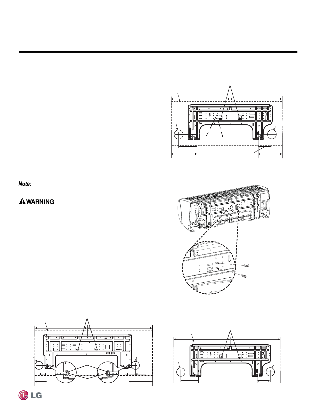
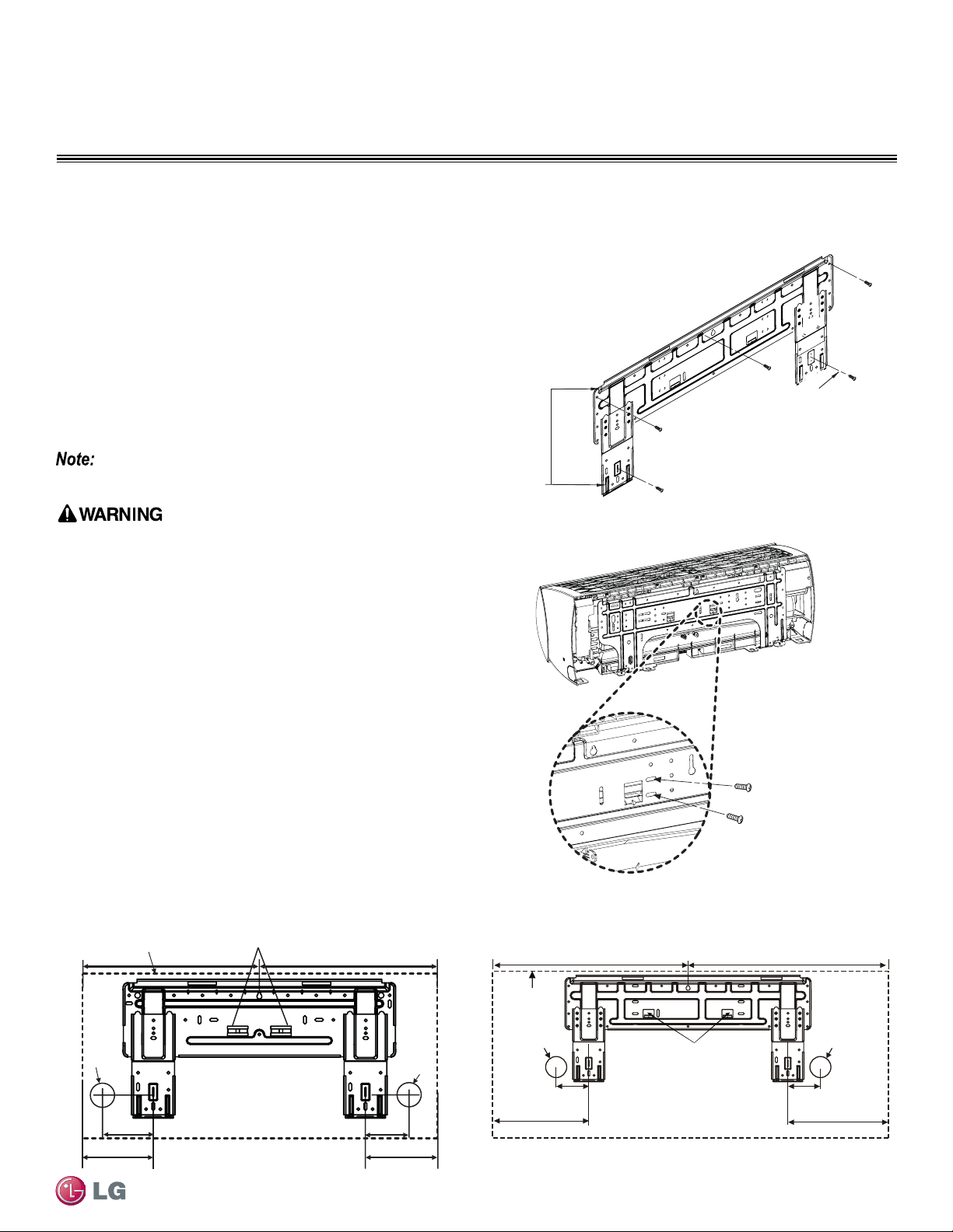
Mounting Installation Plate to Wall (091HSV3, 121HSV3, 181HSV3)
Ø2-19/32
4-
27/32
3- 24/32
Left
rear piping
Installation Plate
Place a level on raised tab
Unit Outline
8-
17/32
6-
29/32
17-13/32 17-13/32
Unit: Inch
091HSV3, 121HSV3
Right
rear piping
Ø2-19/32
Figure 6: Installation Plate Screws - 091HSV3, 121HSV3
Unit: Inch
Ø2-19/32
Ø2-19/32
2 -11/16
2-3/16
Right rear
piping
Left rear
piping
Installation Plate
Measuring Tape
Measuring Tape
Hanger
Place a level on raised tab
Unit Outline
8-3/32
4-3/32
18-3/32 22-13/32
181HSV3
180HEV
240HEV
Ø65
123
A Type : 95
B Type : 170
A Type B Type
Right rear piping
Left rear piping
Place a level on raised tab
Unit
Outline
217
175
(Unit : mm)
A Type : 442
B Type : 434
A Type : 442
B Type : 439
Ø65Ø65
Installation Plate
Refer to “Drilling Piping Hole in the Wall” on page 28 as
you follow procedure to install plate.
A-Type
B-Type
Figure 7: Installation Plate Screws
Figure 8: Installation Plate - 181HSV3, 180HEV, 240HEV
Figure 9: Installation Plate - 091HSV3, 121HSV3
28
Single Zone High Efciency, Standard, Extended Pipe and Mega Wall Mount Installation Manual
Due to our policy of continuous product innovation, some specifications may change without notification.
©LG Electronics U.S.A., Inc., Englewood Cliffs, NJ. All rights reserved. “LG” is a registered trademark of LG Corp.
GENERAL INSTALLATION GUIDELINES
Mounting of Indoor Unit Installation Plate
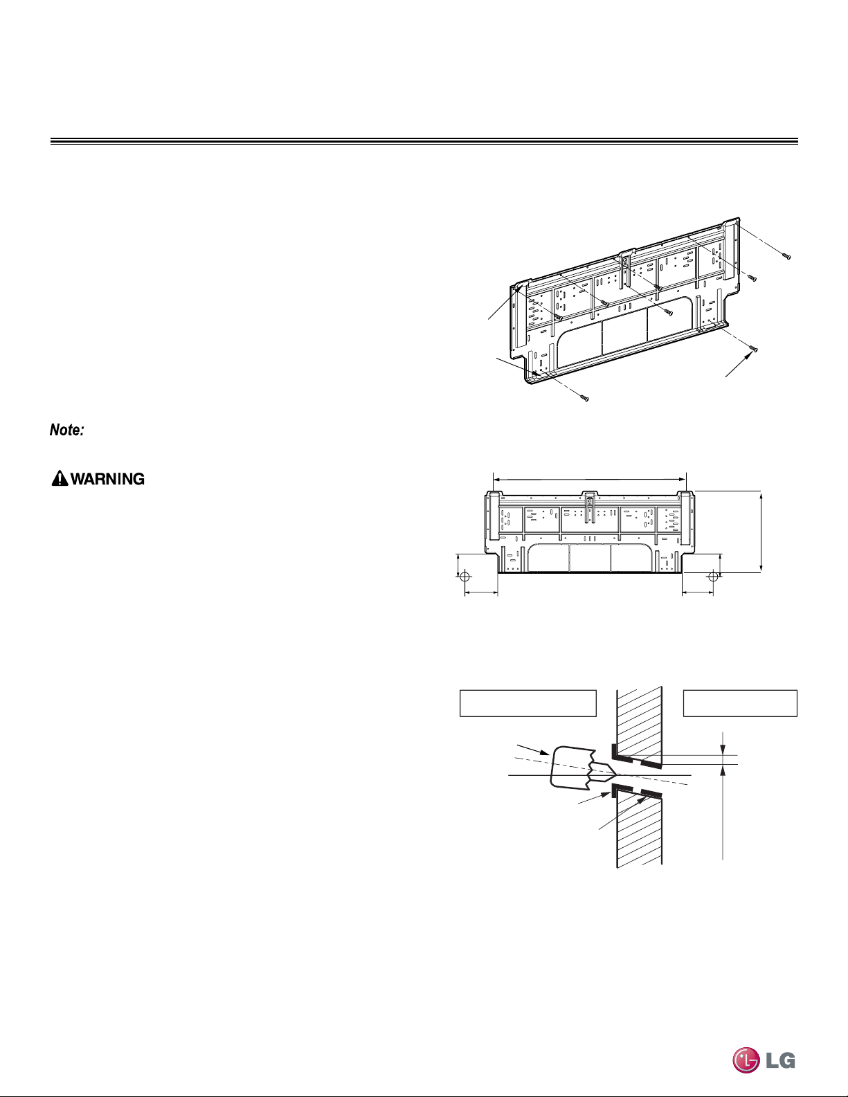
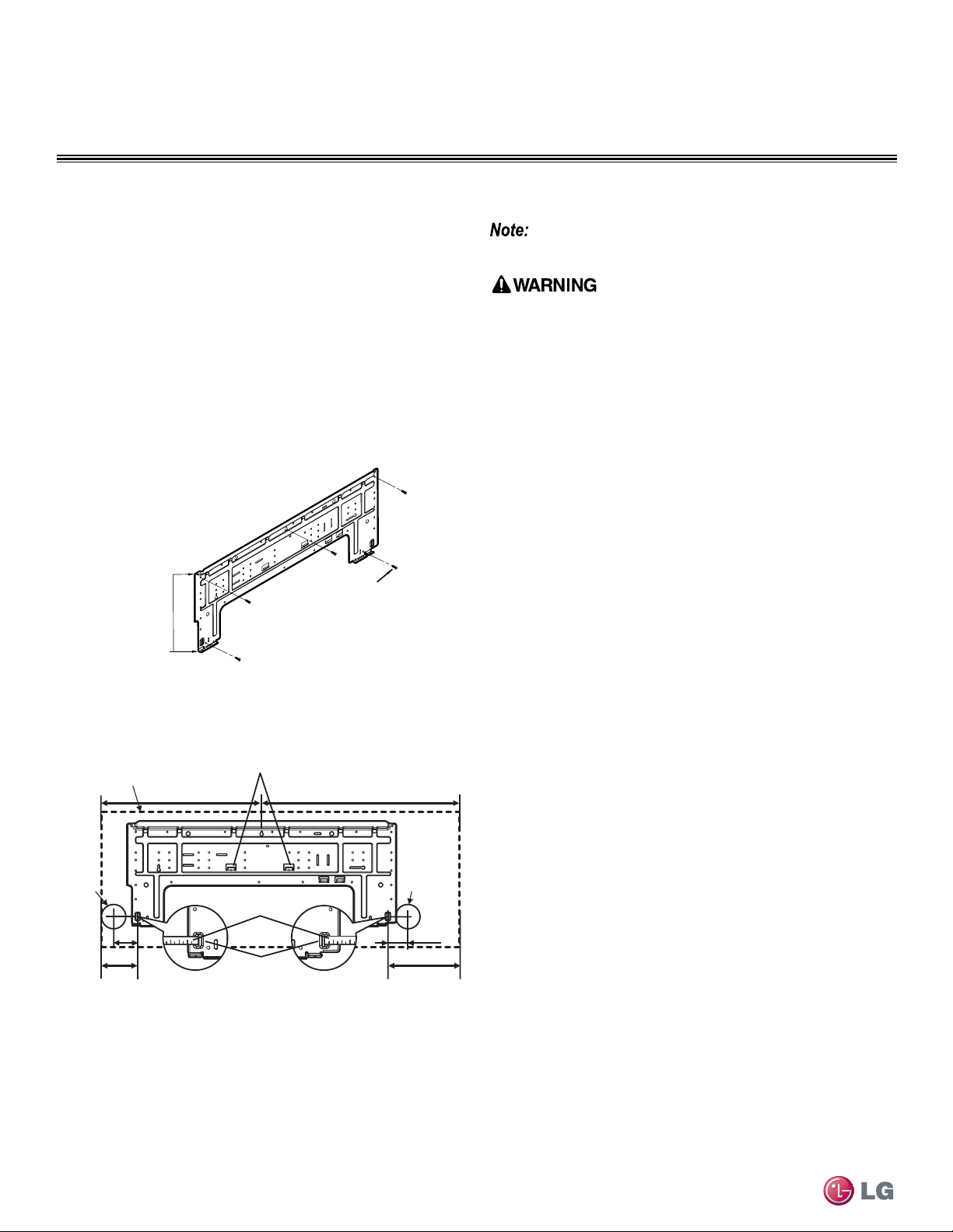
Mounting Installation Plate to Wall (240HSV3, HV3, HLV)
Follow the procedure and best practices when mounting the indoor
unit’s plate to a wall.
Procedure
1. Mount the installation plate horizontally by aligning the centerline
using a leveling tool (Figure 10).
2. Use type “A” screws when mounting the plating (these screws
come with the plate).
• If mounting the unit on concrete wall, use field supplied anchor
bolts.
3. Observe the left and right rear piping clearance when drilling into
the wall, as shown in Figure 11.
Installation Plate
Chassis
Hook
Type "A" Screws
Installation Plate
Left rear piping Right rear piping
1-11/16
4-11/32
4-11/16
Unit: Inch
1-11/16
30-
11/16
13-
3/16
Figure 10: Installation Plate - Mounting
Figure 11: Installation Plate - Mounting
Drilling Piping Hole in the Wall
Follow the left or right piping clearance recommendations as shown
in Figure 11.
1. Using a 2 5/8 (ø 65mm) inch hole core drill bit, drill a hole at
either the right or left side of the wall mounting (Figure 12).
• The slant of the hole should be 3/16” to 5/16” from level with the
slant being upward on the indoor unit side and downward on the
outdoor unit side.
2. Finish off the newly drilled hole as shown with bushing and
sleeve covering.
• Sleeve and bushing prevents damage to the tubing/bundling of the
piping.
(3/16"~5/16")
Indoor
WALL
Outdoor
Bushing
Core Drill
Sleeve
Figure 12: Drilling Piping Hole
See Refrigerant Piping Connections for Indoor Unit on
page 52 to proceed with piping.
Select location carefully. Unit should be anchored to a strong wall to pre-
vent unnecessary vibration.
• When choosing a location for the wall mount plate, be sure to take
into consideration routing of wiring for power outlets within the wall.
Contacting wiring can cause serious bodily injury, or death.
• Use caution when drilling holes through the walls for the purposes
of piping connections. Power wiring can cause serious bodily injury,
or death.
29
General Installation Guidelines
Due to our policy of continuous product innovation, some specifications may change without notification.
©LG Electronics U.S.A., Inc., Englewood Cliffs, NJ. All rights reserved. “LG” is a registered trademark of LG Corp.
GENERAL INSTALLATION GUIDELINES
Mounting of Indoor Unit Installation Plate
Mounting Installation Plate to Wall (Mega 090HEV, 120HEV)
A-Type
B-Type
Figure 14: Installation Plate Screws Type A, Type B - 120HEV
1. Confirm the position of screws between chassis and installation
plate (Figure 13 and Figure 14).
2. Mount the installation plate horizontally by aligning the centerline
using a leveling tool (Figure 15 and Figure 16).
3. Use provided screws when mounting the plating.
• If mounting the unit on concrete wall, use field supplied anchor
bolts.
4. Observe the left and right rear piping clearance when drilling
into the wall as shown in Figure 15 (090HEV) and Figure 16
(120HEV).
Installation Plate
Chassis
Hook
Type “A”
Ø2-
19/32
5-23/32
2-30/32
Right rear piping
Left rear piping
Installation Plate
Place a level on raised tab
Unit Outline
7-
18/32
7-
18/32
Unit: inch
14-
28/32
14-
28/32
Ø2-
19/32
090HEV
Installation Plate
Figure 13: Installation Plate Screw Type A - 090HEV
Figure 15: Installation Plate - 090HEV
Figure 16: Installation Plate - 120HEV
Ø2
-19/32
Right Rear
Piping
Left Rear
Piping
Installation Plate
Place a level on raised tab
Unit: Inch
9
-
21/32
7
5-
11/32
16-
8/32
18-
29/32
Unit Outline
120HEV
Ø2
-19/32
4-
27/32
Refer to “Drilling Piping Hole in the Wall” on page 28 as
you follow procedure to install plate.
Select location carefully. Unit should be anchored to a strong wall to pre-
vent unnecessary vibration.
• When choosing a location for the wall mount plate, be sure to take
into consideration routing of wiring for power outlets within the wall.
Contacting wiring can cause serious bodily injury, or death.
• Use caution when drilling holes through the walls for the purposes
of piping connections. Power wiring can cause serious bodily injury,
or death.
30
Single Zone High Efciency, Standard, Extended Pipe and Mega Wall Mount Installation Manual
Due to our policy of continuous product innovation, some specifications may change without notification.
©LG Electronics U.S.A., Inc., Englewood Cliffs, NJ. All rights reserved. “LG” is a registered trademark of LG Corp.
GENERAL INSTALLATION GUIDELINES
Mounting of Indoor Unit Installation Plate
Mounting Installation Plate to Wall (Mega 180HEV, 240HEV)
1. Confirm the position of screws between chassis and installation
plate (Figure 17).
2. Mount the installation plate horizontally by aligning the centerline
using a leveling tool (Figure 18).
3. Use provided screws when mounting the plating.
• If mounting the unit on concrete wall, use field supplied anchor
bolts.
4. Observe the left and right rear piping clearance when drilling into
the wall, as shown in Figure 18.
Refer to “Drilling Piping Hole in the Wall” on page 28 as
you follow procedure to install plate.
Unit: Inch
Ø
2
-19/32
Ø
2
-19/32
2 -11/16
2-3/16
Right rear
piping
Left rear
piping
Installation Plate
Measuring Tape
Measuring Tape
Hanger
Place a level on raised tab
Unit Outline
8-3/32
4-3/32
18
-3/32
22-
13/32
180HEV and
240HEV
Installation Plate
Chassis
Hook
Type "A" Screws
Figure 17: Installation Plate Showing Screw Locations
Figure 18: Installation Plate - 180HEV, 240HEV
Select location carefully. Unit should be anchored to a strong wall to pre-
vent unnecessary vibration.
• When choosing a location for the wall mount plate, be sure to take
into consideration routing of wiring for power outlets within the wall.
Contacting wiring can cause serious bodily injury, or death.
• Use caution when drilling holes through the walls for the purposes
of piping connections. Power wiring can cause serious bodily injury,
or death.
31
General Installation Guidelines
Due to our policy of continuous product innovation, some specifications may change without notification.
©LG Electronics U.S.A., Inc., Englewood Cliffs, NJ. All rights reserved. “LG” is a registered trademark of LG Corp.
GENERAL INSTALLATION GUIDELINES
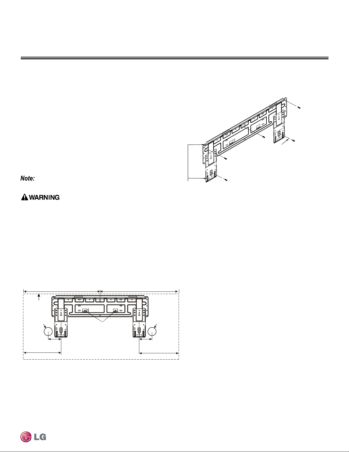
Follow the procedure and best practices when mounting the indoor
unit’s plate to a wall.
Procedure
1. Mount the installation plate horizontally by aligning the centerline
using a leveling tool (Figure 19).
2. Use type “A” screws when mounting the plating (these screws
come with the plate).
• If mounting the unit on concrete wall, use eld supplied anchor bolts.
3. Observe the left and right rear piping clearance when drilling into
the wall, as shown in Figure 20.
Mounting of Indoor Unit Installation Plate
Mounting Installation Plate to Wall (Mega 115V - HXV Models)
Installation Plate
Chassis
Hook
Type "A" Screws
Figure 19: Installation Plate - Mounting Mega 115V
Figure 20: Installation Plate - Mega 115V
Ø2-19/32
Right Rear
Piping
Left Rear
Piping
Installation Plate
Place a level on raised tab
Unit: Inch
9-
21/32
5-11/32
16-
8/32
18-
29/32
Unit Outline
Ø2-19/32
4-27/32
7
090HXV, 120HXV
Refer to “Drilling Piping Hole in the Wall” on page 28 as
you follow procedure to install plate.
Select location carefully. Unit should be anchored to a strong wall to pre-
vent unnecessary vibration.
• When choosing a location for the wall mount plate, be sure to take
into consideration routing of wiring for power outlets within the wall.
Contacting wiring can cause serious bodily injury, or death.
• Use caution when drilling holes through the walls for the purposes
of piping connections. Power wiring can cause serious bodily injury,
or death.
32
Single Zone High Efciency, Standard, Extended Pipe and Mega Wall Mount Installation Manual
Due to our policy of continuous product innovation, some specifications may change without notification.
©LG Electronics U.S.A., Inc., Englewood Cliffs, NJ. All rights reserved. “LG” is a registered trademark of LG Corp.
GENERAL INSTALLATION GUIDELINES
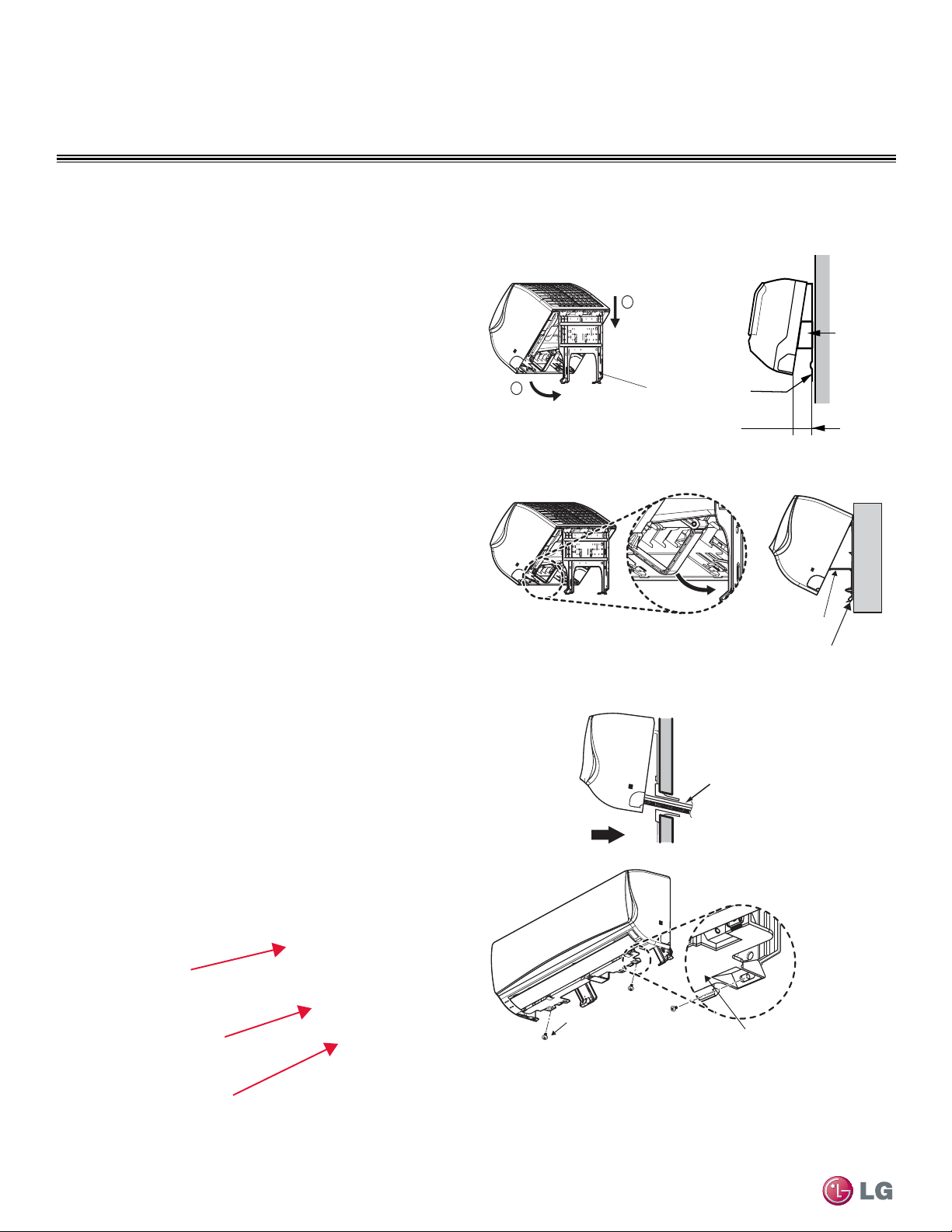
Mounting the Indoor Unit to the Installation Plate
Installation plate
Indoor unit
3”
Spacer
1
2
1. Hook the indoor unit onto the upper portion of the installation
plate ((1) Figure 21).
2. Engage the hooks at the top of the indoor unit with the upper
edge of the installation plate.
• Ensure that the hooks are properly seated on the installation plate
by moving it left and right.
3. Move the bottom of indoor unit towards the installation plate to
anchor to wall ((2) Figure 21).
• It helps to press the lower left and right sides of the unit against the
installation plate until the hooks engage into their slots.
• You will hear a clicking sound as the bottom attaches to the instal-
lation plate successfully.
4. Finish by inserting and tightening two type “C” screws into the
bottom of the installation plate (Figure 23).
• Pay attention to the positioning of the piping through any wall as
shown in the figure, as you insert the screws to the indoor unit.
Preparing for Piping/ Electrical Connection
1. To prepare indoor unit for piping, disengage bottom on indoor unit
from installation plate by reversing step 3 from previous
procedure.
• This step will separate the indoor unit’s bottom side from the wall
mount in order to route drain hose correctly. See Figure 24 for a
reference of the rear view of the indoor unit.
2. Swing drain hose holder (L-bracket) out and anchor as shown in
Figure 22, against installation plate.
3. Optionally, go to Refrigerant Piping Connections section
of this manual to continue with piping connections to the indoor
unit.
4. Optionally, go to Electrical Connections section of this manual to
continue with conduit/electrical wiring to the indoor unit.
Figure 21: Mounting Unit on Installation Plate
Figure 22: Mounting Unit on Installation Plate
Figure 23: Mounting Bottom of Unit to Installation Plate
Figure 24: Rear View of IDU
side of the indoor unit from the wall .
Installation Plate
Drain Hose
Holder
L-bracket
Type 'C' Screws
Bottom of
Indoor Unit
Indoor Unit
Piping
Through
Wall
Installation Plate
Drain Hose
Drain Hose Holder
Mounting of Indoor Unit
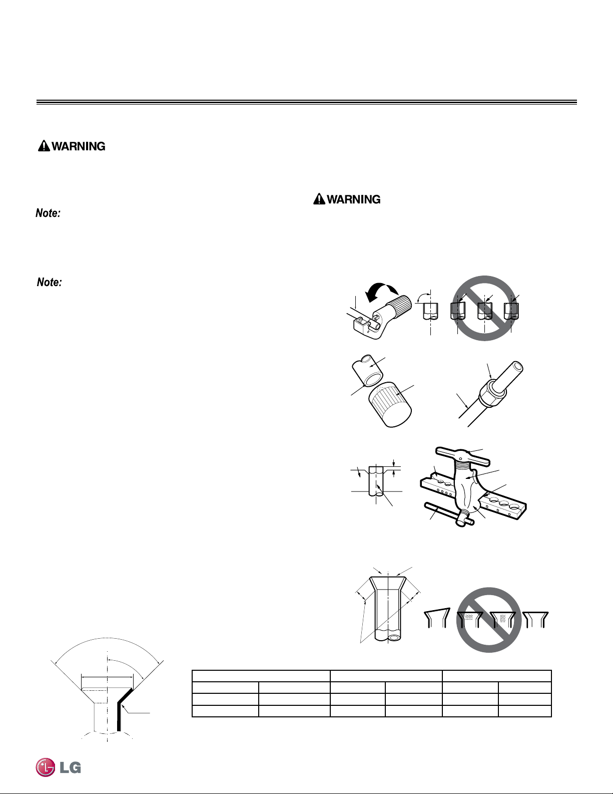
33
General Installation Guidelines
Due to our policy of continuous product innovation, some specifications may change without notification.
©LG Electronics U.S.A., Inc., Englewood Cliffs, NJ. All rights reserved. “LG” is a registered trademark of LG Corp.
GENERAL INSTALLATION GUIDELINES
Piping Preparation
• Do not allow the refrigerant to leak during brazing; if the refrigerant combusts, it generates a toxic gas.
• Do not braze in an enclosed location, and always test for gas leaks before / after brazing.
• After brazing, check for refrigerant gas leaks.
3. Flaring the pipe end.
• Use the proper size flaring tool to finish flared connections as
shown.
• ALWAYS create a 45° flare when working with R410A. See Warn-
ing on this page.
Creating a Flare Fitting
One of the main causes of refrigerant leaks is defective ared
connections. Create ared connections using the procedure below
(Figure 26).
1. Cut the pipe to length.
• Measure the distance between the indoor unit and the outdoor unit.
• Cut the pipes a little longer than measured distance.
• Cut the cable 4.9 ft longer than the pipe length.
2A. Remove the burrs.
• Completely remove all burrs from pipe ends.
• When removing burrs, point the end of the copper pipe down to
avoid introducing foreign materials in the pipe.
2B. Slide the flare nut onto the copper tube.
Copper
tube
90°
Slanted Uneven Rough
Pipe
Reamer
Point
down
Flare nut
Copper
tube
Bar
Copper pipe
Clamp handle
Red arrow
Cone
Yoke
Handle
Bar
"A"
Slanted
Inside is shiny with no scratches
Smooth
Even length
Damanged
surface
Cracked Uneven
thickness
Incorrect Flares
1.
2A. 2B.
3.
4.
4. Carefully inspect the flared pipe end.
• Compare the geometry with the figure to the right and dimensions
as detailed in Figure 25.
• If the flare is defective, cut it off and re-do procedure.
• If flare looks good, blow clean the pipe with dry nitrogen.
90°
2
45°
2
A
R=0.4~0.8
Figure 25: Dimensions of the Flare
Pipe “A” Thickness
Vapor (in. O.D.) Liquid (in. O.D.) Vapor (in.) Liquid (in.) Vapor (in.) Liquid (in.)
1/2 1/4 1/8 1/16 1/8 1/8
5/8 3/8 1/8 1/16 1/16 1/8
Table 11: Flared Connection Dimensions
Piping Preparation
1. Do not use kinked pipe caused by excessive bending in one
specific area on its length.
2. Braze the pipes to the service valve pipe stub of the outdoor unit.
When selecting are ttings, always use a 45° tting rated for use
with high pressure refrigerant R410A. Selected ttings must also
comply with local, state, or federal standards.
Figure 26: Creating a Flare Fitting
Single Zone Pipe Connections
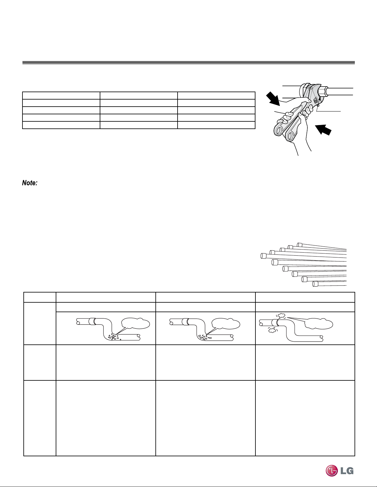
34
Single Zone High Efciency, Standard, Extended Pipe and Mega Wall Mount Installation Manual
Due to our policy of continuous product innovation, some specifications may change without notification.
©LG Electronics U.S.A., Inc., Englewood Cliffs, NJ. All rights reserved. “LG” is a registered trademark of LG Corp.
GENERAL INSTALLATION GUIDELINES
Union
Figure 27: Tightening the Flare Nuts.
Pipe size (Inches O.D.) Tightening torque (ft-lbs) Width of the are (A [inches])
1/4Ø 13.9 - 18 1/8
3/8Ø 24.5 - 30.3 1/8
1/2Ø 39.7 - 47.7 1/8
5/8Ø 45.5 - 59.2 1/16
Table 12: Tightening Torque for Flare Nuts.
Tightening the Flare Nuts
1. When connecting the flare nuts, coat the flare (inside and outside) with polyvinyl ether (PVE)
refrigeration oil only.
2. Initially hand tighten the flare nuts using three (3) or four (4) turns.
3. To finish tightening the flare nuts, use both a torque wrench and a backup wrench.
4. After all the piping has been connected and the caps have been tightened, check for refrigerant gas leaks.
Loosening the Flare Nuts
Always use two (2) wrenches to loosen the flare nuts.
Do not use polyolyester (POE) or any other type of mineral oil as a thread lubricant. These lubricants are not compatible with PVE oil used in
this system and create oil sludge leading to equipment damage and system malfunction.
Piping Preparation / Piping Materials and Handling
Pipes used for the refrigerant piping system must include the specified thickness, and the
interior must be clean.
While handling and storing, do not bend or damage the pipes, and take care not to contami-
nate the interior with dust, moisture, etc. See Table 13 for care of piping.
Dry Clean Airtight
Principles No moisture should be inside the piping. No dust should be inside the piping. No leaks should occur.
Problems
Caused
- Significant hydrolysis of refrigerant oil.
- Refrigerant oil degradation.
- Poor insulation of the compressor.
- System does not operate properly.
- EEVs, capillary tubes are clogged.
- Refrigerant oil degradation.
- Poor insulation of the compressor.
- System does not operate properly.
- EEVs and capillary tubes become
clogged.
- Refrigerant gas leaks / shortages.
- Refrigerant oil degradation.
- Poor insulation of the compressor.
- System does not operate properly.
Solutions
- Remove moisture from the piping.
- Piping ends should remain capped until
connections are complete.
- Do not install piping on a rainy day.
- Connect piping properly at the unit’s side.
- Remove caps only after the piping is
cut, the burrs are removed, and after
passing the piping through the walls.
- Evacuate system to a minimum of 500
microns and insure the vacuum holds at
that level for 24 hours
- Remove dust from the piping.
- Piping ends should remain capped until
connections are complete.
- Connect piping properly at the side of
the unit.
- Remove caps only after the piping is cut
and burrs are removed.
- Retain the cap on the piping when
passing it through walls, etc.
- Test system for air tightness.
- Perform brazing procedures that comply
with all applicable standards.
- Perform flaring procedures that comply
with all applicable standards.
- Perform flanging procedures that
comply with all applicable standards.
- Ensure that refrigerant lines are pressure
tested to 550 psig.
Moisture
Dust
Leaks
Figure 28: Keep Piping Capped While Storing
Table 13: Three Principles of Refrigerant Piping
Piping Materials and Handling
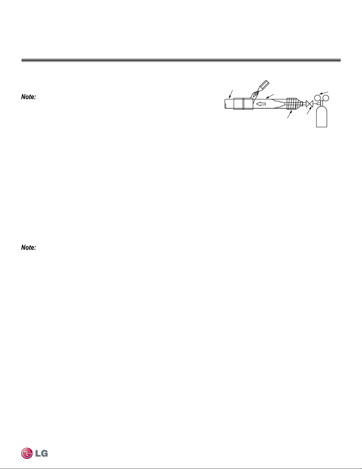
35
General Installation Guidelines
Due to our policy of continuous product innovation, some specifications may change without notification.
©LG Electronics U.S.A., Inc., Englewood Cliffs, NJ. All rights reserved. “LG” is a registered trademark of LG Corp.
GENERAL INSTALLATION GUIDELINES
Figure 29: Refrigerant Pipe Brazing.
Pressure-reducing
Valve
Valve
Taping
Nitrogen
Pipe to
be brazed
Refrigerant
Piping
It is imperative to keep the piping system free of contaminants and debris such as
copper burrs, slag, or carbon dust during installation.Contaminants can result in
mechanical failure of the system.
Brazing Practices
Piping Materials and Handling
All joints are brazed in the field. Duct Free System Single Zone Inverter refrigeration system components contain very small capillary tubes,
small orifices, electronic expansion valves, oil separators, and heat exchangers that can easily become blocked. Proper system operation
depends on the installer using best practices and utmost care while assembling the piping system.
• While brazing, use a dry nitrogen purge operating at a minimum pressure of three (3) psig and maintain a steady flow.
• Blow clean all pipe sections with dry nitrogen prior to assembly.
• Use a tubing cutter, do not use a saw to cut pipe. De-burr and clean all cuts before assembly.
• Store pipe stock in a dry place. Keep pipe capped and clean.
• Use adapters to assemble different sizes of pipe.
• Do not use flux, soft solder, or anti-oxidant agents.
• Use a 15% silver phosphorous copper brazing alloy to avoid overheating and produce good flow.
• Protect isolation valves, electronic expansion valves, and other heat-sensitive control components from excessive heat with a wet rag or a
heat barrier spray product
Refrigerant Piping System Insulation
All refrigerant piping, field-provided isolation ball valves, service valves, and elbows shall be completely insulated using closed cell pipe
insulation. The liquid and vapor lines must be insulated separately.
To prevent heat loss/heat gain through the refrigerant piping, all refrigerant piping including liquid lines and vapor lines shall be insulated sep-
arately. Insulation shall be a minimum 1/2″ thick, and thickness may need to be increased based on ambient conditions and local codes.
All insulation joints shall be glued with no air gaps. Insulation material shall fit snugly against the refrigeration pipe with no air space between
it and the pipe. Insulation passing through pipe hangers, inside conduit, and/or sleeves must not be compressed. Protect insulation inside
hangers and supports with a second layer. All pipe insulation exposed to the sun and outdoor elements shall be properly protected with PVC,
aluminum vapor barrier, or alternatively placed in a weather-resistant enclosure such as a pipe rack with a top cover; and meet local codes.
The design engineer should perform calculations to determine if the factory-supplied insulation jackets are sufficient to meet local codes and
avoid sweating. Add additional insulation if necessary. Mark all pipes at the point where the insulation jacket ends. Remove the jacket. Install
field provided insulation on the run-out and main trunk pipes first. Peel the adhesive glue protector slip from the insulation jacket and install
the clam-shell jacket over the fitting.
For specific insulation procedures, see Refrigerant Piping Connections section in this installation manual.
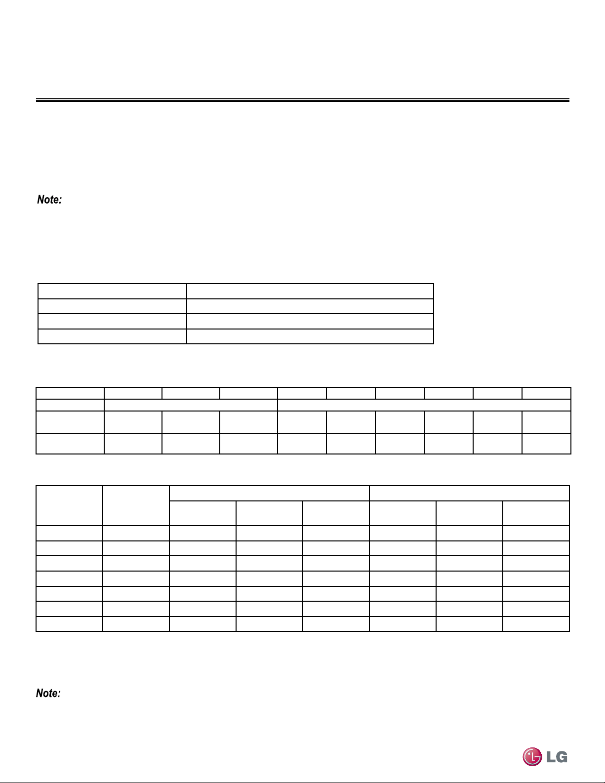
36
Single Zone High Efciency, Standard, Extended Pipe and Mega Wall Mount Installation Manual
Due to our policy of continuous product innovation, some specifications may change without notification.
©LG Electronics U.S.A., Inc., Englewood Cliffs, NJ. All rights reserved. “LG” is a registered trademark of LG Corp.
GENERAL INSTALLATION GUIDELINES
Piping Materials and Handling
Table 16: ACR Copper Tubing Dimensions and Physical Characteristics
1-4
Nominal Pipe
Outside
Diameter (in)
Actual Outside
Diameter (in)
Drawn Temper Annealed Temper
Nominal Wall
Thickness (in)
Weight (lb/ft)
Cubic ft per
Linear ft
Nominal Wall
Thickness (in)
Weight (lb/ft)
Cubic ft per
Linear ft
1/4 0.250 -- -- -- 0.030 0.081 .00020
3/8 0.375 0.030 0.126 .00054 0.032 0.134 .00053
1/2 0.500 0.035 0.198 .00101 0.032 0.182 .00103
5/8 0.625 0.040 0.285 .00162 0.035 0.251 .00168
3/4 0.750 0.042 0.362 .00242 0.042 0.362 .00242
7/8 0.875 0.045 0.455 .00336 0.045 0.455 .00336
1-1/8 1.125 0.050 0.655 .00573 0.050 0.655 .00573
1
All dimensions provided are in accordance with ASTM B280 – Standard.
2
Design pressure = 551 psig.
3
ACR Tubing is available as hard drawn or annealed (soft) and are suitable for use with R410A refrigerant.
4
The Copper Tube Handbook, 2010, Copper Development Association Inc., 260 Madison Avenue, New York, NY 10016.
• Commercially available piping often contains dust and other materials. Always blow it clean with a dry inert gas.
• Prevent dust, water or other contaminants from entering the piping during installation. Contaminants can cause
mechanical failure.
Selecting Field-Supplied Copper Tubing
Copper is the only approved refrigerant pipe material for use with Duct Free System Single Zone products, and LG recommends seamless
phosphorous deoxidized ACR type copper pipe, hard-drawn rigid type “K” or “L”, or annealed-tempered, copper pipe.
• Drawn temper (rigid) ACR copper tubing is available in sizes 3/8 through 2-1/8 inches (ASTM B 280, clean, dry, and capped).
• Annealed temper (soft) ACR copper tubing is available in sizes 1/4 through 2-1/8 inches (ASTM B 280, clean, dry, and capped).
Tube wall thickness should meet local code requirements and be approved for an operating pressure of 551 psi. If local code does not
specify wall thickness, LG suggests using tube thickness per table below. When bending tubing, try to keep the number of bends to a
minimum, and use the largest radii possible to reduce the equivalent length of installed pipe; also, bending radii greater than ten (10) pipe
diameters can minimize pressure drop. Be sure no traps or sags are present when rolling out soft copper tubing coils.
Table 14: ACR Copper Tubing Material
Type Seamless Phosphorous Deoxidized
Class UNS C12200 DHP
Straight Lengths H58 Temper
Coils O60 Temper
OD (in) 1/4 3/8 1/2 5/8 3/4 7/8 1-1/8 1-3/8 1-5/8
Material Rigid Type “K” or “L” and Soft ACR Acceptable Rigid Type “K” or “L” Only
Min. Bend
Radius (in)
.563 .9375 1.5 2.25 3.0 3.0 3.5 4.0 4.5
Min. Wall
Thickness (in)
.03 .03 .035 .040 .042 .045 .050 .050 .050
Table 15: Piping Tube Thicknesses
37
General Installation Guidelines
Due to our policy of continuous product innovation, some specifications may change without notification.
©LG Electronics U.S.A., Inc., Englewood Cliffs, NJ. All rights reserved. “LG” is a registered trademark of LG Corp.
GENERAL INSTALLATION GUIDELINES
Figure 30: Installing Piping Above and Below an Obstacle.
Above an obstacle.
3X
Below an obstacle.
Above an obstacle.
Below an obstacle.
Obstacles
When an obstacle, such as an I-beam or concrete T, is in the path
of the planned refrigerant pipe run, it is best practice to route the
pipe over the obstacle. If adequate space is not available to route
the insulated pipe over the obstacle, then route the pipe under the
obstacle. In either case, it is imperative the length of the horizontal
section of pipe above or below the obstacle be a minimum of three
(3) times the longest vertical rise (or fall) at either end of the
segment.
No Pipe Size Substitutions
Use only the pipe size recommended by this installation manual. Using a different size is prohibited and may result in a system malfunction or failure
to work at all.
Under normal operating conditions, the vapor pipe temperature of
a Duct Free System can vary as much as 280°F. With this large
variance in pipe temperature, the designer must consider pipe
expansion and contraction to avoid pipe and fitting fatigue failures.
Refrigerant pipe along with the insulation jacket form a cohesive
unit that expands and contracts together. During system operation,
thermal heat transfer occurs between the pipe and the surrounding
insulation.
If the pipe is mounted in free air space, no natural restriction to
movement is present if mounting clamps are properly spaced and
installed. When the refrigerant pipe is mounted underground in a
utility duct stacked among other pipes, natural restriction to linear
movement is present. In extreme cases, the restrictive force of
surface friction between insulating jackets could become so great
that natural expansion ceases and the pipe is “fixed” in place. In this
situation, opposing force caused by change in refrigerant fluid/vapor
temperature can lead to pipe/fitting stress failure.
The refrigerant pipe support system must be engineered to allow
free expansion to occur. When a segment of pipe is mounted
between two fixed points, provisions must be provided to allow pipe
expansion to naturally occur. The most common method is the
inclusion of expansion Loop or U-bends. Each segment of pipe has
a natural fixed point where no movement occurs. This fixed point is
located at the center point of the segment assuming the entire pipe
is insulated in a similar fashion. The natural fixed point of the pipe
segment is typically where the expansion Loop or U-bend should be.
Linear pipe expansion can be calculated using the following formula:
1. From Table 17 find the row corresponding with the actual length
of the straight pipe segment.
2. Estimate the minimum and maximum temperature of the pipe.
In the column showing the minimum pipe temperature, look up the
anticipated expansion distance. Do the same for the maximum
pipe temperature.
3. Calculate the difference in the two expansion distance values.
The result will be the anticipated change in pipe length.
Example:
A system is installed and the design shows that there is a 100 foot
straight segment of tubing between an indoor unit and the outdoor
unit. In heating, this pipe transports hot gas vapor to the indoor units
at 120 °F. In cooling, the same tube is a suction line returning refrig-
erant vapor to the outdoor unit at 40 °F. Look up the copper tubing
expansion at each temperature and calculate the difference.
Vapor Line
Transporting Hot Vapor: 100 ft. pipe at 120 °F = 1.40 in.
Transporting Suction Vapor: 100 ft. pipe at 40 °F = 0.40 in.
Anticipated Change in Length: 1.40 in. – 0.40 in. = 1.00 in.
Liquid Line
The liquid temperature remains relatively the same temperature; only
the direction of flow will reverse. Therefore, no significant change in
length of the liquid line is anticipated.
When creating an expansion joint, the joint height should be a
minimum of two times the joint width. Although different types of
expansion arrangements are available, the data for correctly sizing
an Expansion Loop is provided in Table 18. Use soft copper with
long radius bends on longer runs or long radius elbows for shorter
pipe segments. Using the anticipated linear expansion (LE) distance
calculated, look up the Expansion Loop or U-bend minimum design
dimensions. If other types of expansion joints are chosen, design
per ASTM B-88 Standards.
LE = C x L x (T
r
– T
a
) x 12
LE = Anticipated linear tubing expansion (in.)
C = Constant (For copper = 9.2 x 10
-6
in./in.°F)
L = Length of pipe (ft.)
T
R
= Refrigerant pipe temperature (°F)
T
a
= Ambient air temperature (°F)
12 = Inches to feet conversion (12 in./ft.)
Copper Expansion and Contraction
Piping Materials and Handling
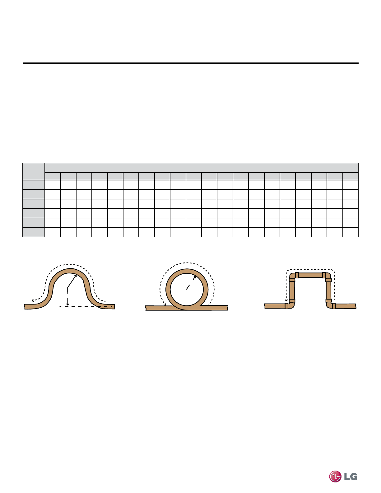
38
Single Zone High Efciency, Standard, Extended Pipe and Mega Wall Mount Installation Manual
Due to our policy of continuous product innovation, some specifications may change without notification.
©LG Electronics U.S.A., Inc., Englewood Cliffs, NJ. All rights reserved. “LG” is a registered trademark of LG Corp.
GENERAL INSTALLATION GUIDELINES
See table below for precalculated anticipated expansion for various pipe sizes and lengths of refrigerant tubing.
To find the anticipated expansion value:
1. From the table below, find the row corresponding with the actual feet of the straight pipe segment.
2. Estimate the minimum and maximum temperature of the pipe.
3. In the column showing the minimum pipe temperature, look up the anticipated expansion distance corresponding to the segment length.
Do the same for the maximum pipe temperature.
4. Calculate the difference in the two expansion distance values. The result will be the change in pipe length.
Pipe
Length
1
Fluid Temperature °F
35° 40° 45° 50° 55° 60° 65° 70° 75° 80° 85° 90° 95° 100° 105° 110° 115° 120° 125° 130°
10
0.04 0.04 0.05 0.06 0.06 0.07 0.08 0.08 0.09 0.09 0.10 0.10 0.11 0.11 0.11 0.12 0.13 0.14 0.15 0.15
20
0.08 0.08 0.10 0.12 0.13 0.14 0.15 0.16 0.17 0.18 0.19 0.20 0.21 0.22 0.22 0.23 0.26 0.28 0.29 0.30
30
0.12 0.12 0.15 0.18 0.20 0.21 0.23 0.24 0.26 0.27 0.29 0.30 0.32 0.33 0.32 0.35 0.39 0.42 0.44 0.45
40
0.16 0.16 0.20 0.24 0.26 0.28 0.30 0.32 0.34 0.36 0.38 0.40 0.42 0.44 0.43 0.46 0.52 0.56 0.58 0.60
50
0.20 0.20 0.25 0.30 0.33 0.35 0.38 0.40 0.43 0.45 0.48 0.50 0.53 0.55 0.54 0.58 0.65 0.70 0.73 0.75
60
0.24 0.24 0.30 0.36 0.39 0.42 0.45 0.48 0.51 0.54 0.57 0.60 0.63 0.66 0.65 0.69 0.78 0.84 0.87 0.90
Table 17: Linear Thermal Expansion of Copper Tubing in Inches
1
Pipe length baseline temperature = 0°F. "Expansion of Carbon, Copper and Stainless Steel Pipe," The Engineers' Toolbox, www.engineeringtoolbox.com.
Piping Materials and Handling
Figure 31: Coiled Expansion Loops and Offsets
Large Tubing U-bend (>3/4 in.) Loop Small Tubing U-bend (<3/4 in.)
R
L
R
L
L
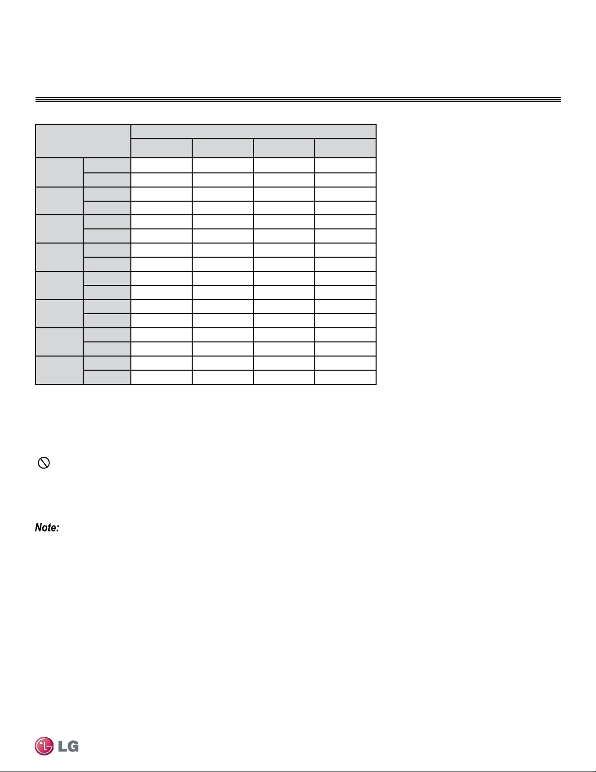
39
General Installation Guidelines
Due to our policy of continuous product innovation, some specifications may change without notification.
©LG Electronics U.S.A., Inc., Englewood Cliffs, NJ. All rights reserved. “LG” is a registered trademark of LG Corp.
GENERAL INSTALLATION GUIDELINES
Piping Materials and Handling
Anticipated Linear
Expansion (LE) (inch-
es)
Nominal Tube Size (OD) inches
1/4 3/8 1/2 3/4
1/2
R
1
6 7 8 9
L
2
38 44 50 59
1
R
1
9 10 11 13
L
2
54 63 70 83
1-1/2
R
1
11 12 14 16
L
2
66 77 86 101
2
R
1
12 14 16 19
L
2
77 89 99 117
2-1/2
R
1
14 16 18 21
L
2
86 99 111 131
3
R
1
15 17 19 23
L
2
94 109 122 143
3-1/2
R
1
16 19 21 25
L
2
102 117 131 155
4
R
1
17 20 22 26
L
2
109 126 140 166
Pipe Bends
When bending soft copper, use long radius bends. Refer to the "Radii of Coiled Expansion Loops and Developed Lengths of Expansion
Offsets” table for minimum radius specifications, as shown above.
In-line Refrigeration Components
Components such as oil traps, solenoid valves, filter-dryers, sight glasses, tee fittings, and other after-market accessories are not permitted
on the refrigerant piping system between the outdoor unit and the indoor unit.
Duct-free Single Zone systems are provided with redundant systems that assure oil is properly returned to the compressor. Sight-glasses and
solenoid valves may cause vapor to form in the liquid stream.
Over time, dryers may deteriorate and introduce debris into the system. The designer and installer should verify the refrigerant piping system
is free of traps, sagging pipes, sight glasses, filter dryers, etc.
Field-provided Isolation Ball Valves
LG allows the installation of field-supplied ball valves with Schrader ports at each indoor unit. Full-port isolation ball valves with Schrader
ports (positioned between valve and indoor unit) rated for use with R410A refrigerant should be used on both the liquid and vapor lines.
If valves are not installed and a single indoor unit needs to be removed or repaired, the entire system must be shut down and evacuated.
Position valves with a minimum distance of three (3) to six (6) inches of pipe on either side of the valve, and placed between six (6) and
twelve (12) inches from the run-out pipe to the upstream main pipe. If ball valves are installed closer to the indoor unit, a section of pipe
becomes a dead zone when the valves are closed where oil may accumulate.
Table 18: Radii of Coiled Expansion Loops and Developed Lengths of Expansion Offsets
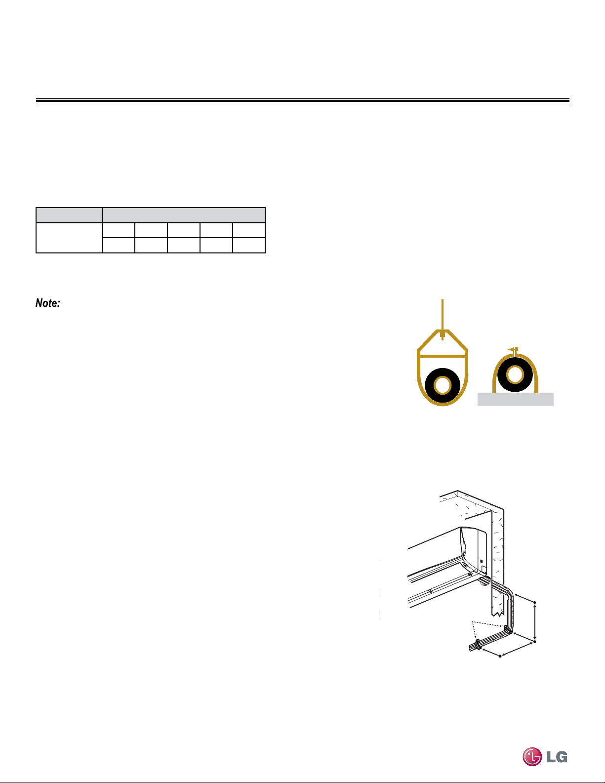
40
Single Zone High Efciency, Standard, Extended Pipe and Mega Wall Mount Installation Manual
Due to our policy of continuous product innovation, some specifications may change without notification.
©LG Electronics U.S.A., Inc., Englewood Cliffs, NJ. All rights reserved. “LG” is a registered trademark of LG Corp.
GENERAL INSTALLATION GUIDELINES
Using Elbows
Field-supplied elbows are allowed as long as they are designed for use with R410A refrigerant. The designer, however, should be cautious
with the quantity and size of fittings used, and must account for the additional pressure losses in equivalent pipe length calculation.
The equivalent pipe length of each elbow must be added to each pipe segment (Figure 32).
Piping Support, Elbow Usage
Pipe Supports
A properly installed pipe system should be adequately supported to avoid pipe sagging. Sagging pipes
become oil traps that lead to equipment malfunction.
Pipe supports should never touch the pipe wall; supports shall be installed outside (around) the
primary pipe insulation jacket (see Figure 33). Insulate the pipe first because pipe supports shall
be installed outside (around) the primary pipe insulation jacket. Clevis hangers should be used
with shields between the hangers and insulation. Field provided pipe supports should be de-
signed to meet local codes. If allowed by code, use fiber straps or split-ring hangers suspended
from the ceiling on all-thread rods (fiber straps or split ring hangers can be used as long as they
do not compress the pipe insulation). Place a second layer of insulation over the pipe insulation
jacket to prevent chafing and compression of the primary insulation within the confines of the
support pipe clamp.
Figure 33: Pipe Hanger Details
Figure 34: Typical Pipe Support Location—
Change in Pipe Direction
A properly installed pipe system will have sufficient supports to avoid pipes from sagging
during the life of the system. As necessary, place supports closer for segments where
potential sagging could occur. Maximum spacing of pipe supports shall meet local codes.
If local codes do not specify pipe support spacing, pipe shall be supported:
• Maximum of five feet (5′) on center for straight segments of pipe up to 3/4" outside
diameter size.
• Maximum of six feet (6′) on center for pipe up to one inch (1″) outside diameter size.
• Maximum of eight feet (8′) on center for pipe up to two inches (2″) outside diameter size.
Wherever the pipe changes direction, place pipe clamps within twelve (12) inches on
one side and within twelve to nineteen (12 to 19) inches of the bend on the other side as
shown in Figure 34.
A
B
Pipe
Clamps
A + B ≈ 12”–19”
Component Size (Inches)
Elbow (ft.)
1/4 3/8 1/2 5/8 3/4
0.5 0.6 0.7 0.8 1.2
Figure 32: Equivalent Piping Length for Piping Components
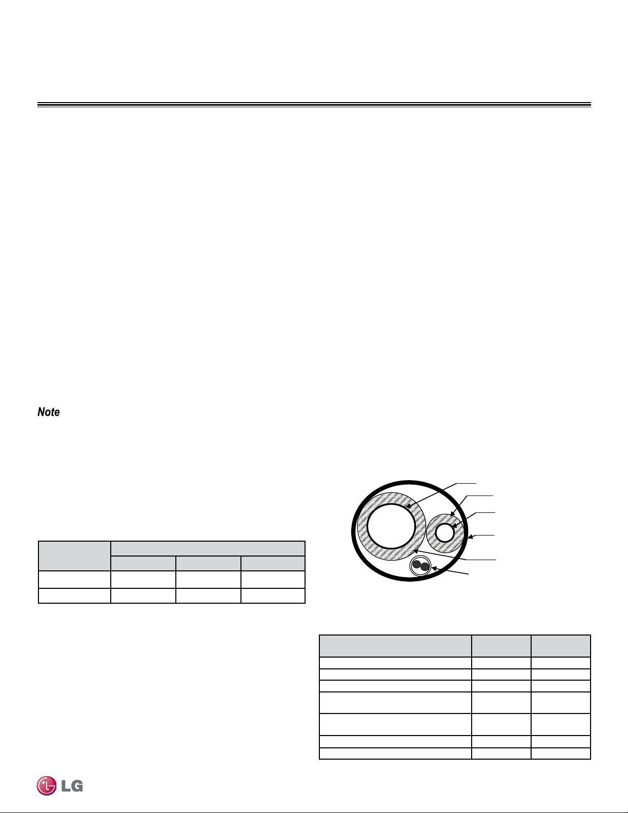
41
General Installation Guidelines
Due to our policy of continuous product innovation, some specifications may change without notification.
©LG Electronics U.S.A., Inc., Englewood Cliffs, NJ. All rights reserved. “LG” is a registered trademark of LG Corp.
GENERAL INSTALLATION GUIDELINES
Pipe Sleeves at Penetrations
LG requires that all pipe penetrations through walls, floors, and pipes buried underground be properly insulated and routed through an
appropriate wall sleeve of sufficient size to prevent compression of refrigerant pipe insulation and free movement of the pipe within the sleeve
(Figure 35). Underground refrigerant pipe shall be routed inside a protective sleeve to prevent insulation deterioration. Refer to Figure 36.
Figure 35: Pipe Sleeve Options.
Diameter of penetrations shall be determined by pipe diameter plus the thickness of the insulation.
Underground Refrigerant Piping
Refrigerant pipe installed underground should be routed inside a
vapor tight protective sleeve to prevent insulation deterioration and
water infiltration. Refrigerant pipe installed inside underground
casing must be continuous without any joints. Underground
refrigerant pipe must be located at a level below the frost line.
Figure 36: Typical Arrangement of Refrigerant Pipe and Cable(s) in a
Utility Conduit.
Table 19: Utility Conduit Sizes.
1
OD pipe diameter in inches; Values in parenthesis () indicate OD of pipe with insulation jacket.
2
Diameter of pipe with insulation. Thickness of pipe insulation is typical. Actual required thickness may
vary based on surrounding ambient conditions and should be calculated and specified by the design
engineer.
3
Insulation thickness (value in parenthesis) = 3/8 inch.
4
Insulation thickness (value in parenthesis) = 1 inch.
Liquid Pipe
1
Vapor Pipe
1
3/8 (1-1/8
2,3
) 1/2 (2.0
2,4
) 5/8 (2-1/8
2,4
)
1/4 (1.0)
3
4 4 4
3/8 (1-1/8)
3
4 4 4
Table 20: Heat Pump Unit Refrigerant Pipe Connections
(All Brazed Type)
Model
Liquid Conn.
(inches)
Vapor Conn.
(inches)
LSU091HSV3, LSU121HSV3
1/4 3/8
LSU181HSV3, LSU240HSV3
3/8 5/8
LSU307HV3, LSU360HV3
3/8 5/8
LSU240HLV, LSU300HLV,
LSU360HLV
3/8 5/8
LSU090HEV, LSU120HEV,
LSU090HXV, LSU120HXV
1/4 3/8
LSU180HEV
1/4 1/2
LSU240HEV
1/4 5/8
Refrigerant Piping System Layout
Vapor Line
Liquid Line
Min. 18 Gauge
Cable
Power/Communication
Pi
p
e Sleeve
Insulation Material
Insulation
Material
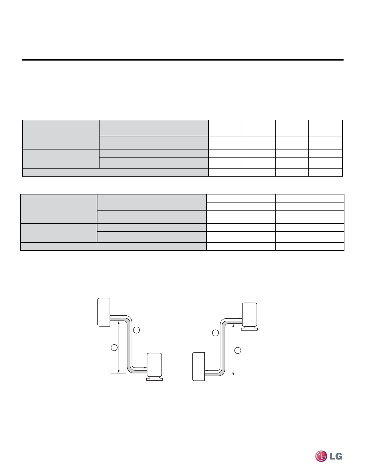
42
Single Zone High Efciency, Standard, Extended Pipe and Mega Wall Mount Installation Manual
Due to our policy of continuous product innovation, some specifications may change without notification.
©LG Electronics U.S.A., Inc., Englewood Cliffs, NJ. All rights reserved. “LG” is a registered trademark of LG Corp.
REFRIGERANT PIPING CONNECTIONS
Connection Limitations
Single zone systems consist of one outdoor unit and one indoor unit. One of the most critical elements of a single zone system is the refriger-
ant piping. Table 21- Table 24 list pipe length limits that must be followed in the design of a Single Zone Wall Mount refrigerant pipe system.
Refer to Figure 37 for maximum length and elevation of piping.
Table 21: Single Zone High Efciency Refrigerant Piping System Limitations
Pipe Length
(ELF = Equivalent Length of
pipe in Feet)
Longest total equivalent piping length
LS091HSV3 LS121HSV3 LS181HSV3 LS240HSV3
65.6 65.6 98.4 98.4
Distance between fittings and indoor units
or outdoor units
≥20 inches ≥20 inches ≥20 inches ≥20 inches
Elevation
(All Elevation Limitations are
Measured in Actual Feet)
If outdoor unit is above indoor unit
32.8 32.8 49.2 49.2
If outdoor unit is below indoor unit
32.8 32.8 49.2 49.2
Additional Refrigerant Needed (oz/ft)
0.22 0.22 0.38 0.38
Table 22: Single Zone Standard Refrigerant Piping System Limitations
Figure 37: Single Zone System Layout
Outdoor unit
Indoor unit
A
B
Outdoor unit
Indoor unit
A
B
Max Length = A
Max Elevation = B
Unit = Feet
Pipe Length
(ELF = Equivalent Length of
pipe in Feet)
Longest total equivalent piping length
LS307HV3 LS360HV3
98.4 98.4
Distance between fittings and indoor units
or outdoor units
≥20 inches ≥20 inches
Elevation
(All Elevation Limitations are
Measured in Actual Feet)
If outdoor unit is above indoor unit
49.2 49.2
If outdoor unit is below indoor unit
49.2 49.2
Additional Refrigerant Needed (oz/ft)
0.38 0.38
Refrigerant Piping System Limitations
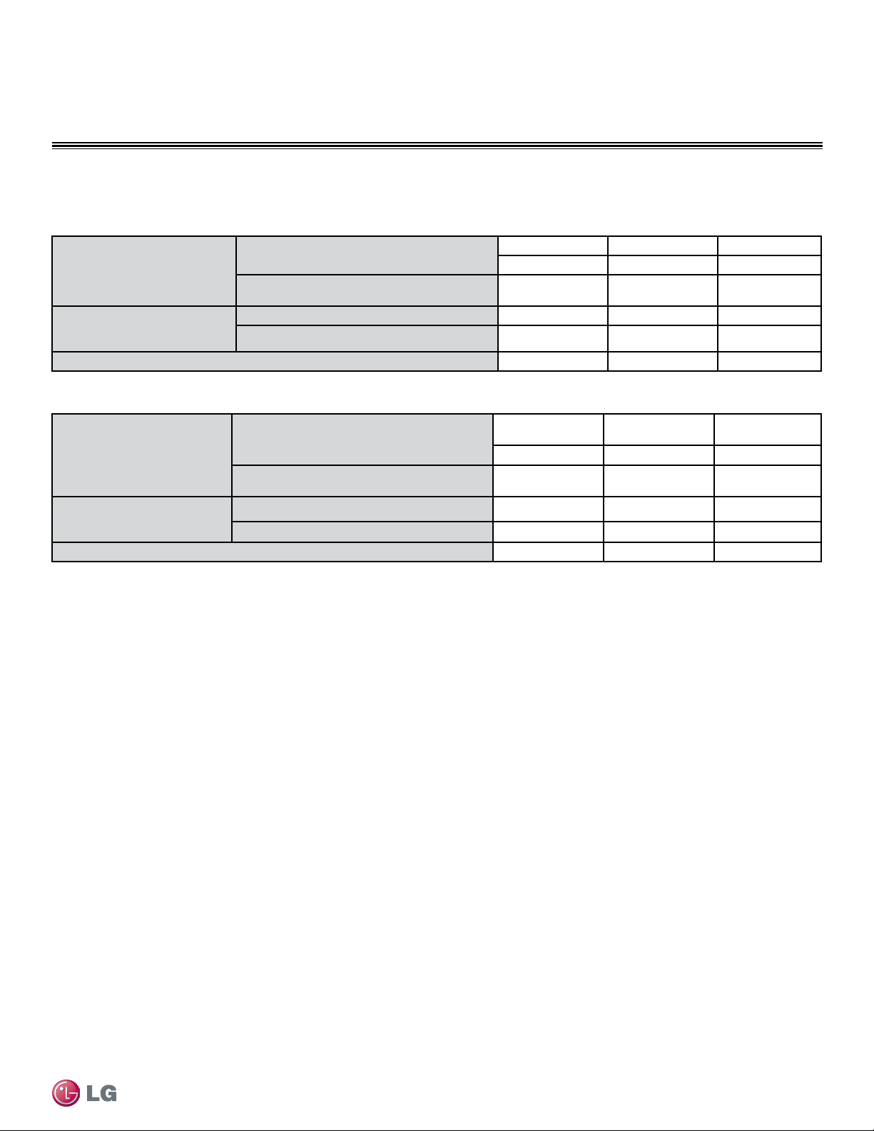
43
Refrigerant Piping Connections
Due to our policy of continuous product innovation, some specifications may change without notification.
©LG Electronics U.S.A., Inc., Englewood Cliffs, NJ. All rights reserved. “LG” is a registered trademark of LG Corp.
REFRIGERANT PIPING CONNECTIONS
Table 23: Single Zone Extended Pipe Refrigerant Piping System Limitations
Table 24: Single Zone Mega/Mega 115V Pipe Refrigerant Piping System Limitations
Pipe Length
(ELF = Equivalent Length of
pipe in Feet)
Longest total equivalent piping length
LS240HLV LS300HLV LS360HLV
164.0 164.0 164.0
Distance between fittings and indoor units
or outdoor units
≥20 inches ≥20 inches ≥20 inches
Elevation
(All Elevation Limitations are
Measured in Actual Feet)
If outdoor unit is above indoor unit
98.4 98.4 98.4
If outdoor unit is below indoor unit
98.4 98.4 98.4
Additional Refrigerant Needed (oz/ft)
0.38 0.38 0.38
Refrigerant Piping System Limitations
Pipe Length
(ELF = Equivalent Length of
pipe in Feet)
Longest total equivalent piping length
LSU090HEV/
LSU120HEV
LSU180HEV/
LSU240HEV
LSU090HXV/
LSU120HXV
49.2 65.6 49.2
Distance between fittings and indoor or
outdoor units
≥20 inches ≥20 inches ≥20 inches
Elevation
(All Elevation Limitations are
Measured in Actual Feet)
If outdoor unit is above indoor unit
22.9 32.8 23
If outdoor unit is below indoor unit
22.9 32.8 23
Additional Refrigerant Needed (oz/ft)
0.22 0.33 0.22
Connection Limitations - Continued
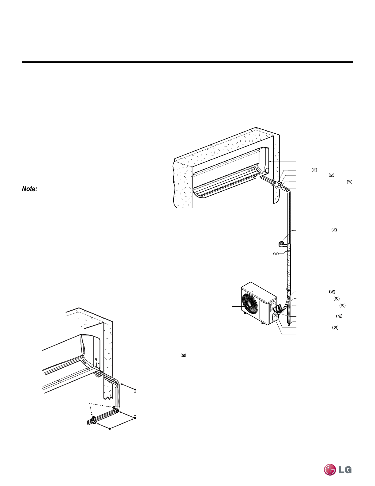
44
Single Zone High Efciency, Standard, Extended Pipe and Mega Wall Mount Installation Manual
Due to our policy of continuous product innovation, some specifications may change without notification.
©LG Electronics U.S.A., Inc., Englewood Cliffs, NJ. All rights reserved. “LG” is a registered trademark of LG Corp.
REFRIGERANT PIPING CONNECTIONS
Installation Overview
Vinyl tape (Wide)
• Apply after carrying out a
drainage test.
Saddle
Gas side piping
Liquid side piping
Additional drain pipe
Vinyl tape (Narrow)
Drain Hose
Base Plate
Air Outlet
Air Inlet
Connecting cable
Tubing Cover
Sleeve
Bushing-Sleeve
Putty(Gum Type Sealant)
Bend the pipe as closely
on the wall as possible,
but be careful that it
doesn't break.
Installation plate
Installation Overview
Additional accessories/parts/tools that will be
needed for installation but are not provided by LG.
Figure 38: Installation and Piping Connection Overview
Figure 39: Pipe Support Lengths - Outdoors
Installation
Duct Free Single Zone Wall Mounts are a one-to-one sys-
tem. There is a direct piping connection between the outdoor
unit and the indoor unit. Figure 38 Illustrates the basic pipe
connections between the outdoor and indoor unit. Refer back
to this illustration as you proceed with pipe connections, This
illustration shows the indoor unit being installed at a higher
position than the outdoor unit. However, should you install the
outdoor unit at a higher position than the indoor unit, the basic
pipe connections should be the same.
Refer back to the tables within the “Connection Limita-
tions” section, on the previous page, for specific length
limitations in conjunction with outdoor unit and indoor unit
positioning.
A
B
Pipe
Clamps
A + B ≈ 12”–19”
• As you proceed with the piping connections be sure to adhere
to pipe support spacing lengths as shown in Figure 39 below.
Refer back to “Pipe Supports” section for in-depth information
regarding using elbows, clamps and pipe supporting materials.
• Always adhere to local codes regarding piping and accurate
support spacing along the outdoor pipe line.
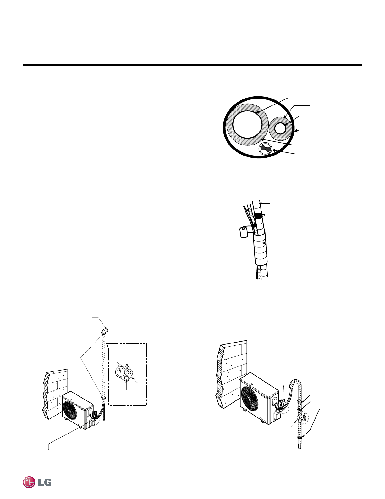
45
Refrigerant Piping Connections
Due to our policy of continuous product innovation, some specifications may change without notification.
©LG Electronics U.S.A., Inc., Englewood Cliffs, NJ. All rights reserved. “LG” is a registered trademark of LG Corp.
REFRIGERANT PIPING CONNECTIONS
Directional Pipe Formation
Drain hose
Vinyl tape(narrow)
Pipe
Wrap with
vinyl tape(wide)
Bundling Piping
Pipe Bundling
See Figure 40 for proper pipe and cable bundling. Note the placement
of the piping along with the necessary insulation material.
1. Be sure to wrap each pipe with proper insulation material.
2. Secure the piping by wrapping vinyl tape around the pipe.
• Use the narrow size tape for wrapping the actual pipe.
3. You can include the drain hose within the bundled piping and wrap all
of them together using the wider vinyl tape as shown in Figure 41.
• The end of the drain hose outlet must be routed above the ground.
Indoor Unit Installed Above Outdoor Unit
1. Refer to Figure 42 while following the procedures below.
2. Tape the piping, drain hose and connecting cable from down to up.
3. Secure the taped piping along the exterior wall using pipe
clamps.
4. Create trap above the electrical connections cover, in order to pre-
vent water from penetrating electrical components and wiring.
Indoor Unit Installed Below Outdoor Unit
1. Refer to Figure 43 while following the procedures below.
2. Tape the piping, drain hose and connection cable from down to up.
3. Secure the taped piping along the exterior wall using pipe
clamps.
4. Create trap above the electrical connections cover, in order to
prevent water from entering the room.
Figure 40: Cutaway of Proper Pipe and Cable Bundling
Figure 41: Bundling and Taping
Taping
Pipe Clamps
to Secure Pipe
Against Wall
Drain hose
Pipings
Connecting cable
Seal small openings
around pipings with a
gum type sealant.
Trap is required to prevent water
from entering into electrical parts.
Indoor Unit Installed ABOVE
Outdoor Unit - Piping/Trap
Figure 42: IDU Above ODU - Piping and Trap
Seal a small opening
around the pipings
with gum type sealant.
Trap
Trap
Indoor Unit Installed BELOW
Outdoor Unit - Piping/Trap
Pipe Clamps
to Secure Pipe
Against Wall
Figure 43: IDU Below ODU - Piping and Trap
Vapor Line
Liquid Line
Min. 18 Gauge
Cable
Power/Communication
Pi
p
e Sleeve
Insulation Material
Insulation
Material
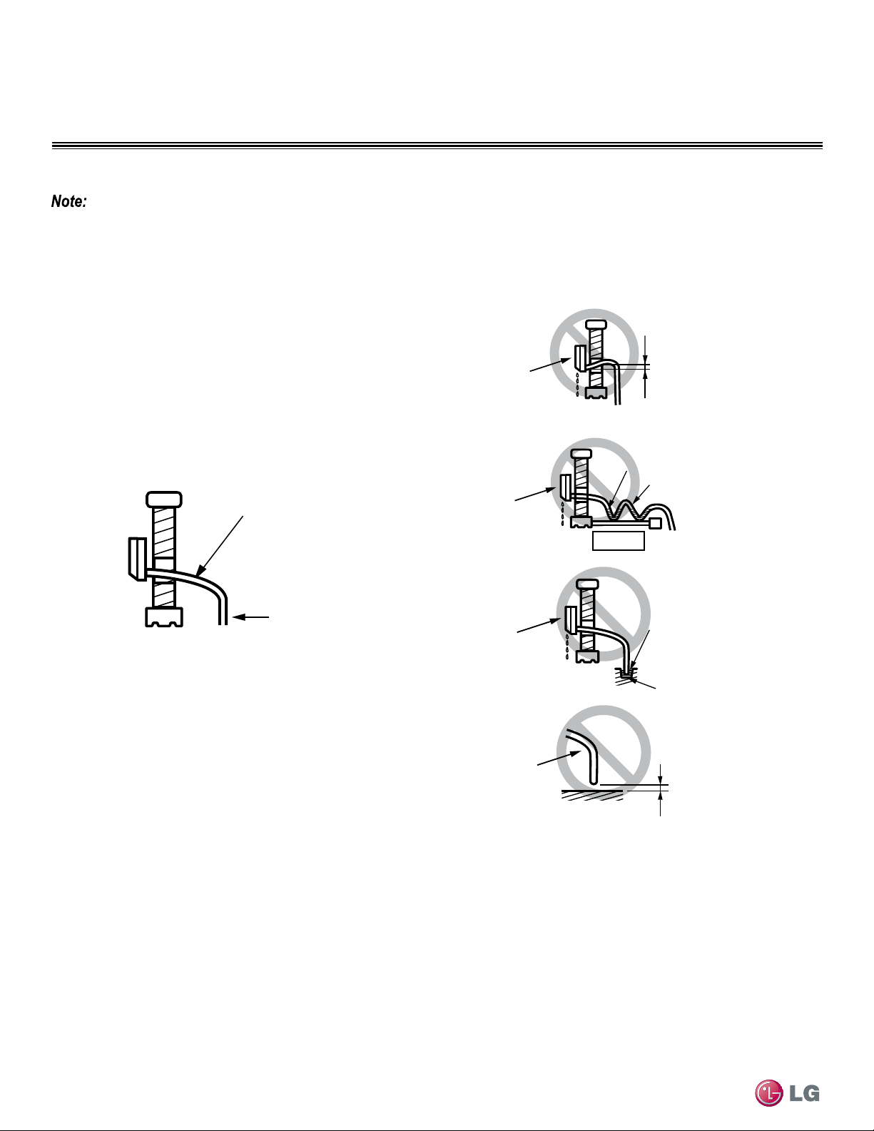
46
Single Zone High Efciency, Standard, Extended Pipe and Mega Wall Mount Installation Manual
Due to our policy of continuous product innovation, some specifications may change without notification.
©LG Electronics U.S.A., Inc., Englewood Cliffs, NJ. All rights reserved. “LG” is a registered trademark of LG Corp.
REFRIGERANT PIPING CONNECTIONS
Drain Hose
Drain Hose Guidelines
Refer to the diagrams below and follow proper installation and the running of the drain hose along the pipe installation line to avoid leakage. Once
drain hose is set in place, always follow with evacuation and leakage testing of all piping to be sure all piping is properly sealed. Re-check and retest
as necessary.
Drain hose is routed from the indoor unit through the structure
(wall) to the outdoor. It should slope at an angle where it is high-
er at the indoor unit and lower toward the outdoor area, thereby
letting gravity push any condensation down and out. See Figure
44 for proper drainage slope. Avoid piping the drain hose as
shown in Figure 45. These methods are incorrect and can cause
leakage at the indoor unit site.
Downward slope
to outdoor
for proper drainage
Indoor
Unit
Piping
Correct Drainage Slope
Figure 44: Correct Slope Angle for Drain Hose
Upward slope
to outdoor
can cause indoor
leaks!
Water
leakage
Accumulated
drain water
Air
Waving
Water
leakage
Indoor Unit
Indoor Unit
Incorrect Drainage Setup
Tip of drain hose
dipped in water
Water
leakage
Ditch
Less than
2 Inch gap from ground
Indoor Unit
Drain Hose
Figure 45: Correct Slope Angle for Drain Hose
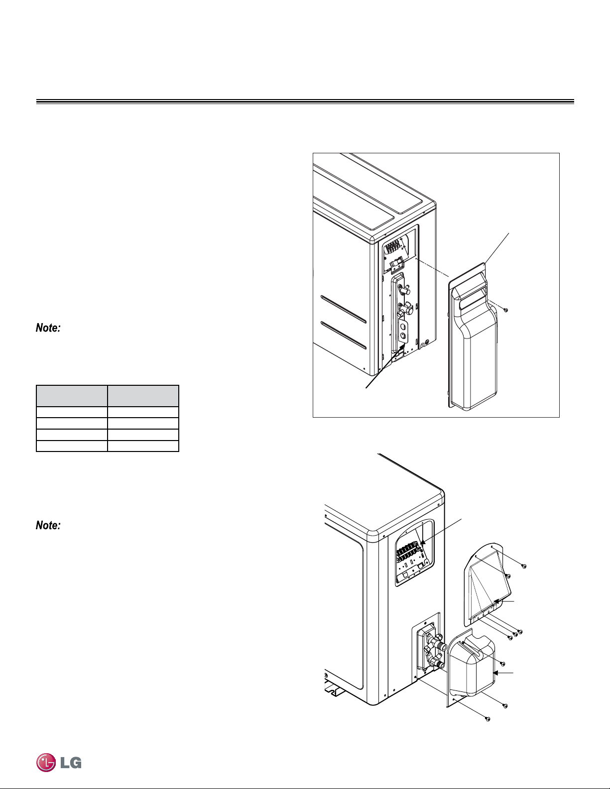
47
Refrigerant Piping Connections
Due to our policy of continuous product innovation, some specifications may change without notification.
©LG Electronics U.S.A., Inc., Englewood Cliffs, NJ. All rights reserved. “LG” is a registered trademark of LG Corp.
REFRIGERANT PIPING CONNECTIONS
Outdoor Unit Connections
Single Zone Wall Mount Outdoor Unit Connections (HSV3, HV3, HLV)
1. Remove the tubing cover by loosening the fastening screws.
See Figure 46 for HSV3 model and Figure 47 for HV3, HLV models.
2. Align the center of the refrigerant pipe and corresponding
connection as shown in Figure 48 (on the next page).
3. Refer to Figure 49 (for HSV3) and Figure 50 (for HV3, HLV) for
correct liquid and gas pipe attachment onto outdoor unit.
4. Place a couple of drops of refrigerant oil on the opening rim of the
flare before assembling. Ensure you do not add any
contaminants. Tighten the flare nut initially by hand.
5. Finish tightening the flare nut with a torque wrench until the
wrench clicks. Follow torque guidelines in Table 25. See Figure
49 for HSV3 model and Figure 50 for HV3, HLV models for cor-
rect connection points.
Figure 46: Outdoor Unit Connection Cover Removal (HSV3)
Figure 47: Outdoor Unit Connection Cover Removal (HV3, HLV)
Tubing Cover
Bracket for
Main Power Cables
When tightening the are nut with a torque wrench, ensure the direc-
tion for tightening follows the arrow on the wrench.
Table 25: Torque Wrench Tightening
Outside Diame-
ter (inches)
Torque (lbs-ft)
1/4
13-18
3/8
24.6-30.4
1/2
39.8-47.7
5/8
45.6-59.3
HSV3
Tubing
Cover
Conduit
Cover
Terminal Block
HV3, HLV
Do not thread liquid or gas piping through bracket used to hold main pow-
er cables (for HSV3 model).
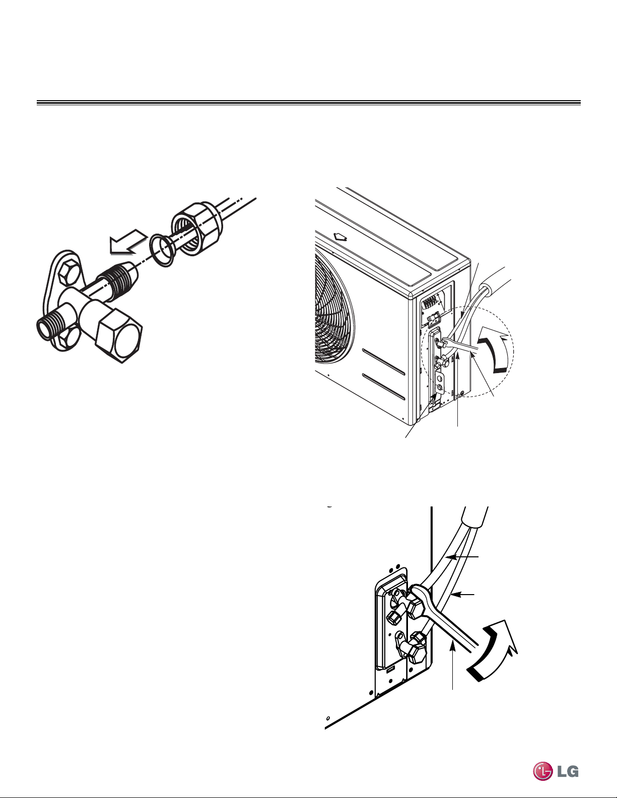
48
Single Zone High Efciency, Standard, Extended Pipe and Mega Wall Mount Installation Manual
Due to our policy of continuous product innovation, some specifications may change without notification.
©LG Electronics U.S.A., Inc., Englewood Cliffs, NJ. All rights reserved. “LG” is a registered trademark of LG Corp.
REFRIGERANT PIPING CONNECTIONS
Single Zone Wall Mount Outdoor Unit Connections
(HSV3, HV3, HLV) - Continued
Outdoor Unit Connections
Figure 48: Pipe Attachment Figure 49: Outdoor Unit Piping Connection (HSV3)
Figure 50: Outdoor Unit Piping Connection (HV3, HLV)
Outdoor Unit
Gas Piping
(Larger diameter)
Liquid Piping
(Smaller diameter)
Torque Wrench
Bracket for
Main Power
Cables
HSV3
Outdoor Unit
Torque wrench
Liquid Piping
(Smaller diameter)
Gas Piping
(Larger diameter)
HV3, HLV
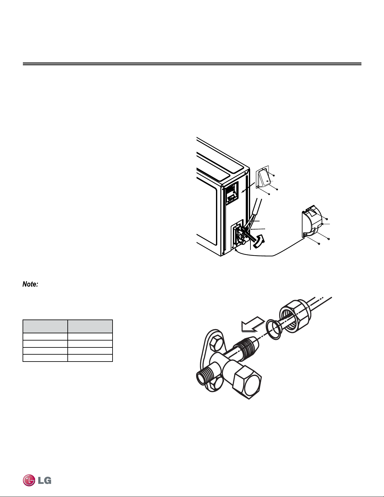
49
Refrigerant Piping Connections
Due to our policy of continuous product innovation, some specifications may change without notification.
©LG Electronics U.S.A., Inc., Englewood Cliffs, NJ. All rights reserved. “LG” is a registered trademark of LG Corp.
REFRIGERANT PIPING CONNECTIONS
Single Zone Wall Mount Outdoor Unit Connections
(090HEV, 090HXV, 120HEV, 120HXV)
1. Remove the tubing cover by loosening the fastening screws (Figure 51).
2. Align the center of the refrigerant pipe and corresponding
connection as shown in Figure 52.
3. Refer to Figure 51 for correct liquid and gas pipe attachment onto
outdoor unit.
4. Place a couple of drops of refrigerant oil on the opening rim of the
flare before assembling. Ensure you do not add any
contaminants. Tighten the flare nut initially by hand.
5. Finish tightening the flare nut with a torque wrench until the wrench
clicks. Follow torque guidelines in Table 26.
Outdoor Unit Connections
Figure 51: Outdoor Unit Cover Removal and Piping Connection
(090HEV, 090HXV, 120HEV, 120HXV)
To rque wrench
Conduit Cover
090HEV, 090HXV
120HEV, 120HXV
Tubing Cover
Gas Piping
(Larger diameter)
Liquid Piping
(Smaller diameter)
When tightening the are nut with a torque wrench, ensure the direc-
tion for tightening follows the arrow on the wrench.
Table 26: Torque Wrench Tightening
Outside Diame-
ter (inches)
Torque (lbs-ft)
1/4
13-18
3/8
24.6-30.4
1/2
39.8-47.7
5/8
45.6-59.3
Figure 52: Pipe Attachment
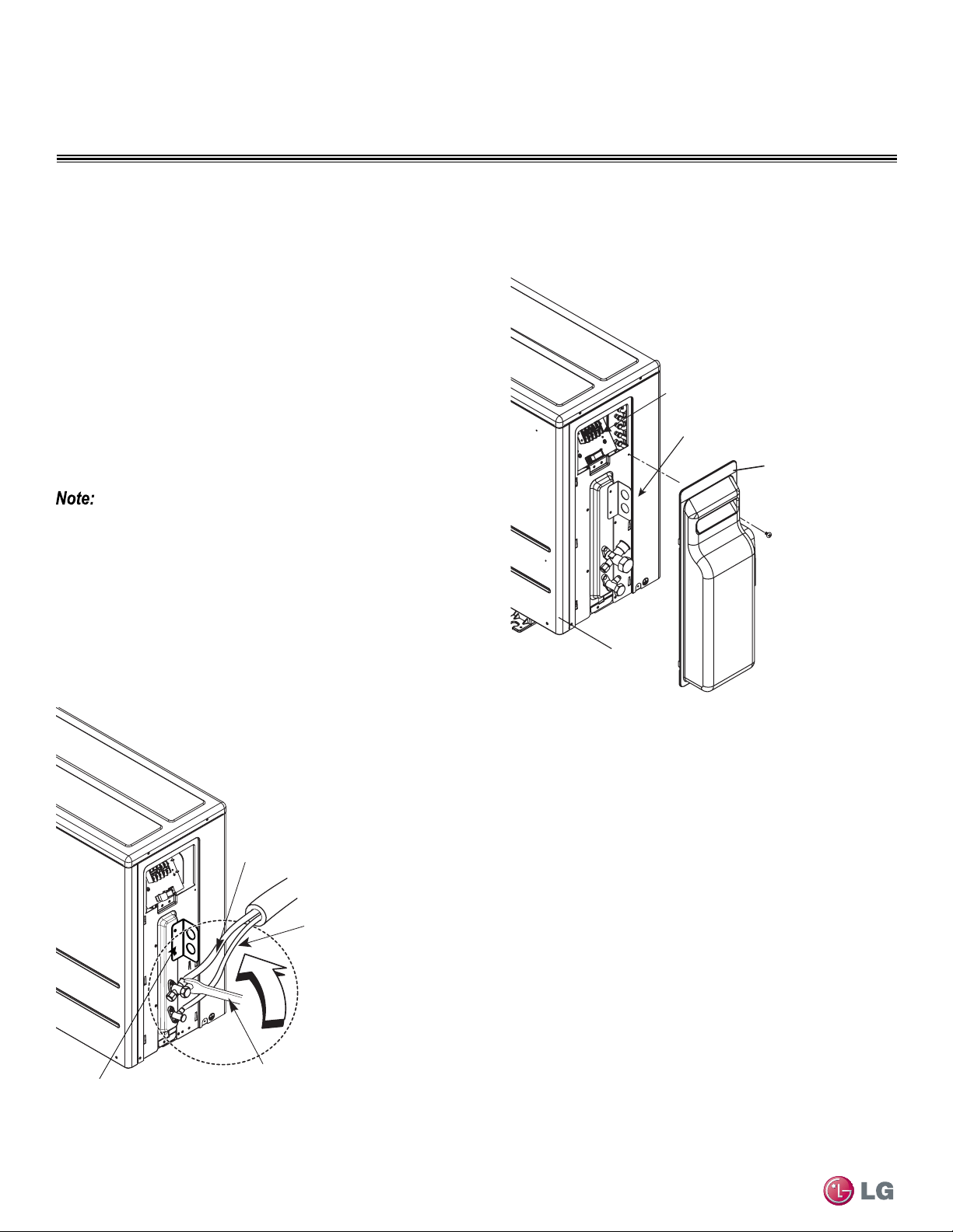
50
Single Zone High Efciency, Standard, Extended Pipe and Mega Wall Mount Installation Manual
Due to our policy of continuous product innovation, some specifications may change without notification.
©LG Electronics U.S.A., Inc., Englewood Cliffs, NJ. All rights reserved. “LG” is a registered trademark of LG Corp.
REFRIGERANT PIPING CONNECTIONS
Single Zone Wall Mount Outdoor Unit Connections (180HEV)
1. Remove the tubing cover by loosening the fastening screws (Figure 53).
2. Align the center of the refrigerant pipe and corresponding
connection as shown in Figure 52 (on previous page).
3. Refer to Figure 54 for correct liquid and gas pipe attachment onto
outdoor unit.
4. Place a couple of drops of refrigerant oil on the opening rim of the
flare before assembling. Ensure you do not add any
contaminants. Tighten the flare nut initially by hand.
5. Finish tightening the flare nut with a torque wrench until the wrench
clicks. Follow torque guidelines in Table 26 (on previous page).
Figure 53: Outdoor Unit Connection Cover Removal (180HEV)
Figure 54: Outdoor Unit Piping Connection (180HEV)
Terminal Block
Bracket for
Main Power Cables
Tubing
Cover
180HEV
Screw
Outdoor Unit
Torque wrench
Gas Piping
Liquid Piping
Bracket for Main
Power Cables
(Larger diameter)
(Smaller diameter)
180HEV
Do not thread liquid or gas piping through bracket used to hold main
power cables.
Outdoor Unit Connections
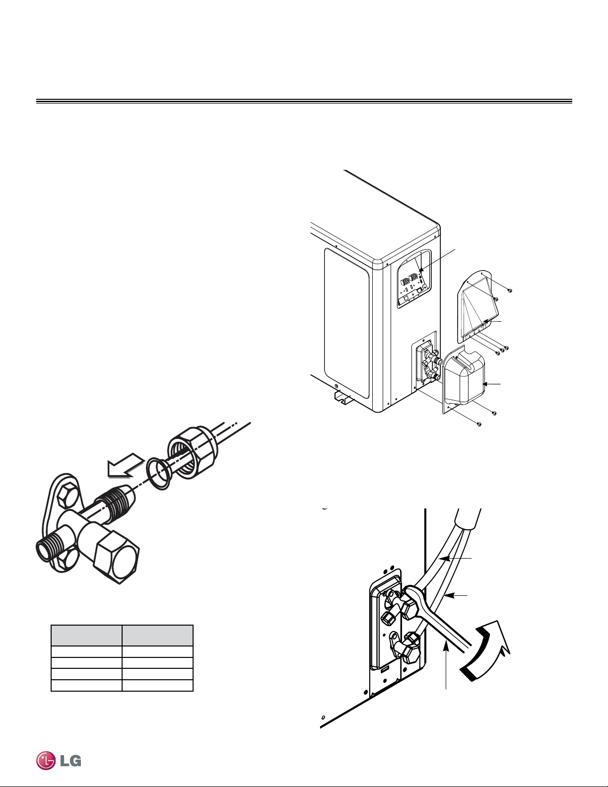
51
Refrigerant Piping Connections
Due to our policy of continuous product innovation, some specifications may change without notification.
©LG Electronics U.S.A., Inc., Englewood Cliffs, NJ. All rights reserved. “LG” is a registered trademark of LG Corp.
REFRIGERANT PIPING CONNECTIONS
Outdoor Unit
Torque wrench
Liquid Piping
(Smaller diameter)
Gas Piping
(Larger diameter)
Single Zone Wall Mount Outdoor Unit Connections (240HEV)
Tubing
Cover
Conduit Panel
Cover
Terminal Block
240HEV
Screw
Outdoor Unit Connections
Figure 55: Outdoor Unit Cover Removal (240HEV)
Figure 57: Outdoor Unit Piping Connection (240HEV)
1. Remove the tubing cover by loosening the fastening screws (Figure 55).
2. Align the center of the refrigerant pipe and corresponding
connection as shown in Figure 56.
3. Refer to Figure 57 for correct liquid and gas pipe attachment onto
outdoor unit.
4. Place a couple of drops of refrigerant oil on the opening rim of the
flare before assembling. Ensure you do not add any
contaminants. Tighten the flare nut initially by hand.
5. Finish tightening the flare nut with a torque wrench until the wrench
clicks. Follow torque guidelines in Table 27.
Figure 56: Pipe Attachment
Table 27: Torque Wrench Tightening
Outside Diame-
ter (inches)
Torque (lbs-ft)
1/4
13-18
3/8
24.6-30.4
1/2
39.8-47.7
5/8
45.6-59.3
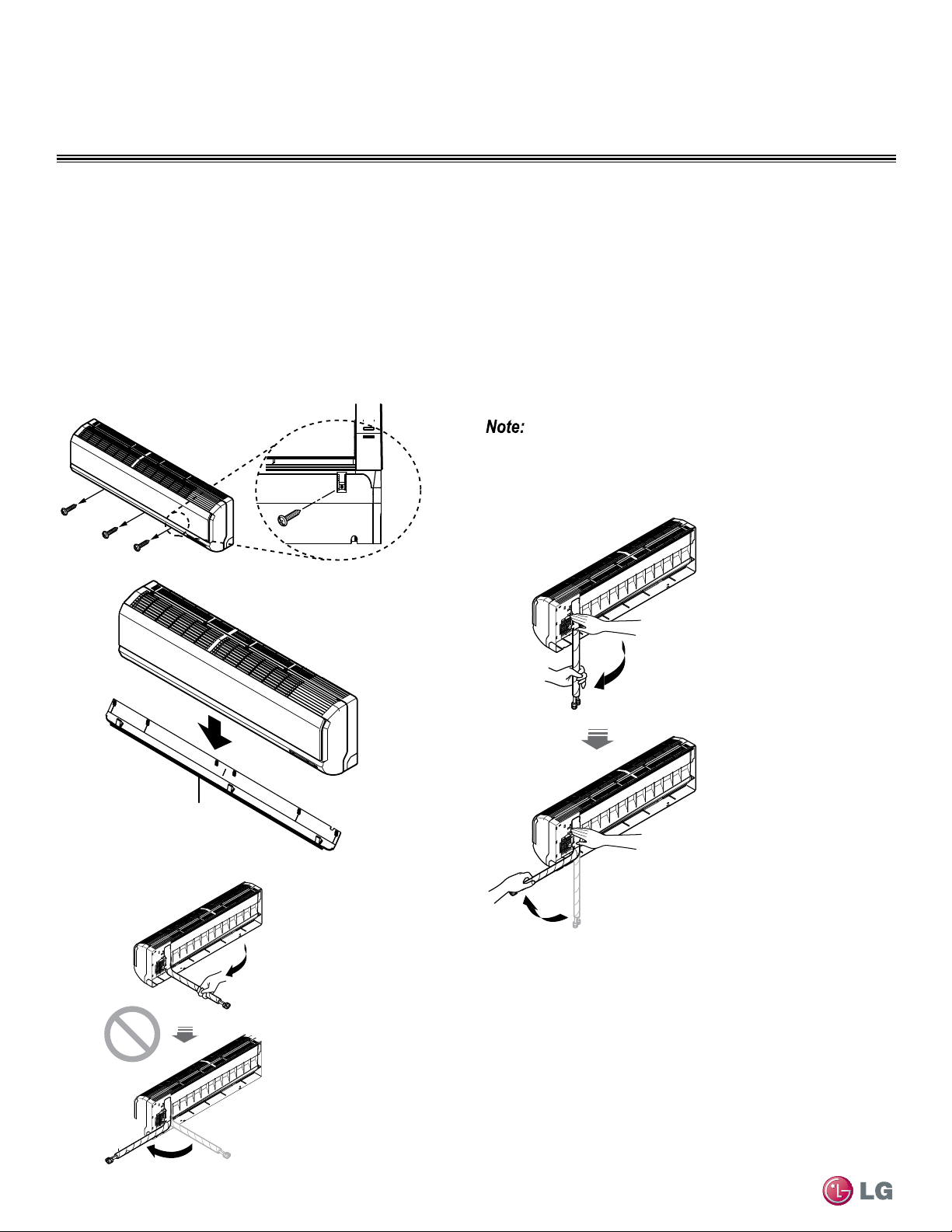
52
Single Zone High Efciency, Standard, Extended Pipe and Mega Wall Mount Installation Manual
Due to our policy of continuous product innovation, some specifications may change without notification.
©LG Electronics U.S.A., Inc., Englewood Cliffs, NJ. All rights reserved. “LG” is a registered trademark of LG Corp.
REFRIGERANT PIPING CONNECTIONS
Indoor Unit Connections
Chassis cover
Follow the steps below and refer to the illustrations on this page to connect piping to the Single Zone indoor unit. To see specific bundling of
piping and drain hose, see Section, “Bundling and Cutting Line” on page 54. Also, refer back to “Drain Hose Guidelines”
section for proper drainage slope during piping procedure.
1. Pull the screw cap at the bottom of the indoor unit (Figure 58).
2. Unscrew the three (3) screws at the bottom of the chassis cover.
3. Remove the chassis cover, being careful not to scratch the main
horizontal vane.
Figure 58: Removing Chassis Cover from Indoor Unit.
4. From the rear of the indoor unit, pull the tubing holder away from
the unit as shown in Figure 59.
5. Remove the pipe port cover.
6. Position the tubing by unfolding the tubing and bending the tubing
slowly downward first, as shown below.
Bending the tubing directly left or right, without bending downward rst,
may cause damage.
Figure 59: Bending Pipe Tubing at Rear of Indoor Unit.
Unfold
slowly
downward
Bend from
downward position
Do not bend tubing
directly backwards
or to the sides
without bending
downward rst!
This may cause
damage!
Piping to Indoor Unit (HSV3, HLV, HXV)
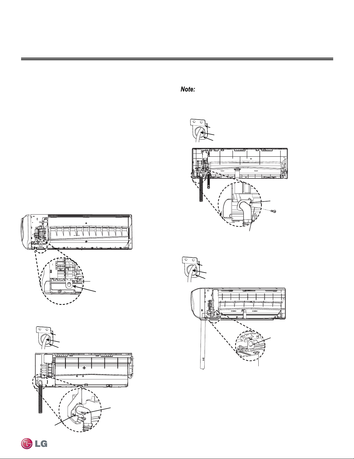
53
Refrigerant Piping Connections
Due to our policy of continuous product innovation, some specifications may change without notification.
©LG Electronics U.S.A., Inc., Englewood Cliffs, NJ. All rights reserved. “LG” is a registered trademark of LG Corp.
REFRIGERANT PIPING CONNECTIONS
1. Follow steps 1 through 6 on the previous page to connect piping
to the rear of the indoor unit.
HV3, HEV and HXV single-zone models require an additional conduit
“bracket/nut” to be installed at the rear of the indoor unit. Follow the
steps below for correct placement for your unit model.
2. Set the conduit by using the bracket and “D” screws from the
accessory kit. This must be done prior to permanent placement
of the piping to the rear of the unit, otherwise you won’t be able
to reach the conduit once piping and drain hose are in place and
anchored.
• For specific bracket placement, see each figure relating to the
specific single-zone model.
Type “D” Screws
HV3 Models
Conduit Bracket
Figure 60: Installing Bracket for Conduit (HV3)
Figure 61: Installing Bracket for Conduit (090HEV)
Figure 62: Installing Bracket for Conduit (120HEV)
Figure 63: Installing Bracket for Conduit (180HEV, 240HEV)
Piping to Indoor Unit - Conduit Bracket Placement (HV3, HEV)
Indoor Unit Connections - Conduit Bracket Placement
Pay attention to bracket placement on each single zone units. Your mod-
el might be slightly different from gure shown in this manual.
For specic bundling (taping) techniques of the Pipe and Drain Hose,
see Section, “Bundling and Cutting Line” on page 54.
090HEV
Conduit
Bracket
Type
“D” Screws
Nut
Bracket
Conduit
Type “D” Screws
Nut
Bracket
Conduit
120HEV
Conduit
Bracket
Type “D” Screws
180HEV, 240HEV
Nut
Bracket
Conduit
Conduit
Bracket
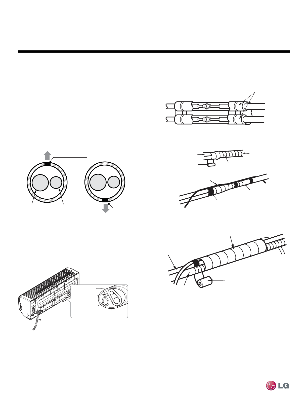
54
Single Zone High Efciency, Standard, Extended Pipe and Mega Wall Mount Installation Manual
Due to our policy of continuous product innovation, some specifications may change without notification.
©LG Electronics U.S.A., Inc., Englewood Cliffs, NJ. All rights reserved. “LG” is a registered trademark of LG Corp.
REFRIGERANT PIPING CONNECTIONS
Bundling and Cutting Line
Piping and cabling must be insulated and bundled together correctly for safety and usage. Follow proper methods and procedures as outlined
here and on the next pages to ensure installation and piping are correctly installed.
Insulation material
As shown in Figure 64, the connection pipe, along with the indoor
unit pipe are fully encased in insulation material.
1. Bind together the two pipes, using vinyl tape. Make sure there
are no gaps during the binding.
2. Be sure the tube cutting line is placed upward (Figure 65).
3. Verify that rear piping house section is wrapped with vinyl tape.
• Use a narrow type of vinyl tape for this step.
4. Continue to wrap the Indoor unit pipe as connected to the outdoor
connection pipe as shown in Figure 66.
Figure 64: Piping with Insulation Material
Figure 65: Correct Cutting Line Placement
Figure 66: Wrapping Connection Pipe to Indoor Unit’s Pipe
Figure 67: Bundling Pipe and Drain Hose, Rear of IDU
Figure 68: Bundling and Placement at Rear of IDU
Gas Pipe
Liquid Pipe
Cutting Line
Cutting Line
Correct Incorrect
Vinyl tape(narrow)
Connection pipe
Connecting cable
Vinyl tape (wide)
Wrap with vinyl tape
Indoor unit pipe
Pipe
Wrap with vinyl tape
Drain hose
Pipe
Vinyl tape(wide)
5. Using a wider vinyl tape, bundle the piping and drain hose togeth-
er (Figure 67).
• Tape should be sufficient to cover the piping in order to fit into the
rear piping housing area at the back of the indoor unit (Figure 68).
Drain hose
Connecting pipe
Connecting
cable
Tape
Drain hose
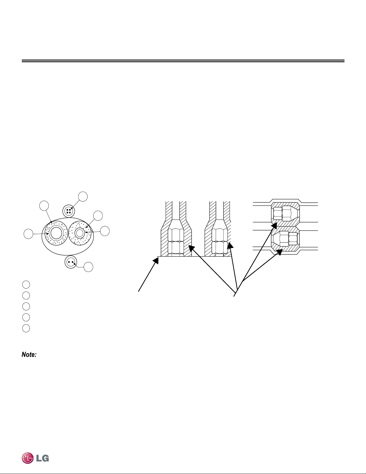
55
Refrigerant Piping Connections
Due to our policy of continuous product innovation, some specifications may change without notification.
©LG Electronics U.S.A., Inc., Englewood Cliffs, NJ. All rights reserved. “LG” is a registered trademark of LG Corp.
REFRIGERANT PIPING CONNECTIONS
Liquid Pipe
Communication Cables
Gas Pipe
Power Wiring
Insulation
A
B
C
D
E
E
D
D
B
A
C
Surface of
Indoor Unit Casing
Field-Provided
Pipe Insulation
Refrigerant Piping Insulation
To prevent heat loss/heat gain through the refrigerant piping, all refrigerant piping including liquid lines and vapor lines must be insulated
separately. Insulation must be a minimum 1/2″ thick, and thickness may need to be increased based on ambient conditions and local codes.
All refrigerant piping including field-provided isolation ball valves, service valves, and elbows must be completely insulated using closed-cell
pipe insulation. All insulation joints must be glued with no air gaps. Insulation material must fit snugly against the refrigeration pipe with
no air space between it and the pipe. Insulation passing through pipe hangers, inside conduit, and/or sleeves must not be compressed.
Protect insulation inside hangers and supports with a second layer. All pipe insulation exposed to direct sunlight and deterioration-produc-
ing elements must be properly protected with a PVC-aluminum vapor barrier jacket, or alternatively placed in a weather-resistant enclosure
such as a pipe rack with a top cover. The design engineer should perform calculations to determine if the factory-supplied insulation jackets
have sufficient thickness to meet local codes and to avoid sweating at jobsite conditions. Maximum refrigerant pipe temperature is 227 °F;
minimum refrigerant pipe temperature is -4 °F. Add additional insulation if necessary.
Figure 69: Typical Pipe Insulation, Power Wire and
Communications Cable Arrangement
Figure 70: Typical Insulation
Butt-Joint at Indoor Unit Casing
Refrigerant Piping Insulation
Figure 71: Typical Refrigerant
Flare Fitting Insulation Detail
• Do not insulate gas and liquid pipes together as
this can result in pipe leakage and malfunction
due to extreme temperature fluctuations.
• Be sure to fully insulate the piping connections.
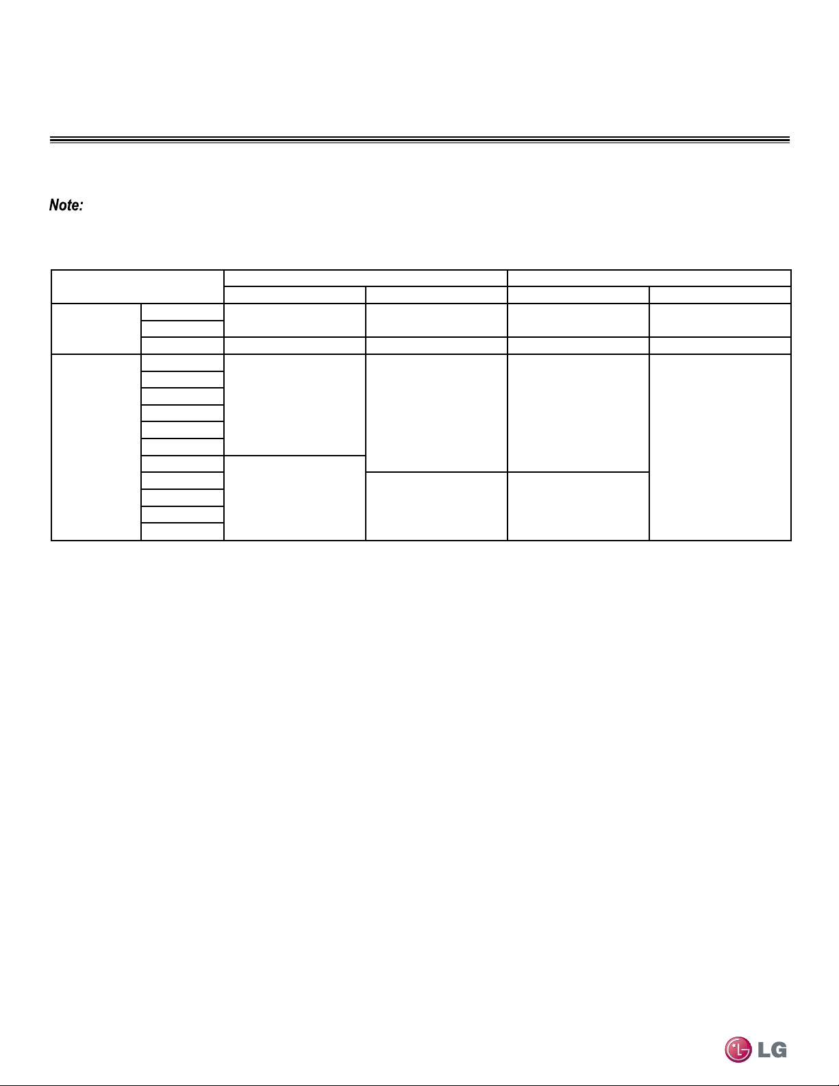
56
Single Zone High Efciency, Standard, Extended Pipe and Mega Wall Mount Installation Manual
Due to our policy of continuous product innovation, some specifications may change without notification.
©LG Electronics U.S.A., Inc., Englewood Cliffs, NJ. All rights reserved. “LG” is a registered trademark of LG Corp.
REFRIGERANT PIPING CONNECTIONS
1. Typical location (Air-conditioned location): When the piping passes through an indoor area where the indoor unit operates.
• Apartment, classroom, office, mall, hospital, etc.
2. Special location (Air-conditioned location):
1. When the location is air conditioned, but there is severe temperature/humidity difference due to high ceilings
• Church, auditorium, theater, lobby, etc.
2. When the location is air conditioned, but internal temperature/humidity are high
• Bathroom, swimming pool, locker room, etc.
3. Typical location (Non-Air conditioned location): When the piping passes through an indoor area where the indoor unit
does not operate.
• Hallway or a dormitory or school, etc.
Minimum Refrigerant Pipe Ethylene Propylene Diene Methylene (EPDM) Insulation Wall Thickness Requirements
4. Special location (Non-Air conditioned location): If conditions 1 and 2 below are present.
1. When the piping passes through an indoor area where the indoor unit does not operate.
2. When the humidity is high and there is no air flow in the location where the piping is installed.
• The thickness of the above insulation material is based on heat conductivity of 0.61 Btu/in/h/ft
2
/°F.
Follow locals codes when selecting EPDM insulation wall thickness.
Classication
Air-conditioned location Non-air conditioned location
1. Typical location 2. Special location 3. Typical location 4. Special location
Liquid pipe
ø1/4 inch
1/2 inch 1/2 inch 1/2 inch 1/2 inch
ø3/8 inch
≥ø1/2 inch 1/2 inch 1/2 inch 1/2 inch 1/2 inch
Vapor pipe
ø3/8 inch
1/2 inch
3/4 inch 3/4 inch
1 inch
ø1/2 inch
ø5/8 inch
ø3/4 inch
ø7/8 inch
ø1 inch
ø1-1/8 inches
3/4 inch
ø1-1/4 inches
1 inch 1 inch
ø1-3/8 inches
ø1-1/2 inches
ø1-3/4 inches
Table 28: Insulation Guidelines for Typical and Special Circumstances
Refrigerant Piping Insulation
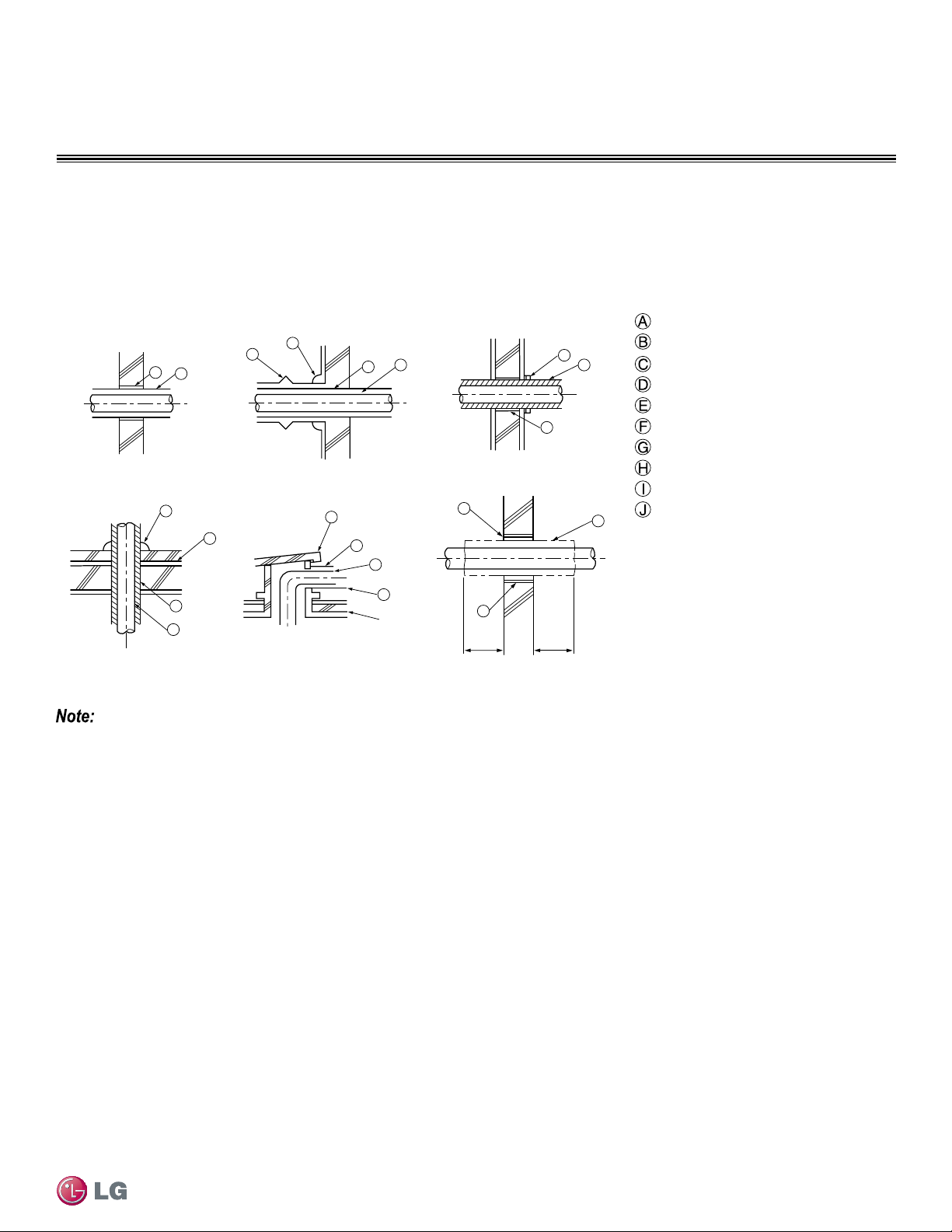
57
Refrigerant Piping Connections
Due to our policy of continuous product innovation, some specifications may change without notification.
©LG Electronics U.S.A., Inc., Englewood Cliffs, NJ. All rights reserved. “LG” is a registered trademark of LG Corp.
REFRIGERANT PIPING CONNECTIONS
Pipe Sleeves at Penetrations
40 in40 in
A
B
D
F
G
B
G
D
B
H
I
J
A
E
B
I
A
B
D
C
Inside wall (concealed)
Floor (fire-resistance)
Area between fire-resistant
insulation and boundary wall
Roof pipe shaft
Outside wall
Outside wall (exposed)
Sleeve
Insulation
Lagging
Caulk
Band
Water-resistant layer
Sleeve with edge
Lagging
Mortar or other fire-resistant caulk
Fire-resistant insulation
When filling an access hole with mortar, cover the
area with steel plate so that the insulation will not
fall through. For this area, use fire-resistant
materials for both the insulation and cover. (Vinyl
cover should not be used.)
Pipe Sleeves at Penetrations
LG requires that all pipe penetrations through walls, floors, and pipes buried underground be properly insulated and routed through an
appropriate wall sleeve of sufficient size to prevent compression of refrigerant pipe insulation and free movement of the pipe within the
sleeve. Underground refrigerant pipe shall be routed inside a protective sleeve to prevent insulation deterioration.
All oor and wall penetrations should be properly sized and large enough to accommodate pipe diameter plus insulation thickness.
Figure 72: Pipe Sleeves at Penetrations
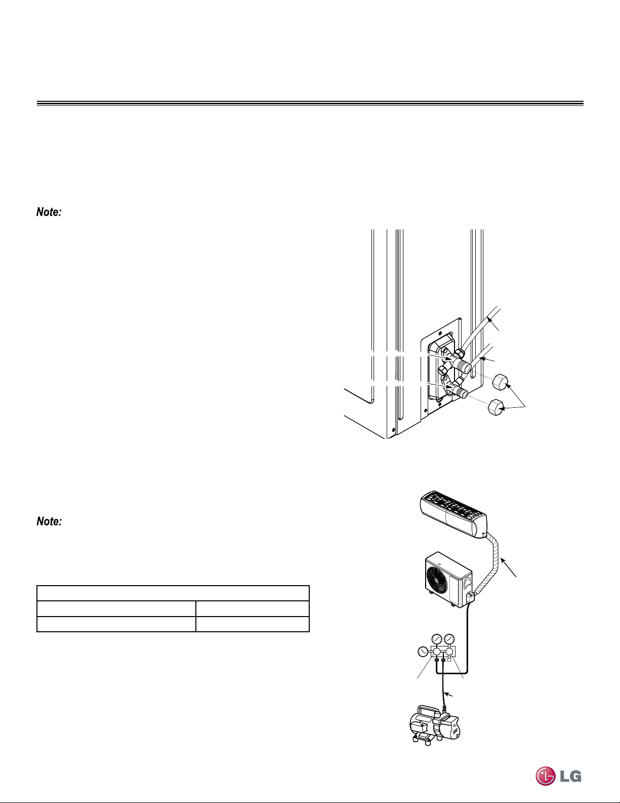
58
Single Zone High Efciency, Standard, Extended Pipe and Mega Wall Mount Installation Manual
Due to our policy of continuous product innovation, some specifications may change without notification.
©LG Electronics U.S.A., Inc., Englewood Cliffs, NJ. All rights reserved. “LG” is a registered trademark of LG Corp.
REFRIGERANT PIPING CONNECTIONS
Air Purging
Air Purging Best Practices
Air purging is done to the piping system after all piping has been connected between the indoor and outdoor unit. This step is necessary to
be sure that air refrigerant can flow through the system without danger of leakage or pressure issues. Air and moisture that is left in the pip-
ing can lead to undesirable results and can cause damage to the working unit. It is important to go through a complete air purging cycle to be
sure that the lines are cleared out. Note that you may have to repeat this process should any air or moisture be found to remain in the piping.
After air purging and evacuating the lines, be sure to take a leak test for all piping and tubing.
Insufficient or incorrectly done air purging may lead to the following:
• Pressure in the system can rise.
• Operating current can rise.
• Cooling or heating efficiency falls.
• Moisture in the refrigerant circuit may freeze and block capillary tubing
• Water can lead to corrosion of parts in the system.
Air Purging with a Vacuum Pump - Preparation Steps
1. Verify that each set of pipes (liquid and gas) are properly con-
nected between the indoor and outdoor unit.
• Verify that all wiring for a test run has been completed.
2. Remove service valve caps from the gas and liquid valves at the
outdoor unit (Figure 73).
• Both the liquid and gas side service valves at the outdoor unit
should be kept closed at this step.
3. Set up the purging, hose connections by referring to Figure 74.
4. Do a Leak Test, by proceeding to Soap Water Method - Leak
Testing section on next page.
• Successful leak testing must be performed before Evacuation can
begin.
5. Go to Evacuation section, on page 60 to complete the purg-
ing process.
Evacuation
Outdoor Unit
Gas side
Liquid side
Valve
Caps
2-way valve(Close)
3-way valve(Close)
2-way valve(Close)
3-way valve(Close)
Figure 73: Removing Service Valve Caps - Outdoor Unit
Figure 74: Evacuation Setup
• Be sure to use a manifold valve for air purging. If it is not available,
use a stop valve for this purpose.
• Be sure that the knob of the three-way valve is always kept close.
Outdoor Unit
Lo Hi
Manifold Valve
Vacuum Pump
Charge Hose
Pressure
Gauge
Lo=Open
Hi=Close
Indoor Unit
Air Purging/ Evacuation Setup
Piping Bundle
Evacuation Table*
Tubing = Less than 33 ft. Tubing = More than 33 ft.
10 minutes or more 15 minutes or more
* Required time for evacuation when 30 gal/h vacuum pump is used.
Table 29: Evacuation Table
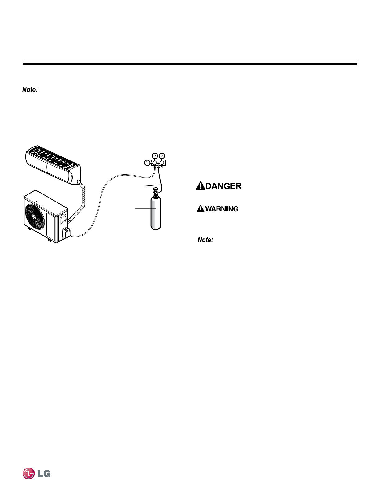
59
Refrigerant Piping Connections
Due to our policy of continuous product innovation, some specifications may change without notification.
©LG Electronics U.S.A., Inc., Englewood Cliffs, NJ. All rights reserved. “LG” is a registered trademark of LG Corp.
REFRIGERANT PIPING CONNECTIONS
Perform the leak test by pressurizing nitrogen gas to 400 psi on both the liquid and gas pipes. Test with the piping service valves closed. If
the pressure does not drop for twenty-four (24) hours, the system passes the test. If the pressure drops, there is a nitrogen leak in the sys-
tem. Find the leak, repair, and then test again.
Leak Test/Soap Method Check
Figure 75: Leak Test Diagram.
Leak Test
Leak Test Ambient Temperature Correction
If the ambient temperature changed between the time when
pressure was applied and when the pressure drop was checked,
adjust results by factoring in approximately 1.45 psi for each 2°F of
temperature difference.
Correction formula = (Ambient temperature when pressure was ap-
plied - Ambient temperature when pressure drop was checked) x 0.01.
Example:
When pressure (550 psig) was applied, the ambient temperature
was 80.6 °F; 24 hours later when pressure drop (540 psi) was
checked, ambient temperature was 68 °F.
Thus, 80.6 - 68 x 0.01 = 0.126. In this case, the pressure drop of
0.126 was due to temperature difference, therefore, there is no leak
in the refrigerant piping system.
Pressure Gauge Hookup
1. Connect the manifold valve (which includes the pressure gaug-
es), along with dry nitrogen gas cylinder to the service valves
using charge hose (Figure 75).
2. Pressurize the system to maximum 150 P.S.I.G. with dry nitrogen
gas and close the cylinder valve when the gauge reading reaches
150 P.S.I.G.
Lo Hi
Outdoor Unit
Manifold Valve
Charge Hose
Nitrogen Gas
Tank (Upright
Position)
Pressure
Gauge
Indoor Unit
Piping Bundle
Leak Test Using Nitrogen Tank
• To avoid nitrogen entering the refrigerant system in a liquid state,
the top of the cylinder must be higher than its bottom when you
pressurize the system.
• Be sure cylinder is used in a vertical standing position.
Soap Water Method - Leak Testing
1. Remove the caps from the 2-way and 3-way valves. See Figure 73.
2. To open the 2-way valve turn the valve stem counter-clockwise
approximately 90°, wait for about 2~3 sec, and close it.
3. While running the nitrogen gas tank hookup, apply a soap water
or a liquid neutral detergent on the indoor unit connection or
outdoor unit connections by using a soft brush.
4. While running the pressure gauge system, observe the connec-
tions for any leakage.
• If you see bubbles appearing at any of the connection points/joints
(at either inside and outside units), it is an indication of leakage.
5. Make a note of where the leaks are coming from along the liquid
and gas piping.
6. Disengage the nitrogen pressure by loosening the charge hose
connector at the Nitrogen cylinder (Figure 75 above).
7. Once system pressure is reduced back to normal range, discon-
nect hose from the cylinder.
8. At this point you will need to make all repairs to connections and
piping where bubbles were observed.
9. Once all repairs are made, repeat soap testing using nitrogen
cylinder and check for any further leaks.
10. Once system is leak free, proceed to Evacuation steps.
Use of combustible gases including oxygen, may result in re or explo-
sion.
Using nitrogen runs the risk of re and explosion. Inert gas (nitrogen)
should be used when checking plumbing leaks, cleaning or repairs of
pipes, etc.

60
Single Zone High Efciency, Standard, Extended Pipe and Mega Wall Mount Installation Manual
Due to our policy of continuous product innovation, some specifications may change without notification.
©LG Electronics U.S.A., Inc., Englewood Cliffs, NJ. All rights reserved. “LG” is a registered trademark of LG Corp.
REFRIGERANT PIPING CONNECTIONS
Finishing the Job
Once the Evacuation procedure has been performed, follow the steps below to turn off all valves at the outdoor unit and safely disengage the
manifold valve, along with the vacuum pump. Refer back to the illustrations and tables on the previous pages as you go through the steps below.
Procedure
1. Using a wrench, turn the valve of the liquid stem counter-clock-
wise to fully open the valve (Figure 73).
2. Turn the valve of the gas stem counter-clockwise to fully open the
valve.
3. Loosen the charge hose connected to the gas side service port
slightly to release the pressure, and then remove the hose.
4. Replace the flare nut and its cap on the gas service port and
fasten the flare nut securely using an adjustable wrench.
• This process is very important to prevent leakage from the system.
5. Replace the valve caps at both gas and liquid side service valves
and then fasten them tightly.
• Once done, this will complete the air purging process with a vacu-
um pump.
Test Running
After leakage testing, and evacuation procedure the system should
be ready to start up for a test run. Follow the guidelines below for
proper procedure.
• Check that all tubing, piping and wiring are properly connected.
• Make sure that the gas and liquid service valves are fully open.
• Start up the system and do a test run.
• As system is up and running verify all is in working order and make
notes as needed to work around any issues that might crop up.
Evacuation
After successful leak testing has been performed, follow Evacuation procedure. Follow the same steps for charge hose hookup to the system.
See Figure 74 on previous page for proper hookup.
Evacuation of Lines
Finishing Up
Procedure
1. Confirm that the “Lo” knob of the manifold valve is open. Refer
back to Figure 74.
2. Confirm that the “Hi” knob of the manifold valve is left closed.
3. Run the Vacuum pump.
• Operate pump until the system has been evacuated down to 300
microns.
• Run pump an additional 15 minutes after reaching micron level.
The duration of the operation of the vacuum pump will vary accord-
ing to pipe length and the capacity of the pump. Refer to Table 29 for
accurate time duration.
4. Turn off the pump and leave the connections secured to the two
service valves.
5. Wait 5 minutes.
6. If the system fails to hold 500 microns or less, check all connec-
tions for tight fit and repeat the evacuation procedure.
7. Once, desired vacuum is reached, close the “Lo” knob of the
manifold valve and stop the vacuum pump.
8. Proceed to Finishing the Job section, below.
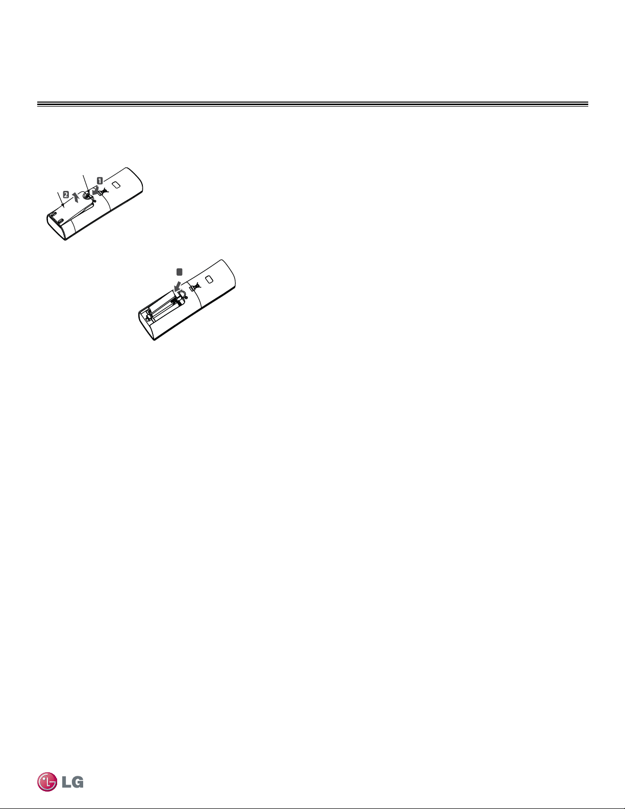
61
Refrigerant Piping Connections
Due to our policy of continuous product innovation, some specifications may change without notification.
©LG Electronics U.S.A., Inc., Englewood Cliffs, NJ. All rights reserved. “LG” is a registered trademark of LG Corp.
REFRIGERANT PIPING CONNECTIONS
Remote Controller
Installing Batteries into Remote
Controller
As part of test running, you will need to insert batteries and power on
the remote controller. To insert the batteries follow the steps below. For
information on using the remote controller, refer to its owner’s manual.
Procedure
1. The remote controller needs two AAA (1.5V) batteries for operation.
Remove the battery cover from the back of the remote controller
(Figure 76).
• Push downward on the tab at the top of the battery cover and then
lift up to remove.
2. Insert the two new batteries.
• Align batteries by the (+) and (-) sides.
• The interior battery compartment of the remote controller will have
clear markings for the (+) and (-) placement.
3. Verify that the batteries have “clicked” into the compartment and
are firmly engaged with the contacts on either side of them.
4. Reattached the back cover of the remote controller.
5. Proceed with powering on the remote controller and usage as
needed.
1. Push down on tab
2. Lift cover
3. Insert 3
batteries
Single Zone Remote Controller - Rear View
Battery Cover
Ta b
Battery
Cover
Figure 76: Remote Controller - Installing Batteries

62
Single Zone High Efciency, Standard, Extended Pipe and Mega Wall Mount Installation Manual
Due to our policy of continuous product innovation, some specifications may change without notification.
©LG Electronics U.S.A., Inc., Englewood Cliffs, NJ. All rights reserved. “LG” is a registered trademark of LG Corp.
REFRIGERANT PIPING CONNECTIONS
Pump Down, Cooling Only Mode
Use a vacuum pump that can evacuate down to 500 microns.
1. If moisture remains in the piping after the system is evacuated for two (2) hours, break the vacuum (down to 7.5 psi with nitrogen gas).
2. Evacuate the system again with the vacuum pump for at least one (1) hour to 500 microns
3. If the system does not reach 500 microns within two (2) hours, repeat the vacuum break and evacuation procedure until the gauge does
not rise.
Pump Down Procedure
This procedure is performed when a unit has to be relocated or the refrigerant circuit is serviced. “Pumping down” is a term used to mean
collecting all refrigerant into the outdoor unit without the loss of any refrigerant. Follow the procedure and guidelines below to safely collect
refrigerant back into the outdoor unit. Always adhere to and be familiar with local codes regarding the handling of refrigerant.
The system must be placed in Cooling mode in order to proceed with the pump down procedure. If needed, refer to the sections on the next
page for proper steps to place the unit into Cooling Mode.
Perform Pump Down procedure only in the cooling mode.
1. Connect a low-pressure gauge with manifold hose to the charge
port on the gas line service valve.
2. Open the gas line service valve halfway.
3. Purge the air in the manifold hose using the refrigerant.
4. Close the liquid line service valve all the way.
5. Turn on the units power switch and start the cooling mode oper-
ation.
6. Observe the pressure gauge reading. When it gets to 1 to 0.5 kg/
cm2G (14.2 to 7.1 P.S.I.G), fully close the gas line valve and then
immediately turn the unit off.
• Pump down procedure is complete at this time and all refrigerant
should be collected into the outdoor unit.
Enabling Cooling Only Mode
Before running the Pump Down procedure, you must place the unit
into Cooling Only Mode. In order to be able to run Cooling Only
Mode, you must enter the unit into the Installer Mode by pressing the
Reset button and the JET MODE button simultaneously.
1. Shut down power to system completely.
2. Enter the Installer Mode as stated in paragraph above.
3. Set code to 45.
4. Press Power-ON button and select the code number 45.
• Unit should beep to acknowledge that code has been received.
5. Turn off power.
• Let unit cycle off for a minimum of 30 seconds.
6. Turn power back on to system.
Disabling Cooling Only Mode
After Pump Down procedure has been performed, you will need
to disable Cooling Only Mode, and place the unit back into normal
operating mode. Follow the procedure below.
1. Shut down power to system completely.
2. Enter the Installer Mode as stated in paragraph above.
3. Set code to 46.
4. Press Power-ON button and select the code number 46.
• Unit should beep to acknowledge that code has been received.
5. Turn off power.
• Let unit cycle off for a minimum of 30 seconds.
6. Turn power back on to system.
• Once the system is in Installer Mode (with Cooling Only Mode initi-
ated), automatic operation is suspended.
• Once Cooling Only Mode is disabled, the unit will return to normal
operation.
• Installer Code cannot be entered if the unit is running. The system
must be completely powered off.
• All Installer Code numbers must be entered into the system during
Power Off state. (Compete shutdown of the system.)
• WLAN Module’s communication time will lag by about 1 minute after
unit is turned back on, and in normal operating mode.
• Entire lock or Mode lock cannot be set if you set heating or automat-
ic operation through the central controller.
Never air purge with refrigerant as it can lead to refrigerant leakage which can cause bodily harm and injury, especially if inhaled.
Never inhale or handle refrigerant directly. Doing so may
cause bodily harm and injury.
63
Electrical Wiring
Due to our policy of continuous product innovation, some specifications may change without notification.
©LG Electronics U.S.A., Inc., Englewood Cliffs, NJ. All rights reserved. “LG” is a registered trademark of LG Corp.
ELECTRICAL WIRING
Capacity of Power Supply Wiring (current) Recommended Minimum Distance
1,2
100V or more
10A 12 inches
50A 20 inches
100A 40 inches
Exceed 100A 60 inches
1
The gures above are based on parallel lengths up to 328 feet long. For lengths in excess of 328 feet, the
distances will have to be recalculated in direct proportion to the additional line lengths involved.
2
If the power supply waveform continues to exhibit some distortion, the space between the power wiring and
communication cable should be increased.
• Position the power wiring a minimum of two (2) inches away from the communication cables to avoid operation problems caused by electri-
cal interference. Do not run both in the same conduit.
• If it is necessary to run the power wiring and communication cable alongside each other and cannot be avoided, see Table 30 below for
minimum recommended distances.
Table 30: Power Wire and Communications Cable Minimum Required Separation Minimum Allowable Distances
• Do not secure the power wiring and communication cables together.
• Do not run the power wiring and the communication cable in the
same conduit. Doing so will result in communication issues due to
electrical noise and motor current leakage.
Separating Power Wires and Communication Cables
• All power wiring and communication cable installa-
tion must be performed by authorized service pro-
viders working in accordance with local, state, and
National Electrical Code regulations related to electrical equipment
and wiring, and following the instructions in this manual.
• Undersized wiring may lead to unacceptable voltage at the unit and
may cause unit malfunction and be a fire hazard.
• Properly ground the Single Zone outdoor and indoor unit. Ground
wiring is required to prevent accidental electrical shock during cur-
rent leakage.
• Ground wiring must always be installed by a qualied technician.
• Do not connect ground wire to refrigerant, gas, or water piping; to
lightning rods; to telephone ground wiring; or to the building plumb-
ing system. Failure to properly provide a National Electrical Code-ap-
proved earth ground can result in equipment malfunction, property
damage, electric shock, physical injury or death.
• Install appropriately sized breakers / fuses / overcurrent protection
switches and wiring in accordance with local, state, and National
Electrical Code regulations related to electrical equipment and wir-
ing, and following the instructions in this manual. Using an oversized
breaker or fuse may result in equipment malfunction, property dam-
age, electric shock, physical injury or death.
• Consider ambient conditions (temperature, direct sunlight, inclement
weather, etc.) when selecting, installing, and connecting the power
wiring.
• Properly ground the Single Zone outdoor and indoor unit. Inproper-
ly ground wire can cause communication problems from electrical
noise, and motor current leakage. Ground wiring must always be in-
stalled by a qualied technician.
• If the system operates in reversed phase, it may damage the com-
pressors and other components.
• If there is a possibility of reversed phase, phase loss, momen-
tary blackout, or the power goes on and off while the system is
operating, install a field-supplied phase loss protection circuit.
General Information and Safety Guidelines
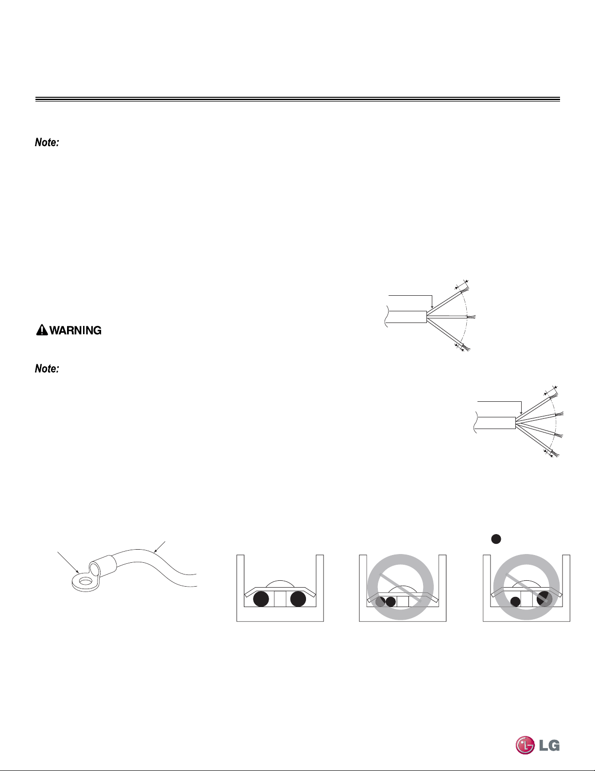
64
Single Zone High Efciency, Standard, Extended Pipe and Mega Wall Mount Installation Manual
Due to our policy of continuous product innovation, some specifications may change without notification.
©LG Electronics U.S.A., Inc., Englewood Cliffs, NJ. All rights reserved. “LG” is a registered trademark of LG Corp.
ELECTRICAL WIRING
Power Supply / Power Wiring Specifications
• Single Zone systems operate at 1Ø, 208-230V, 60Hz, with the exception of Mega 115V, which operates at 1Ø, 115V, 60Hz.
• Power supply, wire type and size should be selected based on National Electrical Code and local codes. Maximum allowable voltage fluctua-
tion ±10% or nameplate rated value. Refer to Figure 77 for wiring guidelines.
• Properly ground the Single Zone outdoor unit and indoor unit per National Electrical Code and local codes.
• Use only copper wiring that is stranded and shielded with the wires separately insulated.
• Ground wire should be longer than the common power/communication wires.
• Refer to the inside of the Chassis Cover for Circuit and Terminal Block Diagrams for your model unit.
• Always match color codes of each wire and follow wiring diagram.
Figure 77: Single Zone Outdoor and Indoor Wiring
and Communications Cable Diagram
:Copper Wire
Terminate multiple power wires of
the same gauge to both sides.
Do not terminate two wires on
one side.
Do not terminate different gauge
wires to a terminal block.
Ring Terminal
Power Wiring
Connecting the Power Wiring Guidelines
Best practice dictates using ring or spade terminals to terminate power wiring at the
power terminal block (Figure 78).
If ring terminals or spade clips are not available, then:
Do not terminate different gauge wires to the power terminal block. Slack in the wiring may
generate heat and re.
• When terminating wires of the same thickness, follow the instructions demonstrated
in the illustrations below at Figure 79.
• Firmly attach the wire; secure in a way to prevent external forces from being impart-
ed on the terminal block.
• Use an appropriately sized screwdriver for tightening the terminals.
• Do not over tighten the connections; overtightening may damage the terminals.
Figure 78: Close up of a Typical Ring Terminal
Figure 79: Proper and Improper Power Wiring Connections
Power Wiring Specications and Best Practices
6/16” ± 2/16”
13/16”
GN/YL
AWG_“A”
Power Wiring, Ground
to Outdoor Unit
Power Wiring, Ground,
Communication Cable
From Outdoor Unit
To Indoor Unit
13/16”
GN/YL
AWG_“B”
Line Voltage
(208/230V)
GN/YL = (Ground, Yellow)
6/16” ± 2/16”
65
Electrical Wiring
Due to our policy of continuous product innovation, some specifications may change without notification.
©LG Electronics U.S.A., Inc., Englewood Cliffs, NJ. All rights reserved. “LG” is a registered trademark of LG Corp.
ELECTRICAL WIRING
• If power wires are not properly terminated and firmly attached, there is risk of fire, electric shock, and physical injury or death.
• Never ground the shield of the communications cable to the indoor unit frame or other grounded entities of the building.
Power Wiring Specications and Best Practices
Power Supply / Power Wiring Specifications - Continued
Communication Cables Between the Single Zone Unit and the Controller
• AC Ez or Simple Central Controller: field-provided, 18 gauge, stranded four-conductor communication cable (shielded).
• All other Central Controllers: field-provided, 18 gauge, stranded two-conductor communication cable (shielded).
• Insulation material as recommended by local code.
• Connect all central control devices such as AC Smart II, AC Smart Premium, ACP, BACnet® and LonWorks® gateways, and energy recovery
ventilators all on the same cable. Order does not matter. Polarity does. Keep “A” terminals with “A” terminals, and “B” terminals with “B” terminals.
• Starting at the outdoor unit, terminate the cable on terminals Internet A and Internet B. Route the cable as needed between each device.
• Use a four (4) conductor, shielded, stranded cable between the
Single Zone outdoor unit and the indoor unit.
• Minimum 18 gauge shielded CVVS or CPEVS cable.
• Insulation material as required by local code.
• Rated for continuous exposure of temperatures up to 140 °F.
• Maximum allowable cable length: 984 feet.
• Firmly attach the cable; provide slack but secure in a way to pre-
vent external forces from being imparted on the terminal block.
• Wiring should be completed without splices.
• Terminate the cable shield to a grounded surface at the outdoor
unit only.
• Always verify the communication cable is connected to a communications terminal on the Single Zone unit. Never apply line
voltage power to the communication cable connection. If contact is made, the PCBs may be damaged.
• The shield of the communications cable connecting the outdoor unit to the indoor unit should be grounded only to the outdoor unit frame.
• Tie the shield of each cable segment together using a wire nut at each indoor unit. Maintain polarity throughout the communication network.
• Position the outdoor unit communications cables away from the power wiring. Refer to minimum spacing requirements provided in
Table 30.
• Never use a common multiple-core communications cable. Each communications bus shall be provided a separate cable (i.e., be-
tween outdoor unit and indoor unit).
General Communication Cable Specifications
• Never apply line voltage power to the communications cable terminal block. If contact is made, the PCBs may be damaged.
• Always include some allowance in the wiring length when terminating. Provide some slack to facilitate removing the electrical
panels while servicing.
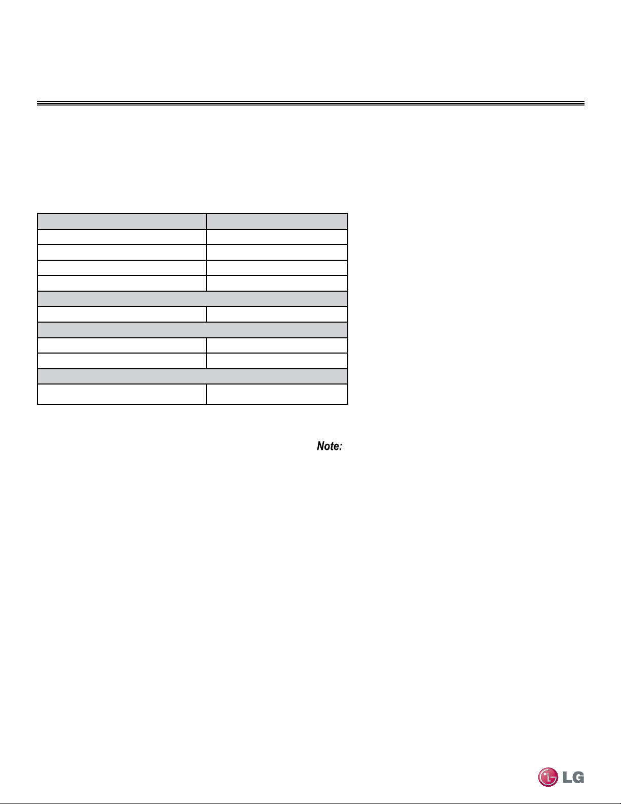
66
Single Zone High Efciency, Standard, Extended Pipe and Mega Wall Mount Installation Manual
Due to our policy of continuous product innovation, some specifications may change without notification.
©LG Electronics U.S.A., Inc., Englewood Cliffs, NJ. All rights reserved. “LG” is a registered trademark of LG Corp.
ELECTRICAL WIRING
Single Zone Model Type Remote Controller Model
LS091HSV3, LS121HSV3 AKB73855712
LS181HSV3 AKB73855712
LS240HSV3 AKB73855713
LS307HV3, LS360HV3 AKB73855713
Single Zone Extended Pipe System
LS240HLV, LS300HLV, LS360HLV AKB74055401
Single Zone Mega System
LS090HEV, LS120HEV AKB73835305
LS180HEV, LS240HEV AKB73835305
Single Zone Mega 115V System
LS090HXV, LS120HXV
AKB73456121
Controllers
Controllers
Refer to Table 31 as to which remote controller models to use for each Single Zone model types. Once all wiring is connected to the indoor
and outdoor units be sure to test the accompanying remote controllers for performance. As always, follow all safety warnings and notes when
operating the Single Zone units using the remote controller.
Table 31: Single Zone Models and Associated Remote Controller Model
Additionally, most of the Single Zone High Efficiency and Extended
Pipe outdoor models can use the following controllers when accom-
panied with the PI 485 VNet Accessory:
• AC Ez
• AC Smart Premium
• ACP
• BACnet®
• LonWorks®
• LGMV
Mega 115V is compatible with the following controllers:
• PREMTB10U
• PQDSB1
• PZCWR5C1
• LS091HSV3, LS121HSV3 models cannot use PI-485, or
the controller accessories.
• Single Zone Mega and Mega 115V systems cannot use PI-
485, or the controller accessories mentioned on this page.
They can use LGMV.
67
Electrical Wiring
Due to our policy of continuous product innovation, some specifications may change without notification.
©LG Electronics U.S.A., Inc., Englewood Cliffs, NJ. All rights reserved. “LG” is a registered trademark of LG Corp.
ELECTRICAL WIRING
Indoor Unit Electrical Connections
Overview - Connecting Indoor Unit Electrical Wiring
The general guidelines for connecting electrical and communication cables to the indoor unit are the same for each of the Single Zone Wall
Mounted indoor units, however, the actual connections on the terminal block will differ. See each illustration for the Single Zone unit model
that you are wiring for correct contact on each terminal block. Depending on your indoor unit, the location of the terminal block on the indoor
unit might vary slightly from the images shown in this section.
• Be sure that main power to the unit is completely off before proceed-
ing with these steps.
• Follow all safety and warning information outlined at the beginning
and throughout this manual. Failure to do so, may cause bodily injury.
Procedure
Be sure there is no power going through the Single Zone system before
proceeding with these connections as there be a risk of electrical shock
and bodily injury.
1. At the bottom panel of the indoor unit, unsnap the latches which
cover the phillips screw heads as shown in Figure 80.
• Normally, there are three (3) screws on the panel, however your
indoor unit model may differ.
2. Using a phillips head screwdriver, remove the screws from the
bottom panel of the indoor unit and set aside (Figure 81).
3. Remove the bottom panel (Figure 82).
• Removal is necessary to gain access to the terminal block which is
situated at the bottom of most indoor units.
• Note that the electrical/communications wiring is usually routed
through the back/bottom of the indoor unit (through a knockout
panel) as shown on the next page (Figure 83).
4. Using a screwdriver, connect the wires as shown on the next
page (Figure 84).
• Each wire should be securely attached to the terminal block.
• Pay attention to the location/connection of the green/yellow ground
cable.
Figure 80: Latch over Screws on Bottom Panel, Indoor Unit
Figure 81: Remove Screws from Bottom Panel
Figure 82: Remove (and Reattachment) Bottom Panel
• Follow all safety and warning information outlined at the beginning
and throughout this manual. Failure to do so, may cause unit failure.
• Some units might require you to remove the Control Cover from the
terminal block area. Most Control Covers are attached with a phillips
screw head.
• Connect the electrical cable to the indoor unit by connecting the
wires to the terminals on the control board individually according to
the outdoor unit connection. Be sure that the color of the wires at the
outdoor unit along with the terminal numbers are the same as those
for the indoor unit.

68
Single Zone High Efciency, Standard, Extended Pipe and Mega Wall Mount Installation Manual
Due to our policy of continuous product innovation, some specifications may change without notification.
©LG Electronics U.S.A., Inc., Englewood Cliffs, NJ. All rights reserved. “LG” is a registered trademark of LG Corp.
ELECTRICAL WIRING
Figure 83: Indoor Unit Knockout (Communication Wires)
Figure 84: Indoor Unit Terminal Block with Grounding Cable
(Example Only)
Indoor Unit Electrical Connections
Connecting Indoor Unit Electrical Wiring - Continued
5. When done, reattach the bottom panel to the indoor unit, being
careful to align panel using the rear tabs.
• You might need to give the panel a gentle tap with the palm of your
hand to be sure it engages at the bottom.
6. Using a phillips screwdriver, reattach the screws to the bottom
panel and secure.
7. Once screws are in place, re-snap the latches over the screws.
• Refer back to Figure 80 as an example.
8. If all other piping and electrical wiring to the outside unit has been
completed at this stage, you can turn the system on to test.
• If you have not completed the piping connections, do not turn pow-
er on at this time and proceed to complete all other piping, (along
with drain hose) and wiring to the system.
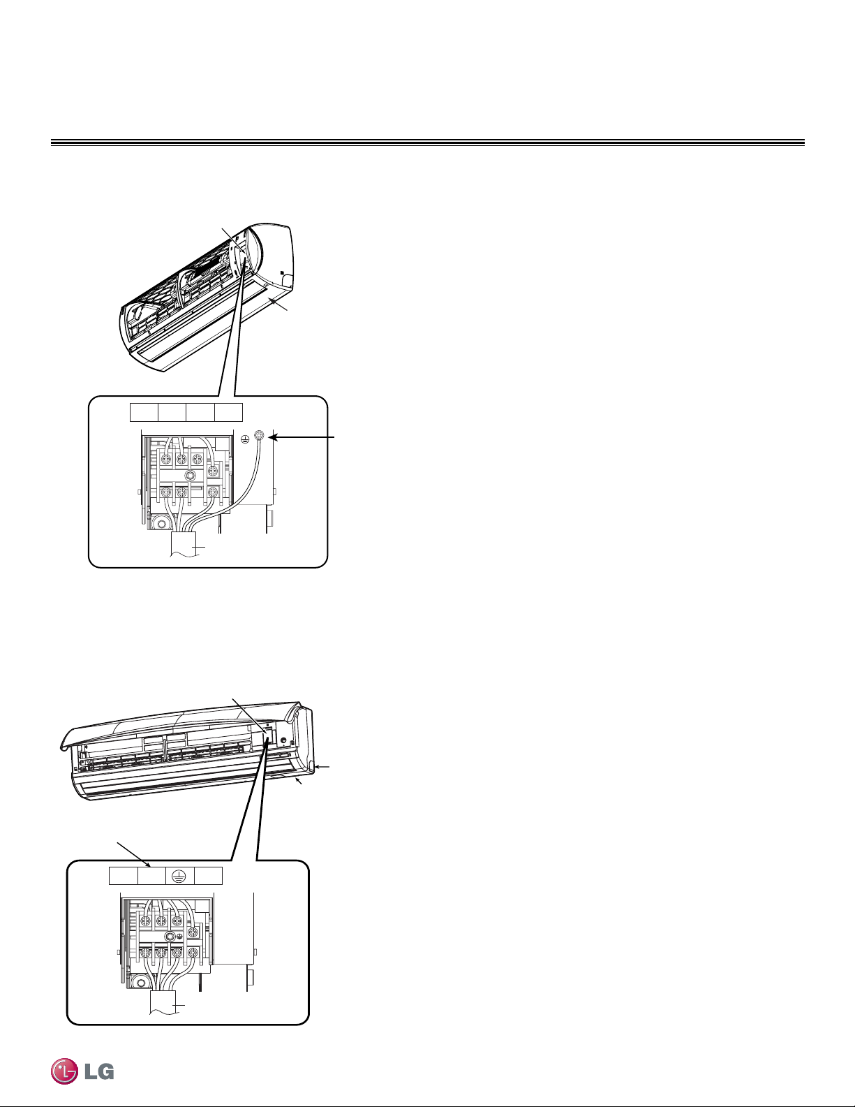
69
Electrical Wiring
Due to our policy of continuous product innovation, some specifications may change without notification.
©LG Electronics U.S.A., Inc., Englewood Cliffs, NJ. All rights reserved. “LG” is a registered trademark of LG Corp.
ELECTRICAL WIRING
Control Cover
Bottom Panel
Electrical Wiring
Knockout
Indoor Unit
HLV
1(L1)
2(L2)
3
1(L )2(N )
3
Power Connection Cable
Grounding Cable
Figure 85: HLV Indoor Units - Terminal Block Connections
Figure 86: HV3 and 240HSV3 Indoor Units - Terminal Block Connections
Indoor Unit Electrical Connections
Terminal Block Connection for HLV
See Figure 85 for specific terminal block wiring for all following
Single Zone models:
LSN240HLV
LSN300HLV
LSN360HLV
Terminal Block Connection for HV3
See Figure 86 for specific terminal block wiring for all following
Single Zone models:
LSN307HV3
LSN360HV3
Terminal Block Connection for
240HSV3
See Figure 86 for 240HSV3 Single Zone terminal block connection.
The connections are also identical for LSN307HV3 and LSN360HV3
Single Zone models.
1(L1) 2(L2) 3
1(L1) 2(L2 )
3
Power Connection Cable
Control Cover
307HV3, 360HV3
240HSV3
Knockout Cover
Bottom Panel
Terminal Block Connections
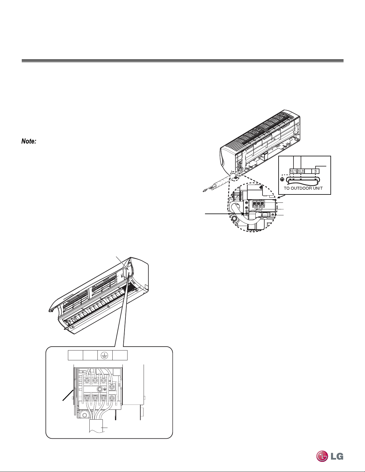
70
Single Zone High Efciency, Standard, Extended Pipe and Mega Wall Mount Installation Manual
Due to our policy of continuous product innovation, some specifications may change without notification.
©LG Electronics U.S.A., Inc., Englewood Cliffs, NJ. All rights reserved. “LG” is a registered trademark of LG Corp.
ELECTRICAL WIRING
Terminal Block Connection for
091HSV3, 121HSV3, 181HSV3
See Figure 87 for specific terminal block wiring for all following
Single Zone models:
LSN091HSV3
LSN121HSV3
LSN181HSV3
Terminal Block
Terminal Block
Expanded View
Grounding
Cable
Connecting Cables
Cable Restrainer
091HSV3,121HSV3
181HSV3
Indoor Unit Electrical Connections
Figure 87: 091HSV3, 121HSV3, 181HSV3 Indoor Units - Terminal
Block Connections
Figure 88: Mega 090HEV, 120HEV, 180HEV, 240HEV Indoor Units
- Terminal Block Connections
• Pay special attention to the location of the grounding cable and the
cable restrainer around the other electrical/communication cables
when connecting.
• Note that the terminal block is located behind the drain hose and
bundled piping on these units.
Terminal Block Connection for Mega
090HEV, 120HEV, 180HEV, 240HEV
See Figure 88 for specific terminal block wiring for all following
Single Zone models:
LSN090HEV
LSN120HEV
LSN180HEV
LSN240HEV
Control Cover
1(L1) 2(L2) 3
1(L1) 2(L2)
3
Power connecting cable
Terminal
Block
090HEV, 120HEV
180HEV, 240HEV
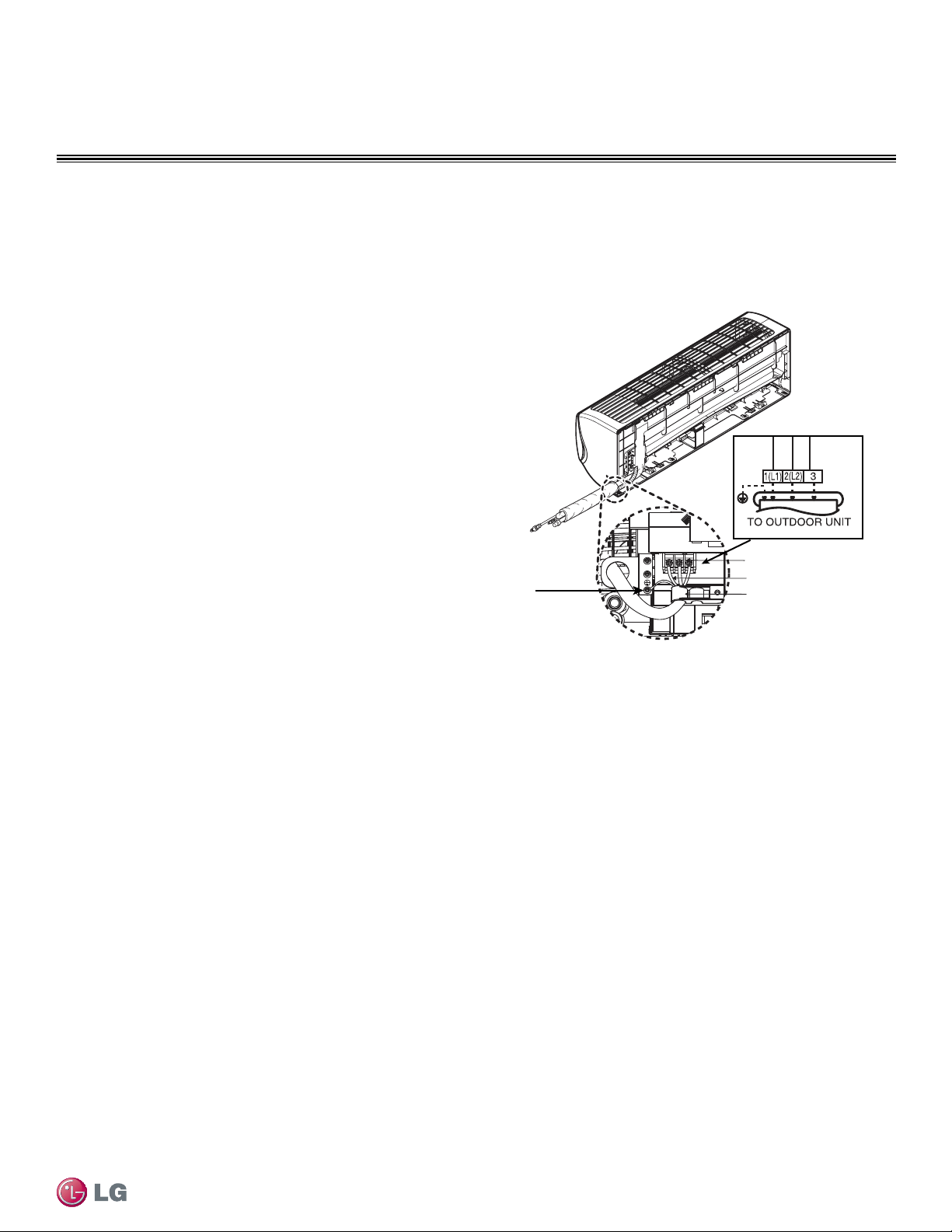
71
Electrical Wiring
Due to our policy of continuous product innovation, some specifications may change without notification.
©LG Electronics U.S.A., Inc., Englewood Cliffs, NJ. All rights reserved. “LG” is a registered trademark of LG Corp.
ELECTRICAL WIRING
Terminal Block Connection for Mega 115V
090HXV, 120HXV
See Figure 88XX for specific terminal block wiring for all following Single
Zone models:
LSN090HXV
LSN120HXV
Indoor Unit Electrical Connections
Terminal Block
Terminal Block
Expanded View
Grounding
Cable
Connecting Cables
Cable Restrainer
090HXV, 120HXV
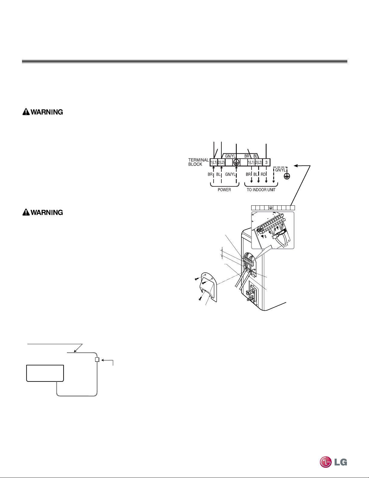
72
Single Zone High Efciency, Standard, Extended Pipe and Mega Wall Mount Installation Manual
Due to our policy of continuous product innovation, some specifications may change without notification.
©LG Electronics U.S.A., Inc., Englewood Cliffs, NJ. All rights reserved. “LG” is a registered trademark of LG Corp.
ELECTRICAL WIRING
Outdoor Unit Electrical Connections
HLV
Electrical Connections
Outdoor Unit
Terminal Block
Over 0.2”
Conduit Panel
Conduit Panel Cover
Connection/Communication
Cable (Leading to Indoor Unit)
Power Cord
1(L1) 2(L2) 1(L1) 2(L2)
3
HLV
Connecting Outdoor Unit Electrical Wiring
The general guidelines for connecting electrical and communication cables to the outdoor unit are the same for each of the Single Zone Wall
Mount units, however, the actual connections on the terminal block will differ. See each illustration for the Single Zone unit model that you are
installing for correct wiring of each terminal block.
• Be sure that main power to the unit is completely off before pro-
ceeding with these steps. Follow all safety and warning information
outlined at the beginning of this manual. Failure to do so, may cause
bodily injury.
• Be sure that a circuit breaker or some other emergency power cutoff
device is in place before any power wiring is done to the system.
Failure to do so, may cause bodily injury or death.
• Never touch any power lines or live cables before all power is cutoff
to the system. To do so, may cause bodily injury or death.
Air
Conditioner
Main Power Source
Circuit Breaker
Use a circuit breaker
or time delay fuse
Figure 89: Circuit Breaker
Figure 90: HLV Outdoor Unit - Electrical Connections
Procedure
Refer to Figure 89 below, for an example of how a circuit breaker
should be wired through to the Single Zone system.
• Be sure there is no power going through the Single Zone system
before proceeding with these connections as it may result in electric
shock.
• Familiarize yourself with the location of the circuit breaker and be
sure that all power is cut to the Single Zone unit as it may result in
electric shock.
1. Using a phillips head screwdriver, remove the conduit panel cover
from the outside unit.
2. Before proceeding, inspect all wiring inside the casing to be sure
they are secure and have not come loose during transportation
and installation of the outdoor unit.
• Loose wires can cause the wiring to burn out quickly.
• Inspect wires for any damage or cracks (manufacturing defects).
3. Confirm that electrical power supply capacity is sufficient to run
the unit. See specifications sheets at the beginning of this instal-
lation manual for details on power.
4. Confirm that you are using the right gauge size for wiring to
proceed.
5. Using a screwdriver, connect the wires as shown in Figure 90.
• Figure 90 shows the connections for the HLV models, however the
basic connection procedure is the same for all models. Use this
diagram as a general reference on connecting the power cables.
• Each wire should be securely attached to the terminal block.
• Bundle the cabling by using a cable restrainer.
• Pay attention to the location/connection of the green/yellow
grounding cable; as in some models the connection may be located
to the side of the actual terminal block.
• Maintain a minimum of .2” of wire length from terminal block to
cable bundle.
Terminal Block Connection for HLV
See Figure 90 for specific terminal block wiring for all following
Single Zone outdoor unit models:
LSN240HLV
LSN300HLV
LSN360HLV
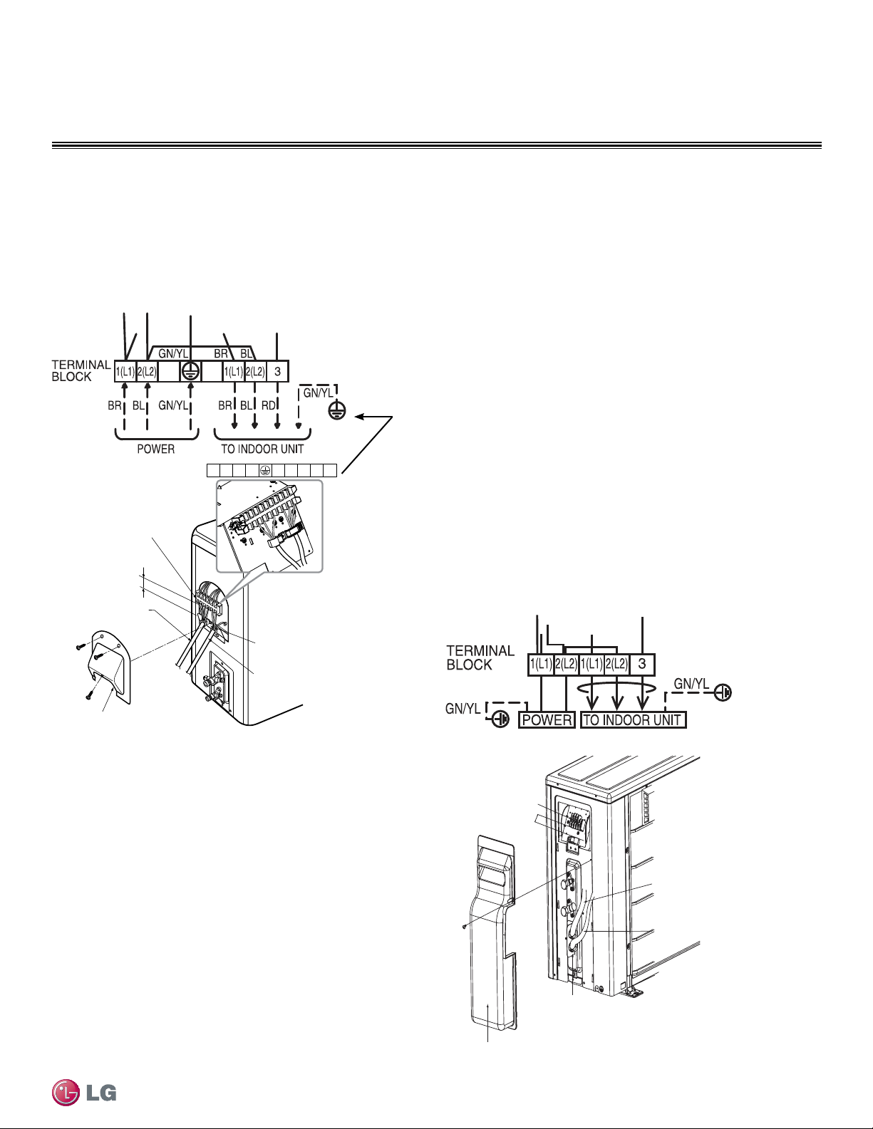
73
Electrical Wiring
Due to our policy of continuous product innovation, some specifications may change without notification.
©LG Electronics U.S.A., Inc., Englewood Cliffs, NJ. All rights reserved. “LG” is a registered trademark of LG Corp.
ELECTRICAL WIRING
Terminal Block Connection for
091HSV3, 121HSV3
See Figure 92 for specific terminal block wiring for all following
Single Zone outdoor unit models:
LSU091HSV3
LSU121HSV3
Outdoor Unit Electrical Connections
Terminal Block Connection for HV3
See Figure 91 for specific terminal block wiring for all following
Single Zone outdoor unit models:
LSU307HV3
LSU360HV3
Connecting Outdoor Unit Electrical Wiring - Continued
HV3 (All models)
181HSV3, 240HSV3
Electrical Connections
Outdoor Unit
Terminal Block
Over 0.2”
Conduit Panel
Connection/Communication
Cable (Leading to Indoor Unit)
Power Cord
Conduit Panel Cover
1(L1) 2(L2) 1(L1) 2(L2 )
3
HV3
181HSV3, 240HSV3
Figure 91: HV3 and 181HSV3, 240HSV3 Outdoor Unit - Electrical
Connections
Figure 92: 091HSV3, 121HSV3 Outdoor Unit - Electrical Connections
Terminal Block Connections for
181HSV3 and 240HSV3
See Figure 91 for 181HSV3 and 240HSV3 Single Zone terminal
block connections. The connections are identical to the HV3
outdoor units.
091HSV3, 121HSV3
Terminal Block
Connection/Communication
Cable (Leading to Indoor Unit)
Power Cord
Conduit Panel
Tubing Cover
Over
0.2"
091HSV3, 121HSV3
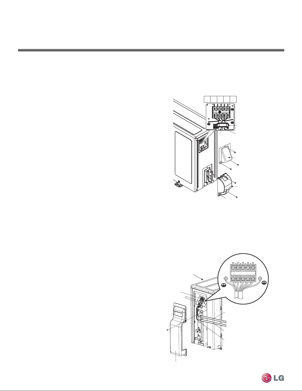
74
Single Zone High Efciency, Standard, Extended Pipe and Mega Wall Mount Installation Manual
Due to our policy of continuous product innovation, some specifications may change without notification.
©LG Electronics U.S.A., Inc., Englewood Cliffs, NJ. All rights reserved. “LG” is a registered trademark of LG Corp.
ELECTRICAL WIRING
Outdoor Unit Electrical Connections
Terminal Block Connection for
090HEV, 120HEV
See Figure 93 for specific terminal block wiring for all following
Single Zone outdoor unit models:
LSU090HEV
LSU120HEV
Conduit panel
cover
Tu bing cover
Terminal block
Outdoor Unit
090HEV, 120HEV
1(L1) 2(L2)1(L1) 2(L2)
3
Power
connecting
cable
Power
cord
Cord clamp
Figure 93: 090HEV, 120HEV Outdoor Unit - Electrical Connections
Figure 94: 180HEV Outdoor Unit - Electrical Connections
Terminal Block Connection for
180HEV
See Figure 94 for specific terminal block wiring for all following
Single Zone outdoor unit models:
LSU180HEV
Terminal block
Conduit panel
Outdoor unit
Tubing cover
Over 0.2"
Power supply cord
Connecting cable
1(L1) 2(L2) 1(L1) 2(L2) 3
180HEV
Connecting Outdoor Unit Electrical Wiring - Continued
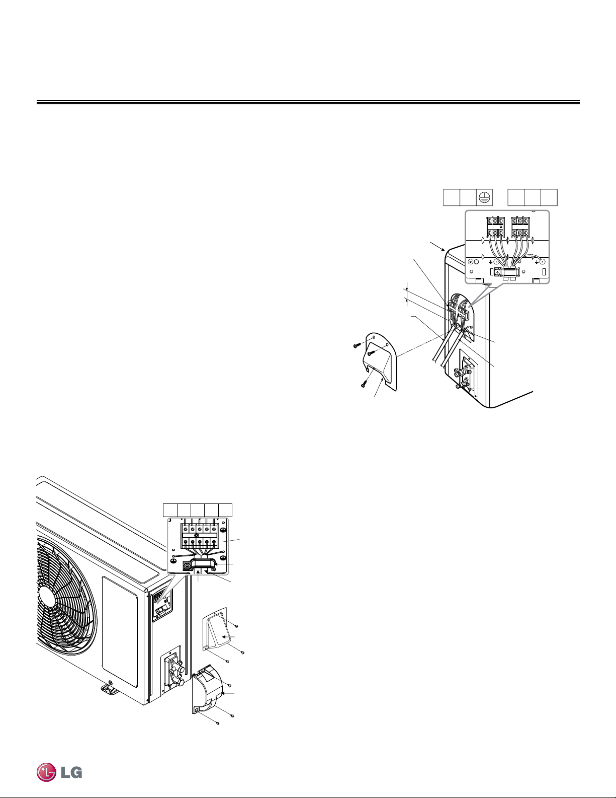
75
Electrical Wiring
Due to our policy of continuous product innovation, some specifications may change without notification.
©LG Electronics U.S.A., Inc., Englewood Cliffs, NJ. All rights reserved. “LG” is a registered trademark of LG Corp.
ELECTRICAL WIRING
Outdoor Unit Electrical Connections
Terminal Block Connection for HXV
See Figure 96 for specific terminal block wiring for all following
Single Zone outdoor unit models:
LSN090HXV
LSN120HXV
Figure 95: 240HEV Outdoor Unit - Electrical Connections
Figure 96: 090HXV, 120HXV Outdoor Unit - Electrical Connections
Terminal Block Connection for
240HEV
See Figure 95 for specific terminal block wiring for the following
Single Zone outdoor unit model:
LSU240HEV
Outdoor unit
Terminal block
Conduit Panel Cover
Over 0.2”
Conduit panel
Connecting
cable
Power supply
cord
1(L1)
2(L2)
3
1(L1)
2(L2)
1(L) 2(N)
3L N
1(L1)2(L2)
3
1(L1)2(L2)
240HEV
Tubing cover
Terminal Block
L
N
1(L)
2(N) 3
Power
connecting
cable
Power
cord
Cord clamp
Conduit panel
cover
090HXV, 120HXV
Connecting Outdoor Unit Electrical Wiring - Continued
76
Single Zone High Efciency, Standard, Extended Pipe and Mega Wall Mount Installation Manual
Due to our policy of continuous product innovation, some specifications may change without notification.
©LG Electronics U.S.A., Inc., Englewood Cliffs, NJ. All rights reserved. “LG” is a registered trademark of LG Corp.
ELECTRICAL WIRING
Additional screens can be accessed by tabs on the main screen.
Additional screens include the following:
1. Cycleview (Figure 98): Graphic of internal components including:
• Compressors showing actual speeds
• EEVs
• IDUs
• Temperature and pressure sensors
• Four-way reversing valve
2. Graph: Full screen graph of actual high and low pressures and high
and low pressure limits. A sliding bar enables user to go back in
time and view data.
3. Control FTN: Enables user to turn on IDUs in 1.8 °F increments.
4. Useful Tab
• Unit Conversion: Converts metric values to imperial values.
• Actual inverter compressor speed
• Target inverter compressor speed
• Actual outdoor fan speed
• Target outdoor unit fan speed
• Actual superheat
• Target superheat
• Actual subcooler circuit superheat
• Target subcooler circuit superheat
• Main EEV position
• Subcooling EEV position
• Inverter compressor current transducer value
• Outdoor air temperature
• Actual high pressure/saturation temperature
• Actual low pressure/saturation temperature
• Suction temperature
• Inverter compressor discharge temperature
• Front outdoor coil pipe temperature
• Back outdoor coil pipe temperature
• Liquid line pipe temperature
• Subcooler inlet temperature
• Subcooler outlet temperature
• Average indoor unit (IDU) pipe temperature
• Inverter compressor operation indicator light
• Liquid injection
valves’ operation
indicator lights
• Hot gas bypass valve
operation indicator
light
• Four-way reversing
valve operation
indicator light
• Pressure graph
showing actual low
pressure and high
pressure levels
• Error code display
• Operating mode
indicator
• Target high pressure
• Target low pressure
• PCB (printed circuit board) version
• Software version
• Installer name
• Model number of IDUs
• Site name
• Total number of connected IDUs
• Communication indicators
• IDU capacity
• IDU operating mode
• IDU fan speed
• IDU EEV position
• IDU room temperature
• IDU inlet pipe temperature
• IDU outlet pipe temperature
• IDU error code
LG Monitoring View (LGMV) Diagnostic Software
LGMV software (PRCTSL1 and PRCTFE1) allows the service technician or commissioning agent to connect a computer USB port to the
Single Zone unit’s main printed circuit board (PCB) using an accessory cable without the need for a separate interface device. The monitor-
ing screen for LGMV allows the user to view the following real time data on one screen (Figure 97):
Figure 97: MV Real-time Data Screen
Figure 98: MV Cycleview
Images on these pages are examples of LGMV screenshots. Actual images may differ depending on the version of the software and the unit installed.
Self Diagnosis Functions

77
Electrical Wiring
Due to our policy of continuous product innovation, some specifications may change without notification.
©LG Electronics U.S.A., Inc., Englewood Cliffs, NJ. All rights reserved. “LG” is a registered trademark of LG Corp.
ELECTRICAL WIRING
Self Diagnosis Functions
5. Data (Figure 99)
• Data Saving Start: Recording of real time data to a separate file created to be
stored on the user’s computer.
• Data Loading Start: Recorded data from a saved “.CSV” file can be loaded to
create an LGMV session.
6. Monitoring
• Electrical: The lower half of main screen is changed to show Inverter
Compressor Amps, Volts, Power Hz, Inverter control board fan Hz.
Figure 99: MV Control Indoor Units Screen
The software is available in a high version with all of the features listed above. The low version has all features as the high version without
Target High Pressure and Target Low Pressure values shown on main screen.
In lieu of connecting to the Water Source Unit (WSU), user has the option to connect to IDU with the use of a USB to RS-485 connector kit.
When connected through IDU, user will not be able to record data.
This software can be used to both commission new systems and troubleshoot existing systems. LGMV data can be recorded to a “.CSV” file
and emailed to an LG representative to assist with diagnostic evaluations.
Recommended Minimum PC Configuration:
Error Codes
LGMV software helps the service technician or commissioning agent
to troubleshoot system operation issues by displaying malfunction
codes (Figure 100). These error codes can be seen on the main
screen of the LGMV software program. For an overview of Single
Zone unit error codes, see Error Codes section. For detailed infor-
mation on how to troubleshoot individual error codes, see the Single
Zone Service Manual.
Figure 100: Error Code Screen
Images on these pages are examples of LGMV screenshots. Actual images may differ depending on the version of the software and the units installed.
• CPU: Pentium
®
IV 1.6 GHz
• Main Memory: 1G
• Operating System: Windows
®
XP/Vista/7 32 bit (recommended),
64 bit
• Hard Disk: 600 MB when operating
• MS Office 2003, 2007 (recommended) for select reporting
functions
LG Monitoring View (LGMV) Diagnostic Software and Cable - Continued
78
Single Zone High Efciency, Standard, Extended Pipe and Mega Wall Mount Installation Manual
Due to our policy of continuous product innovation, some specifications may change without notification.
©LG Electronics U.S.A., Inc., Englewood Cliffs, NJ. All rights reserved. “LG” is a registered trademark of LG Corp.
ELECTRICAL WIRING
LG SIMS - Self Diagnosis Functions
LG SIMs
WLAN Module
LG SIMs App
on Smart Phone
The SIMs WLAN module and the smart phone app together provide monitoring and troubleshooting capability for
LG Duct Free Systems. SIMs functions only with LG Duct Free products (Figure 101).
SIMs can display and graph operational data for the air conditioner system including the indoor unit and
the outdoor unit. SIMs also displays error codes and a troubleshooting guide. A full copy of the LG SIMs
Smart Inverter Monitoring System User’s Manual is available on the www.lghvac.com website.
To use SIMs you must be a trained HVAC service technician familiar with variable refrigerant flow
(VRF) systems in general and with LG’s Duct Free System products. You should understand the
inverter air conditioning operation cycle, the meaning of the data displayed by SIMs, and how to use the
data to troubleshoot the system.
Figure 102 shows a Multi F configuration used with the SIMs module and app. LG SIMs can also be used
with Single Zone one-to-one configurations such as the Single Zone Wall Mount systems.
• The Duct Free System air conditioning system
must run for at least 15–20 minutes before data
collected by SIMs 2.0 is valid for troubleshooting.
• You must have the free SIMs app correctly in-
stalled on your smart phone before using SIMs.
• Some ODUs have an LGMV extension cable ac-
cessed by removing the side handle cover. If the
ODU does not have this extension cable, access
the LGMV connector by removing the top cover
of the ODU.
High voltages capable of causing death are used in this equipment. Out-
door unit power remains connected during this procedure. Take extreme
caution not to touch electrical components or connections. Failure to
observe this warning can result in death or severe injury.
Figure 101: LG SIMs App and WLAN Module
Figure 102: SIMs WLAN Module to Typical DFS System
Figure 103: SIMs App Main Info Screen
The main screen is the first screen displayed after wireless connection is
established. Tap the Main Info tab to display current readings regarding
your indoor and outdoor unit(s). The Operational Info area of the screen
will show active functions or modes by illuminating the light to the right of
the function (Figure 103).
Additional Help information can be accessed by tapping the Help Menu
buttons at the bottom of this screen.
Operational
Information
AC Cycle
Information on
Main Info Tab
Help Menu
(File is Factory Use Only)
SIMs App Main Info Screen
79
Electrical Wiring
Due to our policy of continuous product innovation, some specifications may change without notification.
©LG Electronics U.S.A., Inc., Englewood Cliffs, NJ. All rights reserved. “LG” is a registered trademark of LG Corp.
ELECTRICAL WIRING
LG SIMS - Self Diagnosis Functions
SIMs App Screens
Outdoor Info/
Component Screen
Displays the following
information:
• Frequency
• FAN1 RPM
• FAN2 RPM
• DC Link
• Current
• Voltage
• EEV Mode
• Restart Timer
• Comp Mode
• EEV
Indoor Info Tab
Displays the following
information:
• Frequency
• Operation
• THM Mode
• REM Mode
• FAN
• EEV
• Air Temp
• Pipe-in
• Pipe-mid
• Pipe-out
Graph Info Tab
This tab, has three
sub sections:
• IDU - Indoor Unit
Temperature graph.
Displays IDU
information in graph
format. Information
displayed is for the
IDU # selected on
the Main screen.
• ODU - Outdoor Unit
Temperature and
Frequency graph.
Displays ODU
information in graph
format.
• ODU Electric -
Outdoor Unit Electric
data graph is
displayed.
Outdoor Info/
Temperature Screen
Displays the following
information:
• Inv TD
• Suction
• Discharge
• Cond Mid
• Cond Out
• Heatsink
• Air Temp
80
Single Zone High Efciency, Standard, Extended Pipe and Mega Wall Mount Installation Manual
Due to our policy of continuous product innovation, some specifications may change without notification.
©LG Electronics U.S.A., Inc., Englewood Cliffs, NJ. All rights reserved. “LG” is a registered trademark of LG Corp.
TROUBLESHOOTING
Troubleshooting Using Error Codes
Refer to Table 32 and Table 33 for error codes that are generat-
ed from the indoor and outdoor units. These codes are the most
common that will manifest through these units. Your particular model
duct free system might generate additional codes not listed here.
Please contact LG Support if you see these types of errors and a
simple power down and boot up has not corrected the issue. You
should not attempt to fix the system yourself.
Error Codes
• Refer to the figures below for your particular indoor unit’s LED
configuration.
• Indicate different types of unit failures, assists in self-diagnosis and
to track the frequency of occurrence.
Error Codes
• Error codes are shown on the LEDs of indoor units, wired remote
controller, the Single Zone unit control board, and LG Monitoring
View (LGMV) Diagnostic Software.
• If two or more errors occur simultaneously, the lower error code
number is displayed rst.
• After error is resolved, the error code does not display.
Decoding the Error Display
The first and second number on the LED indicates error number.
Example: 21 = LED1 (Green light) 2x blink, LED2 (Red light) 1x blink
Error Code Nomenclature Definitions
• MICOM: Non-volatile memory chip where unit setup information is
stored.
• EPROM: Non-volatile memory chip where device identification,
size, and factory defined default component operating parameters
are stored.
Receiver
LED 1
(UNITS PLACE)
LED 2
(TENS PLACE)
LED 1
(UNITS PLACE)
LED 2
(TENS PLACE)
Receiver
Figure 104: IDU LS-HSV3 Models
Figure 105: IDU Some HSV Models
Figure 106: IDU LS-HV3/Some HSV Models
LED 2
(TENS PLACE)
Receiver
LED 1
(UNITS PLACE)
Error
Code
Description
No. of Times Indoor Unit
LEDs Blink
LED1
(Plasma LED)
LED2
(Power LED)
1 Indoor unit room temperature sensor error
1X -
2 Indoor unit inlet pipe sensor error 2X -
4 Float switch error (optional) 4X -
5 Communication error between indoor unit and outdoor units - 5X
6 Indoor unit outlet pipe sensor error 6X -
9 Indoor unit EEPROM error 9X -
10 Indoor unit BLDC motor fan lock - 1X
12 Indoor unit middle pipe sensor error 2X 1X
Table 32: Single Zone Wall Mounted Indoor Unit Error Codes
LED 1
(UNITS PLACE)
LED 2
(TENS PLACE)
Receiver
Figure 107: IDU LS-HEV Models
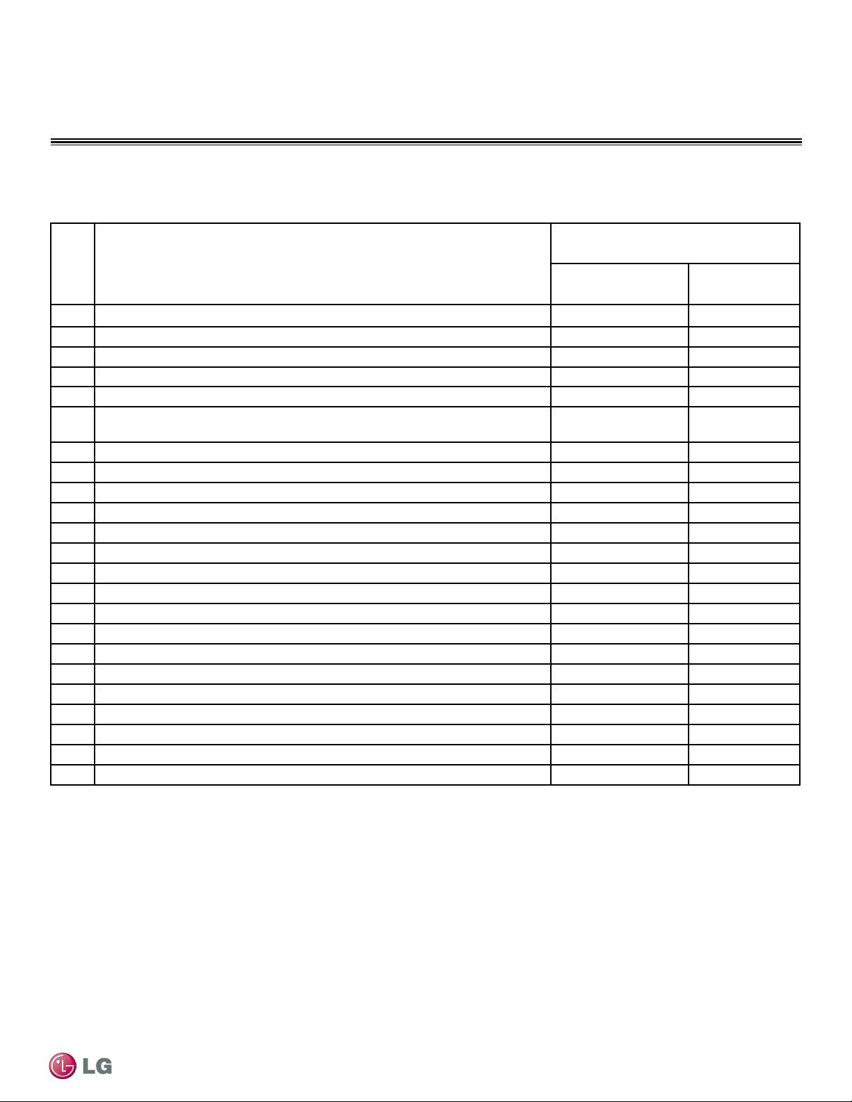
81
Troubleshooting
TROUBLESHOOTING
Due to our policy of continuous product innovation, some specifications may change without notification.
©LG Electronics U.S.A., Inc., Englewood Cliffs, NJ. All rights reserved. “LG” is a registered trademark of LG Corp.
Error Codes
Error
Code
Description
No. of Times Indoor Unit
LEDs Blink
LED1
(Plasma LED)
LED2
(Power LED)
21 DC Peak (IPM Fault); Compressor DC voltage was too high
2X 1X
22 Current Transformer2 (CT2) error; Alternating current (AC) input too high 2X 2X
23 DC Link Low Volt 2X 3X
25 AC Low/High Volt 2X 5X
26 DC Comp Position Error (not providing rotation), Locking 2X 6X
27
PSC Fault; Current to inverter compressor between AC and DC converter circuit
too high
2X 7X
28 Inverter compressor DC voltage is too high 2X 8X
29 Inverter compressor amperage is too high 2X 9X
31 Current-to-current transformer (CT) thermistor is too low 3X 1X
32 Inverter Compressor Discharge Pipe (D-Pipe) Overheat 3X 2X
40 CT Sensor Error; Thermistor is disconnected or shorted out 4X -
41 D-Pipe Sensor INV is disconnected or shorted out 4X 1X
44 Outdoor Air Sensor is disconnected or shorted out 4X 4X
45 Middle thermistor of outdoor unit condenser coil is disconnected or shorted out 4X 5X
46 Outdoor unit suction line thermistor is disconnected or shorted out 4X 6X
48 Outdoor unit coil outlet (liquid line) thermistor is disconnected or shorted out 4X 8X
53 Communication failure from outdoor unit to indoor unit 5X 3X
60 Outdoor unit printed circuit board (PCB) EEPROM check sum error 6X -
61 Outdoor unit condenser coil temperature is too high 6X 1X
62 Outdoor unit inverter compressor PCB heat sink temperature is too high 6X 2X
63 Condenser coil pipe thermistor temperature is too low 6X 3X
65 Heat sink thermistor has disconnected or has shorted out 6X 5X
67 Outdoor brushless direct current (BLDC) fan motor lock error 6X 7X
Table 32: Single Zone Wall Mounted Indoor Unit Error Codes - Continued
Troubleshooting Using Error Codes - Continued
Refer to Service Manuals posted on www.lghvac.com for a full description of all error codes and work-arounds.
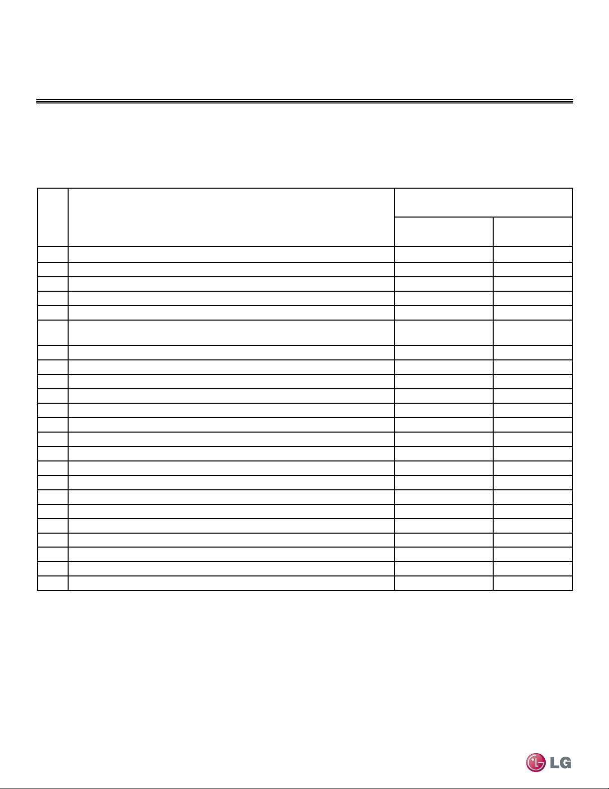
82
Single Zone High Efciency, Standard, Extended Pipe and Mega Wall Mount Installation Manual
Due to our policy of continuous product innovation, some specifications may change without notification.
©LG Electronics U.S.A., Inc., Englewood Cliffs, NJ. All rights reserved. “LG” is a registered trademark of LG Corp.
TROUBLESHOOTING
Error Codes
Table 33: Single Zone Wall Mounted Outdoor Unit Error Codes
Error
Code
Description
No. of Times Outdoor Unit
LEDs Blink
LED1
(Plasma LED)
LED2
(Power LED)
21 DC Peak (IPM Fault); Compressor DC voltage was too high
2X 1X
22 Current Transformer2 (CT2) error; Alternating current (AC) input too high 2X 2X
23 DC Link Low Volt 2X 3X
25 AC Low/High Volt 2X 5X
26 DC Comp Position Error (not providing rotation), Locking 2X 6X
27
PSC Fault; Current to inverter compressor between AC and DC converter circuit
too high
2X 7X
28 Inverter compressor DC voltage is too high 2X 8X
29 Inverter compressor amperage is too high 2X 9X
31 Current-to-current transformer (CT) thermistor is too low 3X 1X
32 Inverter Compressor Discharge Pipe (D-Pipe) Overheat 3X 2X
40 CT Sensor Error; Thermistor is disconnected or is shorted out 4X -
41 D-Pipe Sensor INV is disconnected or shorted out 4X 1X
44 Outdoor Air Sensor is disconnected or shorted out 4X 4X
45 Middle thermistor of outdoor unit condenser coil is disconnected or shorted out 4X 5X
46 Outdoor unit suction line thermistor is disconnected or shorted out 4X 6X
48 Outdoor unit coil outlet (liquid line) thermistor is disconnected or shorted out 4X 8X
53 Communication failure from outdoor unit to indoor unit 5X 3X
60 Outdoor unit printed circuit board (PCB) EEPROM check sum error 6X -
61 Outdoor unit condenser coil temperature is too high 6X 1X
62 Outdoor unit inverter compressor PCB heat sink temperature is too high 6X 2X
63 Condenser coil pipe thermistor temperature is too low 6X 3X
65 Heat sink thermistor has disconnected or has shorted out 6X 5X
67 Outdoor brushless direct current (BLDC) fan motor lock error 6X 7X
Single Zone Wall Mounted Outdoor Unit Error Codes
The Single Zone Wall Mounted outdoor unit error codes are visible on the outdoor unit, as well as, from the indoor unit. However, the indoor
unit error codes are only visible from the indoor unit and will not display at the outdoor unit. When troubleshooting the system, be sure to
verify if the error codes that are being displayed are specific for indoor or outdoor units.
Refer to Service Manuals posted on www.lghvac.com for a full description of all error codes and work-arounds.
83
Cautions for Refrigerant Leaks
CAUTIONS FOR REFRIGERANT LEAKS
Due to our policy of continuous product innovation, some specifications may change without notification.
©LG Electronics U.S.A., Inc., Englewood Cliffs, NJ. All rights reserved. “LG” is a registered trademark of LG Corp.
Amount of
Factory-Charged
Refrigerant per
Outdoor Unit
Amount of
Additional
Refrigerant
Trim Charge
Refrigerant Concentration Limit (RCL) Calculations
To calculate total refrigerant amount per system:
Cautions for Refrigerant Leaks / Introduction
ASHRAE Standards 15-2010 and 34-2010 offer guidelines that address refrigerant safety and the maximum allowable concentration of refrig-
erant in an occupied space. Refrigerant will dissipate into the atmosphere, but a certain volume of air is required for this to occur safely. For
R410A refrigerant, the maximum allowable concentration is 0.026 lbs./ft
3
per 1,000 ft
3
of air in an occupied space. Buildings with twenty-four
(24) hour occupancy allow half of that concentration.
1
ASHRAE Standards 15 and 34 assume that if a system develops a leak, its entire refrigerant charge will dump into the area where the leak
occurs. To meet ASHRAE Standards 15 and 34, calculate the refrigerant concentration that may occur in the smallest room volume on
the system, and compare the results to the maximum allowable concentration number (see following pages for information on how to calcu-
late the refrigerant concentration).
1
Also consult state and local codes in regards to refrigerant safety.
Verify the maximum refrigerant concentration level in the space where the indoor
unit will be mounted meets the concentration limit for the application.
1
American Society of Heating, Refrigeration and Air Conditioning Engi-
neers, Inc. (ASHRAE). Atlanta, GA. ASHRAE, Inc. Information about
ASHRAE Standard 15-2010 / 34-2010 and addenda current as of the date
of this publication.
Take appropriate actions at the end of HVAC equipment life to recover, recycle,
reclaim or destroy R410A refrigerant according to applicable US EPA rules.
Total System
Refrigerant
Charge
+ =
To calculate the potential refrigerant concentration level (RCL):
1. Measure the occupied space dimensions (in feet).
2. Calculate the cubic foot volume of air in the smallest occupied
space. (To obtain a detailed overview of the RCL, perform the
same calculations to the second smallest zone, the third smallest
zone until the RCL is obtained for all zones. Also, pay special
attention to areas such as basements, etc., where refrigerant
cannot dissipate easily.)
3. Divide the refrigerant charge of the Single Zone system serving
the area in pounds by the results of step 1.
4. If the calculation indicates that the potential refrigerant concen-
tration level is higher than the allowed RCL, increase the cubic
volume of the smallest occupied space or modify the piping
system design.
5. The allowable RCL limit for most applications must be equal to
or less than 0.026 lbs./ft
3
. However, in special occupied spaces,
such as hospitals and nursing homes, where occupants may have
limited mobility, the allowable RCL limit is cut in half. See ASHRAE
Standard 34-2007 and local codes for detailed information.
1
RCL (lbs./ft
3
) =
Total System Refrigerant Charge (lbs.)
Volume of Smallest Occupied Space (ft
3
)
Refrigerant Leaks
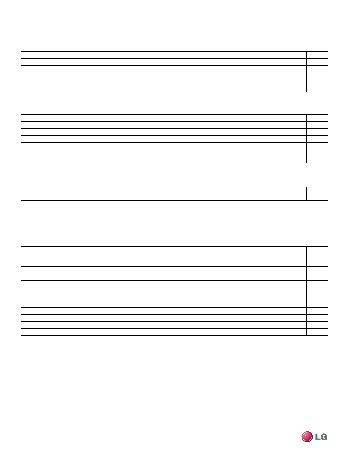
Due to our policy of continuous product innovation, some specifications may change without notification.
©LG Electronics U.S.A., Inc., Englewood Cliffs, NJ. All rights reserved. “LG” is a registered trademark of LG Corp.
84
Single Zone High Efciency, Standard, Extended Pipe and Mega Wall Mount Installation Manual
INSTALLATION CHECKLIST
PAGE 1
Major Component Rough-In
Description Check
Single Zone unit was connected properly per local code and the product installation procedures.
All literature and bagged accessories have been removed from the fan discharge.
Indoor unit was installed, properly supported, and located indoors in a non-corrosive environment.
Single Zone unit’s gravity condensate drain line was connected and routed where it properly drains away or, if installed in a me-
chanical room, was connected and properly routed to a drain terminal.
Piping and Insulation
Description Check
Copper
Over 5/8 inches—Rigid ACR only.
5/8 inches and under—Can use soft ACR.
15% silver brazing material only.
All refrigerant pipes and valves were insulated separately. Insulation butts up against the walls of the indoor units. No gaps or
cracks. Insulation was not compressed at clamps and hangers.
Brazing Practices
Description Check
Medical grade (there are 4 available) dry nitrogen for purging during brazing was used (constant 3 psi while brazing).
Installation
(For more information on any procedure, refer to the detail provided in the Indoor Unit Installation Manuals.)
Refrigerant Piping
Description Check
All pipe materials were properly stored, capped, and clean. All burrs were removed after cutting and pipe ends were reamed
before brazing.
During refrigerant pipe installation, for each segment of pipe, a record was made of the pipe length (including expansion loops,
offsets, double-back sections), and sizes, as well as the quantity and type of elbows used.
All long runs of straight pipe were provided with expansion loops.
A torque wrench and backup wrench were used to tighten all flare connections.
The back side of all flares were lubricated with a small drop of PVE refrigeration oil before tightening flare fittings.
Ensure all field made flares are 45°. Use factory-supplied flare nuts only.
Pipe segments were properly supported and all wall penetrations were sleeved.
Pipe insulation was not compressed at any point.
No oil traps, solenoid valves, sight glasses, filter driers, or any other unauthorized refrigerant specialties were present.
Best practice including a minimum of 20″ of straight pipe was installed between each elbow.
Due to our policy of continuous product innovation, some specifications may change without notification.
©LG Electronics U.S.A., Inc., Englewood Cliffs, NJ. All rights reserved. “LG” is a registered trademark of LG Corp.
85
Checklists
INSTALLATION CHECKLIST
PAGE 2
Condensate Pump / Drain Installation
Power Wire and Communications Cables
Description Check
Power wiring was connected to a single phase 208-230V source.
Ground wire was installed and properly terminated at the unit.
The power supplied was clean with voltage fluctuations within specifications. (±10% of nameplate).
Power wiring to the Single Zone outdoor unit was installed per all local electrical code requirements.
Power wiring to the indoor unit was installed per all local electrical code requirements.
LG-supplied cable was used between the indoor unit and its zone controller. No cables were spliced and no wire caps are
present.
Communication type RS-485–BUS type.
All communications cables were a minimum of 18-AWG, four (4) conductor, shielded, and stranded, with insulation material per
local code. Cable segment shields were tied together.
Used appropriate crimping tool to attach ring or spade terminals at all power wiring and control cable terminations.
All power and control wires were properly separated using the recommended distance provided in the product installation manual.
For further technical materials such as submittals, engineering
manuals, service manuals, and catalogs, visit www.lghvac.com.
LG Electronics U.S.A., Inc.
Commercial Air Conditioning Division
11405 Old Roswell Road
Alpharetta, Georgia 30009
www.lghvac.com
IM-WallMounted-ALL-08-14
LG Customer Information Center, Commercial Products
1-888-865-3026 USA
Follow the prompts for commercial A/C products.
20001747 ISO 9001: 2008
LG ELECTRONICS INC.