Loading ...
Loading ...
Loading ...
53
Refrigerant Piping Connections
Due to our policy of continuous product innovation, some specifications may change without notification.
©LG Electronics U.S.A., Inc., Englewood Cliffs, NJ. All rights reserved. “LG” is a registered trademark of LG Corp.
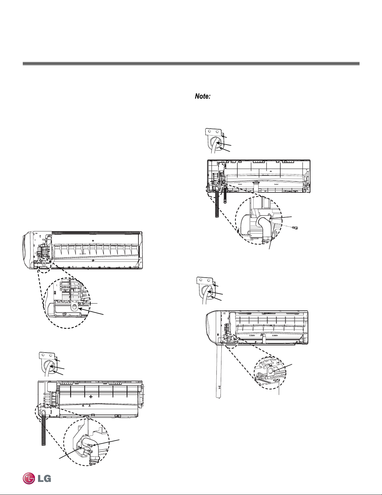
REFRIGERANT PIPING CONNECTIONS
1. Follow steps 1 through 6 on the previous page to connect piping
to the rear of the indoor unit.
HV3, HEV and HXV single-zone models require an additional conduit
“bracket/nut” to be installed at the rear of the indoor unit. Follow the
steps below for correct placement for your unit model.
2. Set the conduit by using the bracket and “D” screws from the
accessory kit. This must be done prior to permanent placement
of the piping to the rear of the unit, otherwise you won’t be able
to reach the conduit once piping and drain hose are in place and
anchored.
• For specific bracket placement, see each figure relating to the
specific single-zone model.
Type “D” Screws
HV3 Models
Conduit Bracket
Figure 60: Installing Bracket for Conduit (HV3)
Figure 61: Installing Bracket for Conduit (090HEV)
Figure 62: Installing Bracket for Conduit (120HEV)
Figure 63: Installing Bracket for Conduit (180HEV, 240HEV)
Piping to Indoor Unit - Conduit Bracket Placement (HV3, HEV)
Indoor Unit Connections - Conduit Bracket Placement
Pay attention to bracket placement on each single zone units. Your mod-
el might be slightly different from gure shown in this manual.
For specic bundling (taping) techniques of the Pipe and Drain Hose,
see Section, “Bundling and Cutting Line” on page 54.
090HEV
Conduit
Bracket
Type
“D” Screws
Nut
Bracket
Conduit
Type “D” Screws
Nut
Bracket
Conduit
120HEV
Conduit
Bracket
Type “D” Screws
180HEV, 240HEV
Nut
Bracket
Conduit
Conduit
Bracket
Loading ...
Loading ...
Loading ...