Loading ...
Loading ...
Loading ...
ALIGNMENTS AND ADJUSTMENT, Continued
WARNING
Keep appliance area clear and free from combustible
materials, gasoline, and other flammable vapors and liquids.
Do not obstruct the flow of ah _that is necessary for
combustion and ventilation.
4. Top Burner Valves
Top burner valves have orifices that are dedicated to the type of l\lel to be used These
orifices are not adjustable '[hey must be changed completely to convert fiom one gas to
the other DO NOT DISCARD TttE UNUSED ORIFICES fhey should be saved in
order to convert the range back to its original fuel
When converting the gas valves, the minimum flame adjustment screw must be adjusted
through the center of the valve stem You will need a 3/32" flat blade screw driver to
make this adjustment itold the valve stem and turn the adjustment screw until the proper
flame of approximately 1/8" is obtained
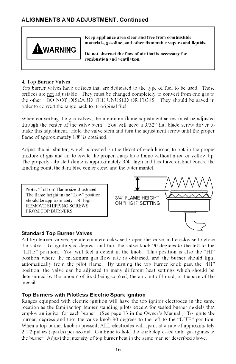
Adjust the air shutter, which is located on the throat of each burner, to obtain the proper
mixture of gas and air to create the proper sharp blue flame without a red or yellow tip
i'he properly adjusted flame is approximately 3/4" high and has three distinct cones; the
kindling point, the dark blue center cone, and the outer mantel
1'
/WW A
Note: %'ull on" flame size illustrated Y { , , }
The flame height in the _Lox_" position 3/4" FLAME HEIGHT
should be approxinlately 1 8" high [ j
REMOVE StIIPPING S CRE\\ S ON "HIGH" S ETTI NG
I,ROM "lOP BURNt RS
2>
Standard Top Burner Valves
All top burner valves operate counterclockxxise to open the valve and clockxxise to close
the valve To ignite gas depress and turn the valve knob 90 degrees to the left to the
LITE' position You will feel a detent in the knob This position is also the _[ti'
position where the maximum gas flow rate is obtained, and the burner should light
automatically l)om the pilot flame By turning the top burner knob past the _ti'
position the valve can be adjusted to many different heal settings xxhich should be
determined by the amount of food being cooked, the amount of liquid or the size of the
utensil
Top Burners with Pilotless Electric Spark Ignition
Ranges equipped xxith electric ignition xxill have the top ignitor electrodes in the same
location as the liuniliar top burner standing pilots except for sealed burner models that
employ an ignitor for each burner (See page 13 in the Oxxner's Manual) To ignite the
burner, depress and turn the valve knob 90 degrees to the left to the _ LITE" position
When a top burner knob is pressed, ALL electrodes will spark at a rate of approximately
2 1/2 pulses (sparks) per second Continue to hold the knob depressed until gas ignites at
the burner Adjust the intensity of top burner heat in the same manner described above
16
Loading ...
Loading ...
Loading ...