Loading ...
Loading ...
Loading ...
INSTALLATION STEP 6
InstalltheDoorControl
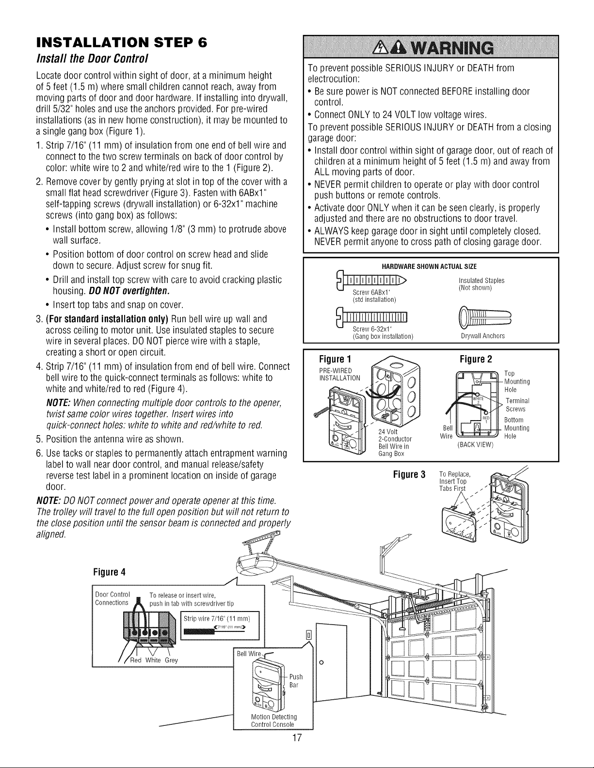
Locate door control within sight of door, at a minimum height
of 5 feet (1.5 m) where small children cannot reach, away from
moving parts of door anddoor hardware. If installing into drywall,
drill 5/32" holes and use the anchors provided. For pre-wired
installations (as in new home construction), it may be mounted to
a single gang box (Figure 1).
1. Strip 7/16" (11 mm) of insulation from one end of bell wire and
connect to the two screw terminals on back of door control by
color: white wire to 2 and white/red wire to the 1 (Figure 2).
2. Removecover by gently prying at slot in top of the cover with a
small flat head screwdriver (Figure 3). Fastenwith 6ABxl"
self-tapping screws (drywall installation) or 6-32x1" machine
screws (into gang box) as follows:
• Install bottom screw, allowing 1/8" (3 mm) to protrude above
wall surface.
• Position bottom of door control on screw headand slide
down to secure. Adjust screw for snug fit.
• Drill and install top screw with care to avoid cracking plastic
housing. DO NOTovertighten.
• Insert top tabs and snap on cover.
3 (For standardinstallation only) Run bell wire up wall and
across ceiling to motor unit. Useinsulated staples to secure
wire in severalplaces. DONOT pierce wire with a staple,
creating a short or open circuit.
4. Strip 7/16" (11 mm) of insulation from end of bell wire. Connect
bell wire to the quick-connect terminals as follows: white to
white andwhite/red to red(Figure 4).
NOTE:Whenconnecting multiple door controls to the opener,
twist samecolor wires together. Insert wires into
quick-connect holes: white to white and red/white to red.
5. Position the antenna wire as shown.
6. Usetacks or staples to permanently attach entrapment warning
label to wall near door control, and manual release/safety
reversetest label in a prominent location on inside of garage
door.
NOTE:DONOT connect power and operate opener at this time.
Thetrofley will travel to the furl open position but will not return to
the close position until the sensor beam is connected and properly
aligned.
To prevent possible SERIOUSINJURYor DEATHfrom
electrocution:
• Besure power is NOT connected BEFOREinstalling door
control.
• Connect ONLYto 24 VOLT low voltage wires.
To prevent possible SERIOUSINJURYor DEATHfrom a closing
garagedoor:
• Install door control within sight of garagedoor, out of reach of
children at a minimum height of 5 feet (1.5 m) and away from
ALL moving parts of door.
• NEVERpermit children to operate or play with door control
push buttons or remote controls.
• Activatedoor ONLYwhen it can be seen clearly, is properly
adjusted and there are no obstructions to door travel.
• ALWAYSkeep garage door in sight until completely closed.
NEVERpermit anyone to cross path of closing garagedoor.
HARDWARESHOWN ACTUALSIZE
(std installation)
_ ' I 'SJcJrle'_'__'3'2'_1'' '' ' ' J
(Gang box installation)
Insulated Staples
(Not shown)
Drywall Anchors
Figure1
PRE-WIRED It_JJl
INSTALLATION __
_ 24 Volt
I__- ._._'_t I 2-Conductor
_-Llt I Bell Wire in
Gang Box
Figure2
wB_._ T°p
Mounting
Hole
Terminal
Screws
Bottom
Mounting
Hole
(BACK VIEW)
Figure3 To Replace,
Insert Top ,
Tabs First
Figure4 ./l__
Door Control To release or insert wire,
Connections )ush in tab with screwdriver tip
Strip wire 7/16" (11 mm)
_,_7/16 (11 mrn)_
I
Red White Grey
J
17
Bell W_ o
Bar .---------
Motion Detecting
Control Console
Loading ...
Loading ...
Loading ...