
Loading ...
Loading ...
Loading ...
12
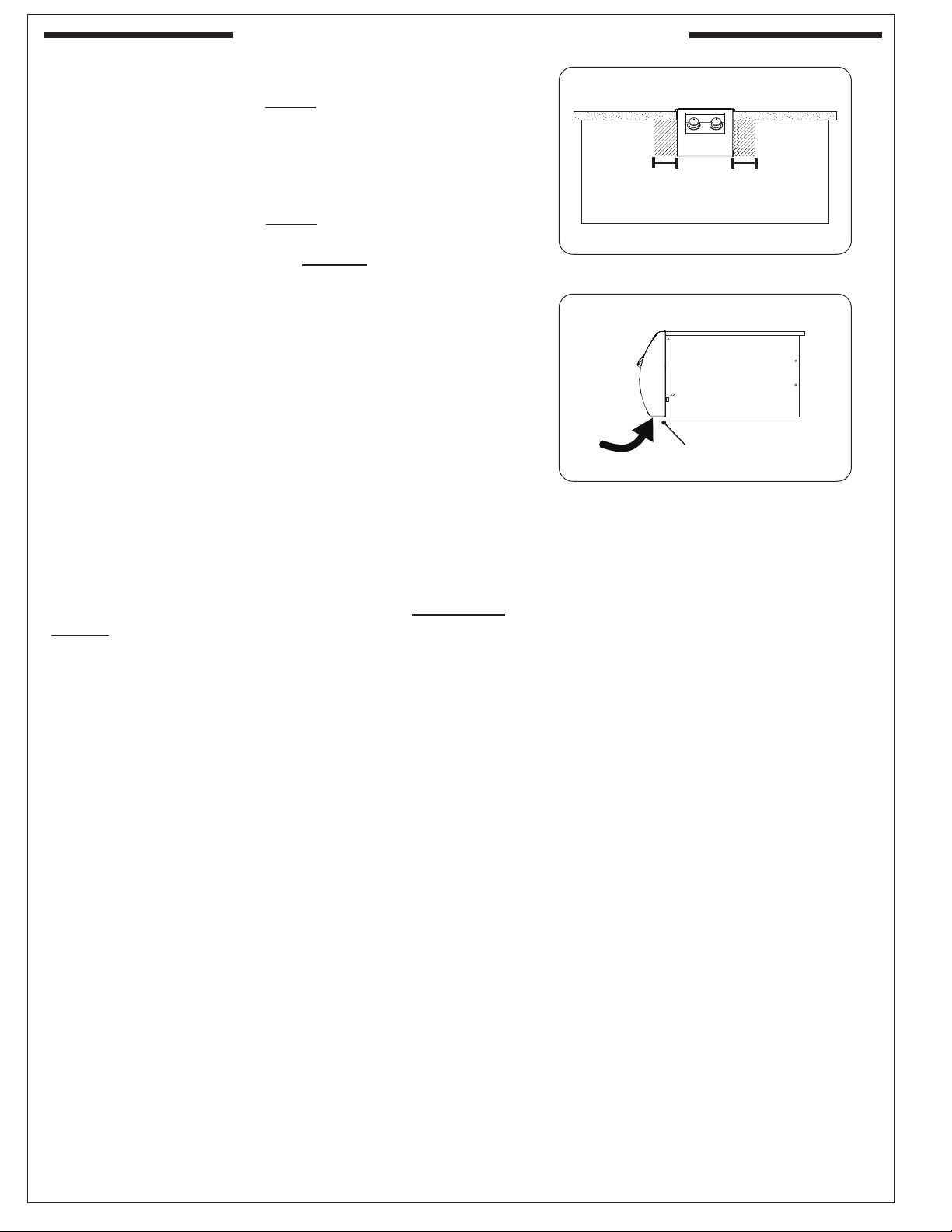
CONTROL PANEL CLEARANCES
• The control panel MUST have a minimum side
clearance of 6" from any obstructions/side walls. See
Fig. 12-1.
(To allow for access to light switch and control panel
removal.)
• The control panel MUST remain removable for
servicing (see CONTROL PANEL REMOVAL section).
Any adjacent countertops must not obstruct the panel
from being removed.
COMBUSTION AIR AND COOLING AIRFLOW
Proper airflow (front-to-back, Fig. 12-2) MUST be maintained
for the unit to perform as it was designed. If airflow is blocked,
overheating and poor combustion will result. Do not block the
1" front air inlet along the bottom of the control panel.
GAS-SUPPLY PLUMBING REQUIREMENTS
For natural gas or a household propane system, rigid
1
/
2
" or
3
/
4
" black steel pipe or local code-approved pipe is required
to conduct the gas supply to the unit. Contact your local gas
supplier. Connect this pipe to the required C.S.A.-approved
stainless-steel flex connector (attached). An NPT adapter
has been provided for
1
/
2
" pipe. DO NOT use a rubber hose
within the unit enclosure. Apply only joint compounds that
are resistant to all gasses on all NPT pipe fittings except flare
fittings. Make sure to tighten all fittings securely.
Note: If
1
/
2
" pipe is used with natural gas, it should be
no longer than 20'.
Important: A shut-off valve (not included) in the gas
line is required. It provides for safety when
the unit is not in use and for convenient
maintenance and repair. It must be installed
within 6 feet of the unit. If it is located within
the enclosure, it must be easily accessible.
Use a pipe joint compound resistant to
all gasses on all male fittings except flare
fittings.
GAS SUPPLY AND MANIFOLD PRESSURES:
For natural gas - normal 7" water column (w.c.), minimum
5", maximum 10
1
/
2
". For propane gas - normal 11" w.c.,
minimum 10", maximum 13".
INSTALLATION REQUIREMENTS (Cont.)
Fig. 12-2 Airflow diagram
(1" front air inlet)
Fig. 12-1 Control panel clearances
Min.
6"
Min.
6"
Loading ...
Loading ...
Loading ...