Loading ...
Loading ...
Loading ...
Important Installation Information:
• Attach anti-tip bracket to a solid wood cabinet having a
minimum wall thickness of 3/4" (19mm). The thickness
of the wall or floor may require use of longer screws,
available at your local hardware store.
• Use appropriate anchors when fastening the mounting
bracket to any material other than hard-wood or metal.
• In all cases, at least (2) of the bracket mounting screws
must firmly fasten the anti-tip bracket to the floor, and
(2) of the mounting screws (or drywall anchors) must
firmly fasten the anti-tip bracket to the rear wall (see
Figure 11 and Figure 12).
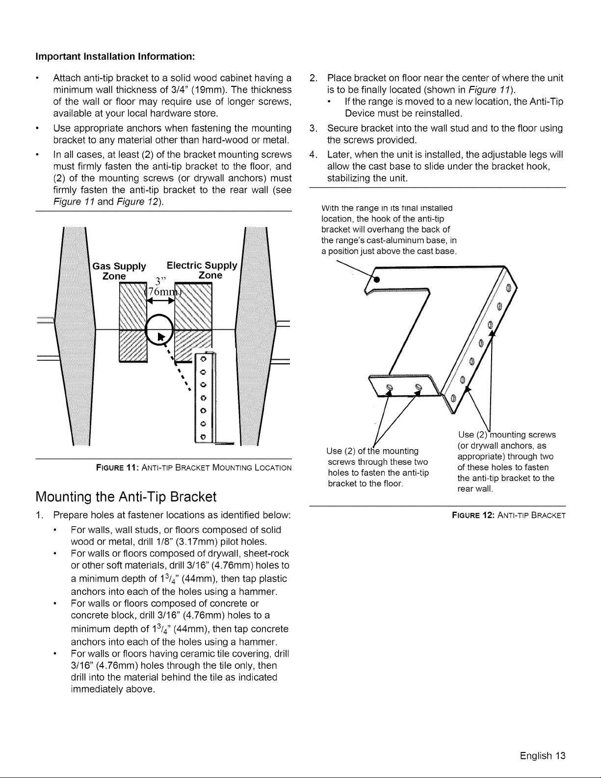
Gas Supply Electric Supply
Zone Zone
3 5_
,...Av_ 76mn l,J,.\
7.
$
$
o
0
FIGURE11: ANTI-TIP BRACKET MOUNTING LOCATION
Mounting the Anti-Tip Bracket
1. Prepare holes at fastener locations as identified below:
• For walls, wall studs, or floors composed of solid
wood or metal, drill 1/8" (3.17mm) pilot holes.
• For walls or floors composed of drywall, sheet-rock
or other soft materials, drill 3/16" (4.76mm) holes to
a minimum depth of 13/4 '' (44mm), then tap plastic
anchors into each of the holes using a hammer.
• For walls or floors composed of concrete or
concrete block, drill 3/16" (4.76mm) holes to a
minimum depth of 13/4" (44mm), then tap concrete
anchors into each of the holes using a hammer.
• For walls or floors having ceramic tile covering, drill
3/16" (4.76mm) holes through the tile only, then
drill into the material behind the tile as indicated
immediately above.
, Place bracket on floor near the center of where the unit
is to be finally located (shown in Figure 11).
• If the range is moved to a new location, the Anti-Tip
Device must be reinstalled.
3. Secure bracket into the wall stud and to the floor using
the screws provided.
4. Later, when the unit is installed, the adjustable legs will
allow the cast base to slide under the bracket hook,
stabilizing the unit.
VVtththe range in _tsfinal installed
location, the hook of the anti-tip
bracket wilt overhang the back of
the range's cast-aluminum base, in
a position just above the cast base.
Use (2) of mounting
screws through these two
holes to fasten the anti-tip
bracket to the floor.
Use (2 screws
(or drywall anchors, as
appropriate) through two
of these holes to fasten
the anti-tip bracket to the
rear wall.
FIGURE12: ANTI-TIP BRACKET
English 13
Loading ...
Loading ...
Loading ...