Loading ...
Loading ...
Loading ...
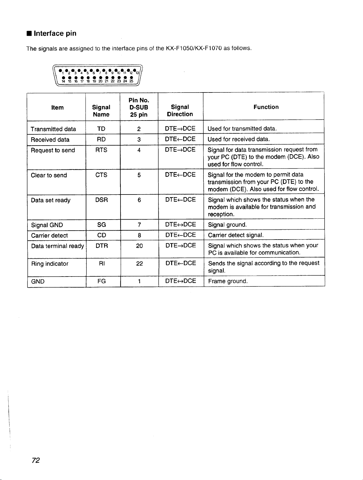
• Interface pin
The signals are assigned to the interface pins of the KX-F1050/K×-F1070 as follows.
o_• 2o_o_o_% o_• 8% o10o,,%%/_
O O O O O • • • • • • • //
14 15 16 17 18 19 20 21 22 23 24 25 //
s)
Item
Transmitted data
Received data
Request to send
Clear to send
Data set ready
Signal GND
Carrier detect
Data terminal ready
Ring indicator
GND
Signal
Name
TD
RD
RTS
CTS
DSR
SG
CD
DTR
RI
FG
Pin No.
D-SUB
25 pin
2
3
4
7
8
20
22
Signal
Direction
DTE_DCE
DTE_-DCE
DTE_DCE
DTE_DCE
DTE_DCE
DTE_--_DCE
DTE_DCE
DTE_DCE
DTE_DCE
DTEe-_DCE
Function
Used for transmitted data.
Used for received data.
Signal for data transmission request from
your PC (DTE) to the modem (DCE). Also
used for flow control.
Signal for the modem to permit data
transmission from your PC (D'I-E) to the
modem (DCE). Also used for flow control.
Signal which shows the status when the
modem is available for transmission and
reception.
Signal ground.
Carrier detect signal.
Signal which shows the status when your
PC is available for communication.
Sends the signal according to the request
signal.
Frame ground.
72
Loading ...
Loading ...
Loading ...