Loading ...
Loading ...
Loading ...
BOTH MODELS
SQUARING THE BLADE TO THE TABLE
i
WARNING: To avoid Injury from unexpected|
starting, make sure power cord Is unplugged
]
before making adjustments to band saw parts,
To assure repeatability and accuracy, it is important
to square the blade to the table and adjust the 0°
position stop This will guarantee that the blade will
return to the square position after the head has been
moved for a bevel cut
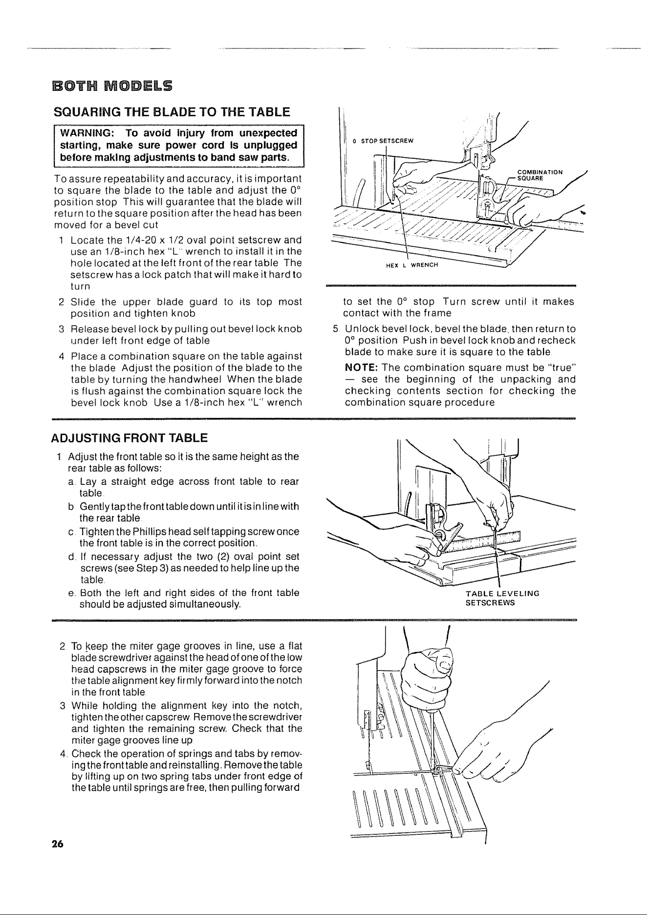
1 Locate the 1/4-20 x 1/2 oval point setscrew and
use an 1/8-inch hex "L wrench to install it in the
hole located at the left front of the rear table The
setscrew has a lock patch that will make it hard to
turn
2 Slide the upper blade guard to its top most
position and tighten knob
3 Retease bevel lock by pulling out bevel lock knob
under feft front edge of table
4 Place a combination square on the table against
the blade Adjust the position of the blade to the
table by turning the handwheel When the blade
is flush against the combination square Iock the
beve! lock knob Use a 1/8-inch hex "L" wrench
ADJUSTING FRONT TABLE
0sTo,.,..,w
_ COMBINATION
J i: SQUARE
to set the 0° stop Turn screw until it makes
contact with the frame
Unlock bevel lock, bevel the blade, then return to
0° position Push in bevel lock knob and recheck
blade to make sure it is square to the table
NOTE: The combination square must be "true"
-- see the beginning of the unpacking and
checking contents section for checking the
combination square procedure
Adjust the front table so it is the same height as the
rear table as follows:
a. Lay a straight edge across front table to rear
table
b Gently tap the front table down until itis in tine with
the rear table.
c Tighten the Phillips head self tapping screw once
the front table is in the correct position,.
d If necessary adjust the two (2) oval point set
screws (see Step 3) as needed to help line up the
table.
e. Both the teft and right sides of the front table
should be adjusted simultaneously.
TABLE LEVELING
SETSCREWS
2 To !(eep the miter gage grooves in line, use a flat
blade screwdriver against the head of one ofthe tow
head capscrews in the miter gage groove to force
the table align ment key firrely forward into the notch
in the front table
3 While holding the alignment key into the notch,
fighten the other capscrew Remove the screwdriver
and tighten the remaining screw. Check that the
miter gage grooves line up
4. Check the operation of springs arid tabs by remov-
ing the front table and reinstalling. Remove the table
by lifting up on two spring tabs under-front edge of
the table until springs are free, then pulling forward
26
Loading ...
Loading ...
Loading ...