
Wi-Fi Series - 1080p
Smart Security System
INSTRUCTION MANUAL

Click for contents
2
Important Information
FCC Verification
This equipment has been tested and found to comply with the limits for Class
B digital device, pursuant to part 15 of the FCC Rules. These limits are de-
signed to provide reasonable protection against harmful interference in a
residential installation. This equipment generates, uses and can radiate ra-
dio frequency energy and, if not installed and used in accordance with the
instructions, may cause harmful interference to radio or television reception,
which can be determined by turning the equipment off and on, the user is
encouraged to try to correct the interference by one or more of the following
measures:
· The antennas used with this transmitter must be installed to provide a min-
imum separation distance of at least 20 cm from all persons and must not be
co-located or operating in conjunction with any other antenna or transmitter,
except in accordance with FCC multi- transmitter product procedures
· Increase the separation between the equipment and the receiver
· Connect the equipment into an outlet on a circuit different from that to
which the receiver is connected
· Consult the dealer or an experienced radio/TV technician for help
These devices comply with part 15 of the FCC Rules. Operation is subject to
the following two conditions:
· These devices may not cause harmful interference
· These devices must accept any interference received, including interfer-
ence that may cause undesired operation
Important Notice: All jurisdictions have specific laws and regulations relat-
ing to the use of cameras. Before using any camera for any purpose, it is the
buyer’s responsibility to be aware of all applicable laws and regulations that
prohibit or limit the use of cameras and to comply with the applicable laws
and regulations.
FCC Regulation (for USA): Prohibition against eavesdropping
Except for the operations of law enforcement officers conducted under lawful
authority, no person shall use, either directly or indirectly, a device operated
pursuant to the provisions of this Part for the purpose of overhearing or re-
cording the private conversations of others unless such use is authorized by
all of the parties engaging in the conversation.
Important Safety Instructions
· Do not operate if wires and terminals are exposed
· Do not cover vents on the side of your device and allow adequate space for
ventilation
· Only use the power adapter supplied with your NVR
About this Instruction Manual
This instruction manual is written for the Wi-Fi NVR 490 series and was ac-
curate at the time it was completed. However, because of our on-going ef-
forts to constantly improve our products, additional features and functions
may have been added since that time.
Important Password Information
This NVR does not have a default password. A password is created dur-
ing the Wizard. If password protection has been enabled and you have
forgotten your password, your NVR’s MAC address can be used to create
a new password (see page 3 - Password Recovery).
Click for contents
3
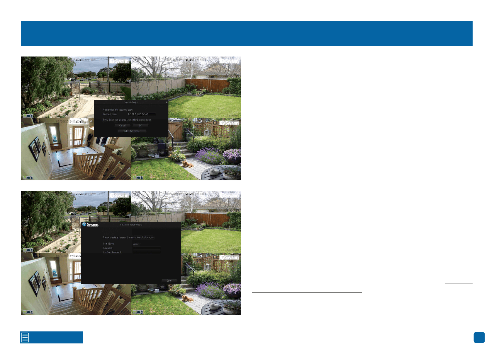
Password Recovery
Forgotten your password? Please do the following:
1.
Right-click the mouse on the Live View screen to display the Menu Bar
then click “Menu”.
2. At the password login screen click “Forgot Password”.
3. A message will appear on-screen. Follow the instructions to receive the
password recovery code via email. This will contain your NVR’s MAC address
(if it’s not in your inbox, check your junk or spam folder).
4. Input the MAC address including the colons (see left example) then click
“OK”.
5. A message will appear on-screen stating that your password has been
reset. Click “OK” to create a new password.
6. Enter a new password (see bottom left example). The password has to
be a minimum of six characters and can contain a mixture of numbers and
letters. Use a password that you are familiar with, but is not easily known to
others.
7. Write down your password in the space provided below for safe keeping.
8. When finished click “Save”. A message will appear on-screen. Click “OK”
to finish.
Don’t forget to write down your password: __________________________
I haven’t created an email for my NVR, what can I do? Don’t worry, you can
use SwannView Link to retrieve your recovery code (see page 63 - Resetting
your Password using SwannView Link).
08/04/2019 12:30:15 pm MON
Backyard
08/04/2019 12:30:15 pm MON
Front door
08/04/2019 12:30:15 pm MON
Staircase
08/04/2019 12:30:15 pm MON
Side gate
08/04/2019 12:30:15 pm MON
Backyard
08/04/2019 12:30:15 pm MON
Front door
08/04/2019 12:30:15 pm MON
Staircase
08/04/2019 12:30:15 pm MON
Side gate

Contents
4
Important Information ������������������������������������������������������������������������������������������ 2
Password Recovery ����������������������������������������������������������������������������������������������� 3
Live View ���������������������������������������������������������������������������������������������������������������� 6
Live View Mode ������������������������������������������������������������������������������������������������������ 7
Live View Icons & Controls ����������������������������������������������������������������������������������� 8
Menu ����������������������������������������������������������������������������������������������������������������������� 9
Menu Layout ��������������������������������������������������������������������������������������������������������� 10
Camera Configuration ��������������������������������������������������������������������������������������� 11
Recording: Encode - Main Stream �������������������������������������������������������������������� 12
Recording: Encode - Sub Stream ���������������������������������������������������������������������� 13
Channel: Managing Cameras ���������������������������������������������������������������������������� 14
Channel: Adding a Camera in AP Mode ����������������������������������������������������������� 15
Channel: Adding a Camera in Station Mode ���������������������������������������������������� 16
Motion ������������������������������������������������������������������������������������������������������������������� 17
Motion Detection Setup �������������������������������������������������������������������������������������� 18
Motion: Schedule ������������������������������������������������������������������������������������������������� 19
Motion Detection Tips ����������������������������������������������������������������������������������������� 20
Thermal-Sensing Camera Tips ������������������������������������������������������������������������� 21
Configuring your Swann PT Cam (SWWHD-PTCAM) ������������������������������������� 22
Controlling your Swann PT Cam ����������������������������������������������������������������������� 24
Creating a Preset ������������������������������������������������������������������������������������������������� 25
Recording Configuration ����������������������������������������������������������������������������������� 26
Recording: Schedule ������������������������������������������������������������������������������������������� 27
Playback & Backup ��������������������������������������������������������������������������������������������� 28
Search: Video Search ������������������������������������������������������������������������������������������ 29
Playback Interface ����������������������������������������������������������������������������������������������� 30
Search: Backup ���������������������������������������������������������������������������������������������������� 32
System Configuration ���������������������������������������������������������������������������������������� 33
System: General �������������������������������������������������������������������������������������������������� 34
Daylight Saving ���������������������������������������������������������������������������������������������������� 35
System: Disk ��������������������������������������������������������������������������������������������������������� 36
System: Maintenance ������������������������������������������������������������������������������������������ 37
Network: General ������������������������������������������������������������������������������������������������ 38
Network: Advanced ��������������������������������������������������������������������������������������������� 39
Email Settings ������������������������������������������������������������������������������������������������������ 40
Network: Wi-Fi Setting (AP Mode) �������������������������������������������������������������������� 41
Network: Wi-Fi Setting (Station Mode) ������������������������������������������������������������� 42
System: System Information ������������������������������������������������������������������������������ 43
AlwaysSafe ���������������������������������������������������������������������������������������������������������� 44
Live View ��������������������������������������������������������������������������������������������������������������� 45
Devices ������������������������������������������������������������������������������������������������������������������ 47
Device Settings: Basic Information/Network �������������������������������������������������� 48
Device Settings: Video & Audio �������������������������������������������������������������������������� 49
Device Settings: Display �������������������������������������������������������������������������������������� 50
Device Settings: Storage - Record Schedule ��������������������������������������������������� 52
Device Settings: Storage - HDD ������������������������������������������������������������������������� 53
Device Settings: Alarm - MD Settings �������������������������������������������������������������� 54
Motion Detection Sensitivity ������������������������������������������������������������������������������� 55
Motion Detection Schedule �������������������������������������������������������������������������������� 56
Device Settings: Account Security ��������������������������������������������������������������������� 57

Contents
5
Device Settings: Notification ������������������������������������������������������������������������������ 58
Device Settings: Upgrade ����������������������������������������������������������������������������������� 59
Device Settings: System ������������������������������������������������������������������������������������� 60
Controlling your Swann PT Cam ����������������������������������������������������������������������� 61
Playback ���������������������������������������������������������������������������������������������������������������� 62
Resetting your Password using SwannView Link ������������������������������������������� 63
Frequently Asked Questions ������������������������������������������������������������������������������ 65
Glossary ���������������������������������������������������������������������������������������������������������������� 67
Warranty Information ������������������������������������������������������������������������������������������ 72
Help & Resources ������������������������������������������������������������������������������������������������ 73
6
Click for contents
Live View
Live View is the default display mode for
your NVR. Each camera connected will
be displayed on-screen. You can check
the status or operation of your NVR and
cameras using the icons and Menu Bar
on the Live View screen. Right-click the
mouse to access the Menu Bar.
08/04/2019 12:30:15 pm MON
Front door
08/04/2019 12:30:15 pm MON
Backyard
08/04/2019 12:30:15 pm MON
Front door
08/04/2019 12:30:15 pm MON
Staircase
08/04/2019 12:30:15 pm MON
Side gate
Click for contents
7
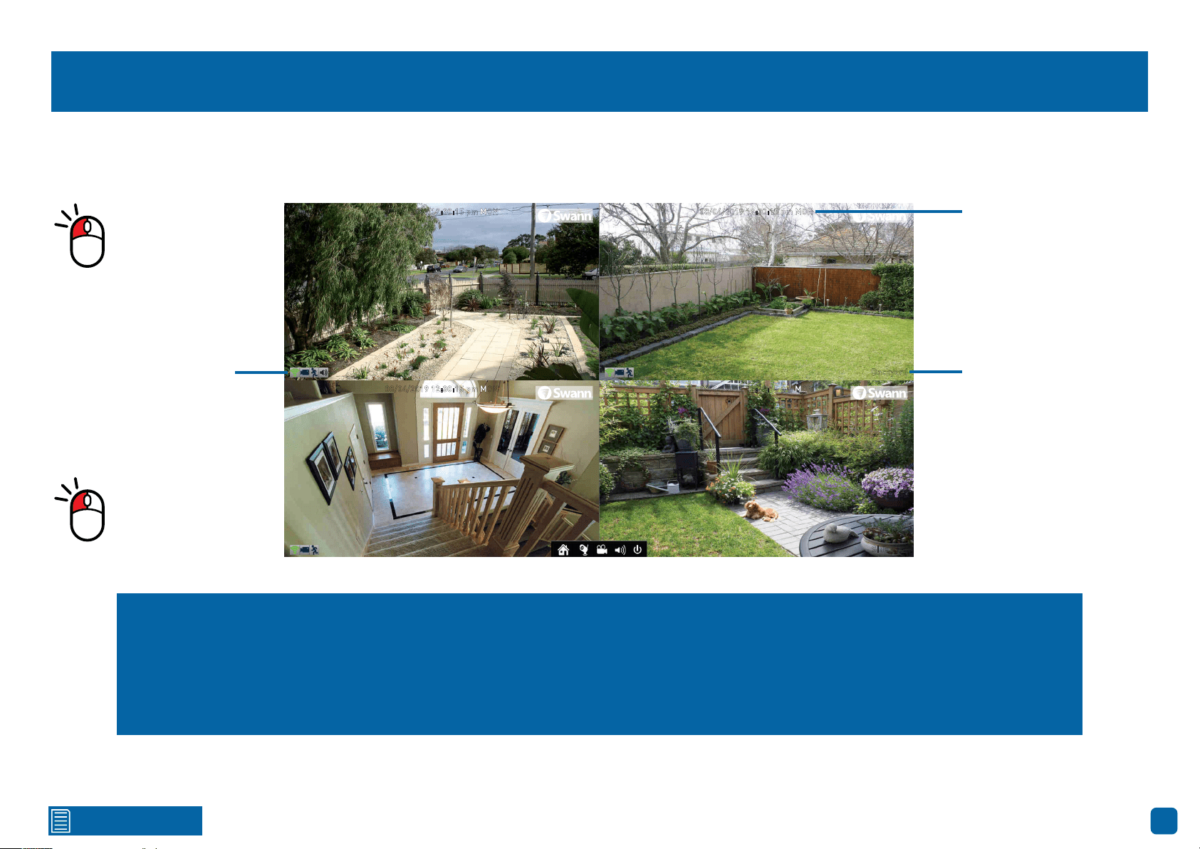
Live View Mode
Live View mode is the default display for your NVR. Each camera connected will be displayed. You can check the operation of your NVR by using the status
icons on the Live View screen. You can also access the Menu to adjust settings for Recording, Motion and to search and play previously recorded videos.
Status Icons
Double-click a live
video channel to
view full screen.
08/04/2019 12:30:15 pm MON
Backyard
08/04/2019 12:30:15 pm MON
Front door
08/04/2019 12:30:15 pm MON
Staircase
08/04/2019 12:30:15 pm MON
Side gate
Click & drag a live
video channel to
reposition it.
Menu: Open the Menu to access the various settings and options
available (right-click the mouse on the Live View screen to display
the Menu Bar).
Channel: Opens the Device List that displays the cameras that
are currently connected or to scan for new cameras.
Search: Click to search and play back previously recorded videos.
Audio: Click to enable or disable live audio playback. Only one
camera channel can be enabled at a time for live audio.
Shutdown: Click to Lock (password must be enabled for this op-
tion to work), Shutdown or Reboot your NVR.
Date & Time
Camera Name
Click for contents
8
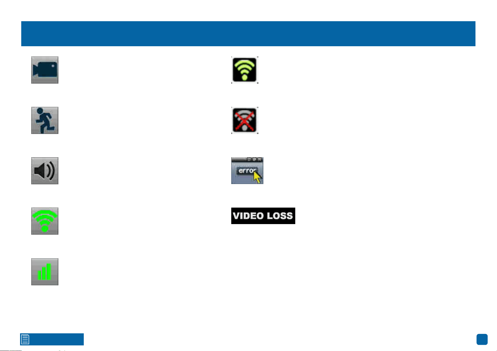
Live View Icons & Controls
The record icon indicates that your NVR is currently
recording the camera’s video stream.
The motion icon indicates that your NVR is detecting
motion from the camera.
The audio icon indicates that the camera is selected
for live audio (click the “Audio” button on the Menu
Bar to enable).
This Wi-Fi icon indicates that the camera is commu-
nicating with your NVR. It also indicates the Wi-Fi
signal strength.
This Wi-Fi icon indicates that your NVR is running
in Station mode and is wirelessly connected to your
network. It also indicates the Wi-Fi signal strength.
This Wi-Fi icon indicates that your NVR has been dis-
connected from your wireless network or may be out
of range.
This indicates that the channel
displaying this message, has lost the
feed from its camera.
The network icon indicates that a camera is physi-
cally connected to your network via its Ethernet con-
nection.
This icon will appear on-screen when there is
a notification or error. Click the icon to view the
message.
9
Click for contents
Menu
The “Menu” is where you control the various
actions and options that are available on your
NVR, such as adjusting settings for motion
detection and changing network modes. You
can also access previously recorded video for
playback and to copy to a storage device such
as a USB flash drive. To maintain system in-
tegrity, a firmware upgrade can be performed
when available.
Click for contents
10
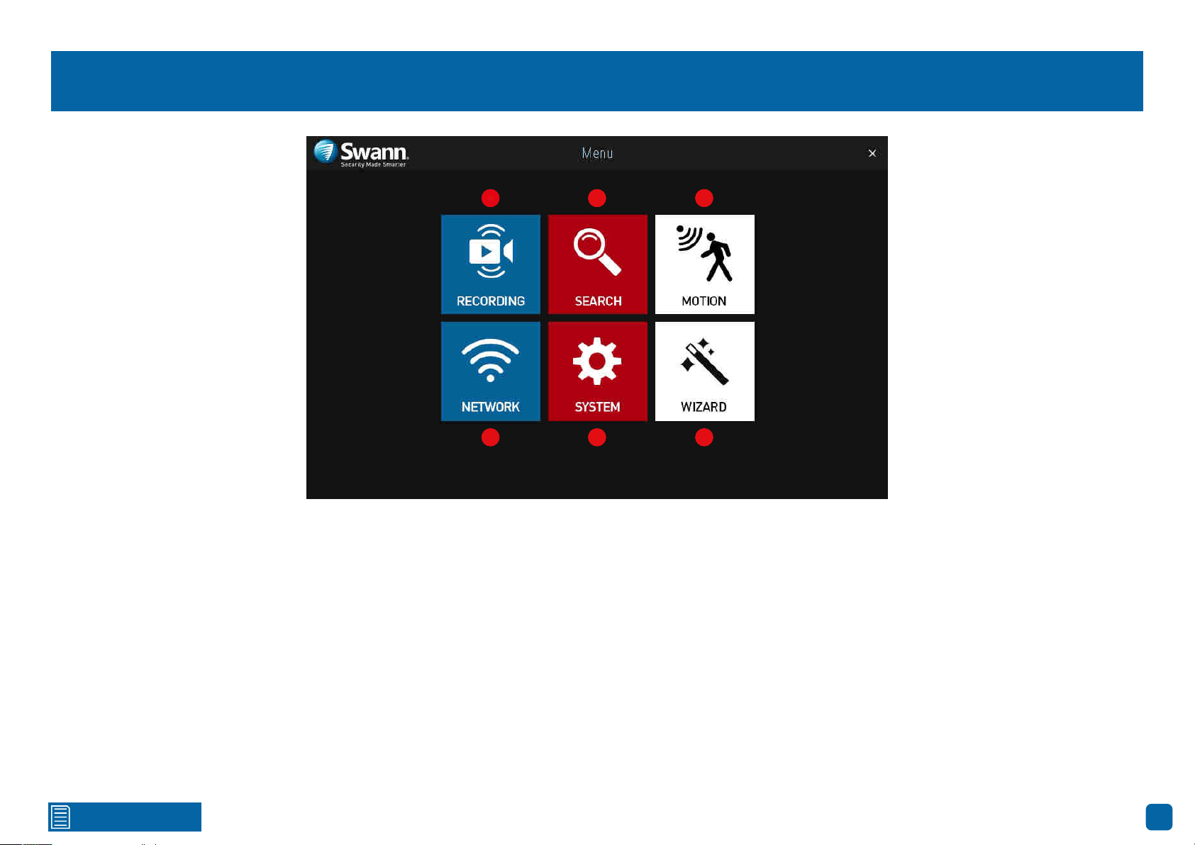
Menu Layout
1. Recording: This function allows you to adjust settings for the camera such
as camera name, encoding settings for Main Stream and Sub Stream as well
as changing the bitrate and frame rate. You can also change the schedule for
both normal and motion recording.
2. Search: This function allows you to search and play back previously re-
corded videos. You’re presented with an overview of video recorded on a par-
ticular day for a particular month for each channel on your NVR. You can also
backup events to a USB flash drive.
3. Motion: Motion is the default recording mode for your NVR. The entire view
of the camera is enabled to detect motion however you can select certain ar-
eas if you wish. The sensitivity and schedule can also be changed according
to your needs. When motion is detected, you can enable your NVR to send you
an email notification and/or sending push notifications via the AlwaysSafe
app.
4. Network: This function gives you access to the various network options
available including your email settings. The option to change to Station mode
can also be done here.
5. System: This function gives you access to the various system settings
such as language selection, display resolution, Daylight Saving, formatting
the hard drive (or MicroSD card if one has been included) and upgrading the
firmware.
6. Wizard: Click this to access the Wizard.
1 2 3
4 5 6
1 2 3
4 5 6
1 2 3
654

11
Click for contents
Camera Configuration
The camera configuration options are avail-
able in the “Recording” and “Motion” men-
us and by clicking the “Channel” button on
the Menu Bar. You can change the camera
name, alter the encoding settings for Main
Stream and Sub Stream, change the bitrate
and frame rate and assign a different channel
number for each camera detected. The de-
fault motion detection area and schedule can
also be changed. You can also add additional
cameras in AP or Station mode and use the
PTZ controls with compatible cameras.
Click for contents
12
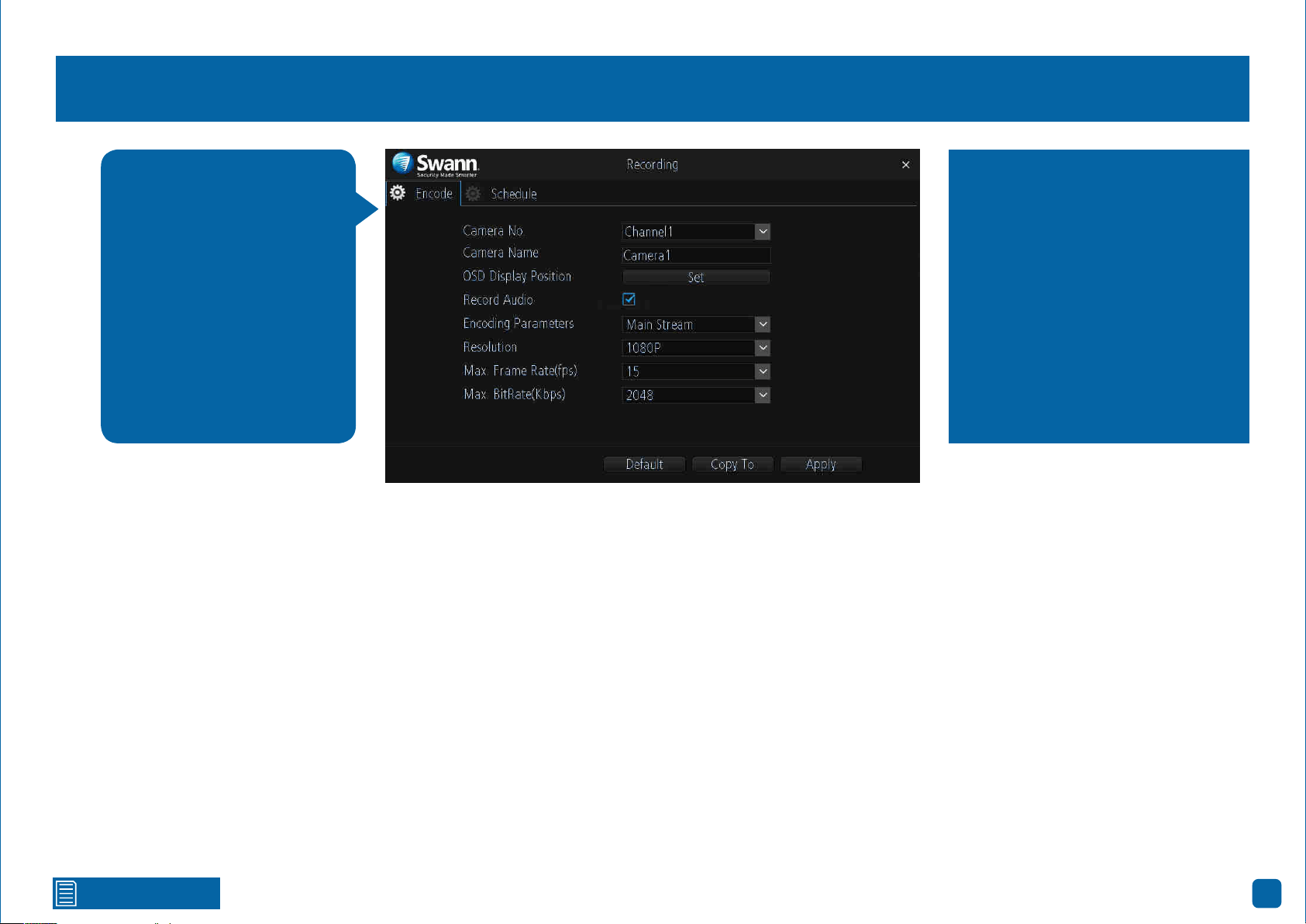
Recording: Encode - Main Stream
Camera No.: Select a camera that you would like to configure.
Camera Name: Enter a name for the camera you’ve selected. It can be up to
16 characters in length.
OSD Display Position: Allows you to change the position of the on-screen
display. Click the “Set” button to change. Use the mouse to reposition the
camera name. Right-click the mouse then click “Save” to exit.
Record Audio: This is enabled by default and allows sound from your camer-
as to be recorded with the video stream. Click the checkbox if audio recording
is not required.
Encoding Parameters: Select which parameter that you would like to config-
ure - Main Stream or Sub Stream.
Resolution: The default resolution is 1080P. A lower resolution is available
which can allow you to record at a higher frame rate (up to 25fps).
Max. Frame Rate (fps): The number of frames per second (fps) that your
NVR will record. The default is 15fps, however you can change this if needed.
Max. BitRate (Kbps): The maximum bitrate is 3072Kbps and the default bi-
trate is 2048Kbps. Lowering the bitrate may improve signal reliability if your
Wi-Fi signal is poor but this also reduces video quality. Increasing the bitrate
improves video quality if there is a lot of movement but needs a strong Wi-Fi
signal.
→ Click the “Default” button to revert back to default settings.
→ Use the “Copy to” button to apply all settings to the other cameras.
→ Don’t forget to click “Apply” to save settings.
The functions available allow
you to change the resolution,
frame rate and bitrate for
each camera connected. By
default the recording reso-
lution, frame rate and bitrate
are automatically selected to
fit in with the capabilities of
the provided cameras, how-
ever you can change them if
required.
Higher Main Stream bitrates need
the best Wi-Fi signal and will also
consume the storage space faster,
but can give you higher quality vid-
eo if there is a lot of movement in
the scene. You can also reduce the
bitrate to improve the Wi-Fi signal.
If you locate your cameras a longer
distance from your Wi-Fi network,
you may have to use lower bitrates
to get a reliable connection.

Click for contents
13
Recording: Encode - Sub Stream
Camera No.: Select a camera that you would like to configure.
Camera Name: Enter a name for the camera you’ve selected. It can be up to
16 characters in length.
OSD Display Position: Allows you to change the position of the on-screen
display. Click the “Set” button to change. Use the mouse to reposition the
camera name. Right-click the mouse then click “Save” to exit.
Record Audio: This is enabled by default and allows sound from your camer-
as to be recorded with the video stream. Click the checkbox if audio recording
is not required.
Encoding Parameters: Select which parameter that you would like to config-
ure - Main Stream or Sub Stream. By default, the AlwaysSafe app utilises the
Sub Stream parameter to stream video from your NVR to your mobile device.
Resolution: The default resolution is 640 x 360 and cannot be changed.
Max. Frame Rate (fps): The default frame rate is 6fps. Increasing the Sub
Stream frame rate may improve playback smoothness when streaming but
can also reduce the overall video quality when viewed on your mobile device.
Some experimentation is required to get the optimal viewing experience.
Max. BitRate (Kbps): The maximum bitrate is 512Kbps and the default bi-
trate is 64Kbps. Increasing the bitrate will improve the video quality when
viewed on your mobile device, but needs a fast internet upstream speed for
the best remote viewing experience. Some experimentation is required to get
the optimal viewing experience.
→ Click the “Default” button to revert back to default settings.
→ Use the “Copy to” button to apply all settings to the other cameras.
→ Don’t forget to click “Apply” to save settings.
The functions available al-
low you to control how video
is streamed to your mobile
device using the AlwaysSafe
app. You can change the res-
olution, frame rate and bi-
trate if you’re having issues
streaming live video from
your NVR.
Change the Sub Stream bitrate if
you’re having issues such as video
buffering or slow frame rates when
streaming to your mobile device.
By lowering the bitrate, you reduce
the amount of data that is trans-
mitted over the internet which can
improve the video you see on your
mobile device when you are away
from home. Some high speed in-
ternet connections allow higher bi-
trates to be used.
Click for contents
14
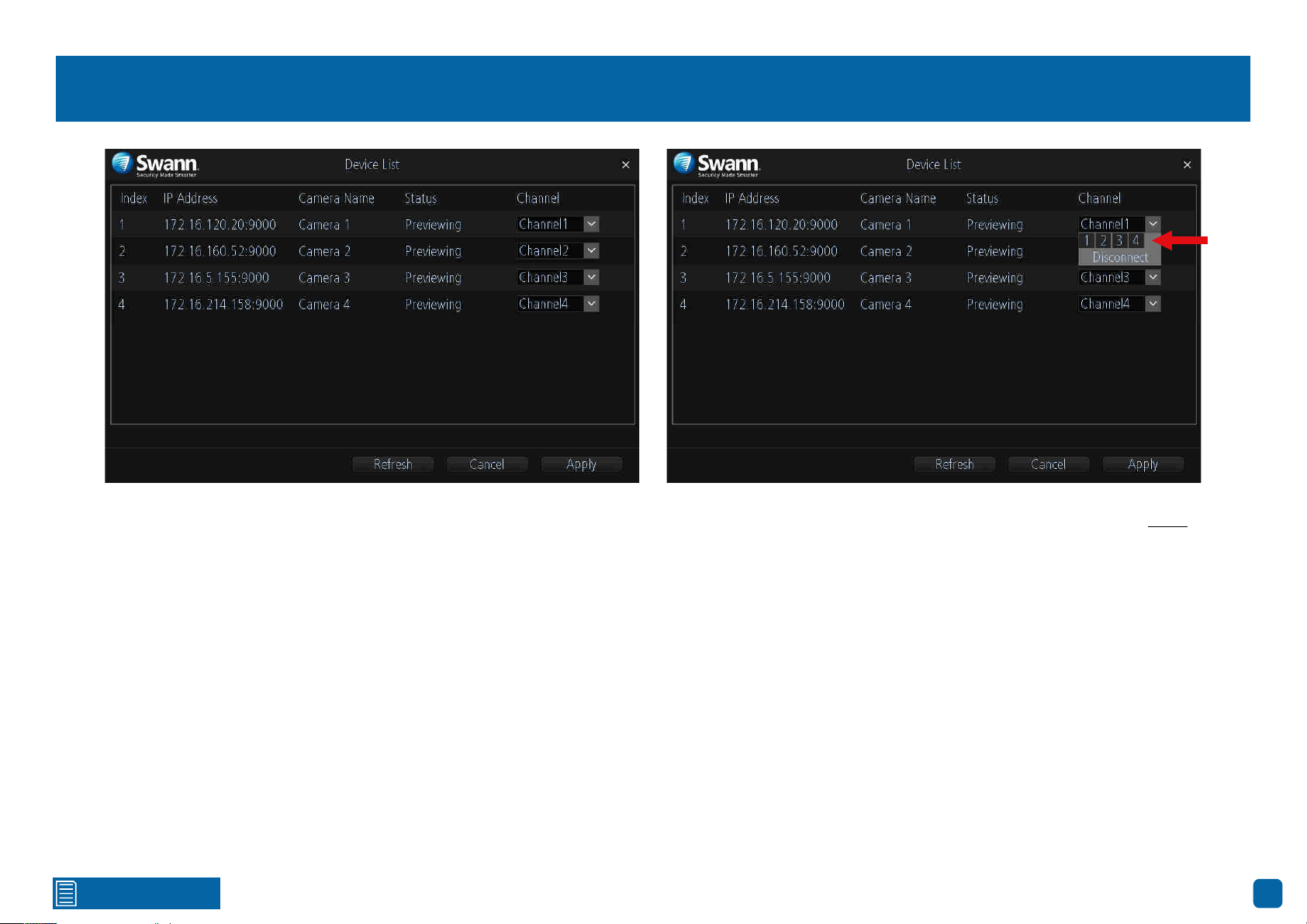
Channel: Managing Cameras
Accessing the Device List displays the cameras that are currently configured,
the IP address and status for each camera as well as the ability to assign a
different channel number or to disconnect a camera.
You can also permanently change the position the camera is viewed in Live
View mode, for example, a camera installed at the front entrance is currently
assigned to Channel4 (bottom right in Live View mode), and you would prefer
if this was positioned top left which is assigned to Channel1 (you can change
the camera position in Live View mode, however rebooting the NVR will revert
back to the original position).
Channel1: Top left, Channel2: Top right, Channel3: Bottom left, Channel4:
Bottom right
To access the Device List, right-click the mouse in Live View mode to access
the Menu Bar then click the “Channel” button.
When assigning a different channel number, each camera must have a
unique number, they cannot share a channel number.
If you have removed a camera and/or adding a new one, in the line of the
old camera, click the down facing arrow on said camera and click the empty
square (Disconnect) next to (4) as shown above.
→ Click the “Refresh” button to refresh the Device List.
→ Click the “Cancel” button to exit.
→ Don’t forget to click “Apply” to save settings.
Click for contents
15
Channel: Adding a Camera in AP Mode
By default, the cameras ship ready to connect to your NVR’s default Wi-Fi
settings. Simply connect each camera to power and wait about a minute. You
will see the camera in Live View mode.
If your NVR’s Wi-Fi settings have changed, please do the following:
1. In Live View mode, right-click the mouse to access the Menu Bar then click
the “Menu” button.
2. Click “Network” then click “Wi-Fi Setting”. You will see a QR code dis-
played (as shown above).
3. Click and hold the camera’s reset/pair button until you hear a message
from the camera’s speaker.
4. Take your camera and face it towards the QR code to scan (you may need
to get close to the screen to scan). When successful, you will hear a beep and
the voice will announce that the scan is successful. After a short moment,
you will see the camera in Live View mode.
Repeat these steps for any additional cameras that you have.
→ Click the “Help” button for instructions on how to sync Wi-Fi settings to
your cameras.
→ Click the “Default” button to revert back to default settings.
→ Don’t forget to click “Apply” to save settings.
Click for contents
16
Channel: Adding a Camera in Station Mode
It’s recommended that you add cameras to your NVR when it’s in AP mode
(see page 15 - Channel: Adding a Camera in AP Mode) before changing to
Station mode.
1. When all cameras have been added to your NVR, for Wi-Fi Mode click the
drop down menu and select “Station” (as shown above).
2. After a short moment, a list of Wi-Fi access points that your NVR detects,
will be shown. Select your Wi-Fi access point then click the next button (circle
& triangle).
3. Input the password for your Wi-Fi access point then click the next button
(circle & triangle). Make sure the password is correct before proceeding.
4. A message will appear on-screen stating that all cameras must be con-
nected before proceeding. Click the next button (circle & triangle).
5. The cameras connected to your NVR will be displayed. A tick icon will ap-
pear in each checkbox. If one or more cameras haven’t appeared, click the
“Refresh” button otherwise click the “Apply” button.
6. After a brief moment your NVR will reboot then you will see your cameras
in Live View mode. You can now disconnect the Ethernet cable connected to
your NVR’s Ethernet port.

Click for contents
17
Motion
Channel: Select a camera that you would like to configure.
Detection: By default, your NVR will record motion only if one or more objects
have been detected by the camera and the camera’s built-in PIR sensor. This
provides more accurate motion detection by eliminating false triggers (see
page 21 - Thermal-Sensing Camera Tips). If you’re monitoring an area that
doesn’t require objects to be detected by the camera’s built-in PIR sensor,
such as a busy walkway or a building entrance, change this to “Motion”.
Motion Detection: Click the “Set” button to change the default motion detec-
tion area. The entire view of the camera is enabled for motion detection, how-
ever this can be changed if you wish (see page 18 - Motion Detection Setup).
Sensitivity: Click the “Set” button to change the sensitivity level for the time
periods available. Conduct a test to see if the sensitivity level is correct for the
camera’s location (see page 20 - Motion Detection Tips).
Schedule: Click the “Set” button to change the default motion schedule (see
page 19 - Motion: Schedule).
Send Email: Click the checkbox to send an email when motion has been de-
tected.
Push: By default, you will receive notifications via the AlwaysSafe app when
motion has been detected. Click the checkbox if you don’t want to receive no-
tifications. Please note, the Push function has to be enabled in the AlwaysSafe
app (see page 48 - Device Settings).
→ Click the “Default” button to revert back to default settings.
→ Use the “Copy to” button to apply all settings to the other cameras.
→ Don’t forget to click “Apply” to save settings.
Click for contents
18
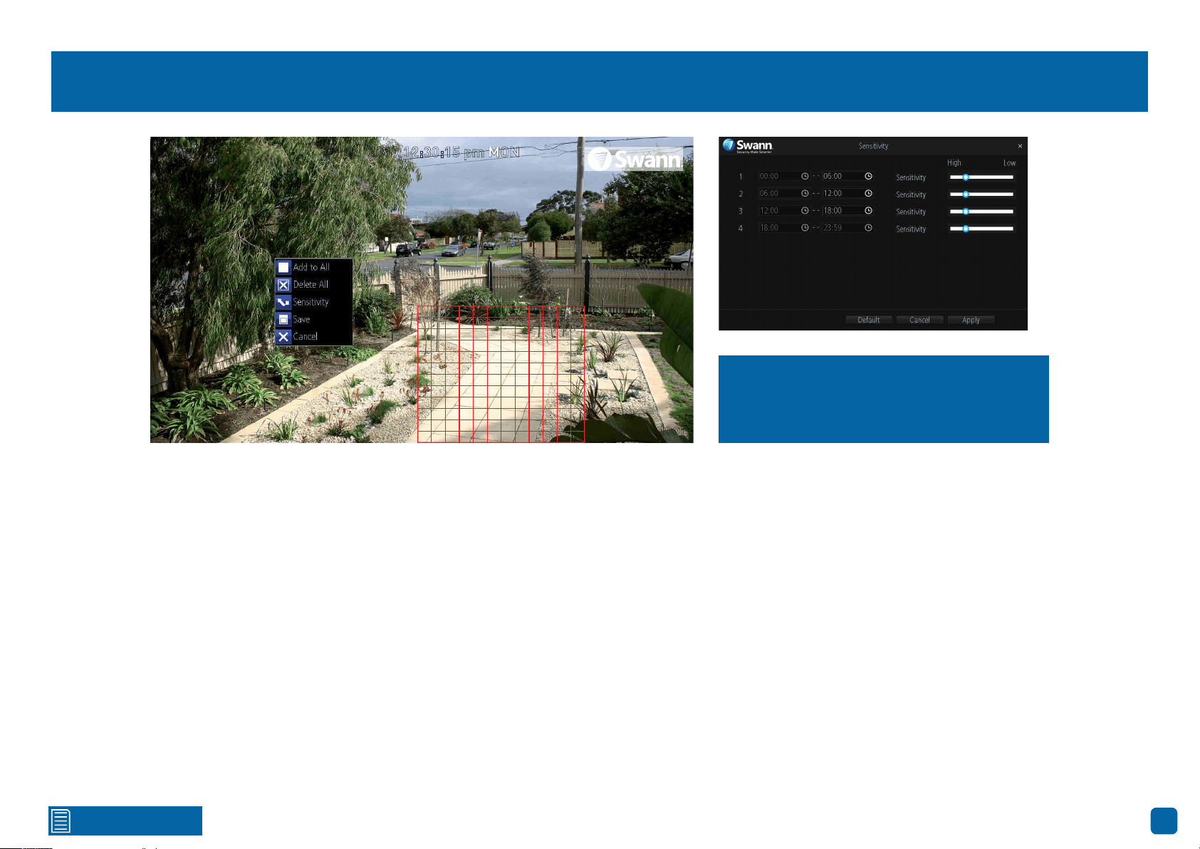
Motion Detection Setup
The entire view of the camera is enabled for motion detection, however this
can be changed if you wish.
In the example provided, a motion detection area has been created for the
front yard but excludes objects such as trees as well as cars and pedestrians
adjacent to the front yard of the house. Anyone who walks along the path via
the front entrance and approaches the front door will be detected.
To create a new motion detection area, please do the following:
1.
Right-click the mouse to access the sub-menu then click “Delete All”.
2. To create a new motion detection area, press and hold the left mouse but-
ton, click and drag to select the area that you want to create then release the
mouse. Multiple areas can be created. The same action also applies if you
want to delete an area that has been created.
3. Right-click the mouse to access the sub-menu then click “Sensitivity” to
adjust the sensitivity level (see above right) if required. When finished click
“Apply” then right-click to exit.
4. Right-click the mouse to access the sub-menu then click “Save” to save
any changes made. To revert back to default settings click “Add to All” or click
“Cancel” to exit.
08/04/2019 12:30:15 pm MON
Front door
Use the Sensitivity function to change the
motion sensitivity for each time period.
Move the slider left or right to change.
Click for contents
19
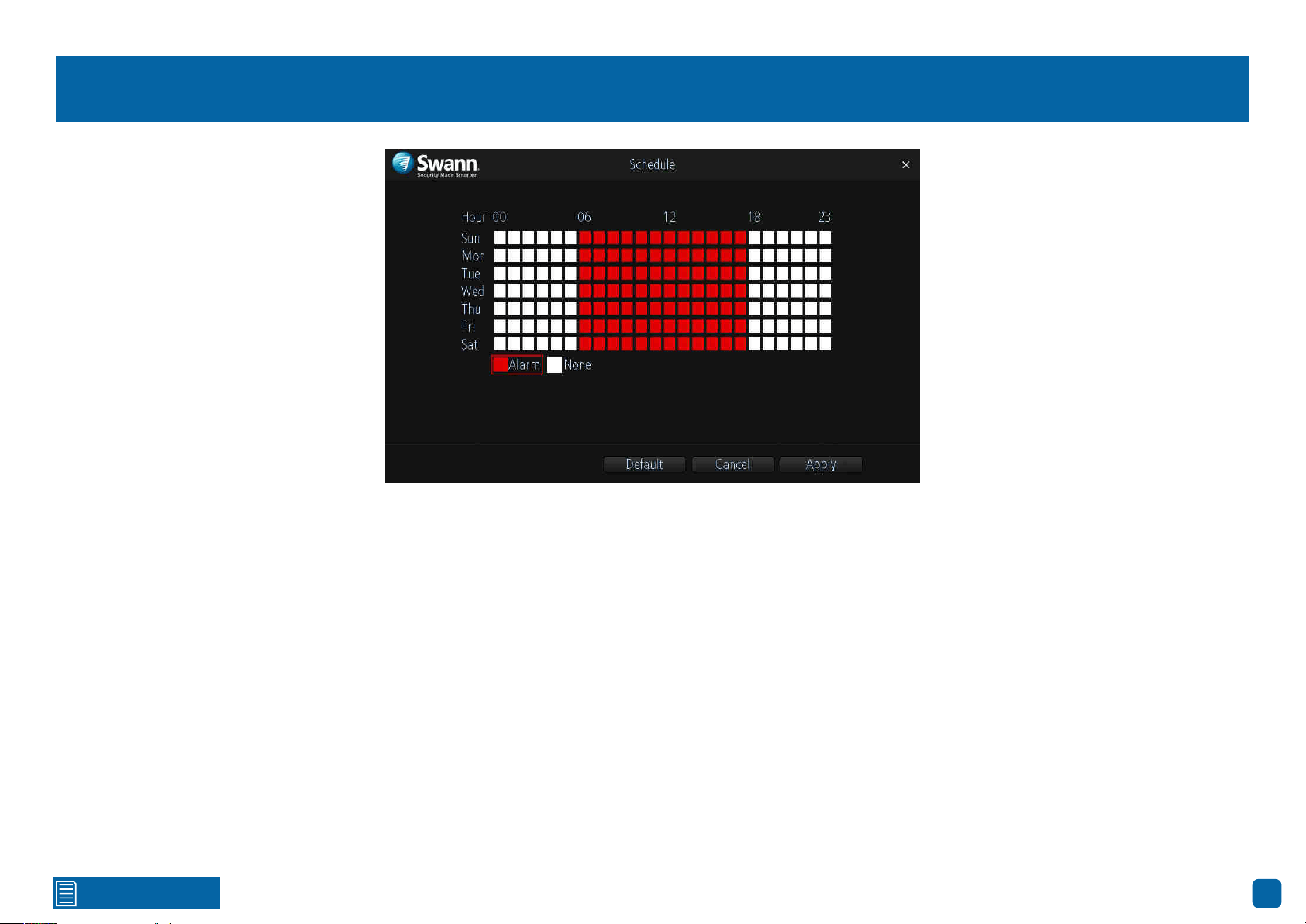
Motion: Schedule
By default, a motion detection alarm schedule has been enabled for each
camera connected, however you can change the schedule to suit your needs.
The schedule is presented as a 24-hour 7 days a week grid.
Each square represents 60 minutes. Using the mouse, click on a particular
square to change or click and drag the mouse over the squares correspond-
ing to your desired time period. The same action can also be applied if re-
cording is not required on one or more sections that have recording enabled.
In the above example, a schedule has been created for 06:00 a.m. to 06:00
p.m. Sunday to Saturday.
→ Click the “Default” button to revert back to default settings.
→ Click the “Cancel” button to exit.
→ Don’t forget to click “Apply” to save settings.

Click for contents
20
Motion Detection Tips
Placement of the cameras
1.
Place cameras so they are facing areas where people have to walk through to approach your home
regardless of where they are headed. A good idea is to place a camera overlooking your front door
to capture an image of anyone approaching it for later reference. This is great if you have parcels
delivered to your door or if the potential burglar knocks or rings the doorbell to see if anyone is home.
2. Walk around your house and assess where intruders are most likely to approach to enter, and what
path they would take. Most burglars enter the home through a front or back door, so it’s advisable
to place the cameras near those areas so that you get the best amount of detail of anyone who
approaches.
3. When installing cameras outside, it’s important to keep your front and backyard as well-lit as
possible for ideal night vision and the ability to detect motion. It’s common for intruders to enter a
home through an unlocked garage or by using a garage door opener in an unlocked car located in
the driveway. Positioning your cameras to overlook cars in the driveway and similar locations can be
very useful.
Avoiding False Triggers
1.
A tree, shrub or foliage that is blown by the wind - angle the camera so wind-blown objects are out
of the camera’s view or use the camera motion detection area settings to exclude these areas from
detection.
2. People moving along sidewalks or streets that are close to your home, aim your cameras and use
the motion detection area settings to ensure only legitimate threats are triggering events.
3. Vehicles moving in the background - angle the camera so as to avoid movement in the background
or use the motion detection area settings to stop detection of cars in the street.
4. Movement or light reflected off smooth surfaces such as glass - adjust the sensitivity level and/or
avoid pointing the camera directly at glass surfaces.
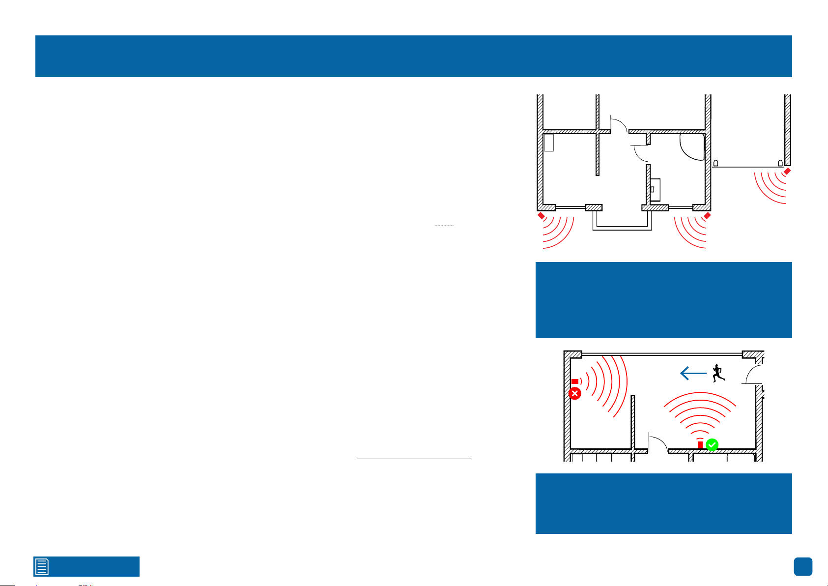
The red cameras illustrated (see above) are your
primary locations. Place your cameras close to
the front door, back door, garage entrance and
overlooking the backyard.
The blue cameras illustrated are your secondary
locations. If your NVR includes additional cam-
eras, place these at the front entrance inside the
home, the front of the house (this could overlook
the front garden or driveway), a side gate or if you
have multiple entrances to the backyard.
Click for contents
21
Thermal-Sensing Camera Tips
Your cameras have a built-in PIR (passive infrared motion detector) sensor. This means they can
sense movement of warm objects including people, cars and animals. The advantage over cameras
that don’t have a PIR sensor, is they are very resistant to false triggers from changes in the image.
→ PIR sensors work best when an intruder walks parallel or is passing across their “field of view”
as opposed to walking directly at them. For example, in a hallway or path around the house you
tend to walk parallel to the walls, not directly toward them. Position your cameras so that anyone
approaching your home will cross the camera’s view and trigger an event.
→ For a recording to occur, the PIR must sense a warm object moving in front of it and the camera’s
image sensor must detect movement in the image. If either of these triggers has not occurred,
no video will be recorded.
→ When the PIR is triggered, the PIR icon (red box) will flash on-screen. If PIR and motion are trig-
gered, the “running man” icon will be shown on-screen indicating that an event has occurred and
that a recording is happening.
→ The PIR can detect objects outside of the camera’s field of view, so not everything that triggers the
sensor will be visible on your camera.
→ The PIR can reliably detect movement up to 30ft/9m, movement beyond this range may or may
not be detected.
→ Be aware that sudden changes in temperature of paths, roads, for example, can cause some mi-
nor false alerts to occur when there is also movement in the image such as trees and shadows.
→ If some false triggering is occurring, use the motion area setup to remove moving objects from
being detected, and to further refine your alerts (see page 18 - Motion Detection Setup).
→ When used indoors, keep the cameras away from heating vents, heaters and other heat sources
as they can trigger the PIR. However if there is no movement in the image, a false alert is unlikely.
When installing cameras outside, mount them
where intruders are most likely to enter (front &
back doors, garage entrance). Angle the camer-
as so the intruder walks parallel to the sensor.
PIR sensors work best when an intruder walks
parallel or is passing across their “field of view”
as opposed to walking directly at them.
Click for contents
22
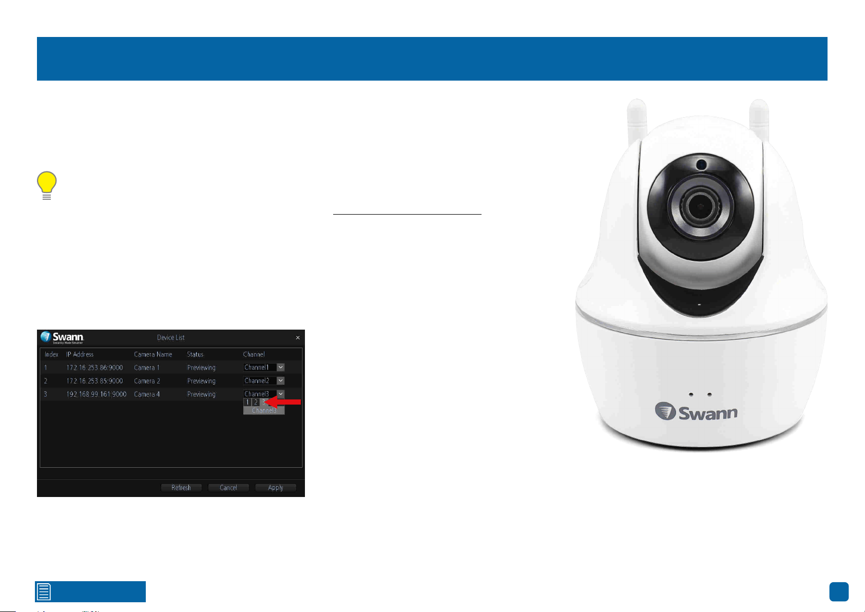
Configuring your Swann PT Cam (SWWHD-PTCAM)
If you have previously purchased a Swann PT Cam (also known as Wi-Fi Pan & Tilt Security Camera) or
looking to add an additional camera to your NVR, the Swann PT Cam is fully compatible with your NVR.
You can use the PTZ controls to pan and tilt the camera. Multiple preset positions can also be created,
which can be recalled to focus the camera’s view to a different position.
Please note: Your NVR supports a maximum of four cameras that can be configured and displayed.
If you have the maximum amount of cameras configured and would like to use the PT Cam, you
need to disconnect one of the cameras first (see page 14 - Channel: Managing Cameras).
The following instructions are dependent on which mode your NVR is running in, AP or Station mode.
AP Mode: If your NVR and PT Cam are physically connected to your Wi-Fi access point using the supplied
Ethernet cables, your NVR will detect the PT Cam automatically and will appear in Live View mode. If you
don’t see the PT Cam in Live View mode, please do the following:
1. Right-click the mouse in Live View mode to access the Menu Bar then click the “Channel” button.
2. Assign the PT Cam a channel number (as shown above) then click “Apply”. After a short moment, the
PT Cam will appear in Live View mode. Close the Device List when finished.
(continued on next page)
Click for contents
23
Configuring your Swann PT Cam (SWWHD-PTCAM)
Station Mode: If the PT Cam is wirelessly connected to your Wi-Fi access point and your NVR is running in AP mode, you need to change this to Station mode.
Station mode allows wireless communication from your NVR to the Wi-Fi access point. Please do the following:
1. Right-click the mouse in Live View mode to access the Menu Bar, click the “Menu” button, click “Network” then click “Wi-Fi Setting”.
2. For Wi-Fi Mode, click the drop down menu then select “Station”. After a short moment, a list of Wi-Fi access points that your NVR detects, will be shown.
Select your Wi-Fi access point then click the next button (circle & triangle).
4. Input the password for your Wi-Fi access point then click the next button (circle & triangle). Make sure the password is correct before proceeding.
5. A message will appear on-screen stating that all cameras must be connected before proceeding. Click the next button (circle & triangle).
6. The cameras connected to your NVR will be displayed. A tick icon will appear in each checkbox.
7. After a brief moment your NVR will reboot then you will see your cameras, including the PT Cam, in Live View mode. You can now disconnect the Ethernet
cable connected to your NVR’s Ethernet port.
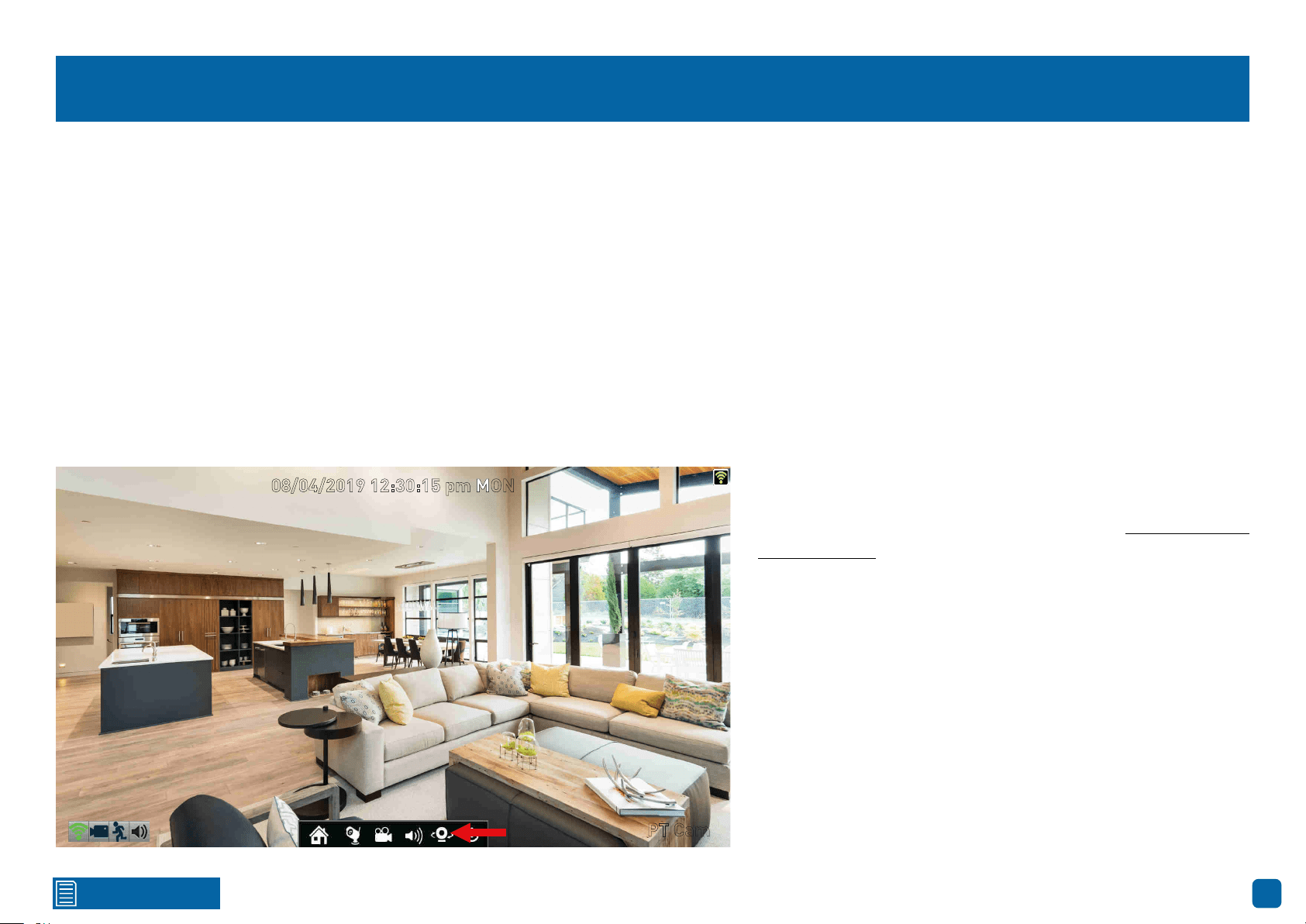
08/04/2019 12:30:15 pm MON
PT Cam
Now that your NVR has detected the PT Cam, the “PTZ” button
will appear on the Menu Bar (as shown on the left). Click this
button to access the PTZ controls (see page 24 - Controlling your
Swann PT Cam).
Click for contents
24
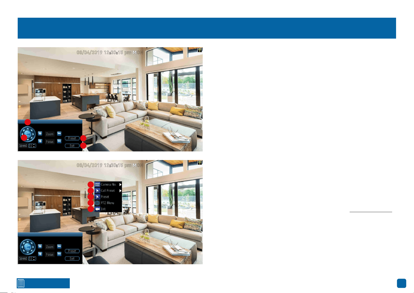
Controlling your Swann PT Cam
To control your Swann PT Cam, in Live View mode right-click the mouse to
access the Menu Bar then click the “PTZ” button. The channel will go full
screen and the PTZ controls will be visible (as shown on the left).
1. Click the directional buttons to move the camera in the direction selected.
2. Click this button to pan the camera continuously for 60 seconds.
3. Click this to access the Preset menu.
4. Click this to exit. You will be taken back to the default Live View mode.
To access the PTZ menu, right-click the mouse (as shown bottom left).
5. If you have multiple Swann PT Cams configured, click this to select a dif-
ferent channel.
6. Click this to select a different Preset position.
7. Click this to access the Preset menu.
8. Click this to hide the PTZ controls. Right-click the mouse and click this
again to return.
9. Click this to exit. You will be taken back to the default Live View mode.
The Speed, Zoom and Focus controls are not used.
For instructions on how to create a Preset (see page 25 - Creating a Preset).
08/04/2019 12:30:15 pm MON
PT Cam
08/04/2019 12:30:15 pm MON
PT Cam
1
2
3
4
1
2
3
44
5
6
7
8
9
1
2
3
4
5
6
7
8
9
Click for contents
25
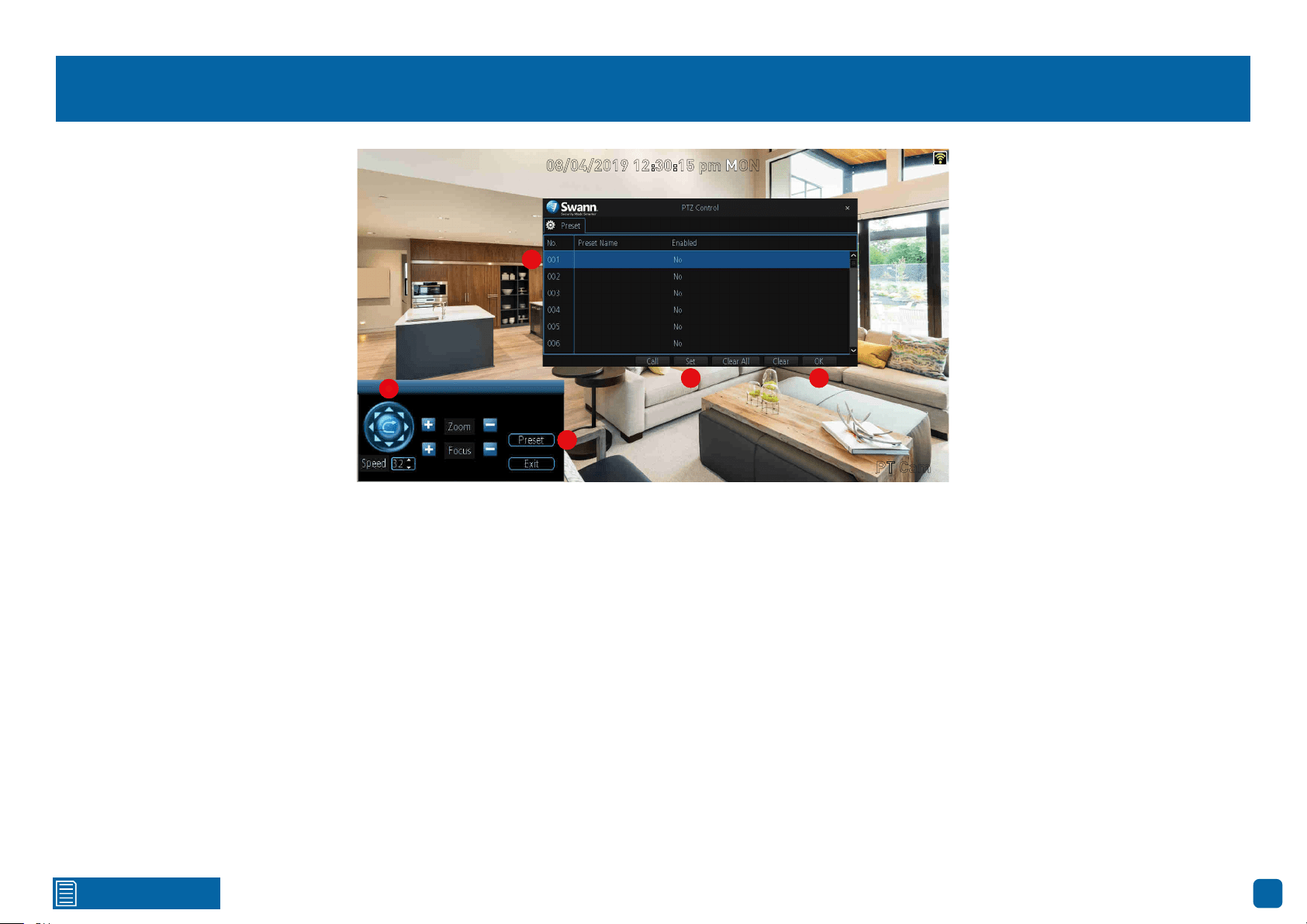
Creating a Preset
1. Use the PTZ controls to move the camera to the desired focal position.
2. Click the “Preset” button to access the Preset menu.
3. Click the first Preset slot available. Click the space under “Preset Name”
to give the slot a relevant name.
4. Click the “Set” button to save (this will change from No to Yes).
5. Click “OK” to exit.
Repeat the above steps to create multiple Preset positions. Make sure you
change the Preset slot for each Preset that you want to create. Up to 128 dif-
ferent Preset positions can be created.
Call: Select a saved Preset slot then click this to move the camera to the
Preset position.
Clear All: Click this to clear all Preset slots.
Clear: Select a saved Preset slot then click this to clear.
08/04/2019 12:30:15 pm MON
PT Cam
1
2
3
4 5
1
2
3
4 5
26
Click for contents
Recording Configuration
The recording schedule is accessible from
the “Recording” menu. From here you can
change the schedule for each camera con-
nected. By default, a motion detection alarm
schedule has been enabled for each camera.
However, you can change the schedule ac-
cording to what fits in with your needs.
Click for contents
27
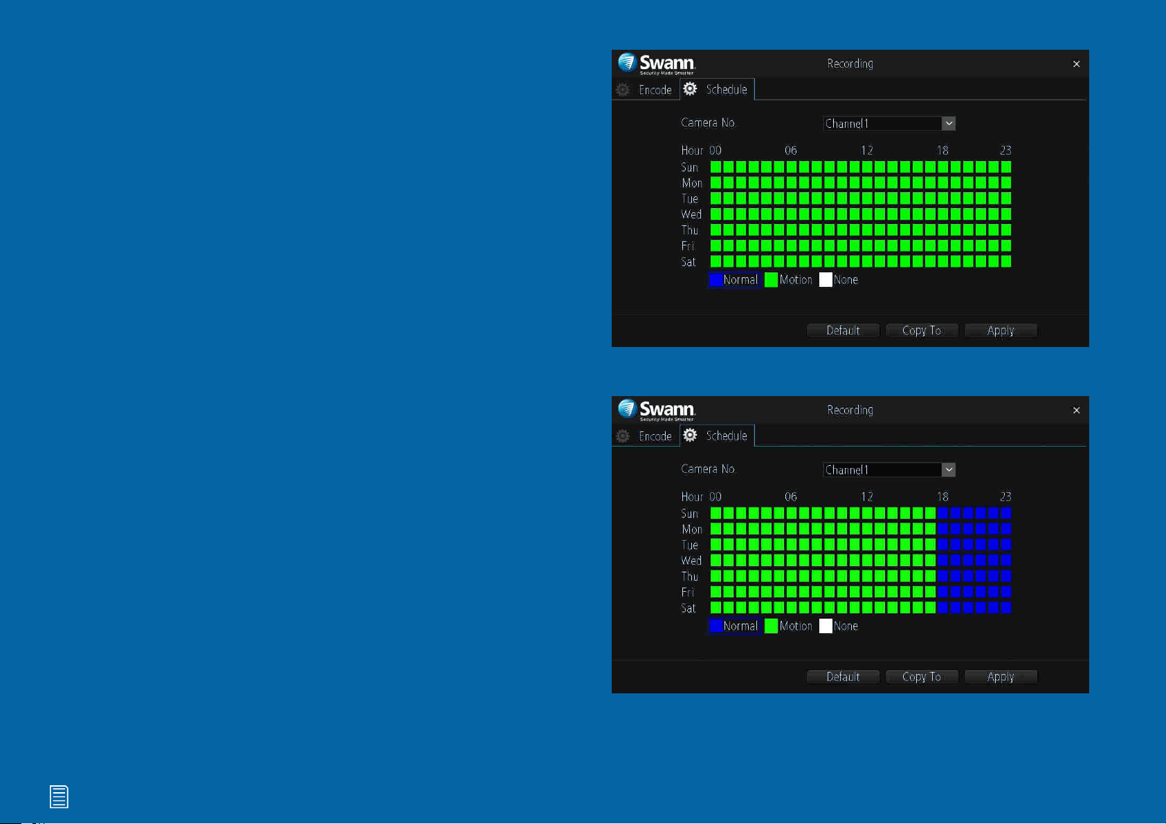
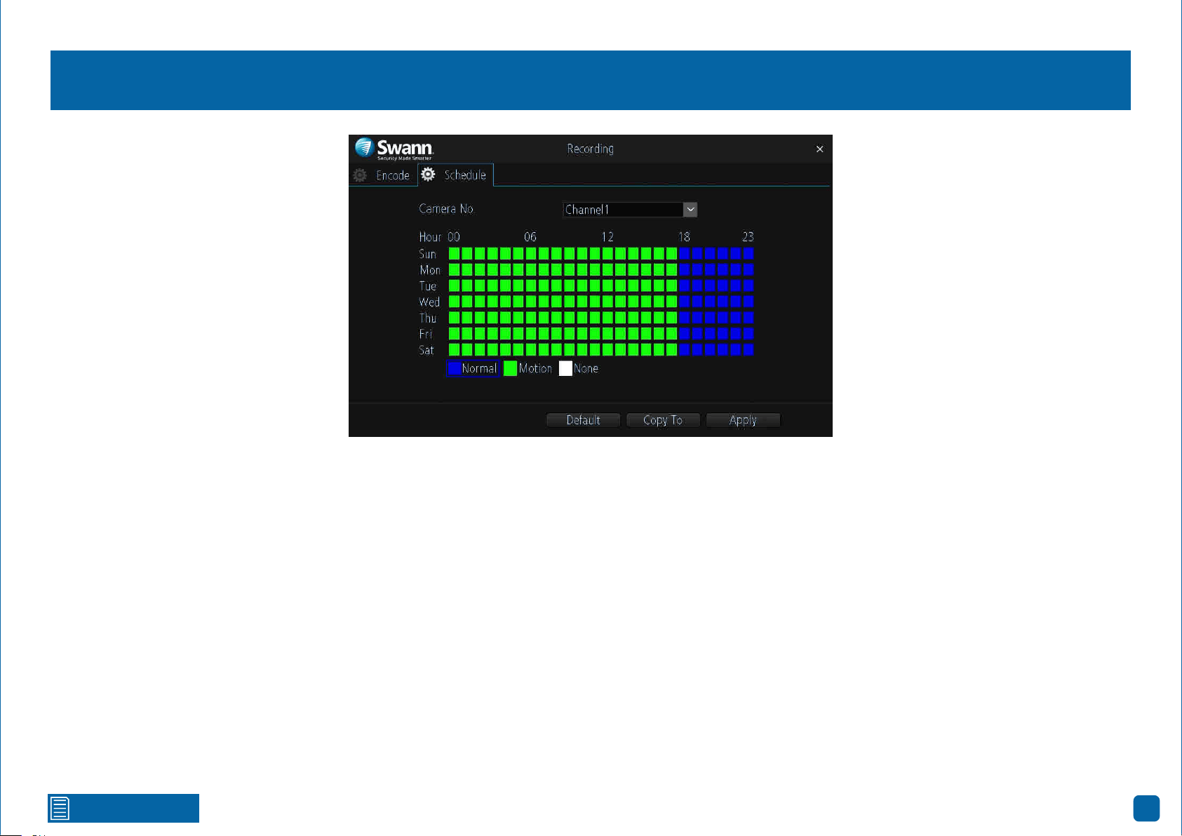
Recording: Schedule
By default, a motion detection recording schedule has been enabled for each
camera connected, however you can change the schedule to suit your needs.
The schedule is presented as a 24-hour 7 days a week grid and is color coded
to represent the event type.
Camera No.: Select a camera that you would like to configure.
Normal: Your NVR will constantly record for a set period of time (this option
is not visible when recording to a MicroSD card).
Motion: Your NVR will only record when motion has been detected from one
or more cameras.
None: As the name describes, your NVR will not record anything.
In the above example, a Motion recording schedule has been created for
12:00 a.m. to 06:00 p.m. and a Normal recording schedule for 06:00 p.m. to
12:00 a.m. Sunday to Saturday. Using the mouse, select the desired record-
ing mode (Normal, Motion or None) then click and drag the mouse over the
squares corresponding to your desired time period.
→ Click the “Default” button to revert back to default settings.
→ Use the “Copy to” button to apply all settings to the other cameras.
→ Don’t forget to click “Apply” to save settings.
28
Click for contents
Playback & Backup
The Search function gives you the ability to
search and play previously recorded videos
that are stored on your NVR’s storage device.
Each camera is presented as a 24 hour grid
and is colour coded to represent the event
type. A monthly calendar is also visible alert-
ing you on which days have recordings availa-
ble. The Backup function gives you the ability
to save important events to a USB flash drive.

Click for contents
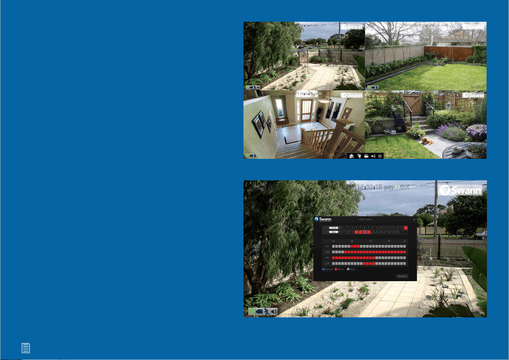
29
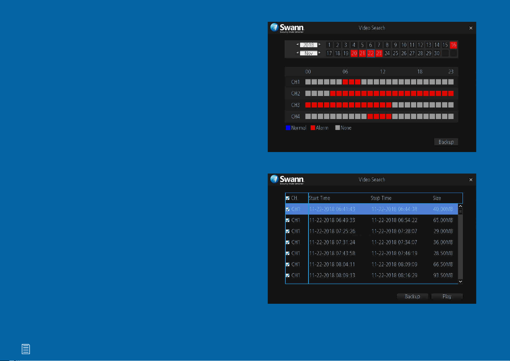
Search: Video Search
Each camera is presented as a 24 hour grid and is colour coded to represent
the event type (Normal or Alarm). A calendar is also visible alerting you on
which days have recordings available (dates in red have recordings available).
1. Select the year and month that you would like to search for then select a
date to display the recordings available.
2. Click on a particular event to play back video (see page 30 - Playback In-
terface).
3. Click the “Backup” button to save important events to a USB flash drive.
After clicking the button, you will see a list of videos that match the date that
has been selected (see page 32 - Search: Backup).
Please note: When playing back events, your NVR will continue to mon-
itor and record as normal, therefore playback performance may be sac-
rificed.
1
2
1
2
3
1
2
3
Click for contents
30
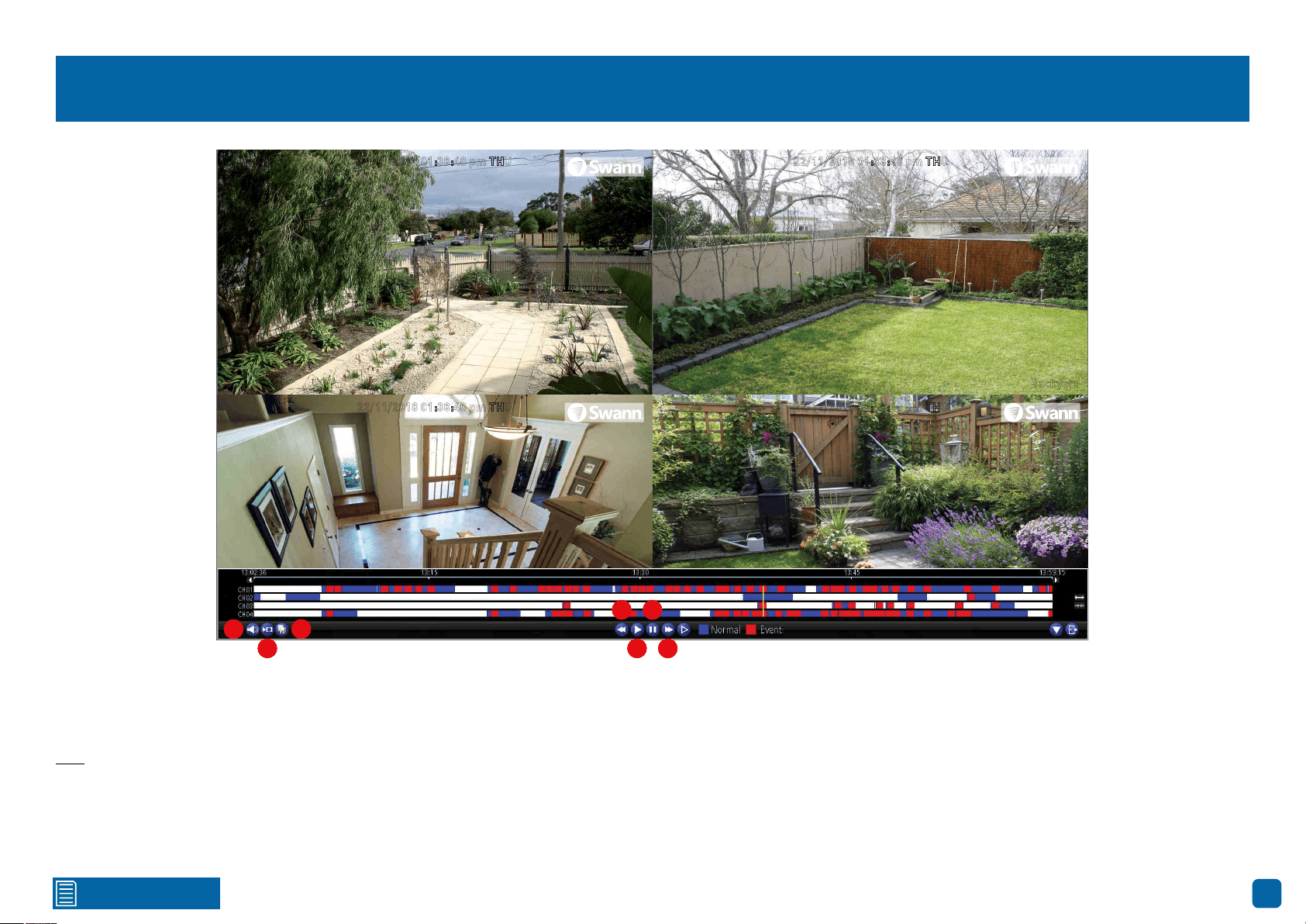
Playback Interface
1. Click this button to mute or unmute the audio.
2. Click this button to make one or more cuts in your video which you can then
export to a USB flash drive. When a video is playing, press this button, press
and hold the mouse button while dragging along the timeline to set the mark
in point then release the mouse button to set the mark out point. You will see
a scissor icon above the timeline indicating the two points that have been
created. Multiple mark in and out points can be created.
3. Click this to save your mark in and mark out points to a USB flash drive.
4. Click this to rewind playback. Subsequent presses will increase the speed.
5. Click this to play video.
6. Click this to pause playback. Subsequent presses will move a single frame
forward in the video.
7. Click this to speed up playback. Subsequent presses will increase the
speed.
(continued on next page)
22/11/2018 01:38:40 pm THU
Backyard
22/11/2018 01:38:40 pm THU
Front door
22/11/2018 01:38:40 pm THU
Staircase
22/11/2018 01:38:40 pm THU
Side gate
1
2
3
4
5
6
7
1
2
3
4
5
6
7
1
2
3
4
5
6
7
Click for contents
31
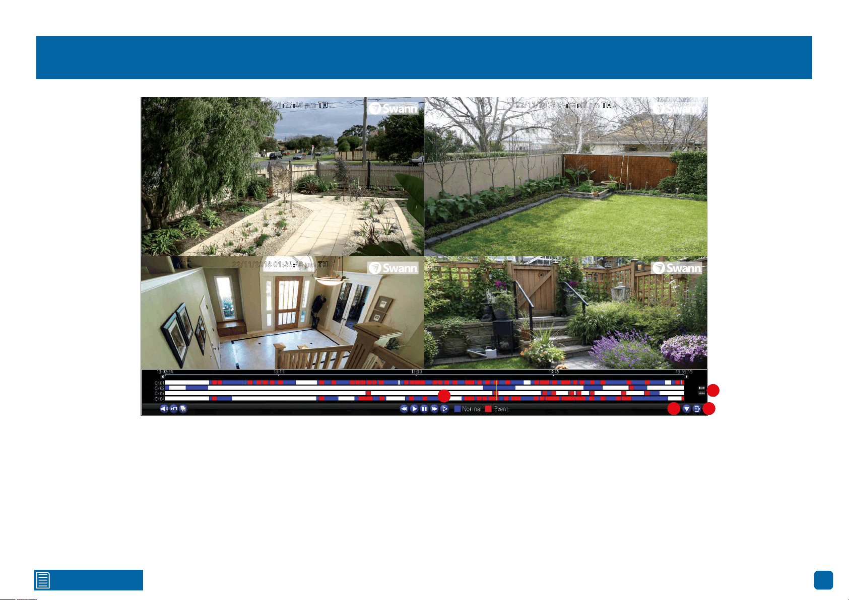
Playback Interface
8. Click this to reduce playback speed. Subsequent presses will further re-
duce the speed. Click the “Play” button to resume normal playback.
9. Click this to hide the playback interface to maximise the viewing area (you
can also do this by right-clicking the mouse then clicking “Console”).
10. Click this to exit.
11. Click these to zoom in and out of the timeline for precise control.
22/11/2018 01:38:40 pm THU
Backyard
22/11/2018 01:38:40 pm THU
Front door
22/11/2018 01:38:40 pm THU
Staircase
22/11/2018 01:38:40 pm THU
Side gate
9 10
11
88
9 10
11
8
9 10
11
Click for contents
32
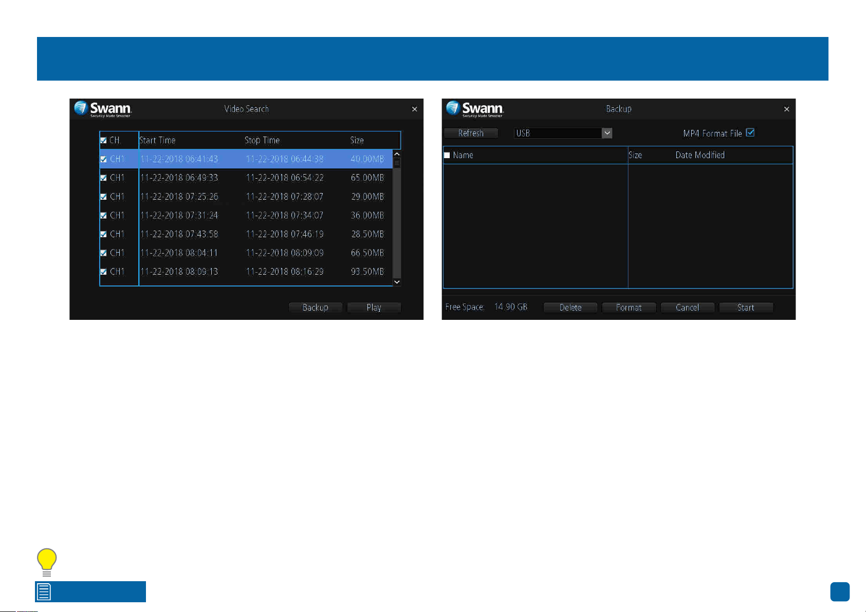
Search: Backup
1. By default, each video listed has been selected for backup. If this isn’t re-
quired, click the checkbox next to “CH.” to deselect all videos then click the
checkbox next to the video that you want to backup.
2. To check that the video you’ve selected is the one that you want to backup,
click the “Play” button.
3. Before proceeding, connect a USB flash drive to the USB port located at
the rear of your NVR.
4. Wait a short moment then click “Backup”.
5. Select the location that you want to save to then click “Start”. A progress
bar will be displayed on-screen. You also have the option of deleting files and
to format the storage device. When finished, right-click the mouse to exit.
Please note: Depending on the number of files that have been selected,
the backup process can be time consuming, therefore we don’t recom-
mend that you backup the entire storage device. Only backup recordings that
are required.
33
Click for contents
System Configuration
The options available here give you complete
control on how your NVR is configured and
how it operates. Some of the options such as
screen resolution, time zone, email configu-
ration, password creation and Daylight Saving
Time are configured during the Wizard. You
can also perform a firmware upgrade when
available.

Click for contents
34
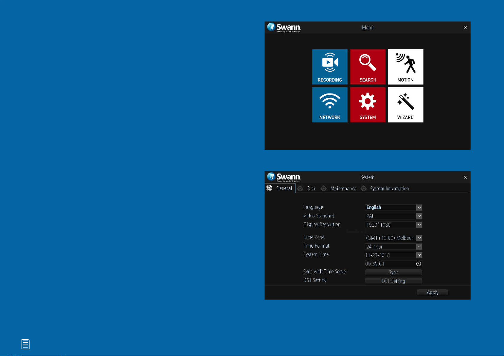
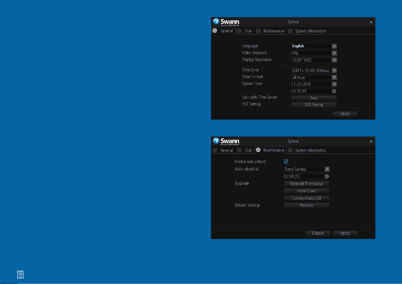
System: General
Language: Select a language you would like the system menus to be dis-
played in. Multiple languages are available.
Video Standard: Select the correct video standard for your country. USA and
Canada are NTSC. UK, Australia and New Zealand are PAL.
Display Resolution: Select a display resolution that is suitable for your TV.
1920 x 1080 will suit most TVs.
Time Zone: Select a time zone relevant to your region or city.
Time Format: Click the drop down menu to select the preferred time format.
System Time: Select the correct date and time. The date is displayed as
month, day and year.
Sync with Time Server: Click to automatically synchronize your NVR’s inter-
nal clock with a time server. A message will appear on-screen stating sync
time has been successful. Click “OK” to continue.
DST Setting: Click this to configure your NVR to automatically adjust its time
for Daylight Saving in your time zone (see page 35 - Daylight Saving).
→ Don’t forget to click “Apply” to save settings.

Click for contents
35
Daylight Saving
Enable DST: Click the checkbox to enable.
Offset: Select the time that Daylight Saving has increased by in your time
zone. Adjust accordingly.
Mode: Select to enable Daylight Saving by week or by date.
Start Time/End Time: Set when Daylight Saving starts and ends, for exam-
ple 2 a.m. on the first Sunday of a particular month or on a particular date.
Adjust accordingly.
→ Click the “Default” button to revert back to default settings.
→ Click the “Cancel” button to exit.
→ Don’t forget to click “Apply” to save settings.
Click for contents
36
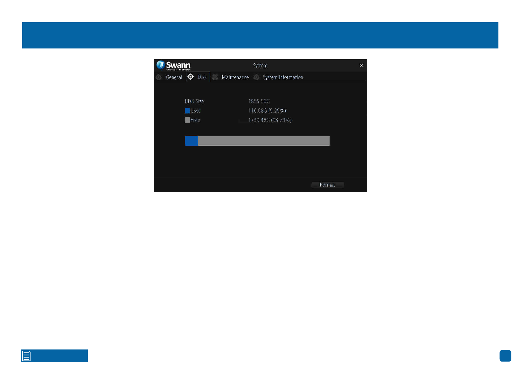
System: Disk
This function gives you the option of formatting your NVR’s storage device
(internal hard drive, USB hard drive or MicroSD card). If a new storage device
has been connected and installed, it must be formatted before use.
Format: Click this to format the storage device. A message will appear on-
screen stating that all your recordings will be deleted (If you have any re-
cordings that are required, back them up to a USB flash drive). Click “OK” to
continue. The storage device will now format which will only take a few short
moments.
Click for contents
37
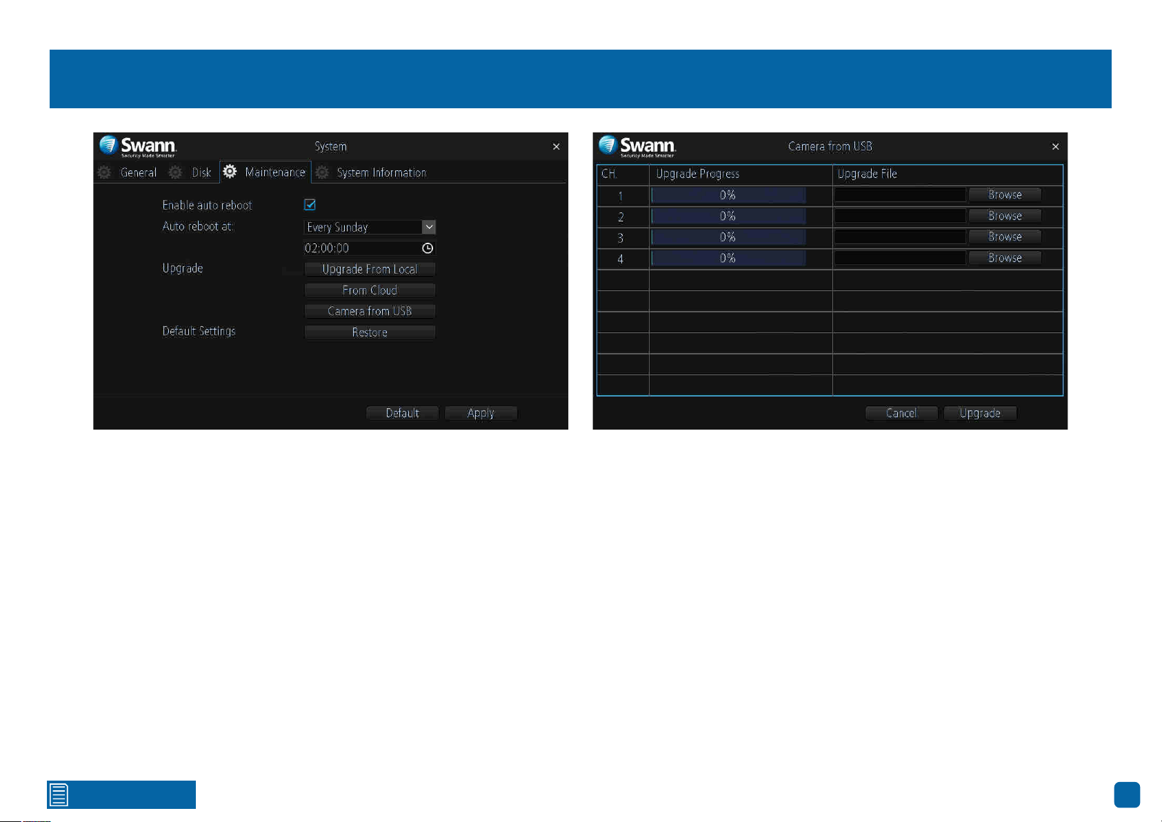
System: Maintenance
Enable auto reboot: It’s recommended to leave this enabled as it maintains
the operational integrity of your NVR.
Auto reboot at: Choose an appropriate day and time to reboot your NVR.
Upgrade From Local: Click this to upgrade the firmware via a USB flash
drive. Select the firmware file, click “Upgrade” then “OK” to confirm. When
the firmware upgrade has completed, your NVR will reboot automatically.
Upgrade From Cloud: Click this to check if an updated firmware is available
using your internet connection. A message will appear on-screen informing
you if an update is available. Click the “Upgrade” button to proceed then fol-
low the on-screen instructions.
Upgrade Camera from USB: Click this to upgrade the camera’s firmware
via a USB flash drive (see above right screenshot). To upgrade the firmware,
click “Browse”, select the firmware file then click “OK”. Repeat these steps
for each camera displayed. When finished click “Upgrade”. Each camera will
restart when the upgrade has completed.
Default Settings: Click this to restore factory default settings. All recordings
on the storage device will remain.
→ Click the “Default” button to revert back to default settings.
→ Don’t forget to click “Apply” to save settings.
Click for contents
38
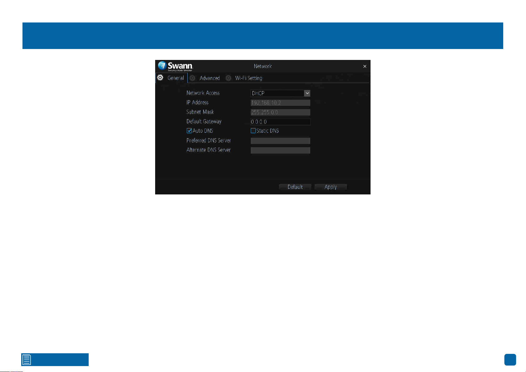
Network: General
As SwannLink Peer-to-Peer technology is utilised to communicate with your
network and mobile device, configuration of the network settings is not re-
quired. If you have networking expertise and require specific settings for your
network, you do have the ability to change them.
Network Access: You can select between two different network types that
your NVR can be connected to. The two types are:
DHCP (Dynamic Host Configuration Protocol): Your router will automatical-
ly assign an IP address to each device connected to your network. This is
enabled by default.
Static: All devices on your network have their IP address manually defined.
IP Address: Each device on your network must have a unique IP address. A
typical address might be “192.168.1.24” or something similar.
Subnet Mask: This allows the flow of network traffic between hosts to be
segregated based on a network configuration. A typical address might be
“255.255.255.0” or something similar.
Default Gateway: This allows your NVR to connect to the internet. This is
typically the same IP address as your modem or router.
Auto DNS/Static DNS: Select how would like to define your DNS servers. It’s
recommended to leave this on auto.
→ Click the “Default” button to revert back to default settings.
→ Don’t forget to click “Apply” to save settings.
Click for contents
39
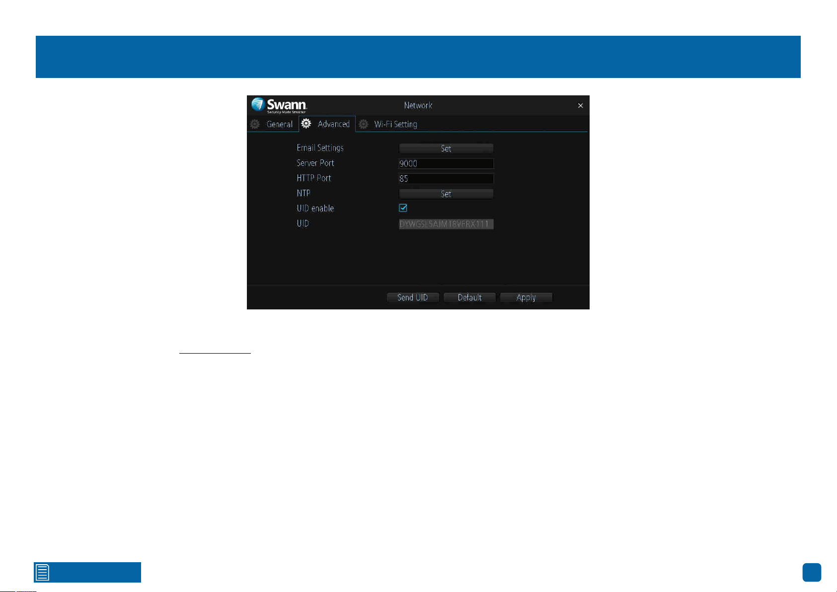
Network: Advanced
Email Settings: Click the “Set” button if any changes are required to your
email account (see page 40 - Email Settings).
Server Port: This port number is used by your NVR to send information
through. The default number will work in most situations.
HTTP Port: This port number is used to log into your NVR from a remote
location. The default number will work in most situations.
NTP (Network Time Protocol): This function allows your NVR to automat-
ically sync its clock with a time server. This gives it the ability to constantly
have an accurate time setting (your NVR will periodically sync automatically).
UID enable: This is part of SwannLink and is enabled by default.
UID: This is your NVR’s unique identification code. Click “Send UID” to send
this to your email address.
→ Click the “Default” button to revert back to default settings.
→ Don’t forget to click “Apply” to save settings.
Click for contents
40
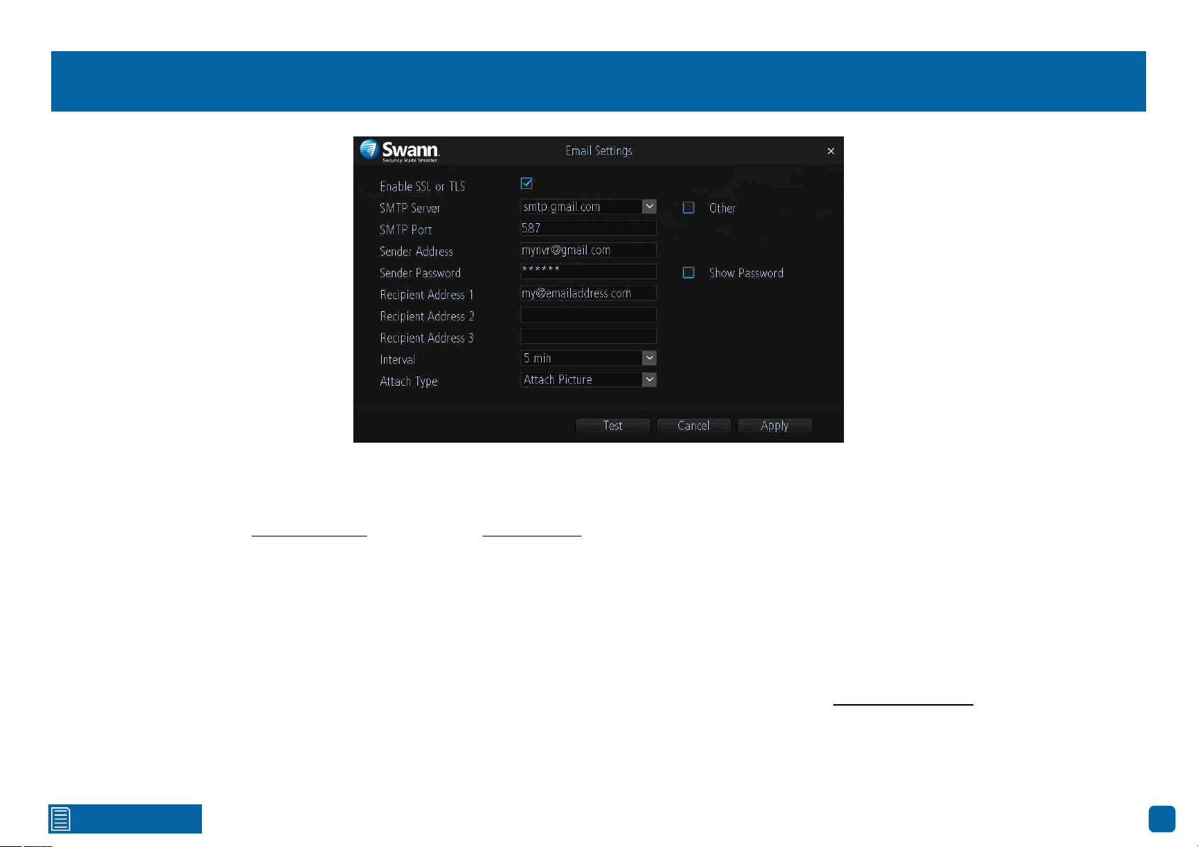
Email Settings
Enable SSL or TLS: This is enabled by default and is required by most email
providers.
SMTP Server: Gmail select smtp.gmail.com. Outlook select smtp.live.com.
Click the “Other” checkbox if you would like to use your own email server.
SMTP Port: Change this to 587 for both Gmail and Outlook.com.
Sender Address: Input the email address for the account you created.
Sender Password: Input the email password for the account you created.
Click the “Show Password” checkbox to show your password.
Recipient Address: Input an email address that you want to send email alerts
to. You can input up to three different email addresses.
Interval: This is the length of time that must elapse after your NVR sends an
email alert before it will send another. Adjust accordingly.
Attach Type: Select the attachment type (picture or video) that you want to
receive with your email alerts.
Test: Click to verify the information you entered is correct then click “OK”.
Email not working? Please try the following:
1.
Check that your email user name and password are correct.
2. Located at the back of your NVR, you should see one or two flashing LEDs
(above the Ethernet port). If you don’t see this, disconnect then reconnect the
Ethernet cable or try a different port on your router.
3. Search “less secure apps” at support.swann.com.
→ Click the “Cancel” button to exit.
→ Don’t forget to click “Apply” to save settings.
Click for contents
41
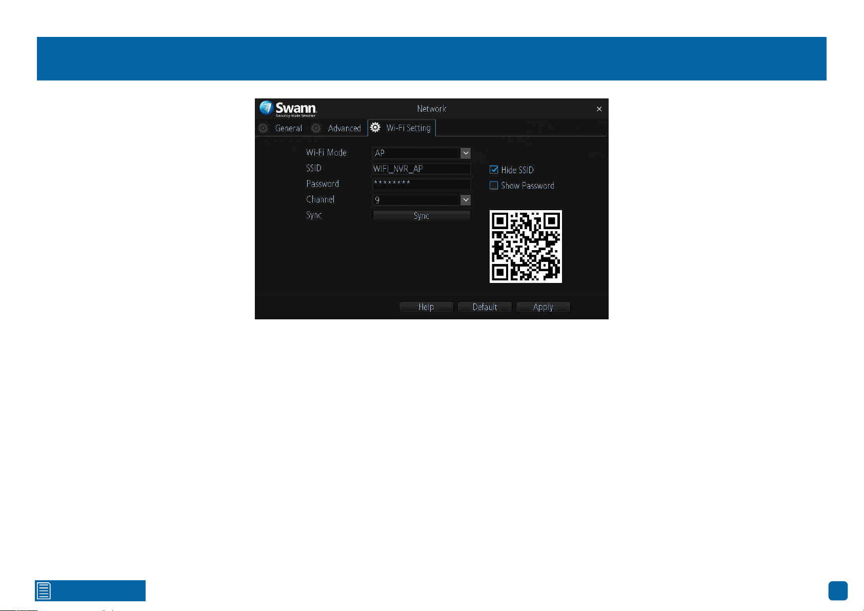
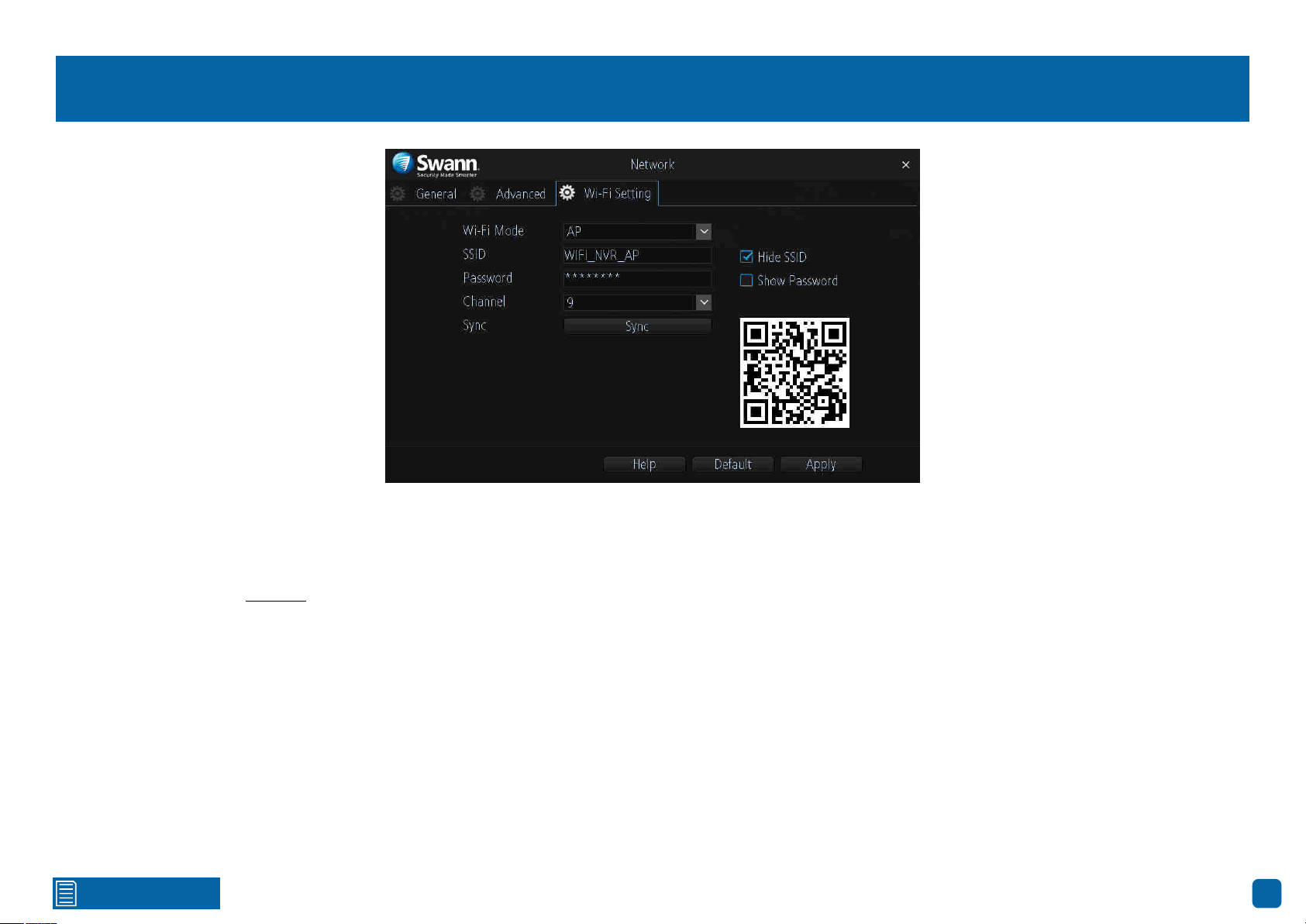
Network: Wi-Fi Setting (AP Mode)
Wi-Fi Mode: The default mode of operation for your NVR is AP mode. The
cameras will connect (wirelessly) to your NVR and the NVR must be physi-
cally connected to your router to gain internet access. For more information
about Station mode (see page 42).
SSID: Just like your Wi-Fi access point, this is the network name of your NVR.
You can leave the default name or you can change it if required.
Hide SSID: We recommend that you leave this enabled. This ensures that no
other Wi-Fi enabled devices will see your device as a Wi-Fi access point.
Password: You can leave the default Wi-Fi password or you can change it if
required.
Show Password: Click the checkbox to display the Wi-Fi password.
Channel: All Wi-Fi devices communicate over specific wireless channels. If
you are experiencing an intermittent dropout with your cameras or slow per-
formance overall, click the drop down menu and change the channel num-
ber. If you have an Android mobile device, you can use a Wi-Fi analyzing app
to display the channels used for neighbouring Wi-Fi networks. Search for
“Wifi Analyzer” in your app store (unfortunately there isn’t an equivalent app
for iOS mobile devices).
Sync: If any settings have been changed, click this button to sync changes to
your cameras. Do not exit until this is done.
→ Click the “Help” button for instructions on how to sync Wi-Fi settings to
your cameras.
→ Click the “Default” button to revert back to default settings.
→ Don’t forget to click “Apply” to save settings.

Click for contents
42
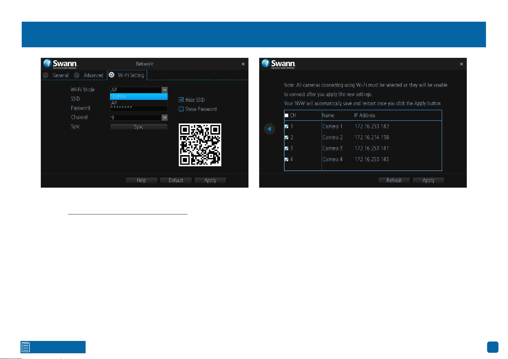
Network: Wi-Fi Setting (Station Mode)
Station mode allows wireless communication from your NVR to the router
to gain internet access. This gives you the flexibility of placing your NVR in a
different location, without having to be physically connected to your router.
In Station mode your cameras also connect to your router directly via Wi-Fi
rather than connect to your NVR, so please take the distance between your
cameras and your router into consideration when using this mode.
As mentioned in the on-screen message, make sure each camera has suc-
cessfully connected with your NVR before changing modes. This is very im-
portant as your NVR will instruct the cameras as to which mode has been
selected and will send the connection information to them over Wi-Fi. If you
see all four cameras in Live View mode, you’re good to go.
Wi-Fi Mode: Click the drop down menu, select “Station” then do the follow-
ing:
1. After a short moment, a list of Wi-Fi access points that your NVR detects,
will be shown. Select your Wi-Fi access point then click the next button (circle
& triangle).
2. Input the password for your Wi-Fi access point then click the next button
(circle & triangle). Make sure the password is correct before proceeding.
3. A message will appear on-screen stating that all cameras must be con-
nected before proceeding. Click the next button (circle & triangle).
4. The cameras connected to your NVR will be displayed. A tick icon will ap-
pear in each checkbox.
5. After a brief moment your NVR will reboot then you will see your cameras
in Live View mode. You can now disconnect the Ethernet cable connected to
your NVR’s Ethernet port.

Click for contents
43
System: System Information
This tab displays technical information about your NVR. If you call our help-
desk for assistance, our staff may ask you to access this tab to assist them in
solving any technical issues that you may be having.
Device Name: Click the dialogue box to rename your NVR (if required).
→ Don’t forget to click “Apply” to save settings.
44
Click for contents
AlwaysSafe
With the AlwaysSafe app, you can turn your
mobile device into a monitoring centre for
your NVR. Have the peace of mind that you
can monitor your home at any time from
any place. With SwannLink Peer-to-Peer,
connecting your mobile device to your NVR is
so easy - there’s no need to fiddle around with
complicated network configurations.
22/10/2018 12:30:15 MON
Front door
22/10/2018 12:30:15 MON
Backyard
22/10/2018 12:30:15 MON
Staircase
22/10/2018 12:30:15 MON
Side gate
Click for contents
45
22/10/2018 12:30:15 MON
Front door
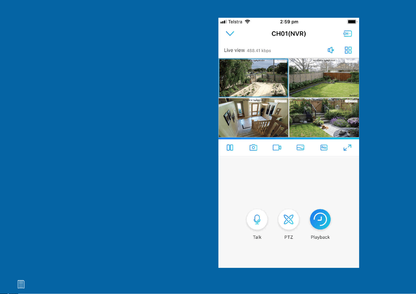
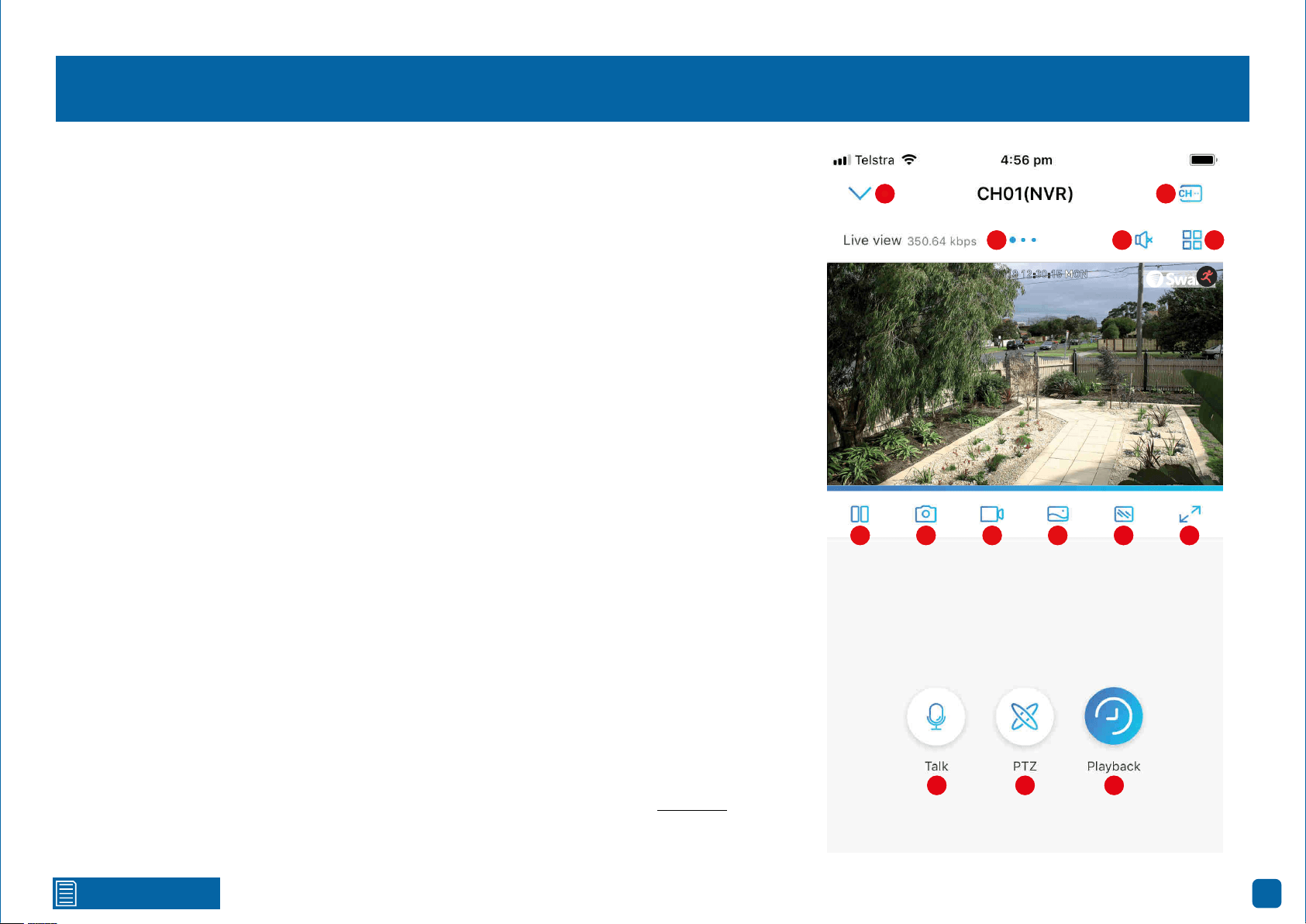
Live View
When viewing a single camera, double tap the camera to view multiple cameras at the same time.
1. Tap to return to the “Devices” screen.
2. When viewing a single camera, the large blue dot shows which camera you are viewing. Swipe
the screen left or right to change.
3. Tap to hear or mute the audio.
4. Tap this then tap the cameras to be displayed. When finished tap “Done” to return.
5. Tap to select a single camera or a multi camera display.
6. Tap to stop or start live view.
7. Tap to capture a snapshot. Snapshots are saved to the internal memory of your mobile device
(look for the AlwaysSafe folder).
8. Tap to record a video. Videos are saved to the internal memory of your mobile device (look for the
AlwaysSafe folder).
9. Tap to change from “Auto” to “Color” or “Black & White”. On Android devices, this button is in
position 10.
10. Tap to change the video stream quality between “Fluent” (smoother movement) or “Clear”
(higher quality). On Android devices, this button is in position 9.
11. Tap for a landscape (full-screen) display of the live view window. Turning your mobile device
horizontally will also do the same thing.
12. Tap to enable the talk function then tap again to start talking. As the camera’s microphone is
very sensitive, it’s normal to hear some audio feedback. Tap the button to stop talking.
13. Tap to enable pan & tilt controls (for compatible cameras only).
14. Tap to search and to play back events recorded on your NVR (see page 62 - Playback).
(continued on next page)
1
2 3
4
5
6
7
8 9
10 11
12 13 14
1
2 3
4
5
6
7 8 9 10 11
12 13 14
Click for contents
46
Live View
22/10/2018 12:30:15 MON
Front door
22/10/2018 12:30:15 MON
Backyard
Side gate
22/10/2018 12:30:15 MON
Staircase
22/10/2018 12:30:15 MON
22/10/2018 12:30:15 MON
Backyard
Side gate
22/10/2018 12:30:15 MON
Staircase
22/10/2018 12:30:15 MON
The motion icon indicates
that your NVR is detecting
motion from the camera.
1
2 3 4 5 6 7 8
This indicates that the
channel has lost the
feed from its camera.
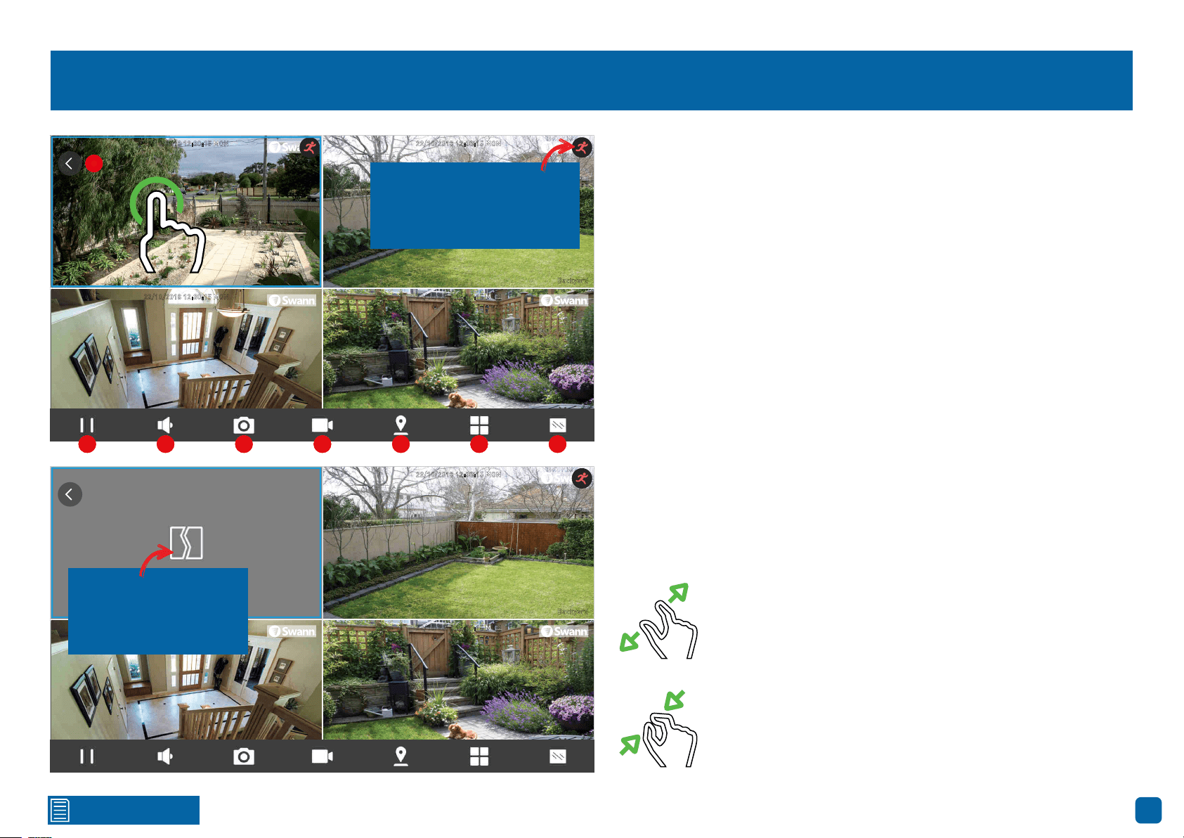
Turning your mobile device horizontally will give you a full screen display of
the Live View window. When you tap the screen, the controls will display at
the bottom. Double tap a camera to view it full screen.
When you single tap a camera, a blue square will surround it indicating
that you have selected the camera.
1. Tap for a horizontal display of the Live View window.
2. Tap to stop or start live view.
3. Tap to hear or mute the audio.
4. Tap to capture a snapshot. Snapshots are saved to the internal memory
of your mobile device (look for the AlwaysSafe folder).
5. Tap to record a video. Videos are saved to the internal memory of your
mobile device (look for the AlwaysSafe folder).
6. Tap to enable pan & tilt controls (for compatible cameras only).
7. Tap to select a single camera or a multi camera display.
8. Tap to change the video stream quality between “Fluent” (smoother
movement) or “Clear” (higher quality).
Use the spread gesture to digitally zoom into the camera’s
image. Tap and hold the zoomed image to move within it.
The spread gesture works in both horizontal and vertical
modes.
Use the pinch gesture to zoom out. The pinch gesture works
in both horizontal and vertical modes.
1
2 3 4 5 6 7 8
Click for contents
47
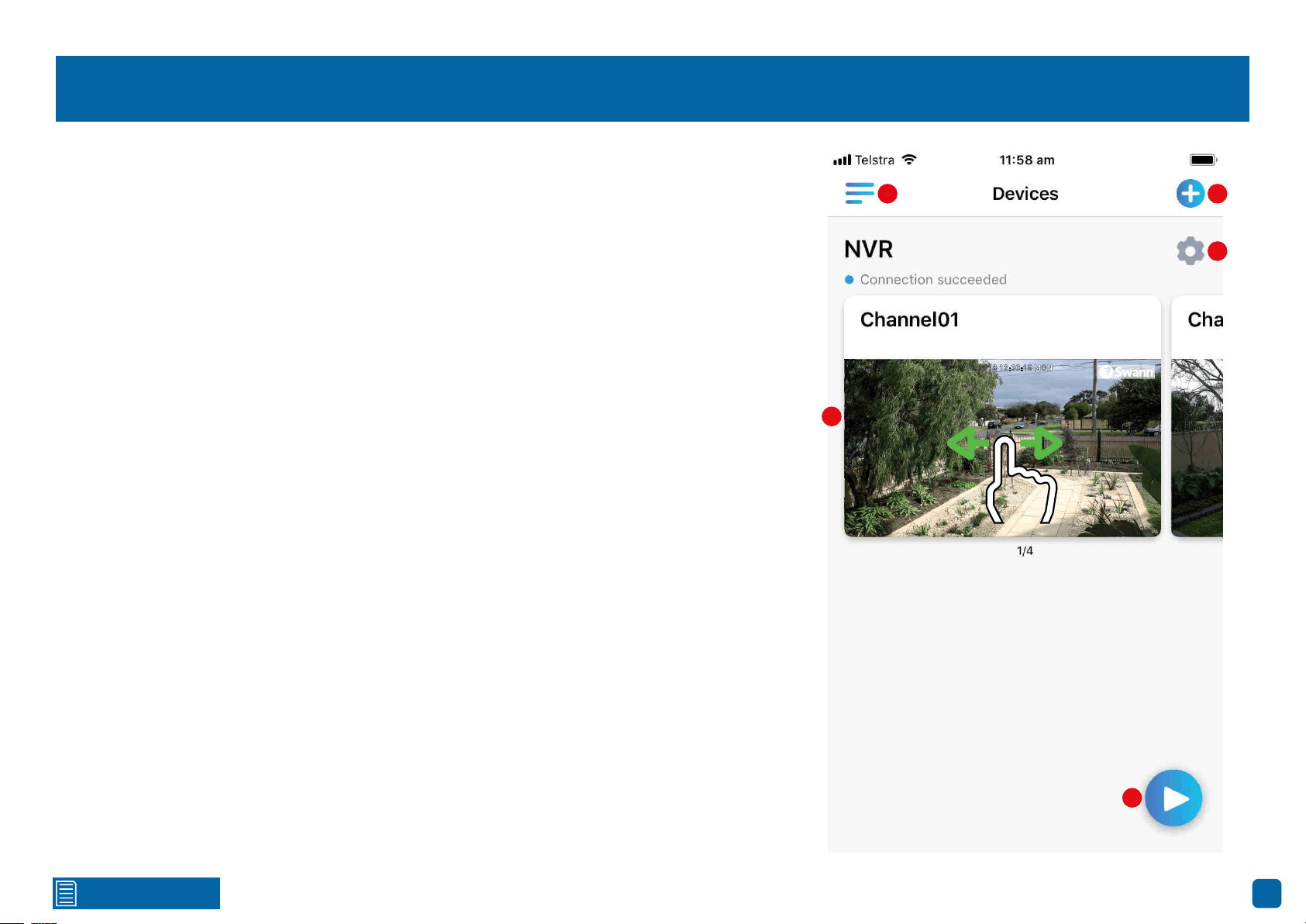
Devices
1. Tap to configure app startup settings and to view general information about the app.
2. Tap to add a device by scanning it’s QR code. You can also add a device by manually entering it’s
UID or IP address.
3. Tap to access Device Settings. From here you can access camera settings, device settings,
changing the recording schedule and much more.
4. The camera preview window. Swipe left or right to select a different camera. Double tap a cam-
era to view it live.
5. Tap this to view the last viewed camera.
22/10/2018 12:30:15 MON
Front door
22/10/2018 12:30:15 MON
Front door
1 2
3
4
5
1 2
3
4
5

Click for contents
48
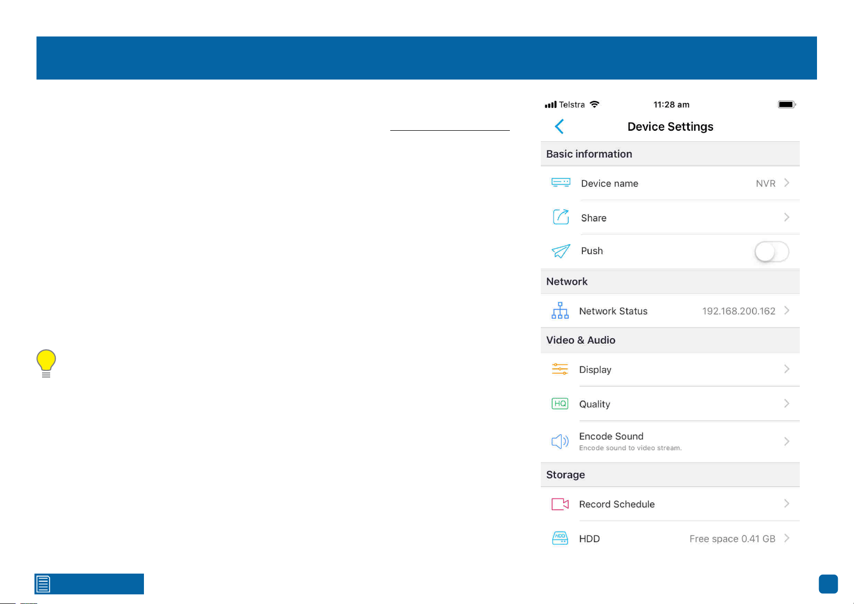
Device Settings: Basic Information/Network
Basic Information
Device Name:
Tap to edit the name of your device. When finished, tap the disk icon to save.
Share: Tap to display a QR code that can be scanned with other mobile devices to share access to
your device. Once scanned, enter the device’s password to login.
Push: Tap the switch to receive notifications when your NVR detects motion from each camera.
Network
Network Status:
Tap to view details about your NVR’s network connection.
Click for contents
49
Device Settings: Video & Audio
Video & Audio
Display:
Tap to customise the camera’s display settings (see page 50 - Device Settings: Display).
Quality: Tap to change settings for the Clear (Mainstream) and Fluent (Substream) video streams:
Resolution: For Clear, the default resolution is 1080P. A lower resolution is available allowing you
to stream at a higher frame rate (up to 25fps). For Fluent, the default resolution be changed.
Frame Rate(fps): The number of frames per second (fps) that your NVR will stream. The higher
the frame rate, the smoother the movement of people and objects will be. If the image appears
delayed or the audio is out of sync when talking to the camera, change the frame rate to lower the
amount of bandwidth required.
Max Bitrate(kbps): Select the maximum bitrate that can be utilized by your NVR to stream video.
The higher the bitrate, the better (finer detail and sharper) the quality of the streaming video will
be, but a fast internet connection with adequate bandwidth is required.
Encode Sound: If audio isn’t required in the video stream, tap the switch to disable.
Please note: In most circumstances, the default settings will be suitable for your NVR to
stream video over a fast internet connection. If the video loads slowly or frequently stops, try
adjusting the settings above to improve performance.
Click for contents
50
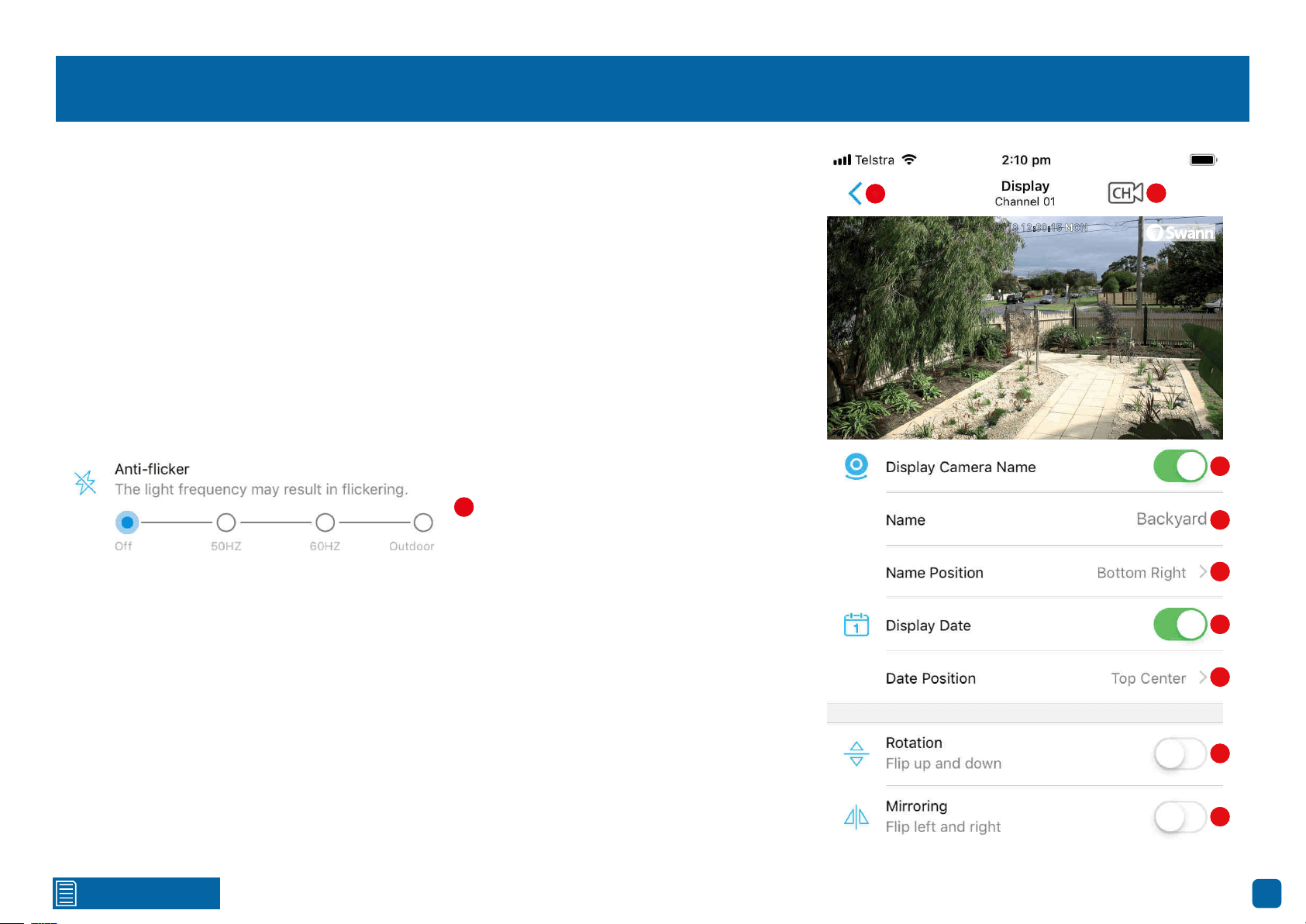
Device Settings: Display
1. Tap to go back to the previous menu.
2. Tap to select a different camera to edit.
3. Tap the switch if you would like to hide the camera’s name.
4. Tap to change the camera’s name.
5. Tap to change the position of the camera’s name.
6. Tap the switch if you would like to hide the date displayed.
7. Tap to change the position of the date displayed.
8. Depending on how your camera has been mounted, tap the switch to flip the image upside down.
9. Depending on how your camera has been mounted, tap the switch to reverse the image.
22/10/2018 12:30:15 MON
Front door
1
2
3
4
5
6
7
8
10
9
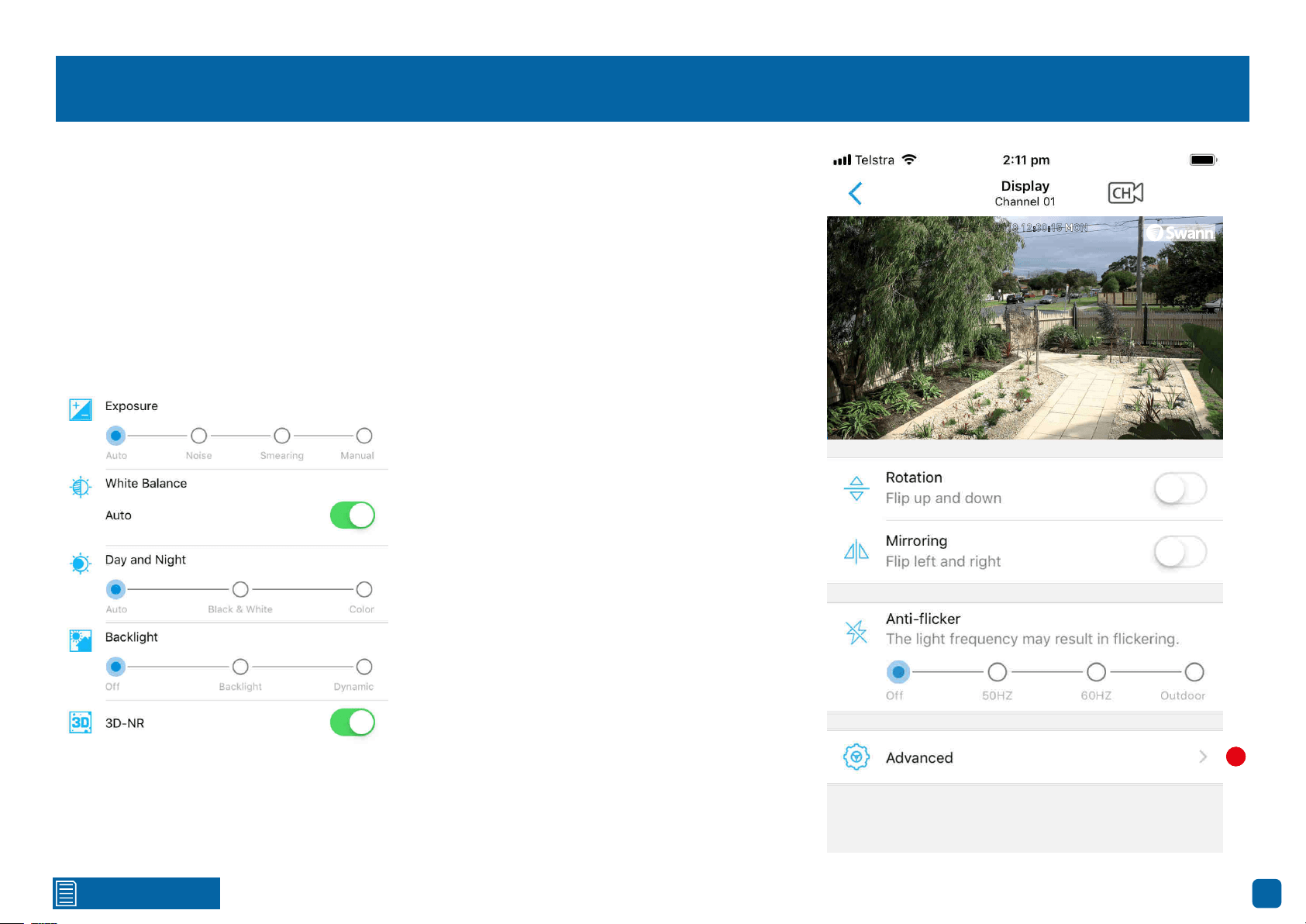
10. This function is used if your cameras are mounted in a location that uses fluorescent light-
ing. As fluorescent lighting operates at the same frequency as your mains power, this will cause
luminance flicker when viewed with the camera. Enabling the anti-flicker function can reduce or
eliminate the flicker that is visible. 50Hz is the mains frequency used in the UK, Australia and most
European countries. 60Hz is the mains frequency used in the United States, Canada and some
Latin American countries. If you don’t see any flicker visible, leave the function disabled.
(continued on next page)
1
2
3
4
5
6
7
8
9
10
Click for contents
51
Device Settings: Display
11. Tap to see the following options:
Exposure: This function controls how the light hits your camera’s image sensor. If the image ap-
pears normal, leave the default setting.
Noise: If people and objects are hard to see in low light conditions, tap this then increase the gain
so they can be seen more clearly. Increasing the gain too much will increase the video noise visible.
Smearing: If fast moving objects are causing a smear effect, tap this and adjust the shutter range.
The higher the number, the slower the shutter speed (a fast shutter speed is recommended).
Manual: This function allows you to control both the gain (Noise) and shutter range (Smearing).
22/10/2018 12:30:15 MON
Front door
11
White Balance: This adjusts for lighting in order to
make white objects appear white in the image. One
of the indicators for an improper white balance are
dark colours which appear faded or a different col-
our altogether. If this is happening, tap the switch
and adjust the red and blue gain levels.
Day and Night: This instructs the camera to switch
automatically from daytime to night-time and vice
versa. It’s recommended to leave the default setting.
Backlight: This improves exposure of an object that
is in front of a light source. This may happen if an
object is in front of a window. Enable this if the cam-
era is mounted in a location where this is required.
Dynamic: This will balance out images that have a
large dynamic range. An example of this would be if
a camera is pointing towards a window. The image
during the day would be extremely washed out due
to the high brightness of the incoming light.
3D-NR: This function will reduce the overall
noise content for recordings done at night or
in lower light conditions. It’s recommended
to leave the default setting.
11
Click for contents
52
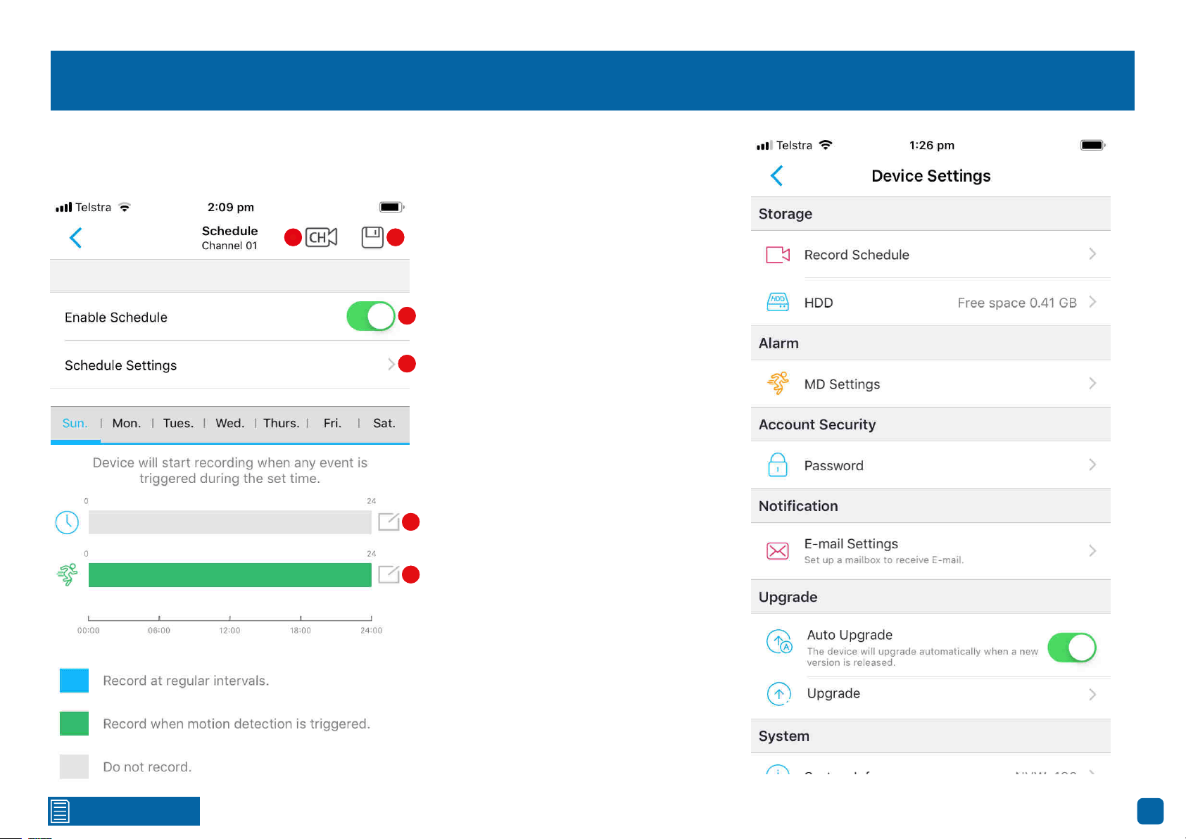
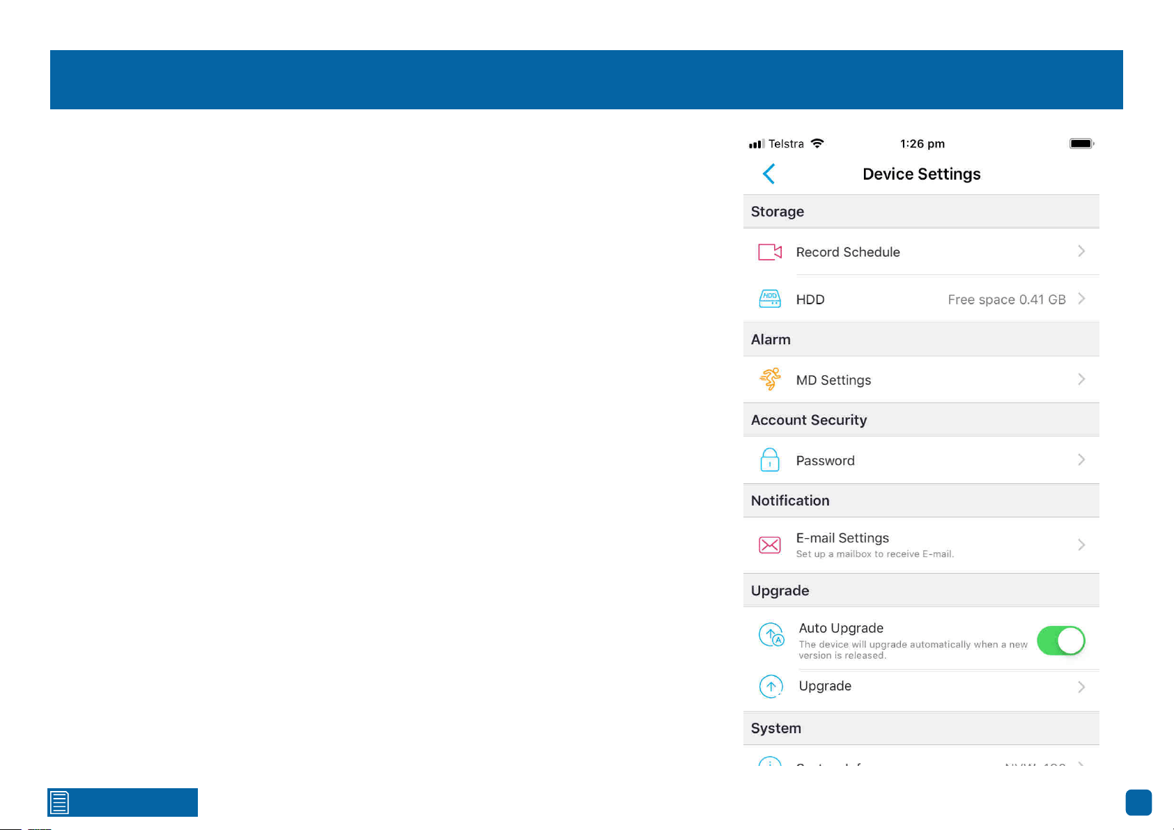
Device Settings: Storage - Record Schedule
Storage
Record Schedule:
Tap to access the recording schedule.
1. Tap to select a different camera to edit.
2. Tap to save changes made.
3. Tap to disable the schedule if needed.
4. Tap to change the schedule.
By default, a motion detection recording
schedule has been enabled for each cam-
era connected.
1 2
4
3
Swipe left or right to select a different day.
The selected day will be highlighted in blue.
5. Known as Normal on your NVR, will con-
stantly record for a set period of time. Tap
here to select required times or tap ‘All” for
24 hours. When finished tap “Done”.
6. Known as Motion on your NVR, will only
record when motion has been detected. Tap
here to select required times or tap ‘All” for
24 hours. When finished tap “Done”.
Tap “Copy To” to copy the schedule to each
day, Monday to Friday, weekend or selected
days.
When finished, go back to the previous
menu then tap the disk icon to save.
5
6
1 2
3
4
5
6
Click for contents
53
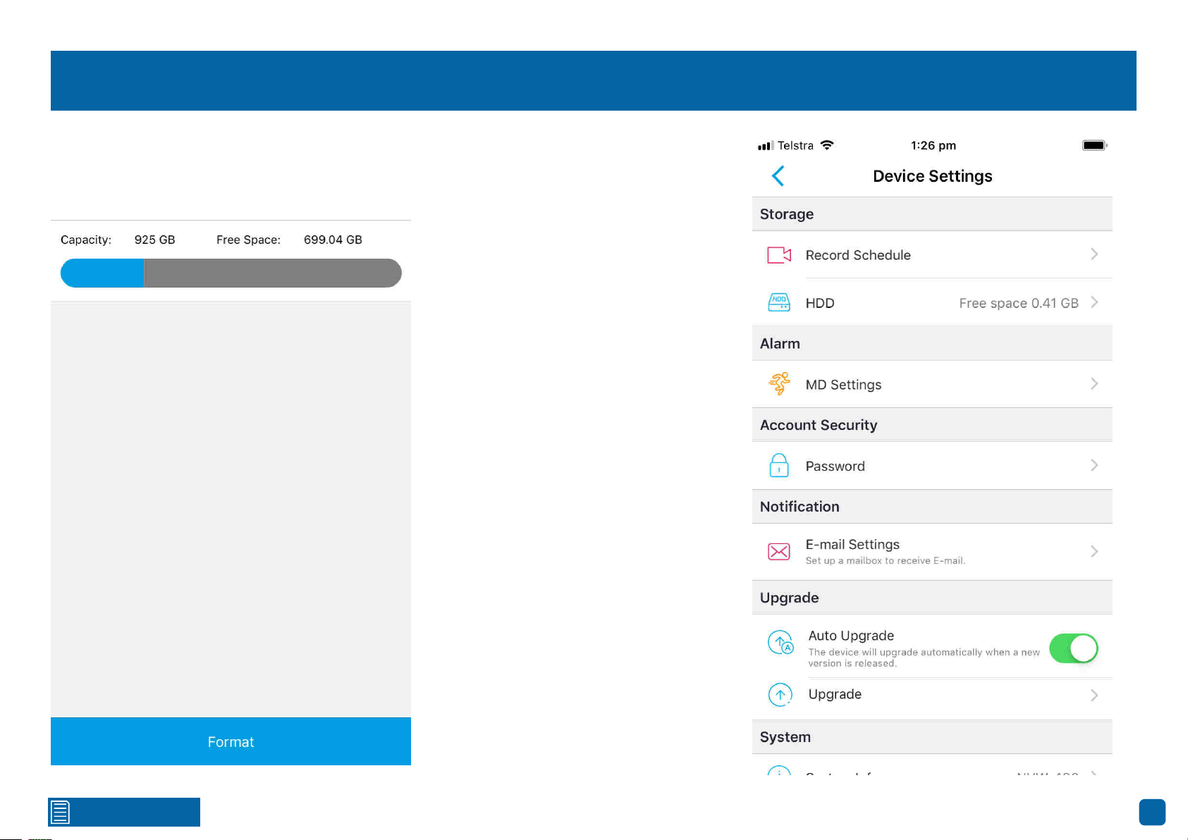
Device Settings: Storage - HDD
Storage
HDD:
Tap to format your NVR’s storage device (internal hard drive, USB hard drive or MicroSD
card). If a new storage device has been connected and installed, it must be formatted before use.
Format: Tap this to commence. A message
will appear stating that all your recordings
will be deleted (If you have any recordings
that are required, back them up to a USB
flash drive). Tap “OK” to continue. The stor-
age device will now format which will only
take a few short moments.
Click for contents
54
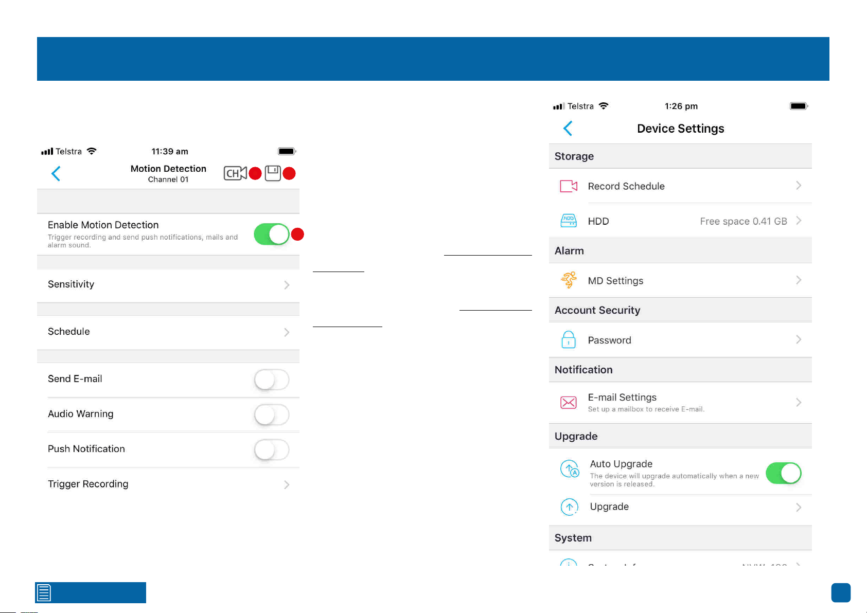
Device Settings: Alarm - MD Settings
Alarm
MD Settings:
Tap to change settings for motion detection.
1. Tap to select a different camera to edit.
2. Tap to save changes made.
3. Tap to disable motion detection if need-
ed.
Sensitivity: Tap to adjust motion detection
sensitivity (see page 55 - Motion Detection
Sensitivity).
Schedule: Tap to change the motion detec-
tion schedule (see page 56 - Motion Detec-
tion Schedule).
Send E-mail: Tap the switch to receive
email notifications when motion has been
detected.
Audio Warning: Tap the switch to enable
the NVR’s buzzer to alert you when motion
has been detected.
Push Notification: Tap the switch to receive
notifications when motion has been detect-
ed.
Trigger Recording: Tap to instruct your
NVR to trigger additional cameras to start
recording when motion has been detected.
1 2
3
1 2
3
Click for contents
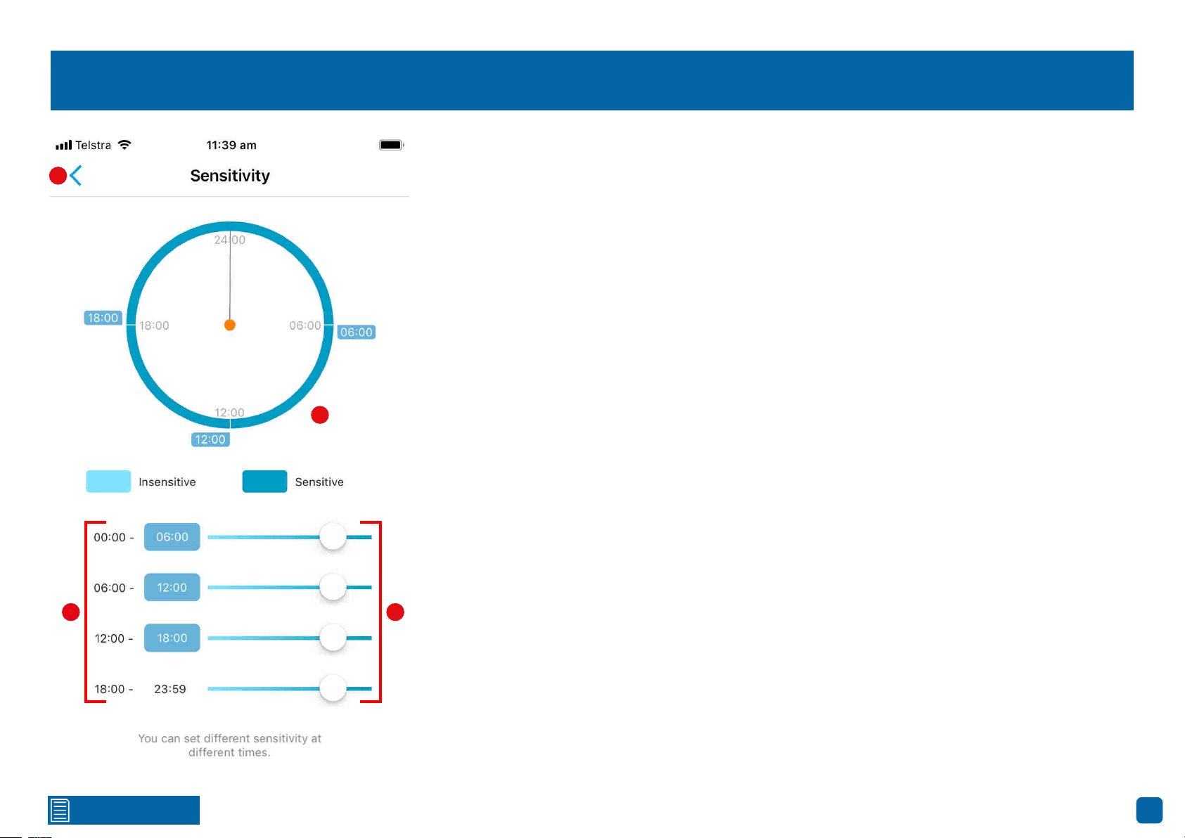
55
Motion Detection Sensitivity
1 2
3
1. Tap the highlighted end time of the first, second or third time period to define the periods in the
day (24-hour format). The start time of the next period will be updated automatically.
2. You can adjust the motion sensitivity of each time period by dragging the slider left or right. As
every home environment is unique, we recommend experimenting with the motion sensitivity to
find what works best for you.
3. The 24-hour graphical display shows you the schedule of the camera’s motion detection sensi-
tivity over the four defined time periods.
4. Once you’ve customised the motion detection sensitivity settings according to your require-
ments, tap this to exit.
Tap the disk icon to save changes made.
4
3
4
1 2
Click for contents
56
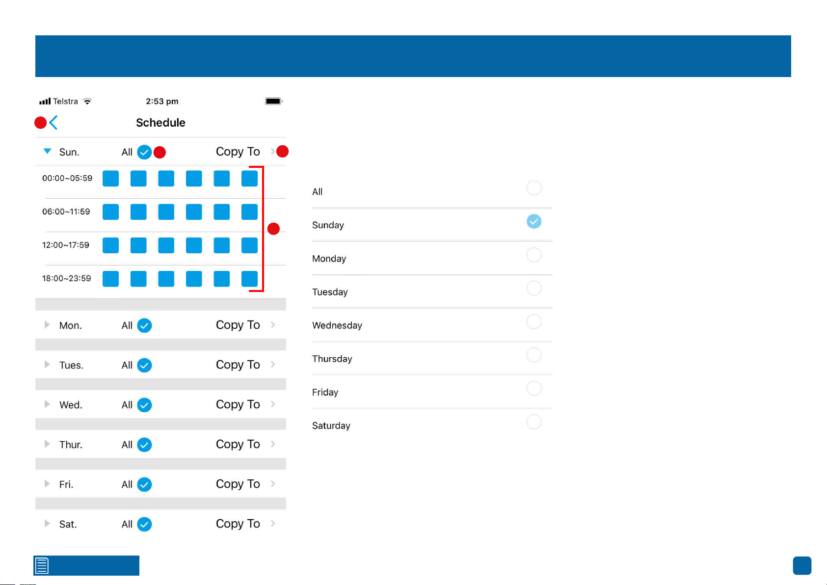
Motion Detection Schedule
1. To remove the current motion detection schedule, tap “All” (the schedule will turn grey).
2. Tap a square to enable (it will turn blue) for each time period. Each square represents 60 min-
utes (24-hour format).
3. Tap to copy this schedule (if needed) to other days of the week (see below).
1
2
3
4
4. Once you’ve customised the motion detection schedule according to your requirements, tap this
to exit.
Tap the disk icon to save changes made.
1
2
3
4
Click for contents
57
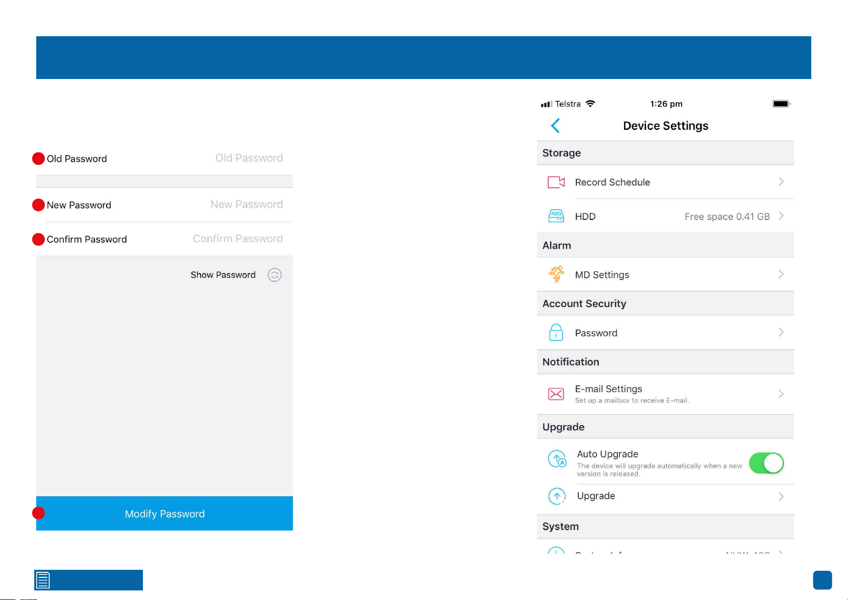
Device Settings: Account Security
Account Security
Password:
Tap to change the login password.
1. Tap to input your current password. Tap
“Show Password” to display your password.
2. Tap to enter a new password. The pass-
word has to be a minimum of six characters
and can contain a mixture of numbers and
letters.
3. Tap to confirm your new password.
4. Tap to save your new password.
1
2
3
4
1
2
3
4
Click for contents
58
Device Settings: Notification
Notification
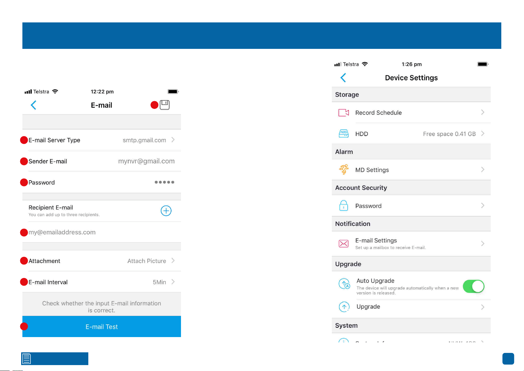
E-mail Settings:
Tap to change the current email settings.
1. Tap this then tap “Gmail” or “Outlook”.
Tap “Other” if you would like to use your
own email server.
2. Tap to input the email address for the ac-
count you created.
3. Tap to input the email password for the
account you created.
4. Tap to input an email address that you
want to send email alerts to. Tap the “+”
button if you would like to send email alerts
to multiple addresses.
5. Tap to select the attachment type (pic-
ture or video) that you want to receive with
your email alerts. Tap “No Attachment” if
attachments are not required.
6. This is the length of time that must elapse
after your NVR sends an email alert before
it will send another. Adjust accordingly.
7. Tap to verify the information you entered
is correct. A “E-mail test succeeded” mes-
sage will appear if successful.
8. Tap to save changes made.
1
2
3
4
5
6
7
8
1
2
3
4
5
6
7
8
Click for contents
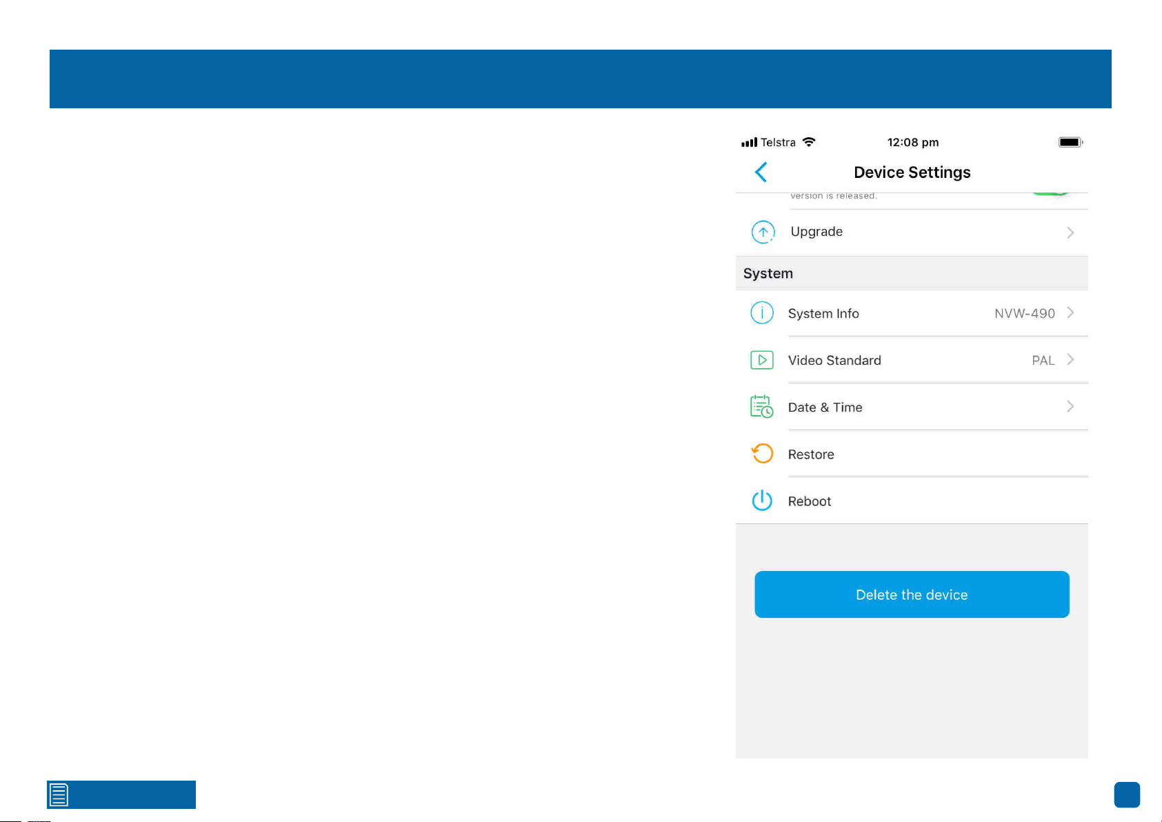
60
Device Settings: System
System Info: Tap to display technical information about your NVR. If you call our helpdesk for as-
sistance, our staff may ask you to access this tab to assist them in solving any technical issues that
you may be having.
Video Standard: Tap to select the correct video standard for your country. USA and Canada are
NTSC. UK, Australia and New Zealand are PAL.
Date & Time: Tap to change the date format, time format, to enable Daylight Saving and to syn-
chronize your NVR’s time with your phone time. Tap the disk icon to save changes made.
Restore: Tap to restore your NVR’s default settings. The Startup Wizard will appear on-screen af-
ter reboot. You will need to re-enter your NVR’s password in AlwaysSafe to access it.
Reboot: Tap to reboot your NVR.
Delete the device: Tap to delete your NVR from the app.
Click for contents
61
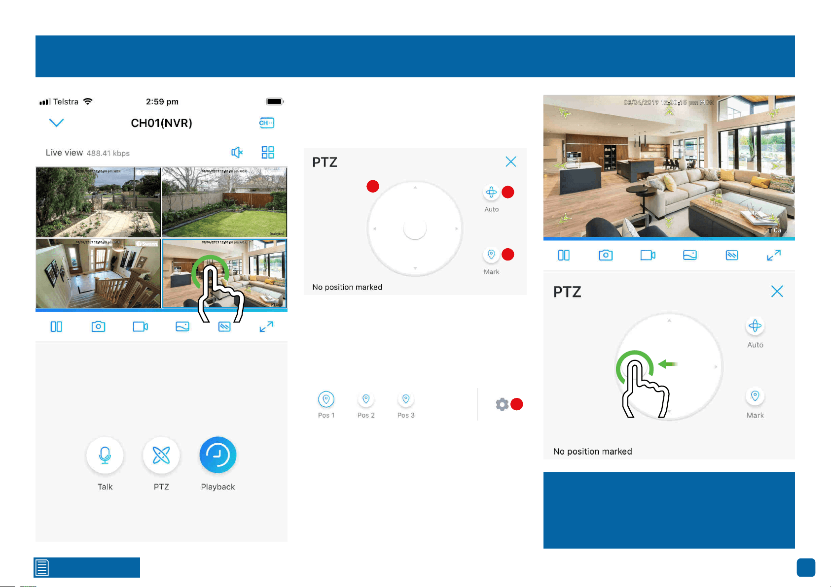
Controlling your Swann PT Cam
08/04/2019 12:30:15 pm MON
Front door
08/04/2019 12:30:15 pm MON
Backyard
08/04/2019 12:30:15 pm MON
Staircase
08/04/2019 12:30:15 pm MON
PT Cam
To control your Swann PT Cam, in Live View
mode tap the channel the camera is config-
ured to then tap the “PTZ” button.
1
2
3
1. Tap and hold the middle button then push in
the direction you want to move the camera to.
2. Tap to pan the camera for 60 seconds.
3. Tap to create a preset position (see below).
To create a preset, move the camera to the de-
sired focal position then tap “Mark”. Give the
preset a name than tap “OK”. Repeat these
steps to create multiple presets. In the exam-
ple above, three preset positions have been
created. Tap a preset to move the camera.
4. Tap to delete one or more preset positions.
4
08/04/2019 12:30:15 pm MON
PT Cam
Tap and hold the middle button then push in the
direction you want to move the camera to. The
green arrows illustrated indicate the directions
available. Tap the “X” button to close.
1
2
3
4
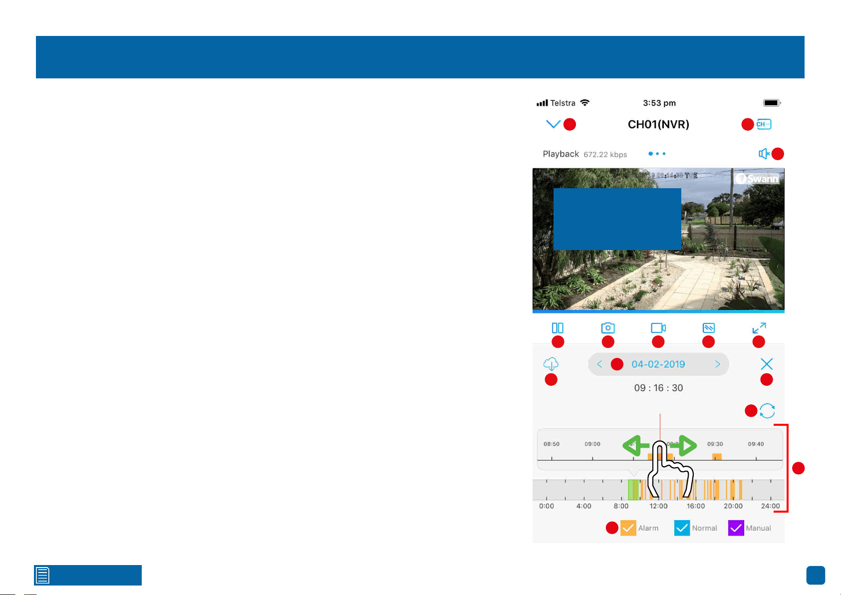
Click for contents
62
Playback
1. Tap to return to the “Devices” screen.
2. Tap this then tap the cameras to enable for playback. When finished tap “Done” to return.
3. Tap to hear or mute the audio.
4. Tap to pause or resume playback.
5. Tap to capture a snapshot. Snapshots are saved to the internal memory of your mobile device
(look for the AlwaysSafe folder).
6. Tap to record a video. Videos are saved to the internal memory of your mobile device (look for the
AlwaysSafe folder).
7. Tap to change the video stream quality between “Fluent” (smoother movement) or “Clear”
(higher quality).
8. Tap for a landscape (full-screen) display of the playback window. Turning your mobile device
horizontally will also do the same thing.
9. Tap to select and download a 30-second (or less) video from a specified time period. Swipe left
or right to select the time period. Tap and hold the mark in and mark out points (green colored) to
edit the video to a specific section required. Tap “Download This Video File” to save.
10. Tap to open the calendar and select a specific date to search for recorded motion events.
11. Tap to return to Live View.
12. Tap to refresh the timeline.
13. Swipe the bottom timeline left or right to narrow down to a specific time period of the day.
The orange highlighted sections represent recorded motion events. The red vertical line in the top
timeline indicates the time when the video will start playing. To zoom in and out on the top timeline,
place two fingers on the timeline and spread them apart to zoom in and pinch to zoom out. Swipe
the top timeline left or right to rewind or fast forward playback.
14. Indicates the video type on the timeline.
04/02/2019 09:16:30 TUE
Front door
1
2
3
4 5
6
7 8
9
10
11
12
13
14
Swipe the screen left
or right to select a dif-
ferent camera.
1
2
3
4
5
6
7
8
9
10
11
12
13
14
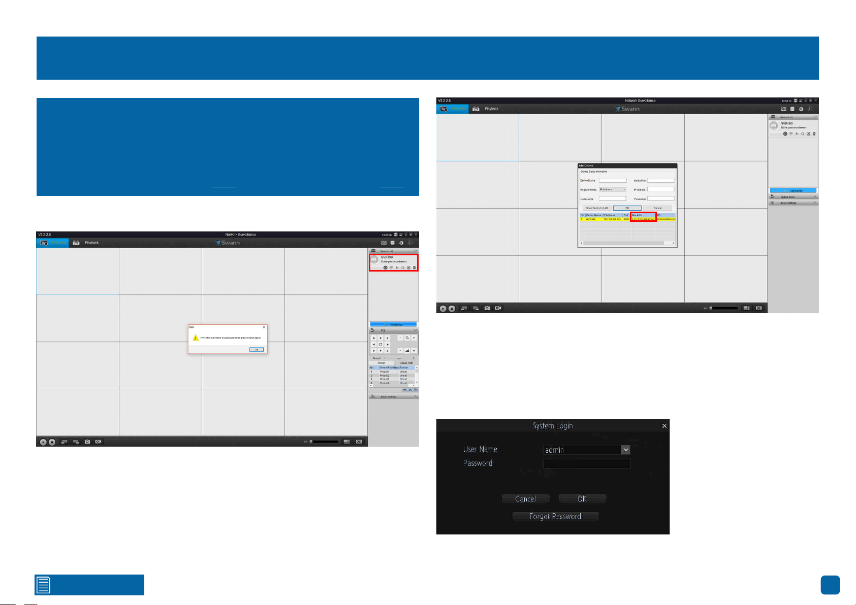
Click for contents
63
Resetting your Password using SwannView Link
2. Your NVR will automatically be detected (top right corner as shown above)
and an error message will appear on-screen. Don’t worry this is normal.
Click “OK” to continue (if your NVR does not appear, check that your device is
connected to your router using the supplied Ethernet cable).
3. To retrieve your recovery code, click “Add Device” (blue button). You will see
the following screen:
4. Your NVR’s MAC Address will be displayed. This is your recovery code that
is used to reset the password. Write this down including the colons (:).
5. Now it’s time to enter the recovery code on your NVR. Right-click the mouse
on the Live View screen to display the Menu Bar then click “Menu”. The login
prompt will appear on-screen:
(continued on next page)
I haven’t created an email for my NVR, what can I do? Don’t worry, you
can use SwannView Link to retrieve your recovery code. You can use this
to reset your NVR’s password. Download the relevant version for your
computer and follow the on-screen instructions to complete installation.
SwannView Link Windows click here. SwannView Link Mac click here.
1. When you first run SwannView Link, you will see the following screen:
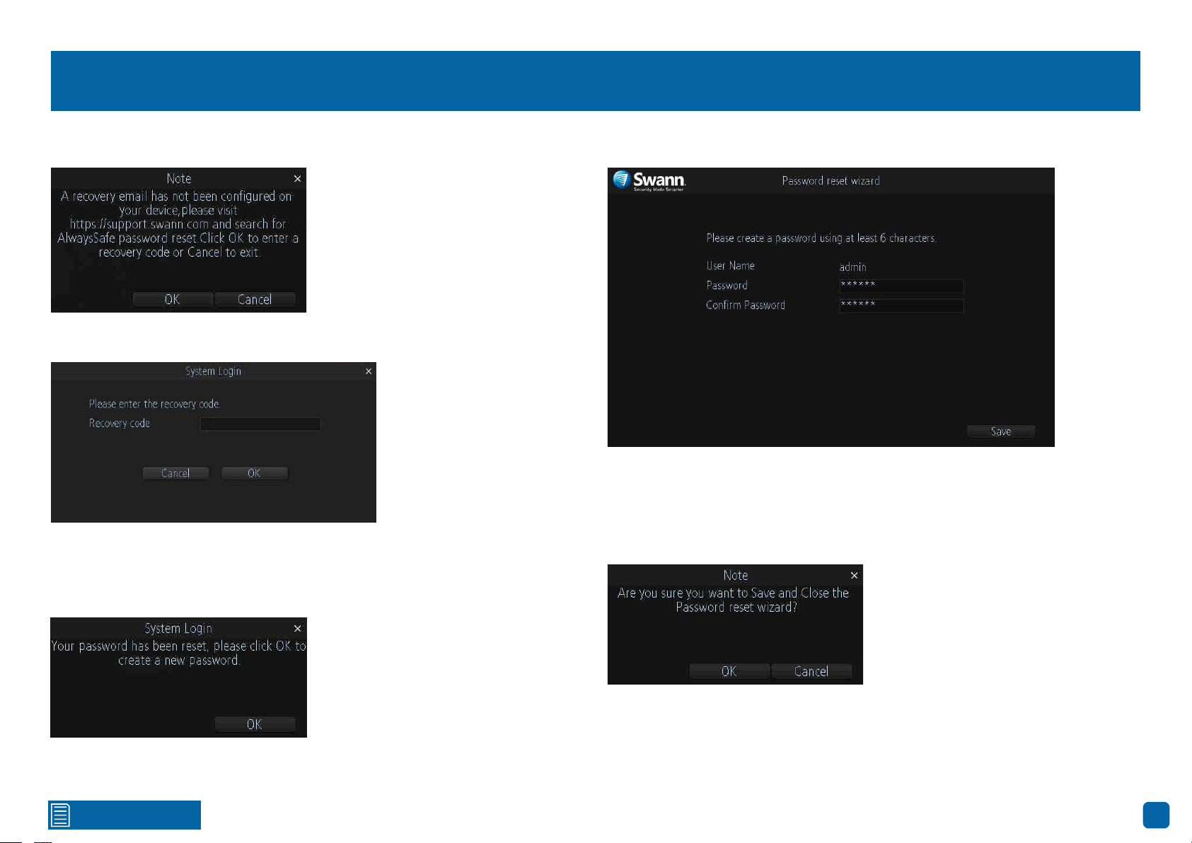
Click for contents
64
Resetting your Password using SwannView Link
6. Click “Forgot Password”. A message will appear on-screen:
Click “OK” to continue. The recovery code prompt will appear on-screen:
Click the dialogue box then enter the recovery code (MAC Address), for
example EC:71:DB:8D:3C:AB then click “Enter”. Click “OK” to confirm. A
message will appear on-screen stating that the password has been reset.
7. You will now be prompted to enter a password:
The password has to be a minimum of six characters and can contain a
mixture of numbers and letters. Use a password that you are familiar with,
but is not easily known to others. Write down your password for safe keeping.
When finished click “Save”. You will now see the following screen:
Click “OK” to finish.
Don’t forget to write down your password: __________________________
Click “OK” to continue.

Click for contents
65
Frequently Asked Questions
Can I play video(s) on my NVR that I have copied to a USB flash drive?
No, your NVR doesn’t have the option to play video(s) from a USB flash drive.
You will have to play them on your computer or mobile device.
What is the largest hard drive that I can install inside my NVR?
The largest hard drive you can install is 4TB (terabyte). We recommend that
you purchase a drive that is surveillance rated such as the Western Digital
Purple™ and Seagate Skyhawk™ range of drives.
Can I connect and record to a portable USB hard drive?
If your NVR doesn’t have a hard drive installed (internally), you can connect
and record to a portable USB hard drive. Both 2.5” and 3.5” USB hard drives
are compatible with a maximum supported capacity of 4TB (terabyte).
Can I connect and copy videos to a portable USB hard drive or MicroSD
card?
No, you can only copy videos to a USB flash drive.
How do I save video recordings that are on my NVR?
To copy video recordings to a USB flash drive, use the Search: Backup func-
tion (see page 32).
What is the largest MicroSD card that I can use?
The largest MicroSD that can be used is 128GB.
Can I use my own email address and server instead of creating a new one?
You can providing you have the settings required for the SMTP port and serv-
er. If you don’t have this, you will have to contact your internet service provid-
er to get this information.
Can I select which storage device that my NVR can record to?
No, your NVR has been configured to record to one storage device at a time.
If a hard drive has been installed internally, it will not detect a MicroSD card
inserted or a USB hard drive connected.
My NVR is recording to a USB hard drive, how can I copy videos to a USB
flash drive?
As your NVR has two USB ports, you need to connect a USB hub to extend
the number of ports available. Connect the mouse and USB flash drive to the
USB hub then connect this to your NVR. You can then copy videos to the USB
flash drive. If you don’t have a USB hub, they can be purchased from most
computer retailers or electronic stores.
What is the wireless range of the cameras, how far can I install them?
There are many factors that can affect wireless range such as the size and
structure of your home, other wireless products within your vicinity and pos-
sible interference from appliances. When your NVR is running in AP mode
the wireless range can be up to 100ft/30m, depending on conditions, with the
typical range being 50ft/15m. In Station mode, as the cameras communicate
with your Wi-Fi access point, you have more flexibility on camera placement
but the same wireless range applies.
My cameras are intermittently disconnecting and reconnecting.
Try placing the cameras closer to your NVR if running in AP mode, or closer
to your Wi-Fi access point if running in Station mode. You can also change the
channel that your NVR and or Wi-Fi access point operates on. All Wi-Fi devic-
es communicate over specific wireless channels. Neighbouring Wi-Fi home
networks that run over the same channel will generate radio interference
that will cause network performance slowdowns (see page 41). Consult the
instruction manual for your Wi-Fi access point on how to change the channel
for that device.

Click for contents
66
Frequently Asked Questions
When scanning the QR code in the Wi-Fi network tab to add my NVR to the
AlwaysSafe app, I get a “UID is invalid” error, what am I doing wrong?
This QR code is for adding cameras to your NVR only. To add your NVR to the
AlwaysSafe app, enter the Wizard from the Menu and scan the QR code there.
I can’t find a way to change the date format, where do I find this?
The ability to change the date format is only available in the AlwaysSafe app
(see page 60).
Can I change display settings such as exposure and white balance for my
cameras?
The ability to change camera display settings are only available in the Al-
waysSafe app (see page 50). You cannot change camera display settings on
your NVR directly.
Is trigger recording supported as I cannot see this function on my NVR?
Yes, you can enable this function in the AlwaysSafe app (see page 54).

Click for contents
67
Glossary
3D-Noise Filter: Is an enhanced form of digital noise reduction. The ad-
vancement in technology enables noise to be filtered even more effectively
from the image, even in low light conditions.
50Hz: Is the mains frequency used in the UK, Australia and most European
countries.
60Hz: Is the mains frequency used in the United States, Canada and some
Latin American countries.
AGC (Automatic Gain Control): In low light conditions, the camera will auto-
matically boost the gain control so that people and objects can be seen more
clearly. The advantage of this technique is that your camera will produce im-
ages in much lower light conditions. The downside is that the amplification
will increase the video noise visible.
AHD: Is an analogue high definition closed-circuit television video surveil-
lance standard that uses coax cable to transmit HD video from security cam-
eras to DVRs. AHD supports 720p and 1080p HD video resolutions.
Anti-flicker: As fluorescent lighting operates at the same frequency as your
mains power, this will cause luminance flicker when viewed through the
camera. Enabling the anti-flicker options available can reduce or eliminate
the flicker that is visible.
Anti-smearing: A smear effect means that a bright vertical line originating
from a bright light source appears in the image. This happens especially with
back lighting. Enabling this allows people and objects to be seen correctly
against a very bright background.
Auto DNS (Domain Name System): A service that stores domain names and
translates them into internet protocol addresses. For example, www.google.
com will have a DNS server address that is equivalent to 74.125.224.72. The
DNS server is automatically provided by your internet service provider.
Auto-focus: Will adjust the lens of your camera to focus on an object being
viewed.
Bandwidth: In computer networks, bandwidth is used as a synonym for data
transfer rate, the amount of data that can be carried from one point to an-
other in a given time period (usually a second). Network bandwidth is usually
expressed in bits per second (bps).
Bitrate: The amount of data that your DVR or NVR will use to record video.
The higher the bitrate, the more space each recording will consume on the
hard drive. Increasing this will also consume more bandwidth when stream-
ing. Unit of measurement is either Mbps (megabits per second) or kbps (kilo-
bits per second).
BLC (Back Light Compensation): Improves exposure of an object that is in
front of a light source. It does this by splitting the whole image into different
regions, and then applying separate exposure levels to those regions.
Brightness: This changes how light the image appears to be. Its value is dif-
ferent in darkness to that in daylight. For example, the lights from car head-
lights appears to be brighter at night.
CDS: This allows the image to be set by the camera’s light sensor. A CDS sen-
sor is basically a resistor that changes its resistive value (in ohms) depending
on how much light is shining onto the sensor.
Cloud: Cloud computing is a model for delivering information technology ser-
vices in which resources are retrieved from the internet through web-based
tools and applications rather than a direct connection to a server. Services
such as Dropbox, Google Drive and Microsoft OneDrive are just some of the
examples of cloud computing.

Click for contents
68
Glossary
Compound Stream: Indicates that your DVR or NVR is recording video and
audio at the same time.
Contrast: This increases the difference between the blackest black and the
whitest white in the image. Without contrast you wouldn’t have an image be-
cause there wouldn’t be any differentiation between light and dark.
Covert: The camera will detect motion and trigger your DVR or NVR to re-
cord, but you will not see an image of the camera in Live View mode.
DDNS (Dynamic DNS): Is a service that converts IP addresses into host names
(a host name is a lot easier than trying to remember an IP address). It also
supports dynamic IP addresses, such as those assigned by a DHCP server.
This makes DDNS a good fit for home networks, which normally receives an
IP address from the ISP that will change occasionally.
DHCP (Dynamic Host Configuration Protocol): Uses an appropriate server
or router to enable dynamic assignment of an IP address to a device connect-
ed to the network.
Display Resolution: Is the number of pixels supported by your TV or VGA
monitor or the output signal of a viewing device, e.g. your DVR or NVR.
DNS Server: Is a standard technology for managing public names of web
sites and other internet domains. DNS technology allows you to type names
into your web browser which your computer will automatically find the ad-
dress on the internet.
DST (Daylight Saving Time): Is the period of the year when clocks are moved
one hour ahead.
DualStream: A process where your DVR or NVR will record both Mainstream
and Substream video at the same time.
Format: Is a command that prepares a storage device such as a USB flash
drive or hard drive to hold data.
Firmware: The software that operates a discrete device (e.g. your smart-
phone). It is referred to in this way rather than software as it is integral to the
operation of the device.
Frame Rate: The measurement of the rate that pictures are displayed to cre-
ate a video feed. The unit of measurement is frames per second (fps).
Gateway: Is a node or router that routes traffic from a device on your home
network to the outside network that is providing access to the internet.
H.264+: Mass video data requires increased storage capacity. To resolve this
issue, video compression technologies are used to reduce the data while
maintaining image quality. H.264+ is an innovative encoding technology
aimed at surveillance video.
H.265: Is a video compression standard and one of several potential succes-
sors to the widely used H.264. It offers double the data compression ratio at
the same level of video quality.
Hardware: A physical device such as your DVR or NVR.
HDD (Hard Disk Drive): Is a storage device located inside your DVR or NVR. It
is where all data is kept, saved and stored.
HTTP Port (Hypertext Transfer Protocol): This port is used to log into the
web browser interface of your DVR or NVR (if available) using a web client,
such as Internet Explorer.
Hue: Is somewhat synonymous to what is usually referred to as colors. By
altering the hue, you can change the color mix of the image.
IP Address: The address of a device attached to the network. Each device on
the network must use a unique address.

Click for contents
69
Glossary
Live View: Is the default display mode for your DVR or NVR. Each camera
connected will be displayed on-screen.
MAC Address: Is a unique identifier for network hardware. Can also be used
as a super password if you have forgotten your current password.
Mainstream: Is the video stream that your DVR or NVR will display and re-
cord.
Mask: Is used to obscure part of your image for privacy. It can also be used
to minimise false triggers when your DVR or NVR detects motion. Any area
obscured won’t be shown live or recorded.
Menu: Is where you control the various actions and options that are available
on your DVR or NVR.
Motion Detection: Is the main method used by your DVR or NVR to detect
motion and is an essential part of your security system. It does this by com-
paring one frame of video with the next. A certain amount of difference be-
tween these two frames is interpreted as motion.
NAS (Network Attached Storage): A network device with one or more HDDs
that other network devices can use as if the storage was connected directly.
NIC (Network Interface Controller): The hardware component that allows a
device to connect to a network. Both wired and wireless NICs exist for these
respective purposes.
NTP (Network Time Protocol): Is used to synchronize your DVR or NVR’s
clock automatically with a network time server. Most time servers are on the
internet.
NTSC: Is the video system used in North America, Canada and some Latin
American countries. In NTSC, 30 frames are transmitted each second.
Optical Zoom: Is a true zoom feature. It allows you to zoom in (or out) on an
object to get a closer view by using the camera’s lens.
OSD (On-screen Display): Display information from the camera such as
time, date and camera name on-screen.
Overscan: Is mainly used on older television sets to display the entire view-
able area correctly on-screen. It does this by cutting off the edges of the pic-
ture. This is not required for modern Plasma and LCD TVs as the image is
digitally processed to display the correct aspect ratio.
Pack Duration: Instructs your DVR or NVR to split recordings into discrete
units. Each unit can be a maximum of 60 minutes in length. Your DVR or NVR
will play these as one continual video.
PAL: Is the video system used in the United Kingdom, Australia and most
European countries. In PAL, 25 frames are transmitted each second.
Post-record: Instructs your DVR or NVR to record for a set period of time
after an event has occurred.
PPPoE (Point-to-Point Protocol over Ethernet): Is the most common meth-
od that your router uses to login to your ISP to enable your internet con-
nection. This setting also exists on the DVR or NVR, but is only for advanced
users as the configuration required is difficult to complete and requires a
modem-only device (or a modem/router set to modem-only).
Pre-record: Allows your DVR or NVR to record for a number of seconds be-
fore an event occurs.
Privacy Zone: See Mask for information.
Resolution: The measure of detail that can be seen in an image. The higher
the number, the greater the detail available.

Click for contents
70
Glossary
RTSP (Real Time Streaming Protocol): A network protocol designed to
transmit video and audio information over networks and the internet in real
time.
Saturation: This alters how much color is displayed in the image. The higher
the saturation, the more bright and vivid colors will appear.
Server Port: Is a logical connection place and specifically, using the internet
protocol TCP/IP, the way a client program specifies a particular server pro-
gram on a computer in a network.
SEQ: Puts the DVR or NVR in sequence mode. This will repeatedly cycle
through each video channel for a predetermined time in Live View mode.
S.M.A.R.T. (Self-Monitoring, Analysis & Reporting Technology): This is an
automatic system on modern HDDs and SSDs to detect potential drive errors
before they occur.
SMTP (Simple Mail Transfer Protocol): This is used to send an outbound
email (e.g. from you DVR or NVR to an email address).
SMTP Port: Is the port number used by a SMTP server to listen for email
send requests. This is specified by your email provider.
SMTP Server: This is the address of the server used for SMTP. Usually in the
form of a web address (e.g. smtp.gmail.com).
Software: A set of instructions that runs on a computing device.
SSID: Is the technical term for a wireless network name. When you setup a
wireless network, you give it a name to distinguish it from other networks in
your neighbourhood.
SSL (Secure Socket Layer): A secure method for connecting to servers. In
the context of the DVR or NVR, primarily used for email server connections.
Static: When referring to IP addresses, this is where a device’s IP address
has been manually entered. Sometimes used on older devices without UIDs
to prepare for internet access.
Static DNS: In some circumstances, your internet service provider may re-
quire you to use a static DNS instead of an auto DNS on your router.
Substream: Is the video stream that your DVR or NVR will send to remote
devices via the network or internet. Video quality is reduced to make it easier
to send.
Subnet Mask: Used to define which part of the IP address refers to the net-
work location.
Time Server: Is a server that reads the actual time from a reference clock
and distributes the information to its clients on the network.
Time Zone: Is a region that observes a uniform standard time for legal, com-
mercial, and social purposes. It is convenient for areas in close communica-
tion to keep the same time.
Timestamp: Is a sequence of characters or encoded information identifying
when a certain event occurred, usually giving date and time of day, some-
times accurate to a small fraction of a second.
Trigger Recording: Enables your DVR or NVR to trigger additional cameras
to start recording when motion has been detected.
TVI: Is a digital signal processing and transport technology for video used in
HD security cameras. TVI cameras currently support 1080p video resolution
using the same coaxial cabling techniques used by traditional analogue CCTV
cameras.

Click for contents
71
Glossary
UID (Unique Identifier): Is an alphanumeric string that is associated with a
single entity within a given system. By entering your UID into the mobile app
or computer software, this allows you to communicate with your DVR or NVR
without having to remember IP addresses or port numbers.
UPnP (Universal Plug and Play): A network protocol designed to allow net-
work connected devices to automatically configure the router for the purpos-
es of remote access. Not required to be enabled when using UID.
VCA (Video Content Analysis): Is a new method for triggering recording and
events. This uses the image processing system of the DVR or NVR & camera
to set specific triggers for recording (such as line crossing or intrusion). This
system does use more processing power, therefore it may not be available on
all devices.
Video Loss: Is regarded as a potential alarm event and is considered to occur
any time your DVR or NVR doesn’t receive an active video signal from any one
of its video inputs.
Video Quality Diagnostics: Enables your DVR or NVR to alert you if the cam-
era has a blurred image, abnormal brightness or unwanted tint in the image
due to the lighting and white balance of the camera (known as Color Cast).
Video Stream: Indicates that your DVR or NVR is recording a video stream
only.
WDR (Wide Dynamic Range): Is technology to balance out images that have
a large dynamic range. An example of this situation would be if an indoor
camera were pointing towards a window or building entrance. The image
produced by the camera during the day would be extremely washed out due
to the high brightness of the incoming light.

Click for contents
72
Warranty Information
USA
Swann Communications USA Inc.
12636 Clark Street
Santa Fe Springs CA 90670
USA
Australia
Swann Communications
Suite 5B, 706 Lorimer Street
Port Melbourne Vic 3207
Australia
United Kingdom
Swann Communications LTD.
Stag Gates House 63/64 The Avenue
SO171XS
United Kingdom
Warranty Terms & Conditions
Swann Communications warrants this product against defects in workmanship and material for a period of one (1) year from its original purchase date. You
must present your receipt as proof of date of purchase for warranty validation. Any unit which proves defective during the stated period will be repaired with-
out charge for parts or labour or replaced at the sole discretion of Swann. The end user is responsible for all freight charges incurred to send the product to
Swann’s repair centres. The end user is responsible for all shipping costs incurred when shipping from and to any country other than the country of origin.
The warranty does not cover any incidental, accidental or consequential damages arising from the use of or the inability to use this product. Any costs associ-
ated with the fitting or removal of this product by a tradesman or other person or any other costs associated with its use are the responsibility of the end user.
This warranty applies to the original purchaser of the product only and is not transferable to any third party. Unauthorized end user or third party modifications
to any component or evidence of misuse or abuse of your device will render all warranties void.
By law some countries do not allow limitations on certain exclusions in this warranty. Where applicable by local laws, regulations and legal rights will take
precedence.
For Australia: Our goods come with guarantees which cannot be excluded under Australian Consumer Law. You are entitled to a replacement or refund for
a major failure and for compensation for any other reasonably foreseeable loss or damage. You are also entitled to have the goods repaired or replaced if the
goods fail to be of acceptable quality and the failure does not amount to major failure.

M490_REV2E080419 | © Swann 2019
Security Made Smarter
Firmware Version: Build 1812120 GA 3.1
Help & Resources
Visit Swann Support Center at support.swann.com. You can register your product for dedicated
customer support, download guides, find answers to commonly asked questions, and more.
Tell us what you think!
We are constantly working to improve
the quality of our documentation, and
we would appreciate your feedback.
Click here to complete a short survey.
Product Registration
Product Manuals
Support Community
Customer Support
Frequently Asked Questions
