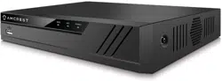
The front panel of the NVR may differ model to model. Below is a representation of the front panel for all applicable NVR devices.
Applicable for the NV2104/NV2104E/NV2108/ NV2116/NV2108E/NV4108E-HS/NV4116E-HS
Icon
Name
Function
NET
Network abnormality indicator light
When a network error occurs or there is no network connection, this light turns red.
PWR
Power indicator
When NVR is on, this light remains on.
HDD
HDD abnormal indicator light
When an HDD error occurs, or the HDD capacity is below the specified threshold value, this light turns red.
Older model NVR systems.
SN
Icon
Name
Function
1
USB port
To connect USB storage device, USB mouse, etc.
2
Alarm
Alarm indicator
When an alarm occurs, the light becomes red.
3
REC
Record indicator
When the NVR is recording, the light turns red.
4
HDD
HDD abnormal
indicator light
HDD error occurs, or HDD capacity is below specified threshold value, the light becomes red to alert you.
5
NET
Network abnormal indicator
Network error occurs or there is no network connection, the light becomes red to alert you.
6
ACT
Remote control
indicator
When the NVR receives a signal from the remote, the light will blink.
7
POWER
Power indicator
When NVR is on, the light is on.
8
ESC
ESC
Go to previous menu or cancel current operation.
When playback, click it to restore real-time monitor mode.
9
FN
Assist
One-window monitor mode click this button to display assistant function: PTZ control and image color.
10
Enter
ENTER
Confirm current operation
Go to default button
Go to menu
11
Power button
Power button press this button for three seconds to boot up or shut down NVR.
12
▲, ▼
Up
Down
Activate current control, modify setup, and then move up and down.
Increase/decrease numeral.
Assistant function such as PTZ menu.
◄, ►
Left
Right
Shift current activated control.
When playback, click these buttons to control playback bar.
Rear Panel
The rear panel of the NVR may differ model to model. Below is a representation of the rear panel of all applicable NVR devices.
NVXXXX-Series is shown below.
Port Name
Connection
Function
USB2.0 port
USB2.0 port. Connect a mouse, USB storage device, USB burner, etc.
Network port
10M/100Mbps self-adaptive Ethernet port. Connects to the network.
HDMI
High
Definition
Media
Interface
High definition audio and video signal output port.
It transmits uncompressed high definition video and multiple channel data to the HDMI port of the display device. HDMI version is 1.4.
VGA
VGA video
output port
VGA video output port. Outputs analog video signal. This connects to the monitor to view analog video.
GND
Ground end
Power input port
Power socket.
For NVXXX series, inputs DC 12V/2A.
For NV4432 series, inputs DC 48V/1.25A.
MIC IN
Audio input
port
Bidirectional talk input port. This is used to receive the analog audio signal from the devices such as a microphone.
MIC OUT
Audio
output port
Audio output port. This is used to output the analog audio signal to devices such as an amplifier.
Bidirectional talk output.
Audio output on 1-window video monitoring.
Audio output on 1-window video playback.
PoE PORT
PoE port
Built-in switch. Supports PoE.
For PoE series products, you can use this port to provide power to the network cameras.
Hardware Setup
Before setting up the NVR, you will need the following items. These items may not be included:
A computer monitor or TV with either an HDMI or VGA input
A power strip with room for 4 large power plugs
A hard drive for storing video recordings.
A USB flash drive formatted to FAT 32 for importing/exporting configure or image files.
It is recommended to connect all components before mounting any of the cameras. This is to ensure all components are working properly before they are physically installed. If any components are not functioning, please contact Amcrest Support:amcrest/contacts
There will be two parts to this section:
A hard drive must be installed to record or save any footage. If no hard drive is installed, you can only view the cameras from the NVR. If a microSD card is installed in the camera you can still view the recordings from the microSD card using the Amcrest View Pro application and accessing the camera directly, however, no recordings will be retained to the NVR if a hard drive is not installed.
Hard drive installation
A hard drive can be installed if you want to record and save data to the NVR. Having a hard drive allows you to configure and use the recording functionality of the NVR to store and view events.
Most NVRs have connections for only one hard drive however some models have the option for multiple hard drives inside the case. A hard drive used in these NVRs must be no larger than 8TB (Terabytes). To install your hard drive, the following is needed:
A medium sized (regular) Phillips-head screwdriver - not included
A hard drive - not included
Four hard drive fastening screws - included
Note: Before installing the hard drive, make sure the NVR is powered off with the power cable disconnected.
1. Loosen the screws on the upper cover and side panel.
2. Attach four screws on the hard drive (HDD). Do not fully tighten, only tighten about 3 times.
3. place the HDD in accordance with the four holes on the bottom of the casing.
4. Turn the NVR upside down and place the screws in firmly.
5. Tighten the HDD screws firmly to the bottom of the NVR.
6. Connect the HDD cable and power cables to the
motherboard.
7. Place the cover back onto the NVR in accordance with the clip and place the upper cover back onto the device.
8. Secure the screws on the rear and side panels.
Setting Up the Cables
The following instructions will show you how to set up the cables for the NVR, cameras (PoE and Wi-Fi), as well as a monitor or TV screen.
To set up the cable connections, there are 5 major steps:
1. Connect a monitor or TV screen to your NVR. The NVR is compatible with any monitor or screen that uses a VGA or HDMI connection. For purposes of this guide, we will use a VGA connection. Take a VGA cable, and connect one end to the VGA port on your monitor/screen and the other end to the VGA port on the back panel of your NVR.
2. Connect an Ethernet cable to your router.
Then, connect the other end of the cable to the Ethernet port on the back of the NVR.
3. Connect the cameras to power.
For PoE NVRs/cameras: connect an Ethernet cable to the Ethernet port attached to the camera.
Then, connect the other end of the Ethernet cable to a PoE port on the NVR.
Note: PoE cameras can either be powered with a PoE connection or with a standard power adapter (sold separately). If the NVR does not have PoE ports, connect the PoE camera to a PoE compatible router or switch that is on the same network as the NVR.
For non-PoE NVRs/cameras: Connect the power adapter to the power port attached to the camera.
Then, plug the adapter into a wall outlet or power strip.
4. Connect the NVR’s power adapter into the power port on the back of the NVR.
Note: If your NVR has a 3-prong power cord, connect the input of the cord into the power input of the NVR.
5. Finally, connect the other end of the power cable into a wall outlet or power strip to turn on the NVR. Some models may feature a power switch on the back which may need to be turned on to power the device.
Alarm Connection
Alarm connections may not be applicable to all model NVRs. This section is only for NVRs with a built-in alarm port connection.
Alarm Port
The alarm port is shown as below. See Figure 2-6. The following figure is based on the 78 series.
Note
Different models support different alarm input ports. Please refer to the specifications sheet for detailed information.
Slight differences may be found on the alarm port layout.
Alarm input port
Connect the positive end (+) of the alarm input device to the alarm input port (ALARM IN 1~2) of the NVR.
Note
When connecting the ground port of the alarm device to the NVR, you can use any of the GND ports ( ).
When there is peripheral power supplying the alarm device, ensure it is grounded on the NVR.
Alarm input and output port
There is peripheral power supplying to the external alarm device.
An overload may result in NVR damage. Please refer to the following relay specifications for detailed information.
Alarm relay specifications
Contact Material
Silver
Rating
(Resistance Load)
Rated switch capacity
30VDC 2A, 125VAC 1A
Maximum switch power
125VA 160W
Maximum switch voltage
250VAC, 220VDC
Maximum switch current
1A
Insulation
Between contacts with same polarity
1000VAC 1minute
Between contacts with different polarity
1000VAC 1minute
Between contacts and winding
1000VAC 1minute
Surge voltage
Between contacts with same polarity
1500V (10×160us)
Length of open time
3ms max
Length of close time
3ms max
Longevity
Mechanical
50×106 MIN (3Hz)
Electrical
200×103 MIN (0.5Hz)
Temperature
-40ºC ~+70ºC
Audio Ports
Device-end to PC-end
Device Connection
Connect an RCA microphone to the “Audio In” port on the back of the device. If using an audio out device, such as an RCA speaker, plug the speaker into the “Audio Out” port on the back of the device.
Most audio codecs will use ACC as a default audio codec. To adjust audio settings, log into your NVR and access the Encode menu for the specific device and click on “More Setting” (Camera > Encode > More Setting). Verify the codec and settings are correct and click Save to save the audio settings.
Mouse Operation
Please refer to the following sheet for mouse operation instructions.
Left mouse
click
When you have selected one menu item, left mouse click to view the menu content.
Modify a checkbox or motion detection status.
Click a combo box to show the dropdown list
In an input box, you can select different input methods. Left click the corresponding button on the panel to input a numeral/English character (small/capitalized). Here ← stands for backspace. _ stands for space. In English input mode: _ stands for inputting a space icon and ← stands for deleting the previous character.
In numeral input mode: _ stands for clear and ← stands for deleting the previous numeral.
Double left
Implement special control operations such as double click one item in the file list to playback the video.
mouse
click
In multiple-window mode, double left click one channel to view in full-screen. Double left click the current video again to go back to previous multiple-window mode.
Right click
mouse
In real-time monitor mode, this pops up a shortcut menu.
Exit the current menu without saving any modifications.
Scroll middle button
In a numeral input box: Increase or decrease the numeral value.
Switch the items in the check box.
Page up or page down
Move mouse
Select current control or move control
Drag mouse
Select the motion detection zone
Select the privacy mask zone
Device Installation
After applying power to the NVR, the system will turn on. Allow the NVR to finish loading. The Device Initialization screen will appear. Select your location, language, and video standard then click Next to continue.
Select your time zone as well as current date and time. Click Next to continue.
Enter Password
Create a new admin password for your NVR. The password for your device should be between 8 and 32 characters. A combination of letters, numbers, and symbols are recommended when setting up your password.
Note: Please do not use special symbols like ‘ ‘ ; : &
Once you have entered a new password for your device, confirm the password in the next field.
Lastly, you will be asked to enter a prompt question for your account. This is useful if you have forgotten your password and would like an easier way of recovering your password. Please use a prompt question that will help you remember the password for your device.
After you have completed this section, click Next to continue.
Unlock Pattern
This is an optional security measure for your device. To set an unlock pattern, use your mouse to draw a design that you will remember. Draw the pattern again to confirm. If you do not want to assign an unlock pattern, you can click ‘Skip’ to skip this process.
If you have assigned an unlock pattern, you will need to draw the pattern again to confirm your assigned unlock pattern.
Password Protection
Additional means of password protection and retrieval can be set up in this menu. If you would like to reset your password using your email, make sure the email address checkbox is enabled and enter a valid email address in the Email Address field. The email address will be retained in the system.
If you do not want to use an email address you can disable the email address option. As a secondary means of recovering your password, you can apply security questions to your NVR. To add a question, select a question from the drop-down menus for Question 1, Question 2, and Question 3 and enter the answers to those questions in the Answer fields.
Once this section is complete, click on the Save button to save your information to the device.
Startup Wizard Walkthrough
The first page of the Startup Wizard will appear which allows you to setup any General, Network, Remote Devices, and Record Control Settings for the NVR.
Before proceeding please note, most Amcrest products are H.265 compatible. H.265 provides a more advanced technology than H.264 and allows the device to reduce file sizes which in turn helps to reduce required bandwidth without sacrificing frames per second (FPS) or resolution. However, for maximum compatibility when accessing your device in a web browser, or other third-party applications, our H.265 compatible products will come factory default to H.264.
For optimal performance, the device's compression can be upgraded to H.265 during the camera registration process.
To begin the startup wizard, click Next.
General
The first screen that appears in the startup wizard is the GENERAL menu. The General menu allows you to edit the name of the NVR, display number of devices, languages, etc.
Once you are satisfied with the settings on this screen click Next to continue.
Date & Time
The Date & Time settings screen is used to set the date and time for your NVR. If you want to utilize daylight savings time, click on the DST enable toggle switch. This should be enabled by default. Click Next to continue.
Note: Make sure to toggle the NTP toggle switch to the off position if you do not want to sync your device to an NTP server.
Holiday
This screen allows the user to set and modify holiday settings which allows the NVR to record or send snapshots based on specific schedules set by the user. Please note, a holiday record / snapshot setup has a higher priority than an ordinary date record/snapshot setup plan. Below is a screenshot of the Holiday settings screen:
To add a holiday schedule to your NVR, click on the Add Holidays button. This will take you to an “Add Holidays” screen. Name the holiday you would like to add and select a mode, range, start time, and end time. If you would like to add more holidays, click on the Add More toggle switch, and repeat the process. Click Add to add the holiday(s). Click Next to continue.
Network
The next screen that appears will be the Network, or TCP/IP screen. Unless you have a specific reason to change these settings, it is best to leave them as they are. Please note, the IP address for the NVR will be the address used to access your NVR’s web user interface on a laptop or PC.
Click the Test to test the overall health and status of your network connection once complete, click the Back button to return to the previous menu.
To continue with the startup wizard, click Next.
P2P
The next screen that appears is the P2P screen. This screen allows you to connect your NVR to your mobile device via the Amcrest View Pro app. The P2P status should read as “Online”. To download the app, use your mobile device’s camera and scan the Cell Phone Client QR code. When using the app, use the SN QR Code for quick access to the serial number for your NVR.
Click the Next to continue.
Camera Registration
The next screen that appears is the Camera Registration screen. This is where you can begin adding cameras to the NVR. If the cameras are not directly connected to the back of the NVR, please make sure they are active and on the same network as the NVR before proceeding.
To begin adding a device, click on Device Search to allow the NVR to scan for connected devices on your network.
A list of applicable connected devices will show on the screen. Select your devices by clicking on the checkbox next to the device and click Add to add the device into the Added Devices menu.
If the status of your camera is red, it indicates the camera is not properly connected to the NVR. This could be because the password for the camera is not entered properly in the system.
To modify the password for your camera, click on the edit icon (pencil) located in the Edit column in the Added Device menu.
Select the Password field and use the onscreen keyboard to enter the password for your camera. Once the password has been entered, click Connect then click Save to continue.
Note: If this is a new device and a password has not been added the password will be admin.
Once the password has been properly set the Status indicator will turn green indicating the camera has been properly added.
As previously stated, our H.265 compatible products will come factory defaulted to H.264 compression, but for increased performance, the camera's settings can be automatically switched to H.265 compression. Switching to H.265 compression reduces bandwidth without sacrificing frames per second or resolution. To activate H.265 compression, click on the H.265 Auto Switch.
For more information on H.265 compression, please visit: amcrest/supportClick on Next to proceed.
Schedule (Rec)
The next screen you will see is the Rec screen which allows you to set recording schedules for regular (24/7 continuous recordings), motion detection, alarm, motion & alarm, and POS recording types. For more information on setting a recording schedule, please see section, “Setting Up Recording Schedules”.
Click Next to continue.
This will take you to the snapshot settings for scheduled recordings. This screen is used similarly to the Rec menu only it pertains only to snapshot events. Once you have scheduled your events, click on the OK button to continue.
Once the setup process is finished you should see a dialog box indicating the startup wizard is finished. Click Save to continue
The next screen you will see will be the video wall screen which will display all connected devices. Right click on the video wall and click on the ‘Main Menu’ from the selections to access the main menu.
Main Menu Overview
The screenshot below is the main menu screen for the Amcrest NVR console interface:
Below are short descriptions for each of the menu items on the main menu:
PLAYBACK: View, search, and play recorded videos.
ALARM: View and search live alarm information. Configure alarm event actions. OPERATION: View system information, system updates. Import/export configuration files, etc. BACKUP: Search and backup files using a USB flash drive.
DISPLAY: Configure resolution and display settings.
AUDIO: Configure audio announcements and import audio files.
Management
CAMERA: Add, search, review or edit settings for each camera, including video settings (e.g. quality, bit rate, color, etc.).
STORAGE: Set motion detection schedules, as well as access the hard drive management interface, FTP, etc.
SYSTEM: Review and edit general system settings such as, video standards, date & time, as well as adjust firewall settings.
ACCOUNT: Add or remove shared user settings, groups, as well as ONVIF users. Reset security questions and update reset password email.
Adjusting Camera Settings for Maximum Resolution, FPS, and Bitrate
Most Amcrest products are H.265 compatible. H.265 provides a more advanced technology than H.264 and allows the camera to reduce file sizes which in turn helps to reduce required bandwidth without sacrificing frames per second (FPS) or resolution. However, for maximum compatibility when accessing your device in a web browser, or other third-party applications, our H.265 compatible products will come factory default to H.264. For optimal performance, the device's settings can be upgraded to H.265 compression if needed.
Please note, for higher performance as well when using H.265 compression it is recommended to adjust bitrate. The bitrate is the number of bits that are processed per unit time by the system and helps the system to create a tradeoff between bandwidth and image quality.
How to Adjust to H.265 Compression
If the auto switch for H.265 compression was not selected in the camera registration process, the setting can be adjusted manually. On the Main Menu, under Management, click on Camera.
In the Camera menu, select Encode and click on the Compression drop down menu and select H.265.
Click Apply to save your settings.
Adjusting Bitrate
Since H.265 compression uses roughly 30% less resources than H.264, the camera will typically come defaulted to a preset bitrate when switching to H.265. For instance, when switching to H.265 on a 4K camera, the bitrate may be defaulted to 8192 Kb/S, however, adjusting the bitrate to a lower value may help to increase the overall efficiency of the camera while viewing playback or watching live view.
To adjust the bitrate, access the Encode menu and click on the Bit Rate (Kb/S) dropdown menu. A list of preset bitrates will be displayed as well as a Customized selection which will allow you to set a customized bitrate if needed.
Please note, when using a 4K camera, it is recommended to keep the bitrate around 1792 Kb/S, however, different values may be applicable depending on your specific network requirements.
Please refer to the table below regarding recommended resolution and bitrates and custom thresholds.
Resolution
Recommended Bitrate
Custom Bitrate Threshold
5MP
1536 Kb/S
1792 Kb/S
8MP (4K)
1792 - 2048 Kb/S
1825 Kb/S
Note: Adjusting the bitrate to anything lower than the recommended bitrates above may result in degradation to recordings or to live view. For best results, if you are adjusting multiple cameras, it is highly recommended to adjust each camera individually. This may be a trial and error process since most network environments are unique and may vary, however, the bitrate should range between 1792-2048 Kb/S if using a 4K camera. An optimal customized bitrate should be around 1825 Kb/S. Click Apply to save the new bitrate settings.
Video Wall
Please note the displayed window amount may vary depending on how many channels your NVR can support. The following figure is for reference only.
Please note, the video wall menu will also provide a separate portion that will display the current bit rate of each channel. The bitrate for each device is measured in Kb/S. For more details on bitrate and its relation to the NVR, please refer to the section
Preview Control Interface
Move the mouse to the top center of the video of the current channel, and the system pops up the preview control interface. If your mouse stays in this area for more than 6 seconds and preforms no operation, the control bar automatically hides.
Instant Playback
Click this button to instantly playback any previous motion detection events that were captured by the camera. Please note, a hard drive must be installed in the device to playback any recorded events or snapshots.
Digital Zoom
This option allows you to digitally zoom in on a specific area on the live view interface. To use digital zoom, click the digital zoom button and click an area on the live view screen. Drag the mouse to select a zone and release. The live view will zoom in on the set area. To exit digital zoom, right click on the live view screen to return to its original view.
Manual Record
This option allows you to manually record video. Please note, the NVR can only record videos of a single channel at a time, if multiple channels are enabled, no footage will be retained. To manually record video, insert a USB flash drive into a USB port on the NVR and click on the manual record button. Click on the manual record button again to stop recording. The recording will be saved to the USB flash drive.
Manual Snapshot
Like the manual record button, this option allows you to manually snapshots. To manually take a snapshot, insert a USB flash drive into a USB port on the NVR and click on the manual snapshot button. The snapshot will be saved to the USB flash drive.
Audio talk
This option allows for bidirectional talk. Please note, an external microphone and speaker will need to be applied to the audio in and audio out ports on the back of the NVR for this to function. To activate, click on the audio talk button and use an external RCA microphone and speaker to talk. To disable this function, click on the audio talk button again.
Switch Stream
This option allows the device to switch between main stream and sub stream feeds. Please note, switching to a sub stream feed will provide less quality than a main stream feed.
Adding Additional Devices
To add multiple devices from the video wall interface. Hover the mouse over the channel you would like to select and click the (+) icon.
This will take you to a camera registration screen. Click on Device Search or Manual Add to begin adding the device. If using Device Search, please make sure the camera is on the same network as the NVR before searching. Once the camera has been detected, click on the device to highlight it, and click Add.
Please note, if the device is not registering to the device, the username or password may need to be updated for the camera. This can be resolved by right clicking on the screen and choosing Camera Registration.
In the registration screen, click on the Edit icon (pencil) and ensure the username and password are correct and click Connect. Once this is verified click Save. The status indicator for the camera should turn green, indicating the camera has been added successfully.
Note: For maximum compatibility when accessing your camera in a web browser or third party applications, our H.265 compatible products will be factory defaulted to H.264 but for increased performance, the camera's settings can be upgraded to H.265 compression. H.265 provides a more advanced technology than H.264 and allows the device to reduce file size which ultimately helps to reduce required bandwidth without sacrificing frames per second or resolution. To activate H.265 compression, click on the H.265 Auto Switch to switch the camera to H.265 compression.
For more information on H.265 compression, please visit: amcrest/support
Please note, H.265 compression is only compatible with 4000 series and above NVRs and may not be applicable to certain devices such as 2000 series or below NVRs.
To exit the registration menu, right click on the video wall to display the connected devices. The process can be repeated to add additional cameras if needed. To add the device manually, click Manual Add and enter the information for your camera into the interface. Click Save to activate the camera.
Shortcut Menu
To access the shortcut menu for the device, right click on the video wall screen to access the shortcut options menu.
4000 Series and Below
Main Menu: Click this option to exit the video wall and access the main menu options the NVR. Search: Click this option to access the playback interface.
PTZ: Click this option to access the pan/tilt/zoom interface. Please note, this option is only applicable if a PTZ device is connected to the NVR. PTZ allows you to control the PTZ direction, speed, zoom, focus, iris, preset, tour, scan, pattern, aux function, light and wiper, rotation, etc.
Full Screen: Click the full screen option to display a selected feed in full screen. Speed: Controls the PTZ movement speed. Its values can range from 1, being the slowest, and 8 being the fastest.
Zoom: Use the “+” and “-“icons to zoom in or zoom out on the interface.
Focus: Use the “+” and “-“icons to focus the image.
Iris: Use the “+” and “-“ icons to control the iris behavior of the camera.
PTZ Trace: Provides the ability to store a sequence of camera movements as a preset.
In the middle of the eight direction arrows, there is a 3D intelligent positioning key. Please make sure your protocol supports this function and you need to use the mouse to control it. Click this key and the system goes back to the single screen mode. Drag the mouse in the screen to adjust the section size. The dragged zone supports 4X to 16X speeds. The smaller zone you dragged, the higher the speed.
Name
Function key
Function Function key
Function
Zoom
-
Out
+
In
Focus
-
Near
+
Far
Iris
-
Close
+
Open
Click the “>” icon to open the menu. You can set preset, tour, pattern, scan, etc.
Refer to the following sheet for detailed information.
Please note the above interface may vary due to different protocols. The button is grey and cannot be selected if the current function is null.
Right mouse click or click the ESC button on the front panel to go back
Tour Setup
Click the Tour tab. Input tour value and preset No. Click the Add preset button to add the current preset to the tour.
Tips
Repeat the above steps to add more presets to the tour. Click the Del preset button to remove it from the tour. Please note some protocols do not support the delete preset function.
Pattern Setup
Click the Pattern button and input pattern number.
Click the Begin button to start the direction operation. Or you can go back to the screen below to operate zoom/focus/iris/direction operation.
Click the End button.
Scan Setup
Click the Scan button.
Use the direction buttons to set the camera’s left limit and then click the Left button. Use the direction buttons to set the camera’s right limit and then click the Right button. Now the scan setup process is complete.
View 1: View a single device in the video wall
View 4: View 4 simultaneous devices in the video wall. The same concept will apply to any other View (Window Split) options in this menu.
Sequence: Allows the user to display in which sequence the cameras will be displayed in the video wall. Camera Registration: This option allows the user to register additional devices to the NVR. Manual: Allows the user to access record and alarm output options.
Auto Focus: Click this option to auto focus the selected device.
Image:
Shortcut Options for 5000 Series
The 5000 series provides the same shortcut menu options as the 4000 series and below except for the following:
Custom Split: Allows the user to customize how the splits will be arranged on the video wall. Fisheye: Allows the user to set dewarp options for a connected fisheye camera. Preview Mode: Allows the user to switch between a general mode and AI mode (applicable only to AI connected cameras.
Web Operation
This device features the latest in JS technology which allows you to access your device via a wide variety of web browsers including, Google Chrome, Firefox, Safari and other mainstream web browser via your PC or Mac computer. However, as a primary means of accessing the web user interface for your Amcrest device in a web browser, we highly recommend using Internet Explorer to access your device's web user interface. For more information on how to access your device from your computer please refer to the information below.
To access your device from your computer you will need to first locate the device's IP address. To locate the device’s IP address is it highly recommended to download our free Amcrest IP Config Tool software. The Amcrest IP Config Tool can be downloaded at the following web page: amcrest/downloads
In the All Downloads menu, click on IP Config Software to begin the free download. Once the download has completed installing, locate the IP address associated with the device you would like to view in the browser.
Please note, the IP address listed in the image above is just an example. The IP address for your device may be different than the one represented in the image.
Open the web browser and enter the IP address into your browser. Press enter to access the web user interface.
In the web user interface, enter the login credentials for your device. If this is the first time accessing the device, the username and password will both be admin. Click on Login.
Please note, if this is the first-time logging into your device, you will be prompted to modify the password for your device. To modify the password, enter the new password you would like to use in the New Password field and confirm. The password used should be between 8 and 32 characters long with a combination of letters and numbers.
Click OK. The main menu for the NVR will be displayed.
If the process above is not working, please contact Amcrest Support via one of the following options:
Visit amcrest/contacts and use the email form
Call Amcrest Support using one of the following numbers Toll Free: (888) 212-7538 International Callers (Outside of US): +1-713-893-8956
USA: 713-893-8956
Canada: 437-888-0177
UK: 203-769-2757
Email Amcrest Customer Support support@amcrest
Main Menu
Below are short descriptions for each of the menu items on the main menu:
LIVE: View real-time video via the live view interface.
PLAYBACK: View, search, and play recorded videos.
ALARM: View and search live alarm information. Configure alarm event actions. OPERATION: View system information, system updates. Import/export configuration files, etc. BACKUP: Search and backup files using a USB flash drive.
DISPLAY: Configure resolution and display settings.
AUDIO: Configure audio announcements and import audio files.
Management
CAMERA: Add, search, review or edit settings for each camera, including video settings (e.g. quality, bitrate, color, etc.).
NETWORK: Review and edit TCP/IP, connection, DDNS, Email settings, etc. (e.g. P2P, UPnP, Multicast, etc.)
STORAGE: Set recording schedules, as well as access the hard drive management interface, FTP, etc.
SYSTEM: Review and edit general system settings such as, video standards, date & time, as well as adjust firewall settings.
ACCOUNT: Add or remove shared user settings, groups, as well as ONVIF users. Reset security questions and update reset password email.
Camera
Remote Device
This section can also be labeled as Camera in some models. To access the Remote Device (camera) section, click on the main menu and in the Management menu, click Camera.
The first tab will be the remote device tab. In this menu you can search or manually start adding cameras, view the camera’s status, firmware version, as well update firmware directly to the camera.
Below is a screenshot of this tab:
Camera Registration
This may be labeled as “Remote Device” in some models. Please ensure the camera is on the same network segment as the NVR when registering a camera. Please note, if a camera is plugged directly to a PoE port on the back of your device the camera will be automatically registered. However, please ensure the password for the camera is registered properly in the system to function. The default password for most Amcrest IP cameras is “admin.
To begin registering a camera, click on Device Search.
Select the device from the interface and click Add to add it into the system.
Once the camera has been added into the interface, click on Edit. This menu allows you to edit camera related information and verify the camera has the proper username and password in the system.
Once the camera has been added properly, the status field will read “green” indicating the camera is properly connected.
Upgrade
This tab allows the user to upgrade the firmware for their camera directly from the NVR. Below is a screenshot of this menu:
Below is an explanation of the fields listed in this menu:
Channel: Indicates the channel number of the camera being monitored.
Status: Indicates the connection status of the camera. It can be either green, for good connection, or red, for possible connection issue.
IP Address: Indicates the IP address of the connected camera.
Version: Indicates what firmware version the camera is running on.
Update Status: Allows the user to see if the firmware needs to be updated. If the firmware for the camera needs to be updated the system will say, “To be upgraded”.
Port: Displays the TCP port number for the camera.
Type: Indicates the model of the camera being connected to the NVR.
Manufacturer: Indicates the current protocol being used by the camera.
Image
The Image tab allows the user to adjust image settings such as, saturation, brightness, contrast, sharpness, gamma, as well as flip and mirror the image. Below is a screenshot of this menu:
The following options will vary depending on camera model and manufacturer
Channel: Select a connected device from the channel dropdown list.
Config File: This dropdown menu allows the user to set a config file for image settings. Saturation: This is to adjust the monitor window saturation. The value ranges from 0 to 100. The default value is 50. The larger the number, the stronger the color. This value has no effect on the general brightness of the whole video. The video color may become too strong if the value is too high. For the grey part of the video, distortion may occur if the white balance is not accurate. Please note the video may not be attractive if the value is too low. The recommended value ranges from 40 to 60. Brightness: This is to adjust monitor window brightness. The value ranges from 0 to 100. The default value is 50. The larger the number, the brighter the video. When you input the value here, the bright section and the dark section of the video will be adjusted accordingly. You can use this function when the whole video is too dark or too bright. Please note the video may become hazy if the value is too high. The recommended value ranges from 40 to 60.
Contrast: This is to adjust monitor window contrast. The value ranges from 0 to 100. The default value is 50. The larger the number, the higher the contrast. You can use this function when the whole video brightness is OK, but the contrast is not correct. Please note the video may become hazy if the value is too low. If this value is too high, the dark section may lack brightness while the bright section may overexpose. The recommended value ranges from 40 to 60.
Sharpness: The value here is to adjust the edge of the video. The larger the value is, the clear the edge is and vice versa. Please note there is noise if the value here is too high. The value ranges from 0 to 100. The recommended value ranges from 40 to 60. The default value is 50.
Gamma: This threshold value changes image brightness via nonlinear method and improves dynamic display range. The higher this value, the brighter image will be and vice versa. The value ranges from 0 to 100. The recommended value ranges from 40 to 60. The default value is 50.
Mirror: This is to flip the video horizontally (as if looking in a mirror). This function is disabled by default.
Flip: This is to flip the video upside down. This function is disabled by default.
3D NR: This reduces the noise in the video which helps to enhance the quality of the image.
BLC Mode: This is to compensate for the backlight and includes several options: High/Low/Stop.
Off: This is to disable backlight compensation. Please note this function is disabled by default.
BLC: Allows the system to automatically adjust exposure according to the environments situation so that the darkest area of the video is cleared.
HLC: This option allows the device to lower the brightness of the brightest section according to the HLC control level. It can reduce the area of the halo and lower the brightness of the whole video.
WDR: This option helps balance washed out video that has a large dynamic range.
Scene Self-Adaption: Allows the system to auto compensate the color temperature to make sure the image color is optimal.
White Balance: This dropdown menu allows the user to set white balance modes. White balance (WB) is the process of removing unrealistic color casts, so that objects which appear white in person are rendered white in the image.
Auto: The auto white balance is on. System can auto compensate the color temperature to make sure the vide color is proper.
Outdoor: Allows the device to compensate in outdoor environments.
Natural: Allows the device to balance natural light to prevent a washed-out image.
Street Lamp: Allows device to compensate white balance during night time/street lamp conditions.
Manual: Allows the white balance of the device to be manually adjusted by the user.
Customized Zone: You can set the gain of the red/blue channel. The value reneges from 0 to 100.
Day & Night Mode: This is to set the device to output color or B/W video. The default setup is auto.
Auto: The device auto selects to output color or B/W video according to the device feature (The general brightness of the video or if there is IR lights or not.)
Color: The device outputs color video.
Black/White: The device outputs the black and white video.
To revert to default settings, click the Default button near the bottom left hand corner. Press the Refresh button to refresh the interface. To confirm settings, click the Save button.
Encode
This tab is used to set the audio/video encoding settings for each channel. The interface will display each stream (Main Stream and Sub Stream) depending on the capabilities of the connected device.
Encode Mode
See below for a screenshot of the tab:
How to Provide Optimal Performance Using H.265 and Bitrate
H.265 provides a more advanced technology than H.264 and allows the device to reduce file size which helps to reduce required bandwidth without sacrificing frames per second or resolution. Most Amcrest products, such as, our NVRs, are H.265 compatible however, please note, H.265 compression is only an available on 4000 series and above NVRs and may not be applicable to any NVRs 2000 series or below.
However, for maximum compatibility when accessing your device in a web browser or third-party applications, our H.265 compatible products will be factory defaulted to H.264. But for increased performance, the device's settings can be upgraded to H.265 compression if needed. For more information on H.265 compression please visit: amcrest/support
Note: The bitrate for the device can also be adjusted as well if needed to increase performance. This section will also provide instructions on some recommendations for adjusting the bitrate if needed.
To switch to H.265 compression, in the Encode menu, choose a connected device from the Channel list.
Locate the Compression dropdown menu and select H.265.
Step 4: Click Save to save your settings.
Please note, if you are using a camera with a built-in microphone the microphone may be disabled by default. This is due to specific guidelines which regulate built-in microphones to be enabled by default in certain areas and may need to be enabled manually to function. For more information on how to enable the built-in microphone on your device, please refer to section “How to Enable Audio for an IP Camera Using an NVR”
Adjusting Bit Rate
Bit rate values create a tradeoff between bandwidth and image quality. The bitrate is the number of bits that are processed per unit time. Since H.265 compression uses roughly 30% less resources than H.264, the NVR will typically default the bitrate to a sufficient bitrate, depending on the resolution or model camera that is currently being accessed on the NVR.
For instance, when switching to H.265 on a 4K camera, the bitrate may be defaulted to 8192 Kb/S, however, adjusting the bitrate to a lower value may help to increase the overall efficiency while viewing playback or watching live view. When using a 4K camera, it is recommended to keep the bitrate around 1792 Kb/S, however, different values may be applicable depending on your specific network environment.
Note: Adjusting the bitrate to anything lower than the recommended bitrate may result in degradation to recordings or live view. For best results, if you are adjusting multiple cameras, it is highly recommended to adjust each camera individually when adjusting bitrates.
For more information on how to adjust the bit rate, please refer to the information provided below.
In the Encode menu, click on the Bit Rate dropdown menu, and select a bit rate.
Note: A customized bitrate may also be applicable in most cases. This may be a trial and error process since most network environments are unique and may vary, however, the reference bitrate can range between 1792-2048 Kb/S if using a 4K camera. An optimal customized bitrate should be around 1825 Kb/S.
Current Recommendations for Bitrate Based on Resolution Using H.265 Compression
Resolution
Recommended Bitrate
Custom Bitrate Threshold
5MP
1536 Kb/S
1792 Kb/S
8MP (4K)
1792 - 2048 Kb/S
1825 Kb/S
Click Save to save the adjusted bitrate settings.
How to Enable Audio for an IP Camera Using an NVR
Due to specific regulations most IP cameras sold by Amcrest that feature a built-in microphone will have the microphone disabled by default. These options however can be enabled manually by using the IP camera's and NVR's web user interfaces (web UIs) using a common web browser. For more information on how to enable audio for an IP camera using an NVR, please refer to the information provided below.
Log into your NVR's web UI using a web browser and ensure that the IP camera is properly registered to your NVR. Once the camera is confirmed to be registered properly, locate the Web Browser column, and click on the "e" icon to load the web UI for your camera.
The web UI for your connected camera will be displayed. Enter the password for your camera and click Login to access the interface.
Please note, if your camera is not supported in the web browser you are using, please try another main stream browser such as Google Chrome, etc. to access the interface.
In the camera's web UI, click on Setup>>Camera>>Audio and ensure the audio settings on both the main stream and sub stream are enabled on the camera. Click Save.
Navigate back to the web UI for your NVR and click on Encode. Ensure the proper channel is selected in the interface and click on the More Setting button in the Main Stream column to access audio options. Ensure the Audio Enable checkbox is enabled and click Save.
Ensure the same settings are enabled for the sub stream side as well. This is to ensure if you are viewing a sub stream feed the audio is still being produced by the camera.
Snapshot
This tab allows for the selection of snapshot settings. See below for a screenshot of the Snapshot tab:
Below is a list of snapshot settings that can be modified on this screen:
Channel: This dropdown box allows the user to select a channel from the dropdown list to modify. Mode: There are 2 snapshot modes, timing, and trigger. Timing will allow the feature to retain snapshots continuously, trigger mode will allow a snapshot to be retained when an event occurs.
Image Size: This dropdown box allows the user to select an image size. This may be unavailable (grayed out) on certain models.
Quality: This dropdown box allows the user to select image quality. Quality is adjusted on a scale between 1, being the lowest quality and 6 being the highest quality.
Interval: This dropdown allows the user to select the snapshot interval. The value ranges from 1 to 7 seconds. The maximum setting for a customized interval is 3600s/picture.
To revert to default settings, click the Default button near the bottom left hand corner. Press the Refresh button to refresh the interface. To confirm settings, click the Save button.
Overlay
The overlay tab allows the user to change overlay settings for each channel. By default, there is a time display, channel display, and a privacy mask tab which allows the user to customize privacy mask blocks on the interface.
Below is a screenshot of the overlay tab:
Below is an explanation of fields that can be modified on the overlay settings screen:
Channel: This dropdown box allows the user to select a channel from the dropdown list to modify.
Privacy Masing: The interface allows the user to set and customize up to 4 privacy masking blocks.
Channel Display: This button allows the user to select whether the system displays channel number on playback video. Clicking the set button allows the user to drag the title to the corresponding position on the screen.
Time Display: This button allows the user to select whether the system displays time on playback video.
Clicking the set button and allows the user to drag the timestamp to the desired position on the screen.
Customize Title: This checkbox allows the user to add customized text to the interface.
Font Size: Set small, medium, or large text.
Align Mode: Align the text left or right in the text box.
To revert to default settings, click the Default button near the bottom left hand corner. Press the Copy to copy overlay settings. Press the Refresh button to refresh the interface. To confirm settings, click the Save button.
Path
The Path tab allows the user to set a download path for snapshots and video recordings. Below is a screenshot of the path menu:
Please note, this option may only be available in certain web browsers such as Internet Explorer. To set a path for the recordings or snapshots, click on the Browse option to set a file path.
To revert to default settings, click the Default button near the bottom left hand corner. To confirm the settings, click the Save button.
PTZ
This menu allows the user to enable a local or remote external PTZ setup and may not be supported by all device. Below is a screenshot of the PTZ menu.
To revert to default settings, click the Default button near the bottom left-hand corner. To confirm the settings, click the Save button.
Network
This menu controls all network related functions for the NVR and governs how the NVR interacts with a connected network.
TCP/IP
TCP/IP stands for Transmission Control Protocol/Internet Protocol and it is the language/protocol that allows communication between internet connected devices, whether on a local network, or a on the Internet at large. This screen allows for TCP/IP settings to be modified for the NVR to establish connection to the network.
Below is a screenshot of the TCP/IP settings screen:
Below is an explanation of the fields on the TCP/IP settings screen:
IP Address: This field allows the user to enter a custom IP address.
Default Gateway: This field allows the user to enter the default gateway for the network. The default gateway should be on the same IP subnet as the NVR’s IP. The specified length of the subnet prefix should have the same string. For example, if the IP address is 192.168.0.25, the default gateway should start with 192.168.0.X. The default gateway is usually the IP address of the router.
MTU: MTU stands for Maximum Transmission Unit. This field allows the user to set the MTU value of the network adapter. The value ranges from 1280-7200 bytes. The default value is 1500 bytes. Please note MTU modification may result in network adapter reboot and the network turning off. MTU modification can affect the current network service. The system may pop up a dialog box to confirm setup when the MTU value is changed. Click the OK button to confirm current value and reboot or can click the Cancel button to terminate the current modification. Before the modification, you can check the MTU of the gateway; the MTU of the NVR should be the same or lower than the MTU of the gateway. This way, packets can be reduced, and the network transmission efficiency be enhanced. The following MTU values are for reference only.
1500: Ethernet information packet maximum value and it is also the default value. It is the typical setup when there is no PPPoE or VPN. It is the default setup of some routers, switches, and network adapters.
1492: Recommend value for PPPoE
1468: Recommend value for DHCP.
MAC address: This field shows the NVR’s MAC address, which is unique to this device. This number is read-only and is used to access a local area network (LAN).
Subnet Mask: This field allows the user to enter a custom subnet mask. The default subnet mask is 255.255.255.0. This number is used to determine which subnetwork the IP address belongs to. Mode: The current protocol that is being used on the device. This can be either static or DHCP.
Static vs DHCP: This check box allows the user to choose between a static IP address, and a dynamic IP address. DHCP stands for Dynamic Host Configuration Protocol, and this enables the NVR to automatically obtain an IP address from another network device such as a server or more commonly, a router. When the DHCP function is enabled, the user cannot modify the IP address, Subnet Mask, or Gateway, as these values are obtained from the DHCP function. To view the current IP address, DHCP needs to be disabled.
Note: When PPPoE is enabled, modification of IP Address, Subnet Mask, and Gateway becomes prohibited.
IP Version: This dropdown allows the user to select the IP version. The two options are IPV4 and IPV6.
Preferred DNS server: This field allows the user to enter the DNS server IP address.
Alternate DNS server: This field allows the user to enter the Alternate DNS server IP address.
Default Card: The current Ethernet card being used in the system.
Press the Refresh button to refresh the interface. To confirm settings, click the Save button.
Connection
This screen allows users to configure port connections. It is important that the system is rebooted if any changes are made to the settings on this screen. Also, ensure that port values do not conflict.
Below is a screenshot of the connection screen:
Below is an explanation of the fields on the Connection screen:
Maximum Connection: This field represents the maximum number of users that can be connected to the NVR at the same time. The maximum number of users the NVR can support at one time is 128.
TCP Port: This field designates the Transmission Control Protocol (TCP) port number. The default value is 37777.
UDP Port: This field designates the User Datagram Protocol (UDP) port number. The default value is 37778.
HTTP Port: This field designates the Hypertext Transfer Protocol (HTTP) port number. The default value is 80.
HTTPS Port: This field designates the Hypertext Transfer Protocol Secure (HTTPS) port number. The default value is 443. Click this checkbox to begin creating an HTTP certificate.
RTSP Port: This field designates the Real Time Streaming Protocol (RTSP) port number. The default value is 554.
Press the Refresh button to refresh the interface. To confirm settings, click the Save button.
HTTPS
The HTTPS tab allows the user to create an HTTPS certificate for the device. Hypertext transfer protocol secure (HTTPS) is the secure version of HTTP, which is the primary protocol used to send data between a web browser and a website. HTTPS is encrypted to increase security of data transfer.
To create an HTTPS cert, click on the HTTPS checkbox located in the Connection menu and click Save. The browser will reload. Once the browser reloads, click on More Information and then click on Go on to the webpage (not recommended) to access the login screen.
The HTTPS cert will need to be created, log into the device and access the HTTPS menu. Click on the Create Server Certificate button.
Enter the necessary credentials for your HTTPS certificate and click Create.
The browser will reset again and will automatically load the login interface. You will notice the IP address has changed to HTTP and the security report will show a lock symbol indicating the cert has been created properly.
PPPoE
PPPoE stands for Point-to-Point Protocol over Ethernet. This screen allows users to configure PPPoE connections. Please note, this option may not be applicable to all model NVRs.
Below is a screenshot of the PPPoE screen:
Input the PPPoE username and password you get from the IPS (internet service provider) and enable PPPoE function. Please save current setup and then reboot the device to get the setup activated.
Device connects to the internet via PPPoE after reboot. You can get the IP address in the WAN from the IP address column. When PPPoE is on, please disable UPnP to avoid influence on dial-up.
When you Check PPPoE enable, please disable UPnP.
Please note, you need to go to the IP address item to via the device current device information. You can access the client-end via this address.
Press the Refresh button to refresh the interface. To confirm settings, click the Save button.
DDNS
DDNS stands for Dynamic Domain Name Server. This technology is used to automatically update name servers in real time to help the NVR maintain a persistent address despite changes in location or configuration. What this means is that even when the NVR is restarted, moved, or reconfigured, it can keep the same IP address, thus allowing remote users uninterrupted access to the NVR, rather than having to request a new IP address to use for remote access anytime a change is made.
To use this feature, users will need to setup an account with a DDNS service. The NVR supports a variety of DDNS services such as AmcrestDDNS, NO-IP DDNS, CN99 DDNS, Dyndns DDNS, and private DDNS services. Based on which service is selected, different options may show on this screen. For purposes of this guide, AmcrestDDNS will be used. To use AmcrestDDNS, go to .AmcrestDDNS and register for an account. If the account is inactive for a year, AmcrestDDNS may take back the domain name, but an email will be sent beforehand as a warning.
Below is a screenshot of the DDNS settings screen, configured to AmcrestDDNS:
Below is an explanation of the fields that can be configured on DDNS settings screen when set to AmcrestDDNS type. Fields with a ‘*’ next to them appear when AmcrestDDNS is selected:
Enable: This option allows the user to enable DDNS on the NVR.
DDNS Type: This dropdown box allows the user to select which DDNS service is being used on the NVR.
Domain Name: This field allows the user to enter the domain name from the AmcrestDDNS service.
MAC address: This field shows the NVR’s MAC address, which is unique to this device. This number is read-only and is used to access a local area network (LAN).
Internet Status: The DDNS connection status.
Press the Refresh button to refresh the interface. To confirm settings, click the Save button.
UPNP
UPnP stands for Universal Plug and Play, and it is a protocol used to easily connect devices to the internet. In the case of this NVR, it allows the NVR to connect to the router in an easy manner to quickly allow for remote connection. Below is a screenshot of the UPnP settings screen:
Below is an explanation of the fields in the UPnP settings screen:
PAT: PAT stands for Port Address Translation, and it is something that the UPnP protocol handles. This checkbox allows the user to enable UPnP on the device.
Status: This field shows the UPnP status and has two options:
Offline: This means that UPnP is offline.
Successful: This means that UPnP is working.
LAN IP: This field allows the user to enter the IP address of the router that the NVR is trying to connect.
WAN IP: This field is where the NVR Wide Area Network (WAN) IP is populated. This IP address is what is used to remotely access the NVR through web access.
PAT Table: This table is used to show how the ports for each protocol listed below have been remapped by the UPnP protocol.
The first column shows the order of the services.
The second column shows the name of the services. To edit this, double click on the service line item.
The third column shows the name of the protocol used by that service. To edit this, double click on the service line item.
The fourth column shows the Internal Port used by that service. To edit this, double click on the service line item.
The fifth column shows the External Port used by that service. To edit this, double click on the service line item.
Press the Refresh button to refresh the interface. To confirm settings, click the Save button.
Email
This screen allows for the configuring of email settings to permit the NVR to send emails when the connected cameras or alarms are triggered.
Below is a screenshot of the email settings screen:
Below is an explanation of the fields on the Email settings screen:
SMTP Server: SMTP stands for Simple Mail Transfer Protocol. This field allows the user to enter the SMTP server used by the email service.
Port: This field allows the user to enter the port that corresponds to the selected SMTP server.
Username: This field allows the user to enter the username used to login to the selected SMTP server.
Password: This field allows the user to enter the password associated with the SMTP username.
Sender: This field allows the user to enter the sender email address. This email address will be the one that sends out all emails pertaining to the alerts and alarm emails sent by the NVR.
Encrypt Type: This dropdown box allows the user to select an encryption type. There are two types of email encryption that are available.
SSL: Secure Socket Layer
TLS: Transport Layer Security
Subject: This field allows the user to define the subject line of the email that is sent to the receivers.
Attachment: This checkbox allows the user to enable the attachment of screenshots with emails.
Receiver: This field allows the user to enter the receiver email address. These email addresses are the ones that will receive any emails pertaining to alert and alarm emails sent by the NVR. Up to 3 email addresses can be entered in this field.
Health Enable: This checkbox allows the user to enable the function that causes the system to send out a test email to ensure if the connection is OK or not.
Interval: This field allows the user to define, in minutes, how often emails can be sent by the system. This helps to curb heavy load on the email server when multiple events are occurring.
For more information on how to setup Email Alerts, please visit amcrest/support
Click on the Test button to test the connection. Click the Refresh button to refresh the interface. To confirm settings, click the Save button.
Multicast
Multicast is a feature that enables the NVR to broadcast its live view to multiple computers on the same network. Below is a screenshot of the multicast screen:
Below is an explanation of the fields in the Multicast settings screen:
Enable: This checkbox allows the user to enable the Multicast feature for the NVR. IP Address: This field allows the user to enter the multicast IP address.
Port: This field allows the user to enter the port number for the multicast IP address. For more information on how to configure multicast, see the information below.
Multicast IP Address Range (IPV4): 224.0.0.0 through 239.255.255.255
Well-known IPv6 multicast addresses
Address
Description
ff02::1
All nodes on the local network segment
ff02::2
All routers on the local network segment
ff02::5
OSPFv3 All SPF routers
ff02::6
OSPFv3 All DR routers
ff02::8
IS-IS for IPv6 routers
ff02::9
RIP routers
ff02::a
EIGRP routers
ff02::d
PIM routers
ff02::16
MLDv2 reports (defined in RFC 3810)
ff02::1:2
All DHCP servers and relay agents on the local network segment (defined in RFC 3315)
ff02::1:3
All LLMNR hosts on the local network segment (defined in RFC 4795)
ff05::1:3
All DHCP servers on the local network site (defined in RFC 3315)
ff0x::c
Simple Service Discovery Protocol
ff0x::fb
Multicast DNS
ff0x::101
Network Time Protocol
ff0x::108
Network Information Service
ff0x::181
Precision Time Protocol (PTP) version 2 messages (Sync, Announce, etc.) except peer delay measurement
ff02::6b
Precision Time Protocol (PTP) version 2 peer delay measurement messages
ff0x::114
Used for experiments
Click the Refresh button to refresh the interface. To confirm settings, click the Save button.
Register
The Register menu allows the user to register to a proxy to the system which allows the user to access the NVR via a specified proxy. Please note, this section only supports, IPv4 server IP addresses.
Below is a screenshot of the Register menu:
Enable: This option is used to enable the register function.
No: The number applied to the proxy in the system.
Server IP Address: Enter the IP address of the server being used.
Port: The port number used when setting up the proxy address.
ID: The ID number that is applicable to the proxy address.
Click the Refresh button to refresh the interface. To confirm settings, click the Save button.
Switch
The Switch menu is used to automatically allocate the IP address according to the specified IP segment. The network camera can automatically register to the NVR. It is for you to set IP address, subnet mask, gateway etc. of the switch.
Note: This function is for PoE products only. Do not connect a physical switch to the PoE ports of the NVR as it may cause damage to the unit. The Switch function of the NVR is enabled by default. The IP segment is 10.1.1.1. Usually we recommend using just the default setup method.
Below is a screenshot of the Switch menu:
IP Address: The default IP segment of the device.
Subnet Mask: The current default subnet mask of the device.
Default Gateway: The current default gateway of the device.
Please note, this option may only be applicable to devices with PoE ports physically provided on the unit. Click the Refresh button to refresh the interface. To confirm settings, click the Save button.
P2P
The P2P screen allows users to access a QR code to connect their smartphone or tablet to the NVR. The device uses an app called Amcrest View Pro, and it is available on both iOS and Android. Below is a screenshot of the P2P settings screen:
Enable: This checkbox allows the user to enable the P2P feature for the NVR.
Status: This field shows the status of the P2P connection. Once connected using the app, this field should display the word Online.
Cell Phone Client: This is the unique QR code is used as a quick reference point for downloading the Amcrest View Pro app onto your mobile device.
Device SN: This is the unique QR Code associated with your NVR’s serial number. Use this as a quick reference point when setting up your NVR on the Amcrest View Pro app.
Click the Refresh button to refresh the interface. To confirm settings, click the Save button.
Amcrest View Pro Setup
The Amcrest View Pro app allows instant access to all live camera streams from any location. The app supports a multitude of features and includes both a plug-and-play setup as well as a manual network setup. Please note, AI features provided by the NVR can only be modified using the local or web UIs and cannot be adjusted using the Amcrest View Pro app.
The Amcrest View Pro app can be downloaded in both the App Store and Play Store.
Before the NVR can be accessed through the app using the easy plug-and-play method (P2P Setup), P2P must be enabled on the NVR.
Enabling P2P
P2P should be enabled on your device by default, however, to check if P2P is enabled, please follow the information provided below.
Log into your DVR and access the Main Menu.
In the Management section, click on Network then click on P2P. Ensure the Enable toggle switch is enabled and the P2P status says “Online”. This indicates the P2P option is enabled.
Amcrest View Pro Setup
The following steps will continue the app setup process for an Android phone and, though the iPhone version of the app has slightly different steps, most of this process is identical and easy.
Download and install the Amcrest View Pro app for the App Store or Google Play Store.
Open the app on your mobile device and allow the app to load.
3. Tap “Start”.
4. Tap “DVR/NVR”.
5. Tap “P2P Connection”.
Note: IP/Domain/DDNS can be used to establish a DDNS connection. For more information on how to setup a DDNS
connection, visit amcrest/support
6. Scan the QR code. The QR code can be found on the serial tag along with a
scannable barcode.
7. Create a name for the device and
enter a username and password. The
default username and password will be admin.
Tap “Start Live View”.
8. Update the default password for the device and tap “Start Live View” to view the device.
Storage
This menu allows the user to update, modify, and manage device storage settings within the NVR. For more details on this menu please refer to the sections below.
Basic
This menu allows the user to set hard drive (HDD) overwrite permissions for the system. Below is a screen shot of this menu.
Below is a description of the features listed in this menu:
HDD Full – Allows the user to set a overwrite mode for their recordings. This option can be set to overwrite, which automatically overwrites old recordings once the hard drive is full, or to stop recording, which means the recordings will stop once the hard drive is full.
Pack Duration – Specifies the recording duration of the overwrite. The values range from 1 to 120 minutes. Default value is 60 minutes.
Auto-Delete Old Files – Allows the user to automatically delete or customize a delete schedule. The customized field will be denoted in how many days you would like to retain information on the HDD.
Note: This feature may not be available in all models and may be applicable to only certain model NVRs. Click the Refresh button to refresh the interface. To confirm settings, click the Save button.
Schedule
This menu allows the user to set recording schedules for their device. For more information on this feature, refer to the sections provided below.
Record
This screen is used to specify the recording schedule for both recorded video and snapshots.
Below is an explanation of the fields on the Record settings screen:
Channel: This dropdown box allows the user to pick which channel they would like to change video recording settings for.
ANR: This option is used to allow the device to save video to the SD card of the network camera in case the network connection fails.
Prerecord: This field allows the user to capture extra video that occurs before an event. Up to 30 seconds of video prior to a recording event can be captured to provide context to a recording. Redundancy: This checkbox allows the user to backup recorded files in two disks (if applicable). Record Types: There are 4 types of recordings:
Regular: Regular recording means that the NVR captures all footage for the specified time period. Regular recording is represented by green.
MD: Motion Detection recording means that the NVR captures only footage when the motion detection alarm is activated. MD recording is represented by yellow.
Alarm: Alarm recording means that the NVR captures only footage when an alarm is activated. Alarm recording is represented by the color red.
MD & Alarm: This type of recording is a combination of motion detection and alarm footage, and records when either a motion detection alarm or general alarm is activated. MD & Alarm recording is represented by the color white.
To set a recording schedule for your device, click on the Settings option located on the right of the day you wish to set the schedule. The system allows for the configuration of up to 6 different time periods.
Click the text next to each period to edit the time you wish to set for that specific period. Next, choose which record type you would like to set for each period. You will also need to select the days you wish to apply these settings. To select all days, select all options to apply the settings to all days of the week. Click Save to save this schedule to the system.
To revert to default settings, click the Default button near the bottom left hand corner. To copy settings to another channel, click Copy near the bottom left hand corner. To confirm settings, click the Save button.
Snapshot
This tab is where snapshot recording settings are configured. Below is a screenshot of the Snapshot settings screen:
Below is an explanation of the fields on the Snapshot settings screen:
Channel: This dropdown box allows the user to pick which channel they would like to change video recording settings for
All: Link all days of the week to a selected recording type schedule.
Record Types: There are 5 types of recordings:
Regular: Regular recording means that the NVR captures all snapshots for the specified time period. Regular recording is represented by green.
MD: Motion Detection recording means that the NVR captures only footage when the motion detection alarm is activated. MD recording is represented by yellow.
Alarm: Alarm recording means that the NVR captures only footage when an alarm is activated. Alarm recording is represented by the color red.
MD & Alarm: This type of recording is a combination of motion detection and alarm footage, and records when either a motion detection alarm or general alarm is activated. MD & Alarm recording is represented by the color white.
To set a recording schedule for your device, click on the Settings option located on the right of the day you wish to set the schedule. The system allows for the configuration of up to 6 different time periods.
Click the text next to each period to edit the time you wish to set for that specific period. Next, choose which record type you would like to set for each period. You will also need to select the days you wish to apply these settings. To select all days, select all options to apply the settings to all days of the week. Click Save to save this schedule to the system.
To revert to default settings, click the Default button near the bottom left hand corner. To copy settings to another channel, click Copy near the bottom left hand corner. To confirm settings, click the Save button.
HDD Manager
This screen is used to help the user monitor the NVR’s hard drives. Using this screen, the user can see the current HDD type, status, and capacity. The user can also use this screen to format hard drives and change hard drive properties.
Below is a screenshot of the HDD Manager settings screen:
Below is an explanation of the fields on the HDD Manager settings screen:
1*: Displays how many HDDs the system is supported.
All: Select all HDDs detected by the system.
0 means that the current HDD is functioning normally.
X means there is an error with the hard drive connection, or that there is no connected hard drive.
? means that the hard drive is damaged and should be replaced.
Device Name: This column shows the names of the connected hard disk drives (HDD). Physical Position: The location in which the HDD is connected on the device.
Type: This column shows the type of access the NVR has to the hard drive. To change a hard drive’s type, click the downward arrow next to the HDD’s type and select the desired type. There are 3 possible settings:
Read-Only: This allows the NVR to read the data, but not modify it in anyway.
Write-Only: This allows the NVR to write data to the HDD, but not read any data from it. Read/Write: This allows the NVR to both read and write data on the HDD.
Health Status: This column shows the status of the connected hard drive. There are 3 statuses:
Normal: This means the hard drive is operating normally.
Error: This means the NVR is experiencing an error when attempting to access the hard drive.
Disconnected: This means that the HDD has disconnected from the NVR.
Free Space/Total Space: This field shows the free space on the hard drive compared to its total capacity.
Format: This option allows the user to format a connected HDD. This will erase all information from the HDD. To format the HDD, click the Format button, then click Save to complete the format.
Click the Refresh button to refresh the interface. To confirm settings, click the Save button.
Record
This screen allows the user to specify which channels can record and take snapshots. The settings on this screen supersede all others when it comes to allowing channels the ability to record information. Below is a screenshot of the Record screen:
Below is an explanation of all the fields on the Record settings page:
Main Stream: The main stream is the stream through which the channels transmit data by default. There are 3 settings that can be used for the mainstream.
Auto: Channels will record as they have been scheduled, and not in any other capacity. Manual: Channels will support all recording type. This includes scheduled recording. Off: Channels will not record in any capacity. This includes scheduled and manual recording.
Sub Stream 1: These options allow the user to enable or disable sub stream recording types. There are 3 settings that can be used for sub stream 1.
Auto: Channels will record as they have been scheduled, and not in any other capacity. Manual: Channels will support all recording type. This includes scheduled recording. Off: Channels will not record in any capacity. This includes scheduled and manual recording.
Sub Stream 2: These options allow the user to enable or disable a third stream of data if applicable. There are 3 settings that can be used for sub stream 2.
Auto: Channels will record as they have been scheduled, and not in any other capacity. Manual: Channels will support all recording type. This includes scheduled recording. Off: Channels will not record in any capacity. This includes scheduled and manual recording
Snapshot: This set of options can either enable or disable the snapshot functionality for specific channels.
Enable: Enable snapshots to be recorded or sent from the system.
Disable: Disable snapshots from being recorded or sent from the system.
Click the Refresh button to refresh the interface. To confirm settings, click the Save button.
Advanced
This screen allows the user to set and group corresponding HDD and image settings.
HDD
This tab allows the user to set HDD groups and setup operations for mainstream, sub stream, and snapshot operations.
Note: This feature may not be available in all models and may be applicable to only certain model NVRs.
Main Stream
The Mainstream interface allows the user set corresponding HDD group to save to the mainstream configuration of a connected device.
Below is a screenshot of the Main Stream interface:
Use the HDD Group dropdown menu to set all the channels to a specific HDD group. To apply all channels, click All. To save the settings to the device click on Save.
To copy settings to another channel, click Copy near the bottom left hand corner. To confirm settings, click the Save button. Click the Refresh button to refresh the interface.
Sub Stream
The sub stream interface allows the user set corresponding HDD group to save to the sub stream configuration of a connected device.
Below is a screenshot of the Sub Stream channel interface:
Use the HDD Group dropdown menu to set all the channels to a specific HDD group. To apply all channels, click All. To save the settings to the device click on Save.
To copy settings to another channel, click Copy near the bottom left hand corner. To confirm settings, click the Save button. Click the Refresh button to refresh the interface.
Snapshot
The Snapshot interface allows the user set corresponding HDD group to save snapshot settings of a connected device.
Below is a screenshot of the image storage channel interface:
Use the HDD Group dropdown menu to set all the channels to a specific HDD group. To apply all channels, click All. To save the settings to the device click on Save.
To copy settings to another channel, click Copy near the bottom left hand corner. To confirm settings, click the Save button. Click the Refresh button to refresh the interface.
FTP
FTP stands for File Transfer Protocol. This protocol allows for remote uploading of files to a server. This feature requires the use of an FTP tool on a computer to enable the use of FTP features on the NVR.
Once an FTP tool has been acquired, installed, and configured to allow read, write, append, and delete access, then the NVR can be configured to use FTP. Below is a screenshot of the FTP menu screen:
Below is an explanation of the fields on the FTP settings screen:
Enable: This checkbox allows the user to enable the FTP feature for the NVR.
Server: This field allows the user to enter the FTP server IP address and port.
Port: The port number of the FTP server. The default port number is 21.
Username: This field allows the user to enter the FTP username.
Password: This field allows the user to enter the FTP server password. The checkbox next to this field enables anonymous access to the FTP.
Remote Directory: This field allows the user to designate which folder the NVR will upload files to.
File Length: This field allows the user to dictate how large upload files can be.
Channel: This field allows the user to pick a channel to set FTP settings for.
Week Day: This field allows the user to pick a day of the week to set FTP settings for. Period 1: This field allows the user to specify a time period and what types of files to upload (Alarm, Motion, Regular).
Period 2: This field allows the user to specify a time period and what types of files to upload (Alarm, Motion, Regular).
Image Upload Interval: This field allows the user to define, in seconds, how often images can be uploaded to the FTP server.
Channel: This settings button allows the user to select a channel in which the FTP will apply. For more information how to setup FTP settings, please visit amcrest/support
To revert to default settings, click the Default button near the bottom left hand corner. To test the current settings, click Test near the bottom left hand corner. To confirm settings, click the Save button.
System
General
This screen displays general settings for the NVR. Below is a screenshot of the general settings screen:
Below is an explanation of the fields on the General settings screen:
Device Name: This field allows the user to customize the name of the NVR.
Device No: This field allows the user to customize the device’s number.
Language: This dropdown box allows the user to select a language for the NVR. Options include English, Simplified Chinese, Traditional Chinese, Italian, Japanese, French, and Spanish.
Video Standard: This dropdown box allows the user to select a video standard. The options are between PAL and NTSC.
Sync to Remote Device: This option allows device settings, including language, format, and time zone, to sync to a remotely connected device.
Instant Replay (Min): This field allows the user to set the playback time frame that is viewed in the preview interface. This value can range from 5 to 60 minutes.
Auto Logout (Min): This field allows the user to define in minutes how long the system can stay idle before a user is logged out. The value can range from 0 to 60 minutes.
IPC Time Sync: This field allows the user to define in hours how long a camera can stay idle before it is logged out. The values can range from 0 – 24 hours.
Navigation Bar: This option allows the user to enable the navigation bar that shows on the main screen. Mouse Sensitivity: This sliding scale allows the user to increase the movement and double click speed of the mouse.
To confirm settings, click the Apply button. To exit the interface, click on the Back button.
Date and Time
This screen displays date and time settings for the NVR. Below is a screenshot of the Date & Time settings screen:
Below is an explanation of the fields on the Date & Time settings screen:
System Time: This field allows the user to set the system time and time zone. Click Save to save the system time as it is shown in the display.
System Zone: This dropdown box allows the user to specify a time zone for the NVR to use.
Date Format: This dropdown box allows the user to specify a date and time format for the NVR to use. There are 3 options.
YYYY MM DD: Year, Month, Day.
MM DD YYYY: Month, Day, Year.
DD MM YYYY: Day, Month, Year.
Date Separator: This dropdown box allows the user to specify a date separator. There are 3 options:
- Dash
/ Forward Slash
_ Underscore
Time Format: This dropdown box allows the user to specify a time format for the NVR to use. There are two options.
24 Hour
12 Hour
DST: This option allows the user to activate DST for the system.
DST Type: This field allows the user to pick whether DST starts on a specific day of the week, or on a specified.
Start Time: This field allows the user to enter a start date and time for DST to begin.
End Time: This field allows the user to enter an end date and time for DST to end on.
NTP: NTP stands for Network Time Protocol. This checkbox allows the user to enable the use of an NST server to synchronize the date and time settings on the NVR.
Server: This field allows the user to set the NTP server IP address. Clicking the Manual Update button pulls a time update from the server.
Port: This field allows the user to set the NTP server port number.
Interval (Min.): This field allows the user to set the NTP synchronization interval. This number determines how often the NVR queries the NTP server to get accurate date and time information. This value can be between 0 and 60 minutes.
To confirm settings, click the Apply button. To exit the interface, click on the Back button.
Account
This menu is used to manage user accounts, user account passwords, and user groups. Below are a few considerations to keep in mind when editing this information:
The NVR comes with 2 usernames by default:
Username: admin Password: admin
Username: default Password: default
It is highly recommended to change the passwords for the admin and default accounts.
Each Username and user group name can only contain letters, numbers, underline marks, dashes, or dots. No empty spaces are allowed.
The maximum number of users is 64, and the maximum number of users that can be in one group is 20. There are two levels for user management: administrator and user. Administrator has more rights than a normal user and can modify key NVR settings. Each user can belong to only one group, and user rights cannot exceed group rights.
User
This screen is used to configure User account settings. Below is a screenshot of the User Account settings screen:
Below is an explanation of the fields on the User screen:
Number: This number indicates how many users are in the system. Each line item has a number to signify its place in the list.
Username: This column indicates an account's username.
Group Name: This column shows which group the username belongs to.
Edit: This column has a button that allows for the account's properties to be edited.
Delete: This column has a button that allows for the account's properties to be deleted.
Status: The status of the user in the system.
MAC address: The MAC address in which the user's credentials are associated.
Memo: This column provides a brief description of the account's status in the NVR.
Add User: This button allows the user to add another user account.
Below is a screenshot of the Add User screen.
ONVIF User
This screen is used to configure or modify ONVIF users that are associated with your NVR. Below is a screenshot of this menu:
Below is a description of the fields listed in this menu:
Number: This number indicates how many users are in the system. Each line item has a number to signify its place in the list.
Username - The user account that is being modified.
Group Name - The group name of the account that is being modified.
Edit - Used to modify the settings associated with this menu.
Delete - Used to delete the user from this menu.
Add User - Used to add a new user into the system.
Password Reset
This menu is used to add an email address in which the Forgot Password instructions can be emailed. Please ensure a valid email address is entered in this field.
To confirm settings, click the Save button. Click the Refresh button to refresh the interface.
Live
The live view interface provides a real-time viewing of a connected device.
Note: If using Google Chrome or other mainstream web browsers the sub stream for the device may be displayed in the interface by default. Please note, some older computers may not be able to support H.265 compression which may result in a corrupted file. To change the live view to mainstream, click on the stream selection dropdown menu and select Main Stream.
Below is a description of the options in this menu:
Preview Recover: Refreshes the live view interface to its default format.
Start Talk: Enables two-way audio if an external and microphone and speaker are connected. Instant Record: Instantly starts recording video (a hard drive must be installed).
Local Play: Pulls a downloaded video that is locally stored.
Playback
The Playback menu allows the user to view recorded data retained in the system. This includes recording types such as regular, motion detection, (MD), Alarm, etc. The system will need a hard drive installed to view recorded events.
Please refer to the following sheet for more information.
Playback Interface: The playback interface is where all searched video data will be displayed. The interface can support 1, 4, and 9 playback windows depending on the model.
Search Type: This area allows the user to display video or snapshot events. Events from a MicroSD card (if one is installed on the camera side) can also be selected.
From R/W HDD - Recordings or snapshots are pulled from the hard drive of the NVR.
From I/O Device - Recordings or snapshots are pulled from a MicroSD card on the camera side.
Rec - Video recordings will be pulled from either selection.
Pic - Snapshot recordings will be pulled from either selection.
Slice - Time sliced recordings can be pulled from the HDD.
Important
Redundancy HDD does not support the picture backup function, but it supports picture playback function. You can select to play from the redundancy HDD if there are pictures on the redundancy HDD.
Calendar - The calendar provides dates in which events have been retained in the system. If there are any events for a specific date the data will be represented with a dot. Users can use the left and right arrow keys to switch between months.
CAM Name - This section provides names of connected cameras on the device. If data is applied to any of these channels, a timeline of the events will be displayed in the time bar interface. Please note, the user can switch between mainstream and sub stream recording by clicking on the "M" (mainstream) and "S" sub stream icons.
Duration and Modes: This section allows the user to view 24-hour, 2 hr., 1hr, or 30min recording intervals.
Mark File List: This option is used to access the mark file list interface which allows the user to view all marked information on a current channel. For more information on this feature, please refer to section, "Mark File List".
File List: This option is used to view a categorized list of all events found in the system. These are labeled by recording types such as, regular, motion events (MD), alarm. Use the back icon ( ^3 ) to exit the file list.
Recording Types: This banner allows the user to choose which recording types to view. Click the All option to view all recording types in the interface.
Recording Clipping/Saving - This option is used to clip and download/backup recordings onto a flash drive (if using locally) or on a computer (web UI). To use this feature, enter a start and end time for the event and click the scissors icon to clip it from the time bar. Once the file is clipped, click on the save button to download or backup the recording.
Time Bar - The time bar provides a linear representation of all events. The events are viewed based on the times they occurred and are color coded based on specific recording types; green (regular types), red (alarm types), yellow (motion detection types).
Playback options - Please refer to the table below:
Icon
Feature
► /II
Play/Pause: Play and pause the recording.
■
Stop: Stops the recording
◄
Backward Play: Rewinds the recording. Click the ►/ II icon to resume play mode.
Previous Frame: Returns the recording to the previous frame in playback mode.
►I
Next Frame: Moves the recording to the next frame while in playback mode.
►
Slow Play: Plays the recording in slow motion modes.
►►
Fast Forward: Fast forwards the recording while in playback mode.
Volume: Adjust the volume of the recording up or down using the volume slider.
Mark Button: Adds a mark into the time bar while in playback mode.
Full Screen: View the recording in full screen mode
Clip: Used to clip an event by entering a start and end time for the clip.
Save: Used to save and download a created clip.
Time Bar
Provides a timeline of all recording types for a selected channel. Different recording will be displayed in different colors on the timeline. Use the recording type checkboxes to filter which recording types will be displayed in the playback timeline.
Digital Zoom
While in playback mode, select an area of the recording to digitally zoom in and out.
Video Detection
The detect tab allows users to set Motion Detection, Video Masking, and Video Loss events for their system.
Tips:
The motion detection icon will be present if the motion detection alarm has been triggered on the current channel.
To set the motion detection region, click and drag the mouse over the region desired. Once the region has been set, click the Apply button to save the current region setup, and right click on the mouse to exit the motion detection interface.
Motion Detect
The motion detection settings screen is where motion detection can be setup for each individual channel. Based on the active motion detection region, the NVR can generate a motion detection alarm when a moving signal is detected in a specified area. Below is a screenshot of the motion detection settings screen:
Below is a description of the fields on the Motion Detection settings page:
Channel: The channel dropdown menu is used to select which channel you would like to use to set your motion detection.
Region: The setup button takes the user to the motion detection region setup screen for that specific channel. On the next page is a screenshot of the motion detection region screen.
When the setup button is clicked, the current channel's interface comes into a full screen view. The user can then set up to 4 regions, each with their own region name, sensitivity (1-100), and threshold (1-100). Each region has a specific color, and the region selector tool is displayed when the mouse is moved to the top of the screen.
Sensitivity is the amount of change required to increase the motion detected by a percentage. The lower the sensitivity, the more movement is required to trigger an alarm.
Threshold is the level that the motion detection needs to reach to trigger an alarm.
The lower the threshold, the more likely that motion will trigger an alarm.
To designate a zone, click and drag the mouse over the area desired. When a colored box is displayed over the live feed, that area is now enabled for motion detection. Clicking the FN button will switch the mode between armed and disarmed, so that clicking and dragging the mouse can either designate a motion detection zone or remove any motion detection zone markers.
After the motion detection zone is set, click the enter button to exit the motion detection screen. Remember to click the save button on the motion detection settings screen, otherwise the motion detection zones will not go into effect. Clicking the escape button to leave the motion detection zone and will not save the zone setup.
Enable: This checkbox allows the user to enable the motion detection function for a specific channel. To select a channel, click on the drop-down menu provided on the right.
Period: This setup button takes the user to the motion detection period settings screen. Below is a screenshot of the motion detection period settings screen.
Click and drag on the yellow bars to specify time zones for motion detection. To edit multiple days at once, either click the checkboxes next to the names, or click the checkbox next to All to edit all the days at once. Once the checkbox is clicked, press save to save and apply your detection settings. Click Cancel to undo any changes and return to the motion detection settings screen. Click Default to use the default settings.
The system allows for the configuration of up to 6 different time periods. Click the checkbox to the left of the time period to enable that time period. Click the text next to each period to edit the time period. To copy time periods, click the checkboxes next to the days of the week that you would like to copy the settings to. Once finished on this screen, click Save to return to the time period settings screen. Post-Record: Delay recording for a specified time after the alarm ends.
Alarm Out: Click Setting to display setting interface.
General Alarm: Enable alarm activation through the alarm NVRs connected to the selected output port.
External Alarm: Enable alarm activation through the connected alarm box.
Wireless Siren:Enable alarm activation through NVRs connected by USB gateway or camera gateway.
Record Channel: This checkbox allows the user to enable the system to record video for that channel when a motion detection alarm is triggered. Delay is also associated with this tab; it is the This field specifies in seconds how long the delay between alarm activation and recording should be.
Picture Storage: When an alarm occurs, the NVR triggers a snapshot for the selected channel.
Snapshot: Allows the user to enable the camera to take a snapshot when a motion detection alarm is triggered.
Tour: Allows the user to enable the camera to activate a PTZ tour when a motion detection alarm is triggered.
PTZ Activation: Allows the user to active PTZ functionality to applicable PTZ devices.
Voice Prompts: Check this box to enable an imported voice prompt to be used if an event occurs. To use this feature, select a file from the dropdown box in the File Name section.
More Setting: Allows the user to access other motion detection options:
Anti-Dither: This field allows the user to set the anti-dither time. The values in this field can range from 5 to 600 seconds. This time value controls how long the alarm signal lasts. Based on motion detection, a buzzer can go off, a tour can begin, PTZ can be activated, a snapshot can be taken, or a channel can begin recording.
Show Message: This checkbox allows the user to enable the system to show an on-screen message when a motion detection alarm is triggered.
Buzzer: Check this box to enable a buzzer to be sound on your device if an event occurs.
Alarm Upload: This option allows the system to upload the alarm signal to the network (including alarm if you enabled current function.
Log: Check this box to enable a log of the abnormality to be retained into the system.
Send Email: This checkbox allows the user to enable the system to send an email when a motion detection alarm is triggered.
To reset to default settings, click the Default button. To copy the motion detection settings, click on the Copy button. To refresh the page, click the Refresh button. To save the settings click the Save button.
Video Loss
The video loss settings screen is where the NVR can be setup to notify the user any time there is video loss on any of the channels. Below is a screenshot of the video loss settings screen:
Below is a description of the fields on the Video Loss settings page:
Channel: The channel dropdown menu is used to select which channel you would like to use to set your motion detection.
Enable: This checkbox allows the user to enable the detection function for a specific channel. To select a channel, click on the drop-down menu provided on the right.
Period: This setup button takes the user to the detection period settings screen. Below is a screenshot of the motion detection period settings screen.
Click and drag on the yellow bars to specify time zones for detection. To edit multiple days at once, either click the checkboxes next to the names, or click the checkbox next to All to edit all the days at once. Once the checkbox is clicked, press save to save and apply your detection settings. Click Cancel to undo any changes and return to the motion detection settings screen. Click Default to use the default settings.
The system allows for the configuration of up to 6 different time periods. Click the checkbox to the left of the time period to enable that time period. Click the text next to each period to edit the time period. To copy time periods, click the checkboxes next to the days of the week that you would like to copy the settings to. Once finished on this screen, click Save to return to the time period settings screen. Post-Record: Delay recording for a specified time after the alarm ends.
Alarm Out: Click Setting to display setting interface.
General Alarm: Enable alarm activation through the alarm NVRs connected to the selected output port.
External Alarm: Enable alarm activation through the connected alarm box. Wireless Siren:
Enable alarm activation through NVRs connected by USB gateway or camera gateway.
Record Channel: This checkbox allows the user to enable the system to record video for that channel when a motion detection alarm is triggered. Delay is also associated with this tab; it is the This field specifies in seconds how long the delay between alarm activation and recording should be.
Picture Storage: When an alarm occurs, the NVR triggers a snapshot for the selected channel.
Tour: Allows the user to enable the camera to activate a PTZ tour when a motion detection alarm is triggered.
PTZ Activation: Allows the user to active PTZ functionality to applicable PTZ devices.
Voice Prompts: Check this box to enable an imported voice prompt to be used if an event occurs. To use this feature, select a file from the dropdown box in the File Name section.
More Setting: Allows the user to access other detection options:
Show Message: This checkbox allows the user to enable the system to show an on-screen message when a motion detection alarm is triggered.
Buzzer: Check this box to enable a buzzer to be sound on your device if an event occurs.
Alarm Upload: This option allows the system to upload the alarm signal to the network (including alarm if you enabled current function.
Log: Check this box to enable a log of the abnormality to be retained into the system.
Send Email: This checkbox allows the user to enable the system to send an email when a motion detection alarm is triggered.
To reset to default settings, click the Default button. To copy the motion detection settings, click on the Copy button. To refresh the page, click the Refresh button. To save the settings click the Save button.
Audio Detect
This screen is used to configure audio detection settings. Audio detection uses an "Audio In" interface (external or internal microphone) to trigger an alarm if audio is detected.
Below is a screenshot of the Audio Detect menu:
Abnormality
This screen is used to specify system action in the case of either hard drive abnormality, or network abnormality.
HDD
This screen allows the user to specify actions that occur when there is an abnormality with the NVR's hard disk drive (HDD). Below is a screenshot of the HDD abnormality settings screen:
Below is an explanation of the fields on the HDD abnormality settings screen:
Event Type: This field allows the user to specify which HDD abnormality event type they would like to configure settings for.
No HDD: No hard drive is detected.
HDD Error: The hard drive has an error.
HDD No Space: The hard drive is about to or has run out of space.
Enable: This option allows the user to enable the features below for the specified event type.
Alarm Out: Click Setting to display setting interface.
General Alarm: Enable alarm activation through the alarm NVR connected to the selected output port.
Alarm Out: Enable an alarm channel in which an external alarm is connected.
Voice Prompts: Check this box to enable an imported voice prompt to be used if an event occurs. To use this feature, select a file from the dropdown box in the File Name section.
More Setting: Allows the user to access other detection options.
Show Message: This checkbox allows the user to enable the system to show an on-screen message when an HDD abnormality occurs.
Alarm Upload: This checkbox allows the user to enable the system to upload alarm information when an HDD abnormality occurs.
Send Email: This checkbox allows the user to enable the system to send an email when a motion detection alarm is triggered.
Buzzer: Check this box to enable a buzzer to be sound on your device if an event occurs.
Log: Check this box to enable a log of the abnormality to be retained into the system.
To save the settings click the Save button.
Network
This screen allows the user to specify actions that occur when there is an abnormality with the NVR's network connection. Below is a screenshot of the network abnormality settings screen:
Below is an explanation of the fields on the Network Abnormality settings screen:
Event Type: This field allows the user to specify which Network abnormality event type they would like to configure settings for.
Operation
The Operation menu allows the user to view system information, update, import and export configuration settings, etc.
Log
This menu allows the user to view log information retained in the system. The system will automatically retain logs of events which occur during normal operation.
Below is a screenshot of the Log menu:
Below is a description of the features in this menu:
Type: Use this dropdown menu to select a log type.
Start Time: The start time in which logged events will be displayed End Time: The end time in which a logged event will be displayed.
Search: Run a query of logs based on the start and end time.
Go To: Go to a specific log in the query.
Backup: Used to download data from the query to an inserted flash drive.
Details: Provides details of a selected log such as, the login group, IP address, user, time, etc.
Clear: Clears the query.
Information
This menu allows the user to view information about their system such as the current system and firmware version, hard drive details, BPS, and hard drive health detection.
Version
The version tab provides details about the NVR such as the model, system version, and other basic information related to the system.
HDD
The HDD tab provides information about a connected hard drive in the system.
Below is a description of the fields listed in this menu:
Number: The number represented in the system for the hard drive.
Device Name: The name assigned by the system for the connected hard drive.
Physical Position: Displays the location of the connected hard drive on the system.
Health Status: The current health status of the hard drive.
Free Space/Total Space: The total free/total space available on the hard drive.
S.M.A.R.T: S.M.A.R.T. stands for, "Self-Monitoring, Analysis, and reporting technology. The S.M.A.R.T. report provides a detailed description of the results taken from the initial HDD detect process. This report is designed to provide insight into the health of your HDD and its interaction with your system.
Running Status: Displays if the hard drive is active or inactive.
System Maintain
The system maintain menu allows the user to set auto maintenance settings, import/export settings, reset the device back to its default settings, and upgrade firmware.
Auto Maintenance
This screen is used to configure Auto Maintenance settings for the system.
Below is a screenshot of the Auto Maintenance screen:
Below is an explanation of the fields in the Auto Maintenance screen:
Auto Reboot: This dropdown field allows the user to set a day of the week and time in which the device will automatically reboot the system to keep the system healthy. The interface will be set to Never by default unless changed by the user.
To confirm settings, click the Save button. Click the Refresh button to refresh the interface.
IMP/EXP
This screen is used to manage importing and exporting of system configurations. This feature can be used to import and export NVR settings.
Below is a screenshot of the IMP/EXP settings screen:
Below is an explanation of the fields on the Config Backup settings screen:
Export: Click this button to export all saved settings from the NVR to an inserted flash drive or to the computer if using the web user interface. The file will export as a "configFileExport.backup"
Browse: Click this button to choose the config backup file from the flash drive or computer. Click the Open button to import the file into the interface.
Import: Click this button after the config file has been imported into the interface to import the settings.
Default
This screen is used to revert the NVR back to its original default or factory default settings. Below is a screenshot of the Default settings screen:
There are six different settings that can be reset to default settings: Camera, Network, Event, Storage, and System settings. All these settings can be reset using the All check box.
The following settings are also reset with a factory reset:
System Menu Color
Language
Time Display Mode
Video Format
IP Address
User Accounts
To perform a factory reset, click on the Factory Default button. A prompt will be displayed, click the OK button to begin the factory reset. The device will reboot and restored back to its original factory settings.
Back Up
This menu allows the user to backup file information from the device to an external USB storage device.
Back Up
Below is a screenshot of this menu:
Here is a brief explanation on how to use the backup feature listed in this menu:
In the Path field, choose a file path in which the file will be backed up. This can be a local USB flash drive, if inserted locally or a folder path if using a web user interface. Click the Browse option to select a file path. Choose a channel in which the file is located and choose a record type if necessary. Enter a start and End time of the event and the file format from the File Format dropdown menu. Click Search to import all recorded data.
Note: A preview button can be found next to each event in the interface.
Select the event from the interface and click Back Up. The chosen files will be backed up to the file path previously chosen.
Note: Click on the Watermark option to verify the watermark information assigned to the downloaded file.
Display
This menu allows the user to configure resolution and display setting outputs as well as setup a display tour if multiple displays are being used.
Display
This menu provides you with quick access to your display and output information associated with your NVR. You can configure the display effects such as, resolution, time delays, channel titles, etc.
For more information on the settings provided in this menu, refer to the table provided below.
Parameter
Description
Main Screen
The main display outputs. The device should be VGA+HDMI by default.
Screen Enable
Enables the Main Screen output.
Screen No.
The default main display outputs. The device should be VGA+HDMI by default.
Resolution
This drop-down menu provides output different output resolutions of the NVR.
Transparency
Use this slider to choose a transparency rate for the output of your device.
Time Delay
Enable and disables a time overlay in the output display.
Channel Display
Enable and disable a channel overlay in the output display.
Image Enhance
Enable and disable image enhancement settings of the output display.
Original Rate
Enable the default rate of a specific channel in the system.
Click Default to set the display settings back to its original default settings. Click Refresh to refresh the interface. Click Save to save display settings.
Tour
This screen is used to activate tour functionality for the live preview Below is a screenshot of the Main Screen:
Schedule
The schedule tab allows you to schedule downloaded audio to specific alarms in the device. Below is a screenshot of the schedule menu:
For more information on the features listed in this menu, refer to the table provided below.
Parameter
Description
Period
In the Period box, enter the time. Select the check box to enable the settings.
You can configure up to six periods.
File Name
In the File Name list, select the audio file that you want to play for this configured period.
Interval
In the Interval box, enter the time in minutes for how often you want to repeat the playing.
Repeat
Configure how many times you want to repeat the playing in the defined period.
Output
Includes two options: MIC and Audio. It is MIC by default. The MIC function shares the same port with talkback function and the latter has the priority.
Note: Use the file manager to configure audio files for your schedule.
Remote Web Access
There are two main methods for setting up remote access: UPnP/DDNS, and Port Forwarding.
UPnP/DDNS Remote Access Setup
Using Universal Plug and Play (UPnP) and Dynamic Domain Name Server (DDNS) functionality is the easiest way to setup stable remote access. For this method, your router should support the uPnP networking protocol and the protocol should be enabled. Please refer to your router manufacturer's documentation to learn how to enable uPnP on your router.
Below is a step-by-step walkthrough that details how to setup for Remote Web Access using UPnP and DDNS:
1. Login to your NVR, open the main menu then go to Management -> Network.
2. Using the left-hand menu, go to the Connection menu, and write down the HTTP port. It is recommended to ensure the port number is at least 5 digits long to prevent any port conflicts. If need be, change the port to a 5digit number that is less than 65535, note the number down, and click save before proceeding to the next step.
3. The system will prompt you to reset the NVR. Click OK and wait for the NVR to restart.
4. Login to your NVR, open the main menu then go to Management -> Network.
5. Click the Connections menu item on the left-hand menu and ensure that the HTTP port has changed.
6. Click the DDNS menu item on the left-hand menu, click the enable checkbox, and then click the Apply button on the bottom right.
7. Write down the entire Domain Name field, including the white text that says.quickddns
8. Click the UPnP menu item on the left-hand menu and click the enable radio button at the top.
9. While in the UPnP menu, double click the HTTP port, and change both the internal and external HTTP ports to match the number that was used in step 2.
10. Uncheck the last 4 checkboxes in the PAT table on the UPnP menu.
11. Click apply and ensure the UPnP status field says "Searching."
12. Exit this menu to go back to the main menu, then re-enter the UPnP menu, and ensure the UPnP status says "Success".
13. Open a web browser and enter in the DDNS domain name address from step 3, enter in a colon, then type the port number from step 4 on to the end.
14. The browser may prompt you to install a plugin. Click install to download the plugin, and then click on the plugin installation file to install the plugin.
15. If the browser prompts you to allow the plugin to work on the computer, hit Allow to ensure the plugin can run successfully.
16. Enter in login details into the username and password fields.
17. Click the WAN option, and then click Login.
18. Once the main interface opens, click the plug icons next to each camera on the list on the left-hand side, and activate the mainstream for each of them to enable the live feed.
If the process above is not working, please contact Amcrest Support via one of the following options:
Call Amcrest Support using one of the following numbers Toll Free: (888) 212-7538
International Callers (Outside of US): +1-713-893-8956
USA: 713-893-8956
Canada: 437-888-0177
UK: 203-769-2757
Email Amcrest Customer Support support@amcrest
Port Forwarding Remote Access Setup
Port Forwarding is an alternative method to setting up remote access for your NVR. This method should only be used if the UPnP/DDNS Remote Access method did not work.
Below is a step-by-step walkthrough that details how to setup the for Remote Web Access using UPnP:
1. Login to your NVR, open the main menu then go to Management -> Network.
2. Open the TCP/IP settings screen.
3. By default, the NVR has the mode set to Static. Click the radio button next to DHCP to change this to DHCP. The IP Address, Subnet Mask, Default Gateway, Preferred DNS, and Alternate DNS should all change to 0s.
4. Click Save to save these settings. This should now open the main menu.
5. From the main menu, go to Management -> Network.
6. On the TCP/IP settings screen, the IP Address, Subnet Mask, Default Gateway, Preferred DNS, and Alternate DNS should all be populated.
7. Click the radio button next to Static, to change the mode to Static.
8. Write down the IP Address that is currently in the IP address field.
9. Click the Save button.
10. Using the left-hand menu, go to the Connection menu, and write down the TCP, UDP, and HTTP port number. It is recommended to ensure that these port numbers are at least 5 digits long to prevent any port conflicts. If need be, change each of these port numbers to a 5-digit number that is less than 65535, note the numbers down, and click save before proceeding to the next step.
11. Go to canyouseemeand check to ensure each of the port numbers specified in step 10 are open.
12. Write down the manufacturer name, brand, and model name for the router that the NVR is connected to, and then proceed to portforward on your web browser.
13. Open the port forwarding guide section on the left-hand side menu.
14. Find the router brand name in the list and click it.
15. Find the router model number and click it.
16. Click the Default Guide link near the middle of the page.
17. This guide will help you take the step necessary to port forward on the router. Follow these steps, and then return to the NVR.
18. Login to your NVR, open the main menu then go to Settings -> Network.
19. Click the DDNS menu item on the left-hand menu, click the enable checkbox, and then click the Apply button on the bottom right.
20. Write down the entire Domain Name field, including the white text that says.quickddns
21. Open a web browser and enter in the DDNS domain name address from step 20, enter in a colon, then type the HTTP port number from step 10 on to the end.
a. For example, if the DDNS domain name is abc123456789.quickddns and your HTTP Port is 33333, the URL would be abc123456789.quickddns:33333
22. The browser may prompt you to install a plugin. Click install to download the plugin, and then click on the plugin installation file to install the plugin.
23. If the browser prompts you to allow the plugin to work on the computer, hit Allow to ensure the plugin can run successfully.
24. Enter in login details into the username and password fields.
25. Click the TCP option, and then click Login.
26. Once the main interface opens, click the plug icons next to each camera on the list on the left-hand side, and activate the mainstream for each of them to enable the live feed.
If the process above is not working, please contact Amcrest Support via one of the following options: Visit amcrest/contactsand use the email form
Call Amcrest Support using one of the following numbers Toll Free: (888) 212-7538
International Callers (Outside of US): +1-713-893-8956
USA: 713-893-8956
Canada: 437-888-0177
UK: 203-769-2757
Email Amcrest Customer Support support@amcrest
FAQs/Troubleshooting
1. The NVR does not boot up properly.
Below are a few possible reasons why this may be occurring:
The power input is not correct voltage.
The power cable connection is not secured correctly.
The power button is damaged or malfunctioning.
The firmware was upgraded incorrectly.
There is an HDD malfunction, or something is wrong with the HDD cable.
There is damage to the NVR's main motherboard.
2. NVR often shuts down and stops running.
Below are a few possible reasons why this may be occurring:
The input voltage is too low or is not stable.
There is an HDD malfunction, or something is wrong with the HDD cable.
The power button is damaged or malfunctioning.
Video output signal is not stable.
The insides of the NVR have accumulated too much dust.
The temperature is either too hot or too cold.
The hardware is malfunctioning.
3. The system does not detect a hard drive.
Below are a few possible reasons why this may be occurring:
The hard drive is broken.
The hard drive cable is damaged.
The hard drive cable connection is loose.
The NVR's main motherboard SATA port is broken.
4. There is no video output on any of the channels.
Below are a few possible reasons why this may be occurring:
The NVR firmware is incompatible with the attached cameras. Upgrade to the latest firmware.
The image brightness is set to 0. Change the brightness using the image settings or restore the NVR to factory default settings.
There is no video input signal, or the signal is too weak.
A privacy mask or screensaver may be enabled.
There might be a malfunction with the NVR hardware.
5. Real-time video color is distorted.
Below are a few possible reasons why this may be occurring:
When using a BNC output, NTSC and PAL may be setup incorrectly. The real-time video may become black and white.
The NVR is not compatible with the monitor.
The video transmission cable is too long, or signal degradation is too great.
The NVR's color or brightness settings are not correctly configured.
6. Local Recordings are not searchable.
Below are a few possible reasons why this may be occurring:
The hard drive cable is damaged.
The hard drive is broken.
The NVR's firmware is incompatible with the recorded video.
The recorded files have been overwritten.
The recording function has been disabled.
7. Local playback video is distorted.
Below are a few possible reasons why this may be occurring:
The video quality setting is too low.
The NVR software has a read error. Restart the NVR to solve this problem.
The hard drive cable is damaged.
The hard drive is malfunctioning.
The NVR's hardware is malfunctioning.
8. There is no audio during real-time monitoring.
Below are a few possible reasons why this may be occurring:
The microphone being used is not sufficiently powered.
The speakers being used are not sufficiently powered.
The audio cable is damaged.
The NVR hardware is malfunctioning.
9. There is no audio during recorded video playback.
Below are a few possible reasons why this may be occurring:
Audio may not be enabled for that channel.
The corresponding channel may not have any audio input.
10. The timestamp is not displaying the correct time.
Below are a few possible reasons why this may be occurring:
The time and date settings may not be configured correctly.
The battery inside the NVR may be loose, or the battery is running low.
11. PTZ control is not working.
Below are a few possible reasons why this may be occurring:
There may be an error with the PTZ front panel buttons.
The PTZ decoding settings aren't configured correctly.
The PTZ connection may be loose or may not be installed correctly.
An incorrect cable may be used to connect the PTZ enabled NVR to the NVR.
The PTZ decoder and the NVR protocol are not compatible.
The PTZ decoder and NVR address are not compatible.
Multiple PTZ decoders are causing reverberation or impedance matching, causing PTZ signal interference. Use a 120 Ohm resister between the PTZ cables to reduce interference.
The PTZ cable is too long or signal degradation is too great.
12. Motion detection does not work.
Below are a few possible reasons why this may be occurring:
The motion detection time period may be incorrectly configured.
Motion detection zone setup is not correctly configured.
Motion detection sensitivity is too low.
13. Web Access isn't working.
Below are a few possible reasons why this may be occurring:
Windows version is pre -Windows 2000 service pack 4. Use a more recent version of Windows.
ActiveX controls have been disabled.
The PC is not using DirectX 8.1 or higher. Upgrade to a more recent version of DirectX.
The NVR is having network connection errors.
Web access may be setup incorrectly.
The username or password may be incorrect.
The client end computer is not compatible with the NVR's firmware.
14. Web Access live view is only displaying a static picture. Both live playback and recorded playback are not working.
Below are a few possible reasons why this may be occurring:
The network speed is not sufficient to transfer video data via web access.
The client PC may have limited resources.
Multicast mode may be causing this issue.
A privacy mask or screensaver may be enabled.
The logged in user may not have sufficient rights to monitor real-time playback.
The NVR's local video output quality is not sufficient.
15. Network connection is not stable.
Below are a few possible reasons why this may be occurring:
The network is not stable.
There may be an IP address conflict.
There may be a MAC address conflict.
The PC or NVR network card may be defective.
16. Keyboard is not working with the NVR.
Below are a few possible reasons why this may be occurring:
The NVR serial port is not setup correctly.
The keyboard may be drawing too much power.
The keyboard cable too long.
The keyboard is not compatible with the NVR's firmware.
17. The alarm signal cannot be disarmed.
Below are a few possible reasons why this may be occurring:
An alarm may be setup incorrectly.
An alarm output may have been manually opened.
The NVR may have an input NVR error, or the connection is not correctly configured.
There may be an error in the NVR's firmware.
18. Alarms are not working.
Below are a few possible reasons why this may be occurring:
The alarm is not setup correctly.
The alarm cable is not connected correctly.
The alarm input signal is not correctly configured.
There are two loops connected to one alarm NVR.
19. The camera is not recording enough video.
Below are a few possible reasons why this may be occurring:
The hard drive's capacity is not enough.
The hard drive is damaged.
20. Downloaded files cannot be played back.
Below are a few possible reasons why this may be occurring:
The media player software on the PC may not be able to read the file format.
The PC may not have DirectX 8.1 or higher.
The PC may not have Windows XP or higher.
To contact Amcrest support, please do one of the following:
#1 Can you access the nvr for the cameras to be viewed on iphones?
Yes, all of the Amcrest Camera Technologies can be managed using a smart phone through the Amcrest View Pro App. The App give local and remote access to the system without the need for complex networking.
Yes, however, it is always a good idea to perform the format in the NVR after everything is set up and running. Go to Storage-HDD, there you can format the HDD one more time.
#4 How come there is no buttons or remote control so I can see right away a recording on a local monitor?
You need to use the mouse they provided to navigate through the menu to see past recordings.


 ).
).