
2
Hardware Installation Guide
Hardware-Installationshandbuch
Guida all’installazione dell’hardware
To start using your DVR, you need the following:
1. A high-definition TV capable of displaying 720p or 1080p video.
2. A router with a broadband internet connection.
3. A mobile device (Android or iOS) to download the mobile app.
Deutsch
Um Ihren DVR zu verwenden, benötigen Sie Folgendes:
1. Ein High-Definition-TV in der Lage, 720p oder 1080p Video anzuzeigen.
2. Ein Router mit Breitband-Internetverbindung.
3. Ein mobiles Gerät (Android oder iOS), um die mobile App herunterzuladen.
Italiano
Per iniziare a utilizzare il DVR, è necessario quanto segue:
1. Un televisore ad alta definizione in grado di visualizzare video 720p o
1080p.
2. Un router con una connessione Internet a banda larga.
3. Un dispositivo mobile (Android o iOS) per scaricare l’app mobile.
QH_4816CH_4680_5680_4KRLEDEI_130520 | © Swann 2020
3 4
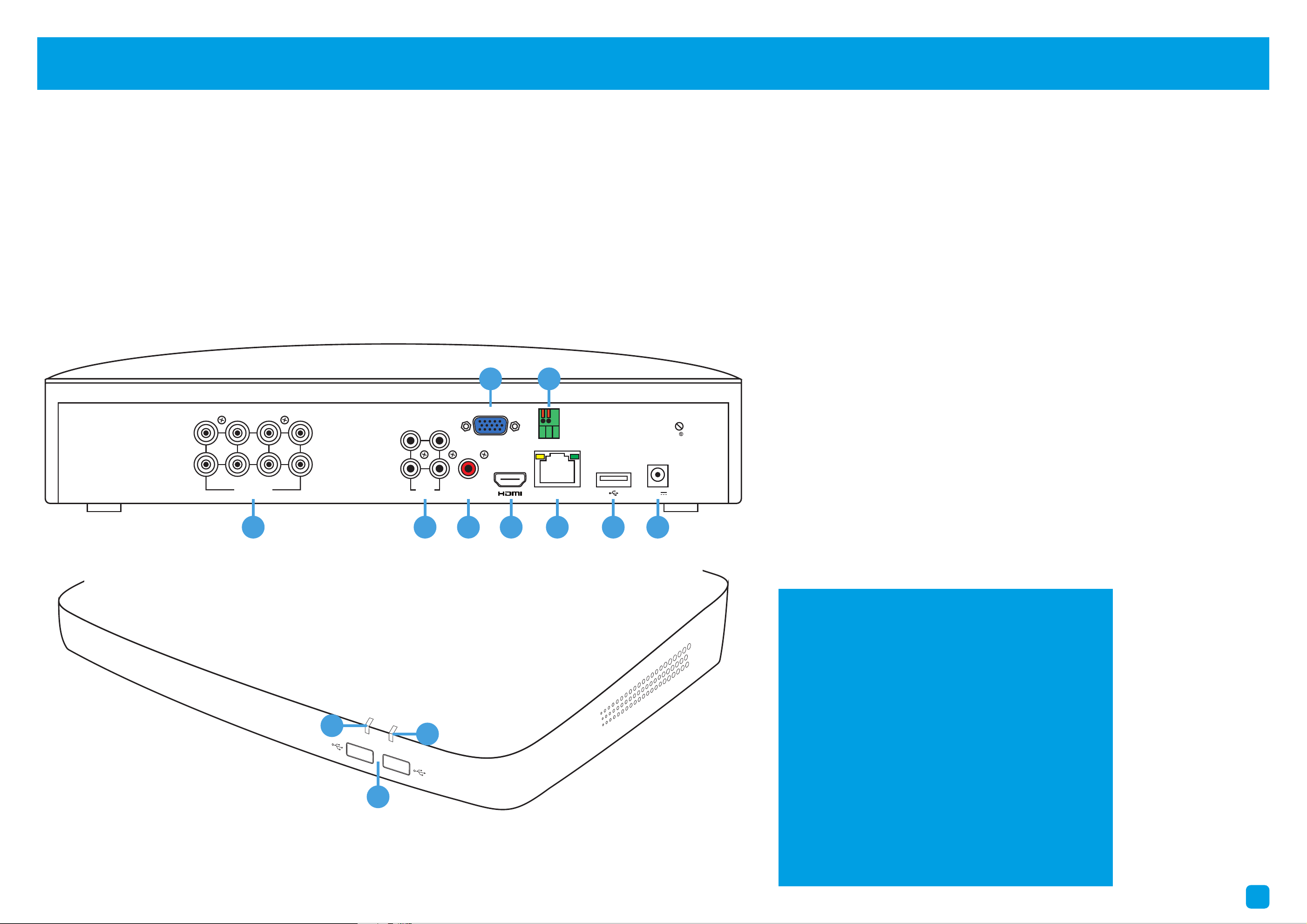
1. Camera Inputs: Connect your cameras here. Twist the
video connection to lock it in place.
2. Audio Input/s: For connecting a microphone to record
audio (the microphone must have its own power source).
3. Audio Output: For connecting to a stereo or amplifier. This
is not required when using the HDMI port.
4. VGA Port: Connect this to your monitor with a VGA input
(VGA cable not supplied). This is not required when using
the HDMI port.
5. HDMI Port: Connect this to your TV with a HDMI input
(HDMI cable supplied).
6. PTZ Port: For connecting RS-485 compatible devices.
7. Ethernet Port: Connect this to your router so your DVR
can connect to the internet (Ethernet cable supplied).
8. USB Port (8 & 16 Channel models only): This port is USB
3.0 compatible. If you have a USB 3.0 flash drive, connect it
here to copy events or to perform a firmware upgrade.
9. Power Port: Connect the 12V power adapter here.
10. Power LED: Indicates your DVR has power.
11. Hard Drive LED: Flashes when the hard drive is active.
12. USB Ports: Connect your mouse to one of the ports.
Connect a USB flash drive to the other port.
Deutsch
1. Schließen Sie die Videoausgangs- und
Stromeingangsanschlüsse der Kamera an die
Anschlüsse am Video- und Netzkabel an.
2. Schließen Sie den Stromteiler an das andere
Ende des Video- und Netzkabels an.
3. Schließen Sie das andere Ende des Netzteilers
an das Netzteil an und schließen Sie dann das
Netzteil an eine Ersatzsteckdose an.
4. Schließen Sie den Videoausgang am Video- und
Netzkabel an jeden Kameraeingang Ihres DVR an.
Italiano
1. Collegare l’uscita video e le connessioni di
ingresso di alimentazione sulla fotocamera alle
connessioni sul cavo video e di alimentazione.
2. Collegare il divisore di alimentazione all’altra
estremità del cavo di alimentazione e video.
3. Collegare l’altra estremità del divisore di
alimentazione all’adattatore di alimentazione,
quindi collegare alla presa di corrente.
4. Collegare l’uscita video sul cavo video e di
alimentazione a ciascun ingresso della telecamera.
1. Camera Inputs
2. Audio Inputs
3. Audio Output
4. VGA Port
5. HDMI Port
6. PTZ Port
7. Ethernet Port
8. USB Port
9. Power Port
10. Power LED
11. Hard Drive LED
12. USB Port/s
1. Keep your DVR free from obstructions to
maintain optimal operating temperature.
1. Halten Sie Ihren DVR frei von Hindernissen,
um eine optimale Temperatur zu halten.
1. Mantenere il DVR libero da ostacoli per
mantenere una temperatura ottimale.
2. Some of the connections illustrated may
differ with your DVR model.
2. Einige der Verbindungen können sich von
Ihrem DVR-Modell unterscheiden.
2. Alcune delle connessioni illustrate possono
differire con il modello DVR.
This installation guide will assist you on getting your DVR up and running as soon as possible. To make sure nothing was
damaged during shipping, we recommend that you connect everything and try it before you do a permanent installation.
Deutsch: Dieser Leitfaden wird Ihnen helfen, Ihren DVR so schnell wie möglich laufen zu lassen. Es wird empfohlen, alles
zu verbinden und auszuprobieren, bevor Sie eine permanente Installation durchführen.
Italiano: Questa guida vi aiuterà a ottenere il vostro DVR in esecuzione il più presto possibile. Si consiglia di collegare tutto
e provare prima di fare un’installazione permanente.
Step/Schritt/Passo: 1 (8 Channel model illustration shown)
Step/Schritt/Passo: 2
FCC Warning Statement:
This device complies with part 15 of the FCC Rules.
Operation is subject to the following two conditions: (1)
This device may not cause harmful interference and (2) this
device must accept any interference received, including
interference that may cause undesired operation.
Battery Safety Information:
This product contains a coin/button cell battery. If the cell
battery is swallowed, it can cause severe internal burns
and can lead to death. Keep away from babies and small
children at all times.
• If the battery is swallowed or placed inside any part of
the body, immediately seek medical help
• Risk of explosion if incorrect battery is used
• Dispose of used battery properly
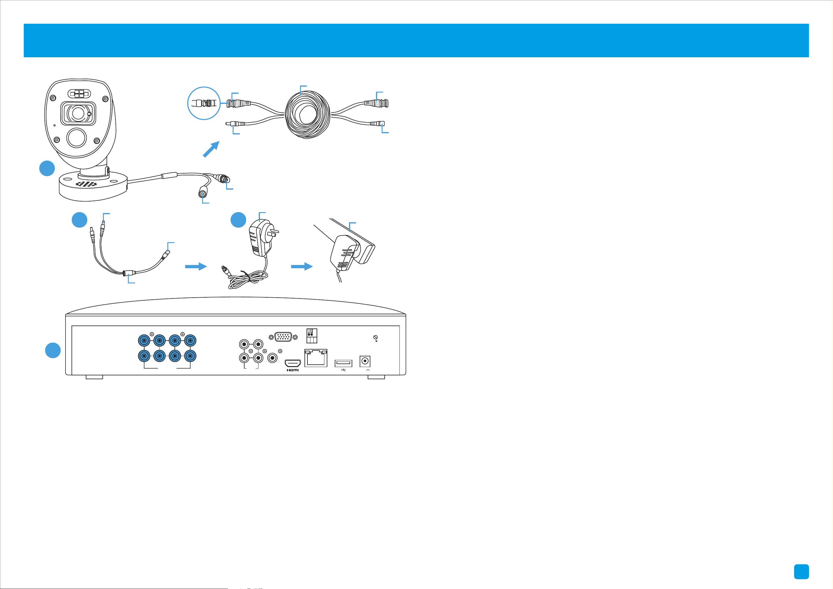
Step/Schritt/Passo: 3 (8 Channel model illustration shown)
1. Connect the video output and power input connections on the
camera to the corresponding connections on the video & power cable.
2. Connect the power splitter to the other end of the video & power
cable. This will power multiple cameras using a single power adapter.
3. Connect the other end of the power splitter to the power adapter
then connect the power adapter to a spare power outlet.
4. Connect the video output on the video & power cable to each camera
input on your DVR. Twist the connection to lock it in place.
HDD
PWR
LANLAN
VGAVGA
7 5 3 1
8 6 4 2
VIDEO INPUTVIDEO INPUT
AUDIO
OUTPUT
AUDIO
OUTPUT
AUDIO
INPUT
AUDIO
INPUT
3 1
4 2
12V12V
RS485RS485
10
11
12
1 2 3
4
5
6
7 8 9
2 3
Power Input
Video Output
1
Twist to lock
connectors
Video Input
Video & Power Cable
Connect this to your DVR
Power Splitter
connects here
Power Output
Power Adapter
connects here
Power Splitter
Power Adapter
Video & Power Cable
connects here
Connect to a spare
power outlet
LANLAN
VGAVGA
7 5 3 1
8 6 4 2
VIDEO INPUTVIDEO INPUT
AUDIO
OUTPUT
AUDIO
OUTPUT
AUDIO
INPUT
AUDIO
INPUT
3 1
4 2
12V12V
RS485RS485
4
First!
Ersten!
Prima!
2
Hardware Installation Guide
Hardware-Installationshandbuch
Guida all’installazione dell’hardware
To start using your DVR, you need the following:
1. A high-definition TV capable of displaying 720p or 1080p video.
2. A router with a broadband internet connection.
3. A mobile device (Android or iOS) to download the mobile app.
Deutsch
Um Ihren DVR zu verwenden, benötigen Sie Folgendes:
1. Ein High-Definition-TV in der Lage, 720p oder 1080p Video anzuzeigen.
2. Ein Router mit Breitband-Internetverbindung.
3. Ein mobiles Gerät (Android oder iOS), um die mobile App herunterzuladen.
Italiano
Per iniziare a utilizzare il DVR, è necessario quanto segue:
1. Un televisore ad alta definizione in grado di visualizzare video 720p o
1080p.
2. Un router con una connessione Internet a banda larga.
3. Un dispositivo mobile (Android o iOS) per scaricare l’app mobile.
QH_4816CH_4680_5680_4KRLEDEI_130520 | © Swann 2020
3 4
1. Camera Inputs: Connect your cameras here. Twist the
video connection to lock it in place.
2. Audio Input/s: For connecting a microphone to record
audio (the microphone must have its own power source).
3. Audio Output: For connecting to a stereo or amplifier. This
is not required when using the HDMI port.
4. VGA Port: Connect this to your monitor with a VGA input
(VGA cable not supplied). This is not required when using
the HDMI port.
5. HDMI Port: Connect this to your TV with a HDMI input
(HDMI cable supplied).
6. PTZ Port: For connecting RS-485 compatible devices.
7. Ethernet Port: Connect this to your router so your DVR
can connect to the internet (Ethernet cable supplied).
8. USB Port (8 & 16 Channel models only): This port is USB
3.0 compatible. If you have a USB 3.0 flash drive, connect it
here to copy events or to perform a firmware upgrade.
9. Power Port: Connect the 12V power adapter here.
10. Power LED: Indicates your DVR has power.
11. Hard Drive LED: Flashes when the hard drive is active.
12. USB Ports: Connect your mouse to one of the ports.
Connect a USB flash drive to the other port.
Deutsch
1. Schließen Sie die Videoausgangs- und
Stromeingangsanschlüsse der Kamera an die
Anschlüsse am Video- und Netzkabel an.
2. Schließen Sie den Stromteiler an das andere
Ende des Video- und Netzkabels an.
3. Schließen Sie das andere Ende des Netzteilers
an das Netzteil an und schließen Sie dann das
Netzteil an eine Ersatzsteckdose an.
4. Schließen Sie den Videoausgang am Video- und
Netzkabel an jeden Kameraeingang Ihres DVR an.
Italiano
1. Collegare l’uscita video e le connessioni di
ingresso di alimentazione sulla fotocamera alle
connessioni sul cavo video e di alimentazione.
2. Collegare il divisore di alimentazione all’altra
estremità del cavo di alimentazione e video.
3. Collegare l’altra estremità del divisore di
alimentazione all’adattatore di alimentazione,
quindi collegare alla presa di corrente.
4. Collegare l’uscita video sul cavo video e di
alimentazione a ciascun ingresso della telecamera.
1. Camera Inputs
2. Audio Inputs
3. Audio Output
4. VGA Port
5. HDMI Port
6. PTZ Port
7. Ethernet Port
8. USB Port
9. Power Port
10. Power LED
11. Hard Drive LED
12. USB Port/s
1. Keep your DVR free from obstructions to
maintain optimal operating temperature.
1. Halten Sie Ihren DVR frei von Hindernissen,
um eine optimale Temperatur zu halten.
1. Mantenere il DVR libero da ostacoli per
mantenere una temperatura ottimale.
2. Some of the connections illustrated may
differ with your DVR model.
2. Einige der Verbindungen können sich von
Ihrem DVR-Modell unterscheiden.
2. Alcune delle connessioni illustrate possono
differire con il modello DVR.
This installation guide will assist you on getting your DVR up and running as soon as possible. To make sure nothing was
damaged during shipping, we recommend that you connect everything and try it before you do a permanent installation.
Deutsch: Dieser Leitfaden wird Ihnen helfen, Ihren DVR so schnell wie möglich laufen zu lassen. Es wird empfohlen, alles
zu verbinden und auszuprobieren, bevor Sie eine permanente Installation durchführen.
Italiano: Questa guida vi aiuterà a ottenere il vostro DVR in esecuzione il più presto possibile. Si consiglia di collegare tutto
e provare prima di fare un’installazione permanente.
Step/Schritt/Passo: 1 (8 Channel model illustration shown)
Step/Schritt/Passo: 2
FCC Warning Statement:
This device complies with part 15 of the FCC Rules.
Operation is subject to the following two conditions: (1)
This device may not cause harmful interference and (2) this
device must accept any interference received, including
interference that may cause undesired operation.
Battery Safety Information:
This product contains a coin/button cell battery. If the cell
battery is swallowed, it can cause severe internal burns
and can lead to death. Keep away from babies and small
children at all times.
• If the battery is swallowed or placed inside any part of
the body, immediately seek medical help
• Risk of explosion if incorrect battery is used
• Dispose of used battery properly
Step/Schritt/Passo: 3 (8 Channel model illustration shown)
1. Connect the video output and power input connections on the
camera to the corresponding connections on the video & power cable.
2. Connect the power splitter to the other end of the video & power
cable. This will power multiple cameras using a single power adapter.
3. Connect the other end of the power splitter to the power adapter
then connect the power adapter to a spare power outlet.
4. Connect the video output on the video & power cable to each camera
input on your DVR. Twist the connection to lock it in place.
HDD
PWR
LANLAN
VGAVGA
7 5 3 1
8 6 4 2
VIDEO INPUTVIDEO INPUT
AUDIO
OUTPUT
AUDIO
OUTPUT
AUDIO
INPUT
AUDIO
INPUT
3 1
4 2
12V12V
RS485RS485
10
11
12
1 2 3
4
5
6
7 8 9
2 3
Power Input
Video Output
1
Twist to lock
connectors
Video Input
Video & Power Cable
Connect this to your DVR
Power Splitter
connects here
Power Output
Power Adapter
connects here
Power Splitter
Power Adapter
Video & Power Cable
connects here
Connect to a spare
power outlet
LANLAN
VGAVGA
7 5 3 1
8 6 4 2
VIDEO INPUTVIDEO INPUT
AUDIO
OUTPUT
AUDIO
OUTPUT
AUDIO
INPUT
AUDIO
INPUT
3 1
4 2
12V12V
RS485RS485
4
First!
Ersten!
Prima!
5 6
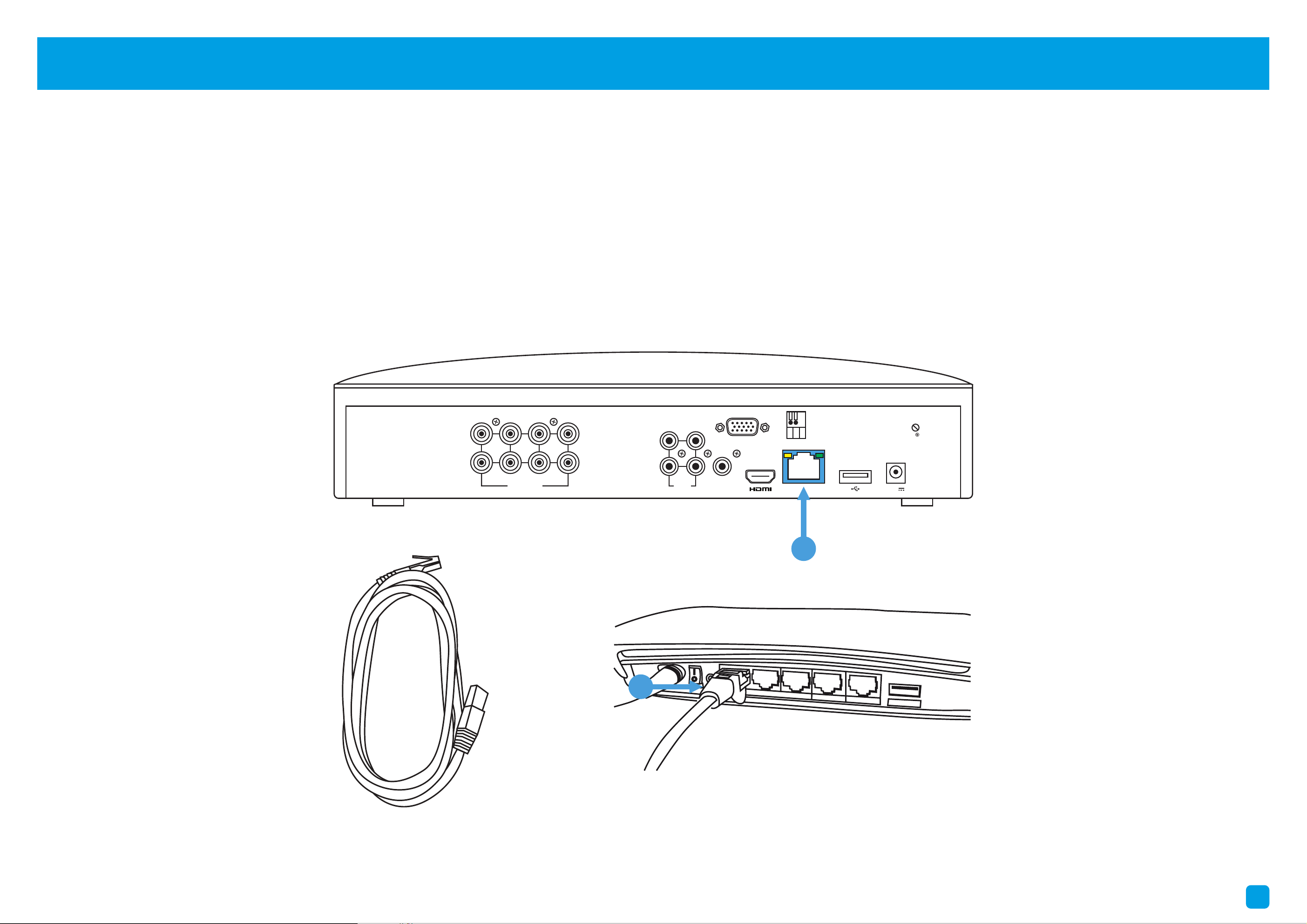
Connect to your Home Network: Connect the supplied Ethernet cable to the Ethernet port (1) on your DVR then connect
the other end to a spare port (2) on your router or Wi-Fi access point. Don’t proceed to the next step until this is done.
Verbinden Sie sich mit Ihrem Heimnetzwerk: Schließen Sie das mitgelieferte Ethernet-Kabel an den Ethernet-Port (1)
Ihres DVR an und verbinden Sie dann das andere Ende mit einem Ersatzport (2) an Ihrem Router oder WLAN-Zugriffspunkt.
Connettersi alla rete domestica: Collegare il cavo Ethernet fornito alla porta Ethernet (1) sul DVR, quindi collegare l’altra
estremità a una porta di riserva (2) sul router o sul punto di accesso Wi-Fi.
7 8
2
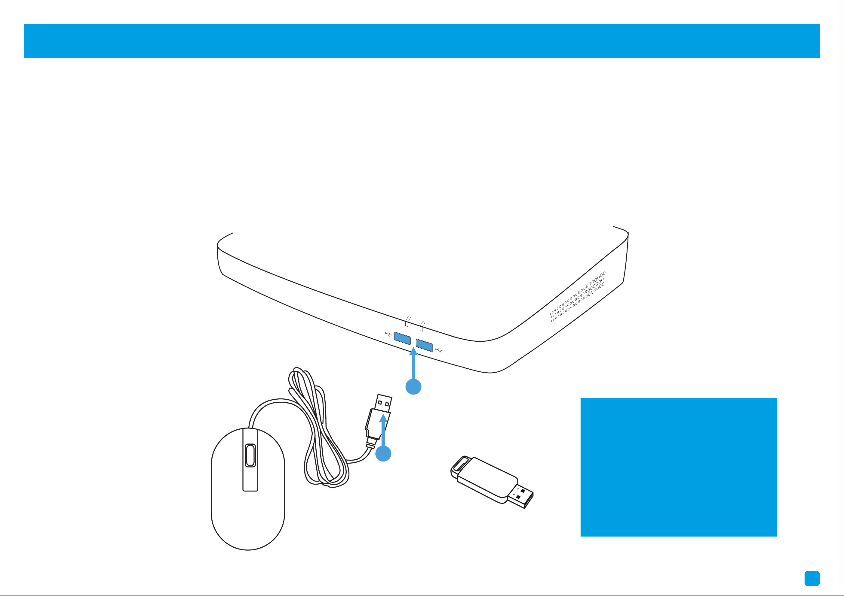
Connect your Mouse: Connect the supplied mouse (1) to one of the available USB ports (2) located at the front. To copy
events and to perform a firmware upgrade, connect a USB flash drive (not supplied) to the other port.
Verbinden Sie die Maus: Schließen Sie die Maus (1) an einen der verfügbaren USB-Anschlüsse (2) an der Vorderseite an.
Schließen Sie ein USB-Flashlaufwerk an den anderen Port an, um Ereignisse zu kopieren.
Collegare il mouse: Collegare il mouse (1) a una delle porte USB disponibili (2) nella parte anteriore. Collegare un’unità
flash USB all’altra porta per copiare gli eventi.
HDMI IN 1
HDMI IN 2
2
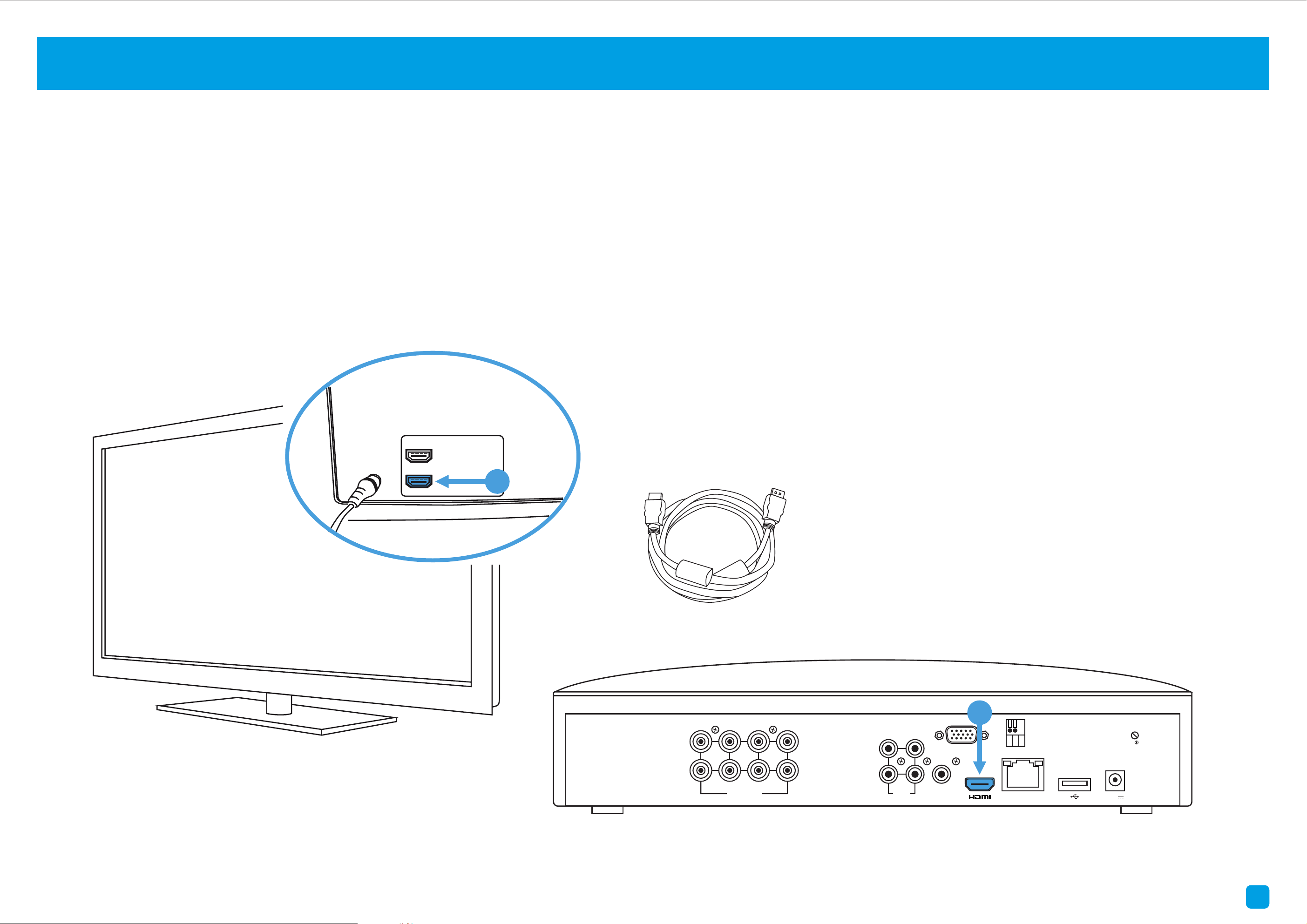
Connect to your TV: Connect the supplied HDMI cable to the HDMI port (1) then connect the other end to a spare HDMI
input (2) on your TV. Press the A/V button on your TV’s remote to select the HDMI input.
Anschließen an Ihren Fernseher: Schließen Sie das HDMI-Kabel an den HDMI-Anschluss (1) an und schließen Sie dann
das andere Ende an einen Ersatz-HDMI-Eingang (2) an Ihrem Fernseher an.
Collegare alla TV: Collegare il cavo HDMI alla porta HDMI (1) quindi collegare l’altra estremità a un ingresso HDMI di
riserva (2) sul televisore. Premere il pulsante A/V sul telecomando del televisore per selezionare l’ingresso HDMI.
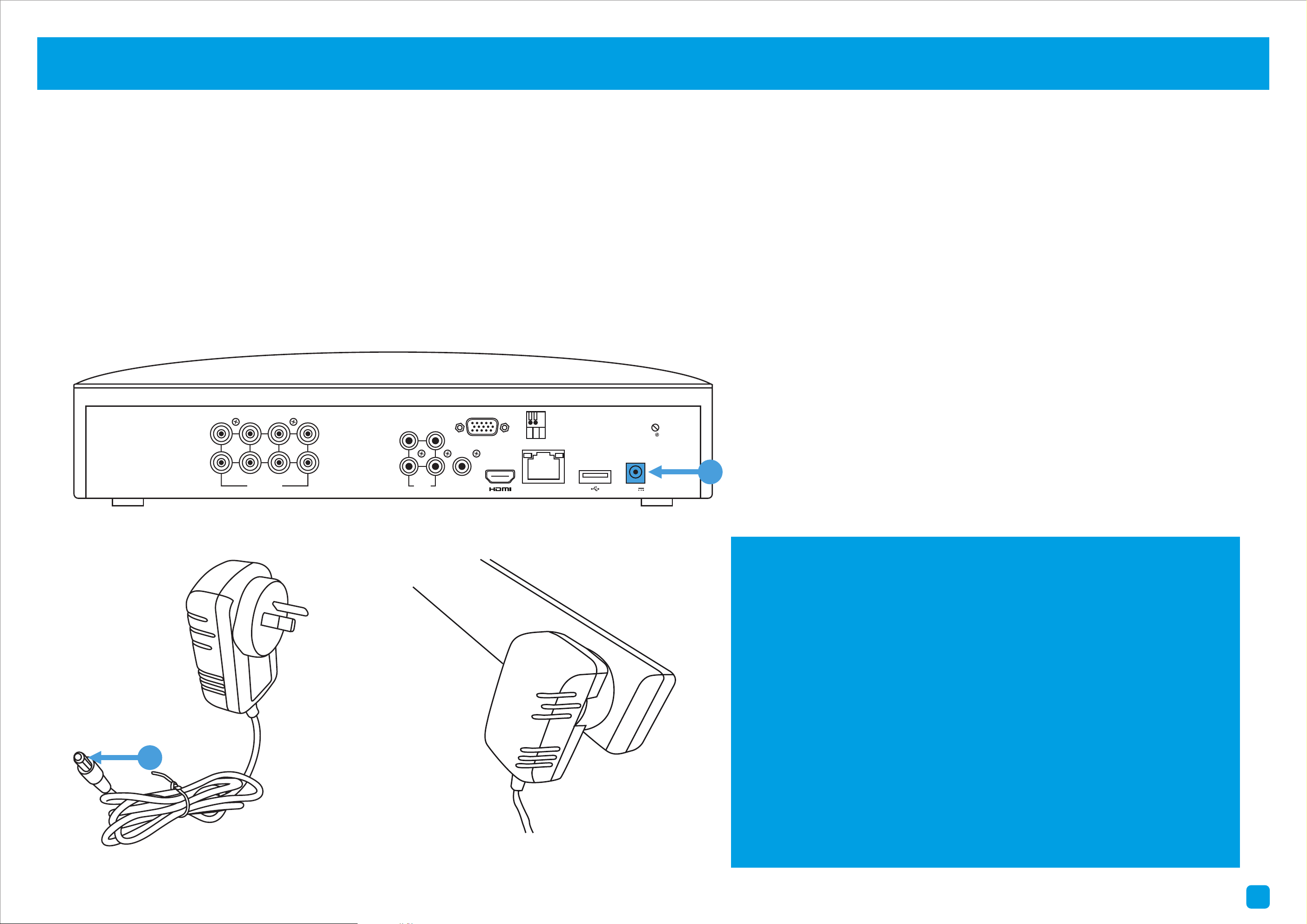
Connect your Power Adapter: Connect the supplied power adapter’s power connection (1) to the power input (2) on your
DVR first (to minimize sparking). Connect the power adapter to a power outlet to supply power.
Schließen Sie Ihren Netzadapter an: Schließen Sie den Netzanschluss des mitgelieferten Netzteils (1) an den Stromeingang
(2) Ihres DVR an (um die Funkenflugzufuhr zu minimieren).
Collegare prima l’adattatore di alimentazione: Collegare la connessione di alimentazione dell’adattatore di alimentazione
fornito (1) all’ingresso di alimentazione (2) sul DVR (per ridurre al minimo la scintilla).
1
You will see the Startup Wizard displayed. Follow
the “Startup Wizard Quick Start Guide” (the red
coloured guide) to configure and setup your DVR.
Der Start-Assistent wird angezeigt. Folgen Sie
der “Start assistent Schnellstartanleitung”
(rote Anleitung), um Ihren DVR zu konfigurieren.
Verrà visualizzata la procedura guidata di avvio.
Seguire la “Guida rapida guidata” (la guida di
colore rosso) per configurare e configurare il
DVR.
Step/Schritt/Passo: 4 (8 Channel model illustration shown) Step/Schritt/Passo: 5
Step/Schritt/Passo: 6 (8 Channel model illustration shown) Step/Schritt/Passo: 7 (8 Channel model illustration shown)
LANLAN
VGAVGA
7 5 3 1
8 6 4 2
VIDEO INPUTVIDEO INPUT
AUDIO
OUTPUT
AUDIO
OUTPUT
AUDIO
INPUT
AUDIO
INPUT
3 1
4 2
12V12V
RS485RS485
1
LANLAN
VGAVGA
7 5 3 1
8 6 4 2
VIDEO INPUTVIDEO INPUT
AUDIO
OUTPUT
AUDIO
OUTPUT
AUDIO
INPUT
AUDIO
INPUT
3 1
4 2
12V12V
RS485RS485
1
LANLAN
VGAVGA
7 5 3 1
8 6 4 2
VIDEO INPUTVIDEO INPUT
AUDIO
OUTPUT
AUDIO
OUTPUT
AUDIO
INPUT
AUDIO
INPUT
3 1
4 2
12V12V
RS485RS485
2
HDD
PWR
2
1
Compatible with USB flash
drives up to 128GB.
Kompatibel mit USB-Flash-
Laufwerken bis zu 128 GB.
Compatibile con unità flash
USB fino a 128 GB.
5 6
Connect to your Home Network: Connect the supplied Ethernet cable to the Ethernet port (1) on your DVR then connect
the other end to a spare port (2) on your router or Wi-Fi access point. Don’t proceed to the next step until this is done.
Verbinden Sie sich mit Ihrem Heimnetzwerk: Schließen Sie das mitgelieferte Ethernet-Kabel an den Ethernet-Port (1)
Ihres DVR an und verbinden Sie dann das andere Ende mit einem Ersatzport (2) an Ihrem Router oder WLAN-Zugriffspunkt.
Connettersi alla rete domestica: Collegare il cavo Ethernet fornito alla porta Ethernet (1) sul DVR, quindi collegare l’altra
estremità a una porta di riserva (2) sul router o sul punto di accesso Wi-Fi.
7 8
2
Connect your Mouse: Connect the supplied mouse (1) to one of the available USB ports (2) located at the front. To copy
events and to perform a firmware upgrade, connect a USB flash drive (not supplied) to the other port.
Verbinden Sie die Maus: Schließen Sie die Maus (1) an einen der verfügbaren USB-Anschlüsse (2) an der Vorderseite an.
Schließen Sie ein USB-Flashlaufwerk an den anderen Port an, um Ereignisse zu kopieren.
Collegare il mouse: Collegare il mouse (1) a una delle porte USB disponibili (2) nella parte anteriore. Collegare un’unità
flash USB all’altra porta per copiare gli eventi.
HDMI IN 1
HDMI IN 2
2
Connect to your TV: Connect the supplied HDMI cable to the HDMI port (1) then connect the other end to a spare HDMI
input (2) on your TV. Press the A/V button on your TV’s remote to select the HDMI input.
Anschließen an Ihren Fernseher: Schließen Sie das HDMI-Kabel an den HDMI-Anschluss (1) an und schließen Sie dann
das andere Ende an einen Ersatz-HDMI-Eingang (2) an Ihrem Fernseher an.
Collegare alla TV: Collegare il cavo HDMI alla porta HDMI (1) quindi collegare l’altra estremità a un ingresso HDMI di
riserva (2) sul televisore. Premere il pulsante A/V sul telecomando del televisore per selezionare l’ingresso HDMI.
Connect your Power Adapter: Connect the supplied power adapter’s power connection (1) to the power input (2) on your
DVR first (to minimize sparking). Connect the power adapter to a power outlet to supply power.
Schließen Sie Ihren Netzadapter an: Schließen Sie den Netzanschluss des mitgelieferten Netzteils (1) an den Stromeingang
(2) Ihres DVR an (um die Funkenflugzufuhr zu minimieren).
Collegare prima l’adattatore di alimentazione: Collegare la connessione di alimentazione dell’adattatore di alimentazione
fornito (1) all’ingresso di alimentazione (2) sul DVR (per ridurre al minimo la scintilla).
1
You will see the Startup Wizard displayed. Follow
the “Startup Wizard Quick Start Guide” (the red
coloured guide) to configure and setup your DVR.
Der Start-Assistent wird angezeigt. Folgen Sie
der “Start assistent Schnellstartanleitung”
(rote Anleitung), um Ihren DVR zu konfigurieren.
Verrà visualizzata la procedura guidata di avvio.
Seguire la “Guida rapida guidata” (la guida di
colore rosso) per configurare e configurare il
DVR.
Step/Schritt/Passo: 4 (8 Channel model illustration shown) Step/Schritt/Passo: 5
Step/Schritt/Passo: 6 (8 Channel model illustration shown) Step/Schritt/Passo: 7 (8 Channel model illustration shown)
LANLAN
VGAVGA
7 5 3 1
8 6 4 2
VIDEO INPUTVIDEO INPUT
AUDIO
OUTPUT
AUDIO
OUTPUT
AUDIO
INPUT
AUDIO
INPUT
3 1
4 2
12V12V
RS485RS485
1
LANLAN
VGAVGA
7 5 3 1
8 6 4 2
VIDEO INPUTVIDEO INPUT
AUDIO
OUTPUT
AUDIO
OUTPUT
AUDIO
INPUT
AUDIO
INPUT
3 1
4 2
12V12V
RS485RS485
1
LANLAN
VGAVGA
7 5 3 1
8 6 4 2
VIDEO INPUTVIDEO INPUT
AUDIO
OUTPUT
AUDIO
OUTPUT
AUDIO
INPUT
AUDIO
INPUT
3 1
4 2
12V12V
RS485RS485
2
HDD
PWR
2
1
Compatible with USB flash
drives up to 128GB.
Kompatibel mit USB-Flash-
Laufwerken bis zu 128 GB.
Compatibile con unità flash
USB fino a 128 GB.
