English
1
4 / 8 Channel
D1 Realtime H.264 DVR
M4-8-3000-4000-230412E
English

English
2
Before You Begin
FCC Verication
NOTE: This equipment has been tested and found to comply with the limits for Class B digital device, pursuant to part 15 of the
FCC Rules. These limits are designed to provide reasonable protection against harmful interference in a residential installation.
This equipment generates, uses and can radiate radio frequency energy and, if not installed and used in accordance with
the instructions, may cause harmful interference to radio or television reception, which can be determined by turning the
equipment o and on, the user is encouraged to try to correct the interference by one or more of the following measures:
• Reorient or relocate the receiving antenna
• Increase the separation between the equipment and the receiver
• Connect the equipment into an outlet on a circuit dierent from that to which the receiver is connected
• Consult the dealer or an experienced radio/TV technician for help
These devices comply with part 15 of the FCC Rules. Operation is subject to the following two conditions:
• These devices may not cause harmful interference, and
• These devices must accept any interference received, including interference that may cause undesired operation.
IMPORTANT NOTE:
All jurisdictions have specic laws and regulations relating to the use of cameras. Before using any camera for any purpose, it
is the buyer’s responsibility to be aware of all applicable laws and regulations that prohibit or limit the use of cameras and to
comply with the applicable laws and regulations.
FCC Regulation (for USA): Prohibition against eavesdropping
Except for the operations of law enforcement ocers conducted under lawful authority, no person shall use, either directly
or indirectly, a device operated pursuant to the provisions of this Part for the purpose of overhearing or recording the private
conversations of others unless such use is authorized by all of the parties engaging in the conversation.
WARNING
Modications not approved by the party responsible for compliance could void user’s authority to operate the equipment.
IMPORTANT SAFETY INSTRUCTIONS
• Make sure product is xed correctly and stable if fastened in place
• Do not operate if wires and terminals are exposed
• Do not cover vents on the side or back of the DVR and allow adequate space for ventilation
DEFAULT PASSWORD INFORMATION
To ensure your privacy, this DVR supports password protection.
The default, all-access username is “admin”. If the DVR asks you to log in before you’ve set a password, enter admin as your
username and leave the password blank. This will give you access to all areas of the DVR.
The password function is disabled by default. However, if you’re asked for a password, the default is “12345”.
To ensure your ongoing privacy, we strongly recommend setting a password as soon as possible. Choose something that
you’ll remember, but that others would be unlikely to guess.
If you do manage to lock yourself out of the DVR, you’ll need to contact us at the Swann Technical Support Telephone Helpdesk
- the number is on the back cover.

English
3
Contents
Before You Begin 2
Contents 3
Layout of the DVR 6
Layout of Remote Control 7
Camera: Display 8
Camera: Output 9
Recording: Encode 10
Recording: Option 11
Recording: Schedule 12
Recording: Option 13
Search: Playback 14
Search: Backup, Event & Log Search 15
The Playback Interface 16
Network: General 18
Network: Advanced 19
Network: Advanced: DDNS 20
Network: Advanced: NTP 20
Network: Advanced: Email Settings 21
Network: Advanced: IP Filter 22
Network: Network Status 22
Alarm: Motion 24
Alarm: Motion Detection Conguration 25
Alarm: Video Loss & Exception 26
Alarm: Video Loss 27
Alarm: Exception 27
Alarm: Action 27
Device: HDD 28
Device: S.M.A.R.T. 28
Device: PTZ 29
System: General 31
System: User 32
System: System Information 33
System: Device State 33
System: Maintenance 34
Remote Access: Installing MyDVR 36
Remote Access: Login 37
MyDVR: Interface 38
MyDVR: Local Conguration 39
MyDVR: Quick Cong 40
MyDVR: Settings 41
Warranty Information 43
Technical Support Rear Cover

English
4
Introduction
Basic DVR Operation
Congratuations on your purchase of this Swann DVR. You’ve
made a ne choice for keeping a watchful eye over your home
or business. Let’s take a moment to talk about some of the
features this DVR oers, and how to get the most out of them.
Multi-Channel Recording Solution
The DVR records 4 or 8 channels (depending on your model)
at “D1” resolution.
What’s this “D1”?
D1 is a (slightly inaccurate) term for a certain resolution of
video which is now often called “broadcast quality”. We like to
think about it as being about the quality of a DVD movie.
Some savvy nerds will know where the term came from and
why it’s not quite correct, but it’s become a standard term in
the CCTV industry, so we use it here.
Fast and Easy Networking
Now supporting UPnP, networking your DVR has never been
easier. For the majority of networks, it’s almost plug-and-play.
Users with more complex network congurations might
have to adjust some settings (see “Network: General” on page
19 for more about networking) to get everything running
smoothly.
Easy Setup using your PC (Recommended)
The remote access and conguration features of the included
MyDVR software are so powerful that (technically speaking)
you don’t even have to touch the DVR to operate it (except for
plugging things in, of course).
If you connect the DVR to your network and install the MyDVR
software to a compatible PC on the same network, you can
complete the DVR setup procedure there, as well as stream
images from the DVR straight to your PC monitor.
Requirements:
A compatible computer connected to the same network
as the DVR. The network must support DHCP and UPnP.
• Connect your DVR to your cameras, power and a network
as shown on page 6.
• Ensure that your network uses DHCP addressing, and
supports UPnP (Universal Plug and Play - see page 19).
• Install the MyDVR software on a computer connected to
the same network as the DVR (see page 35).
• Login to your DVR, view images and congure settings
(see page 36 onwards for more details).
The USB Mouse (Recommended)
The easiest way to operate the DVR is to use the included USB
optical mouse - we put together the look and feel of the menu
system specically for mouse-friendly navigation.
The controls are pretty easy to remember - heck, there are only
two buttons. It couldn’t be simpler.
Left click:
• Selects an item or conrms a choice.
Right click:
• Opens the menu bar from the live viewing screen.
• Returns one “step” from a submenu.
• Opens a context menu in some settings screens.
The Scroll Wheel:
• Can be used to adjust the values of sliders and scales
when highlighted by the moust.
Of course, you don’t have to use the mouse.
The Front Panel
The buttons on the front panel are adequate for operating the
DVR, but they’re hardly ideal for ongoing use.
Between Menu, Select and the D-pad (directional pad) you can
navigate through all the DVR’s menus and congure almost
any setting. It’s a little clunkier than the mouse and it’s not as
quick and easy, but it does save a little space - and you don’t
need to nd the remote!
The Remote Control
The remote control has all the buttons that the front panel
does, plus some others. It operates like a remote control for
a DVD player or similar - it’s hardly a high-tech gadget these
days but it does get the job done!
A full rundown of the remote control and its various functions
can be found on page 8.

English
5
English
6
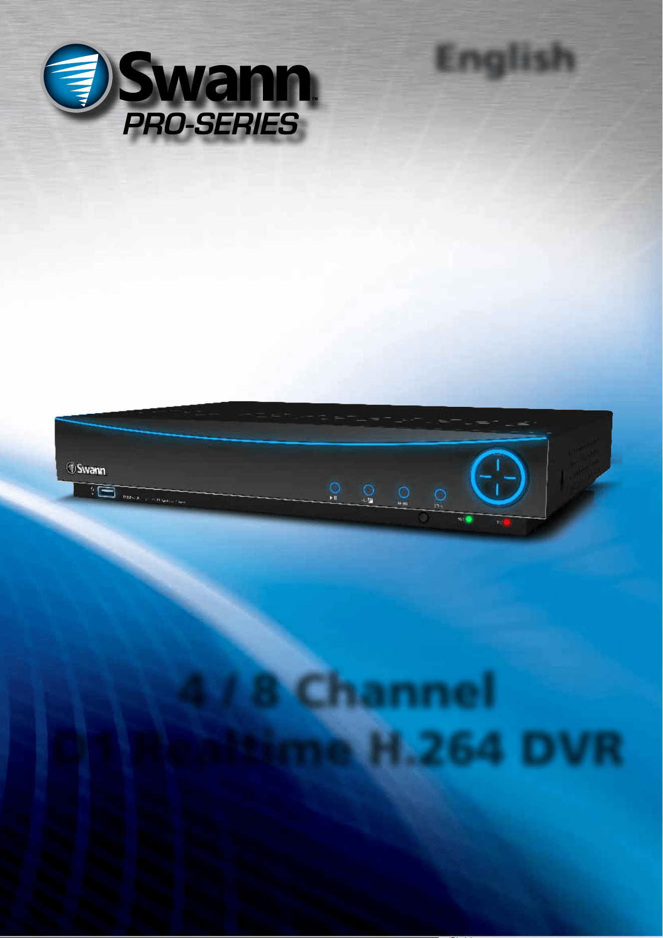
Connect the BNC outputs from
your cameras into the yellow BNC
inputs on the rear of the DVR.
Connect your cameras to
power, using the a power-
splitter (if included).
Connect the DC12V
Output from the
power supply to
the power input.
Connect the power
supply to a wall
outlet.
Connect the mouse
to the USB2.0 port.
If you’ve got a monitor with VGA
but not HDMI, connect it to the VGA
output on the DVR.
If you’ve got a TV or monitor
with HDMI in, connect to
the HDMI port on the DVR.
Connect an ethernet
cable from the LAN port
on the DVR to a spare
port on your router.
Connection Diagram
English
7
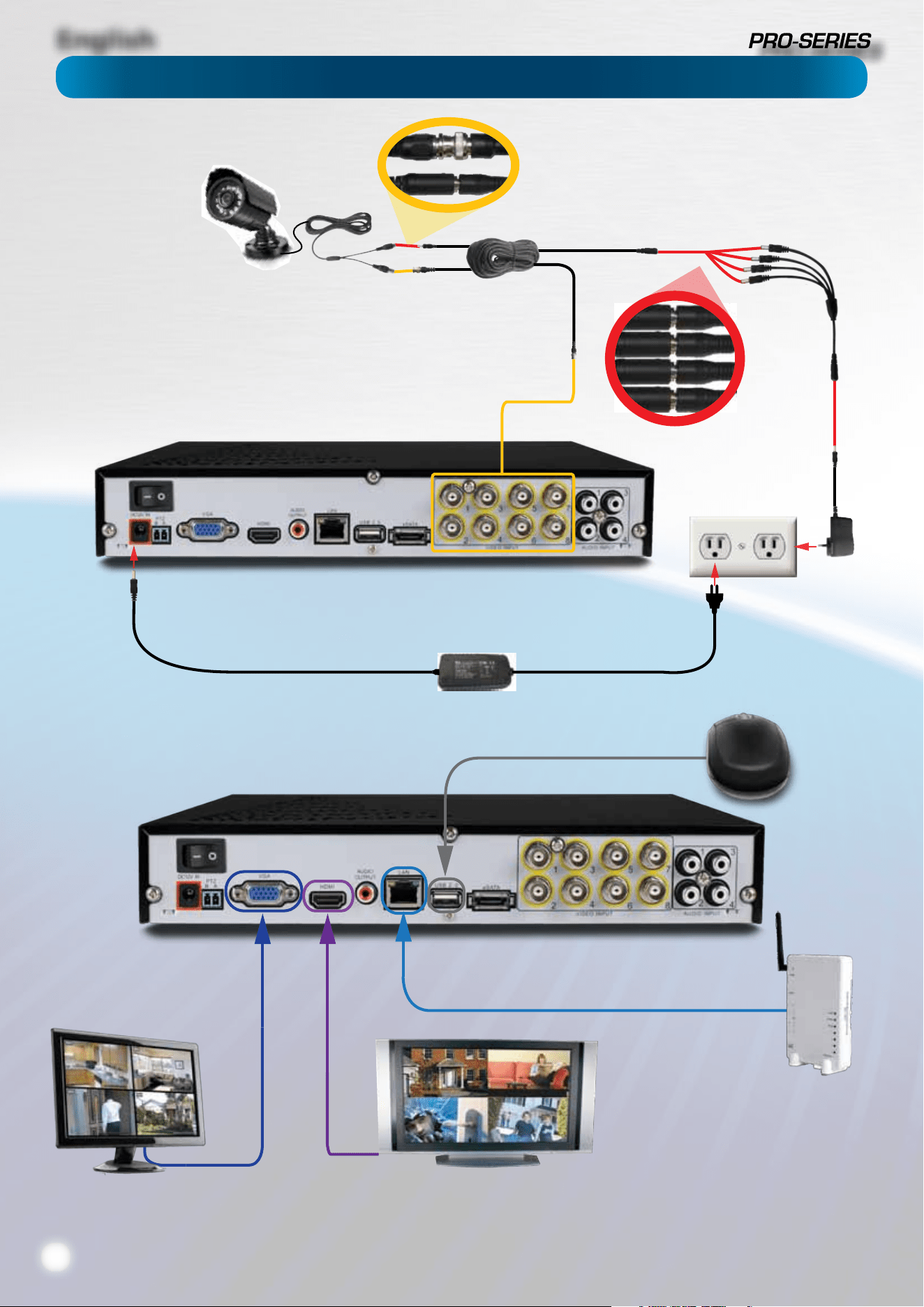
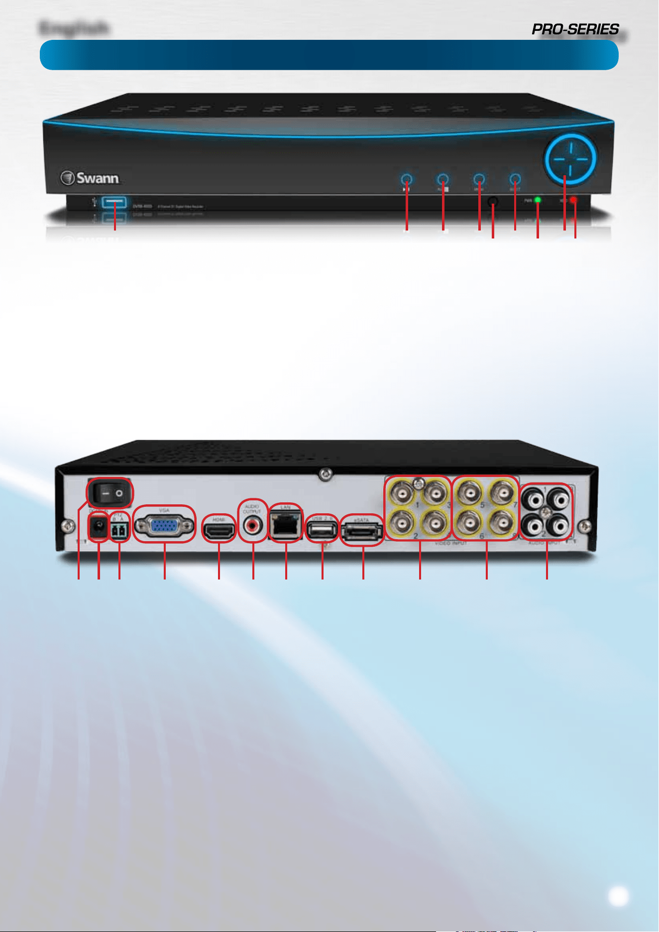
Layout of the DVR
1) Video Inputs 1 - 4: These are your primary video inputs.
Each accepts a standard composite video signal and connects
via a BNC connector.
The channels are labeled by number in the same order as they
will appear on your DVR’s interface.
2) Video Inputs 5 - 8: As 1) but apply to the 8-channel model
only.
3) Audio Inputs: These will accept a standard line-level signal
(<1V).
4) HDMI Output: The primary output of the DVR. For the
highest possible video output quality, we suggest using this
output.
• For best results, use a monitor/television capable of
displaying Full HD 1080p.
• Note that many televisions which can display 1080p
signals are not actually Full HD. These kinds of televisions
downscale a 1080p signal to the resolution of the screen.
For the best possible image, use a television/monitor
which can display 1920 x 1080 or higher.
5) VGA Output: For connecting a television or PC monitor
with a VGA input.
6) Audio Output: A standard line-level audio output.
7) Network Port: Where you can connect the DVR to a
network, typically directly into the router or network switch.
8) USB 2.0 Port: For connecting a USB mouse or a USB storage
device. We suggest connecting USB storage to the USB port
on the front of the DVR, and using the rear port for the mouse.
9) eSATA Port: To connect an external hard drive, to which
you can backup footage.
10) PTZ (RS485) Port: To connect the RS485 cables to control
a PTZ (pan, tilt, zoom) device to the DVR.
11) DC 12V Power Input: Where you connect the included DC
12V power adapter. Use only the supplied power adapter with
the DVR, and use the power adapter only with the DVR.
12) Power Switch: Master ON/OFF switch.
1) USB 2.0 Port: For connecting USB external storage to the
DVR for backup, or for applying new rmware.
2) Play/Pause: Opens the playback interface from the live
viewing mode. Pauses playback or resumes playback from
paused.
3) Quad (4ch)/All (8ch): Enters split-screen view, where the
screen shows one, four (“quad” mode 2 x 2) or eight (8ch only - 3
x 3 with one space blank) video feeds at once.
4) Menu: Opens the DVR’s menu, or goes back one step from
a submenu.
5) Select: As the name suggests, it selects an option or item
from a menu.
6) D-pad: For navigating around menus when you’re not using
the mouse. (Why aren’t you using the mouse? It’s awesome.)
7) IR Receiver: Where the DVR will pick up signals from the IR
remote control. If this is obstructed, the remote will not work.
8) Power LED: Will be lit whenever the DVR is supplied power
and turned on.
9) HDD LED: Will ash whenever the DVR is writing to/reading
from the installed hard drive.
21 3 4
7
5
8
6
9
1112 10 5 4 6 7 8 9 1 2 3

English
8
Layout of Remote Control
Installation Guidelines
1
3
4
6
9
10
11
12
14
13
10
8
7
5
2
• Do not expose the DVR to moisture. Water is the arch-
enemy of electrical components and also poses a high risk
of electric shock.
• Avoid dusty locations. Dust has a tendency to build up
inside the DVR case, leading to a high risk of failure or
even re.
• Only install the DVR in a well ventilated space. Like
all electronics, the circuitry and hard drive in the DVR
produce heat, and this heat needs a way out.
• Do not open the DVR case except to install/swap the
hard drive inside. There are no user serviceable parts
inside.
• Never open the case whilst the DVR is plugged in, and
never turn the DVR on whilst the case is open.
• Use only the supplied power adapter. Other adapters
may cause damage to the DVR or cause a re.
• Do not cut or modify any cable for any reason. Doing
so will void your warranty, as well as pose a great risk of
re or electrical shock.
• Do not expose the DVR to sudden bumps or shocks (for
example, being dropped). The DVR is as robust as possible,
but many of the internal components are quite fragile.
• Remember that the DVR is, in all likelihood, going to be
left on 24 hours a day, 7 days a week. Keep this in mind
when choosing a location for installation.
1) Standby: Sends the DVR into standby mode. No recording will occur while the
DVR is set to Standby.
2) Login / Lock: Locks the DVR so that it requires a password to re-open, or
initiates unlocking the DVR if it’s already locked. Only works once the password
function has been enabled and a password set (see page 32 for details).
3) Number Buttons: Can be used as shortcuts to a specic camera, and are useful
for quickly entering numerical passwords.
4) Display Mode: Enters split-screen view, where the screen shows one, four
(“quad” mode 2 x 2) or eight (8ch only - 3 x 3 with one space blank) video feeds at
once.
5) Menu: Opens the DVR’s menu.
6) PTZ: Opens the Pan/Tilt/Zoom control screen.
7) Exit: Goes back one step or level in the DVR’s menu tree.
8) Arrow Buttons: Navigates around menus or toggles through options.
9) OK: Works as the Select button does on the DVR, or as the Enter button on a
keyboard.
10) + / -: For adjusting the zoom of PTZ devices.
11) Record: Triggers manual recording mode.
12) Stop: Stops manual recording or playback in progress. Won’t have any
eect on recordings triggered by the schedule in either normal or motion-based
recording modes.
13) Mute: As the name suggests, this mutes the audio output of the DVR.
14) Playback Controls: Opens the playback interface from the live viewing
mode. Pauses, rewinds, fast forwards or or resumes playback from paused.
English
9
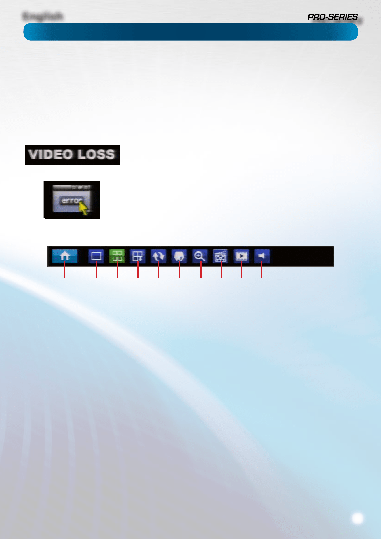
Icons & The Menu Bar
To open the Menu Bar:
• Right click with the mouse on the live viewing screen.
or
• Press the MENU button on the DVR or the remote control.
1) Menu: Opens the main menu.
2) Single Camera View: Shows images from one camera in
full-screen.
3) Multi-Camera View: Divides the screen into multiple
viewing windows, each showing images from one camera.
4) Next Camera(s): Cycles the cameras displayed in viewing
mode,
5) Start/Stop Tour: Starts or stops a PTZ tour.
6) PTZ Control: Opens the PTZ control window.
7) Digital Zoom: Increases the size of things in view, at the
cost of visual quality.
8) Manual Record: Initiates manual recording.
9) Playback: Opens the Search: Playback (page 16) menu.
10) Audio On/O: Enables or disables the audio function of
the DVR.
1 2 3 4 5 6 7 8 9 10
The camera icon indicates that this camera is currently recording. This icon will be the
same whether the recording was scheduled, initiated manually or triggered by motion
(though the motion icon will also be present if there’s motion detected).
The motion icon indicates that the DVR has detected motion coming from this camera.
It doesn’t necessarily mean it’s recording (the camera icon will be there, too, if that’s the
case!).
Video Loss indicates that the channel displaying this has lost the feed from its camera.
If you see this icon onscreen (it’ll be lurking in the lower right corner by default) it
indicates that something has gone wrong. Click the icon to access the Event Log where
you’ll get more information about exactly what has gone wrong.

English
10
Menu Bar
Display
Encode
Playback
General
Motion
HDD
General
Camera
Option
Backup
Advanced
Video Loss
S.M.A.R.T
User
Email Settings
DDNS
NTP
IP Filter
Output
Schedule
Event / Log
Status
Exceptions
PTZ
Information
Maintenance
Recording
Search
Network
Alarm
Device
System
Shut Down
Menu Layout
English
11
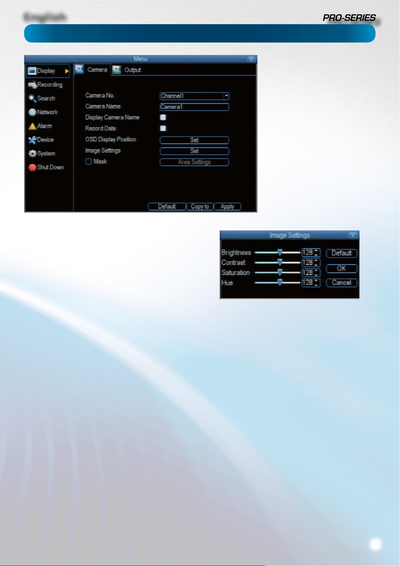
Camera: Display
Camera No.: Choose the camera / channel you want to edit
here. The Camera No is the same thing as the number written
on the rear panel next to the BNC socket used to connect the
camera.
Camera Name: Select a name for the camera you’ve selected.
By default, all channels are named as the Camera No. eld, but
this can be set to anything you’d like up to 16 characters.
Display Camera Name: When checked, the name you’ve
selected for the camera/channel will be displayed on-screen
as an overlay.
Record Date: When checked, the date (as displayed) will be
recorded directly into your videos. This can be useful, as it
creates an inseperable record of exactly when the footage was
captured.
OSD Display Position: Gives you access to a screen where
you can easily set the exact positions of any overlayed text,
such as the camera name and the date and time.
Simply select any item you want to move (such as the Channel
Name and/or the Date and Time) and click and drag it to the
position you’d like it to be.
To exit the OSD Display Position screen, right click. A context
menu will appear with two options: Save and Exit. To exit
without saving, simply choose Exit. If you want to save your
changes, choose Save rst.
Image Settings: Gives you access to image adjustment tools,
allowing you to adjust the way the DVR interprets and displays
video images. See opposite for more information.
The Image Settings you choose will aect your recorded
footage. Rather than applying the changes after the video has
been processed (like many older DVRs) the Image Settings aect
how the DVR decodes the video it is receiving from the cameras.
The upside of this is that you can use the Image Settings to
dramatically improve the quality of the images being recorded
by the DVR. This can be particularly useful for improving the
accuracy of your Motion Detection settings.
Mask: When checked, allows you to create, place and shape a
“privacy mask” which obscures the view of part of the image
on the associated channel.
Brightness: Changes how light the image appears to be.
However, it can’t make the camera see further in the dark, or
increase the clarity of an ill-lit image.
Contrast: Increases the dierence between the blackest black
and the whitest white in the image. Useful if sections of the
image “grey out” but setting the contrast too high will degrade
image quality.
Saturation: Alters how much color is displayed in the image. The
higher the saturation, the more bright and vivid colors will appear
to be. Again, setting this too high can degrade image quality.
Hue: Changes the color mix of the image (this can have
very dramatic results). It’s somewhat like moving through a
rainbow.
Remember: Your image settings will aect your recordings!
You can use the Image Settings to help ne-tune your Motion
Detection sensitivity. At night, many cameras image seems to
icker slightly, or to have increased “noise”. In video, “noise” is
random uctuations of pixels, a little like an old television that
is not set to a station, often called “static”.
By tweaking the Brightness and the Contrast you can eliminate
much of this video noise, increasing the quality of your images
and the accuracy of the Motion Detection.
The Display: Camera menu is where
you can make adjustments to how the
DVR displays the feed coming from your
cameras.
You can adjust aspects of each channel/
camera, such as:
• the camera’s name,
• which information will be displayed
on-screen, and where this
information will be displayed,
• whether information such as the
date will be recorded directly onto
your videos
• any areas of the video you want
“masked” - that is, left blank.
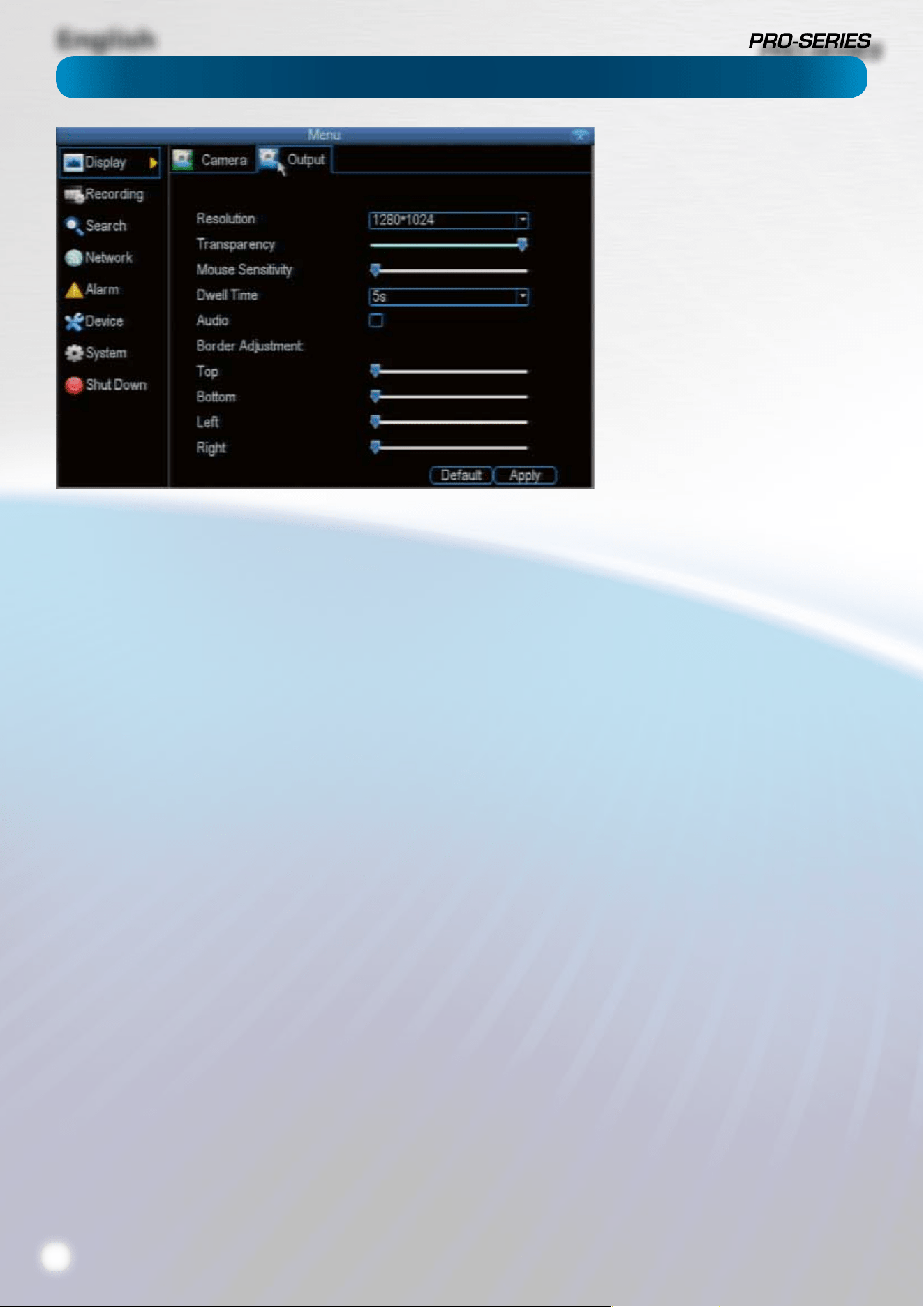
English
12
The Camera: Output menu is where
you can control how the DVR is going
to deliver an image to your television,
screen or monitor.
You’ll be able to adjust such items as:
• screen resolution and position on
your monitor
• the audio output,
• the appearance of the menus,
• the auto-sequence dwell time, and
• the sensitivity of the USB mouse.
Resolution: The number of “little dots” that make up an
image. This should be set as high as possible, but equal to
or lower than the maximum resolution your screen/monitor
can display. Things change a little depending on what kind of
monitor you’re using, and how it’s connected.
The DVR has four formats available, in two dierent aspect
ratios:
Square (4:3) - 1024 x 768 or 1280 x 1024
Widescreen (16:9) - 1280 x 720 (720p) or 1920 x 1080 (1080p)
Square Monitor via VGA: Use one of the 4:3 formats to
correctly align the DVR’s output on your screen. Using a
widescreen format will “stretch” the image vertically.
Widescreen Monitor via VGA: If possible, use the widescreen
(16:9) format. If your monitor can’t display that resolution, you
might need to enable letterboxing on your monitor and use a
4:3 format.
PC Monitor via HMDI: Choose a format appropriate for your
monitor. If it’s a widescreen, use a widescreen format. Set to
the higest option that is equal to or less than the screen’s
maximum resolution.
Widescreen Plasma/LCD HDTV via HDMI: The resolution
should be set to the maximum your television can process not
display. Typically, this will be 1080p, as even screens which
don’t have that many pixels can still display the image, just
with less detail. Check your television’s documentation to
learn this value. If your television can’t display 1080p, then use
720p instead.
Transparency: You can set the DVR’s menus to be partially
transparent (see-though) - in case you need to keep an eye on
things while adjusting settings (or it makes you feel like you’re
living in the future because it’s so tech - we don’t judge). The
best way to set this is to simply experiment over time and see
what works well for you.
Mouse Sensitivity: How sensitive the mouse will be. On
lowest, large and dramatic arm movements are required to
move the mouse but a few inches onscreen. At the other end
of the spectrum, a tiny bump or knock can send the cursor
one side of the screen to the other. Try somewhere around the
lower end for starters, and then increase it little by little if it’s
moving too slowly.
Dwell Time: How long channels will be displayed when using
auto-sequence mode.
Audio: Whether the DVR will output an audio signal. When
checked, the DVR will output audio to a compatible device
(via the HDMI or the RCA Audio Output). When unchecked, the
DVR will not output an audio signal at all.
Border Adjustment: Changes the size and position of the
DVR’s images on the screen. Altering the border size can be
useful if you’ve got parts of the DVR’s image extending beyond
the part of the screen you can see.
The border adjustment is much more likely to be required for
older, CRT computer monitors connected via the VGA output.
HDMI should (in theory) automatically adjust the DVR’s image
to perfectly t your screen.
Camera: Output
English
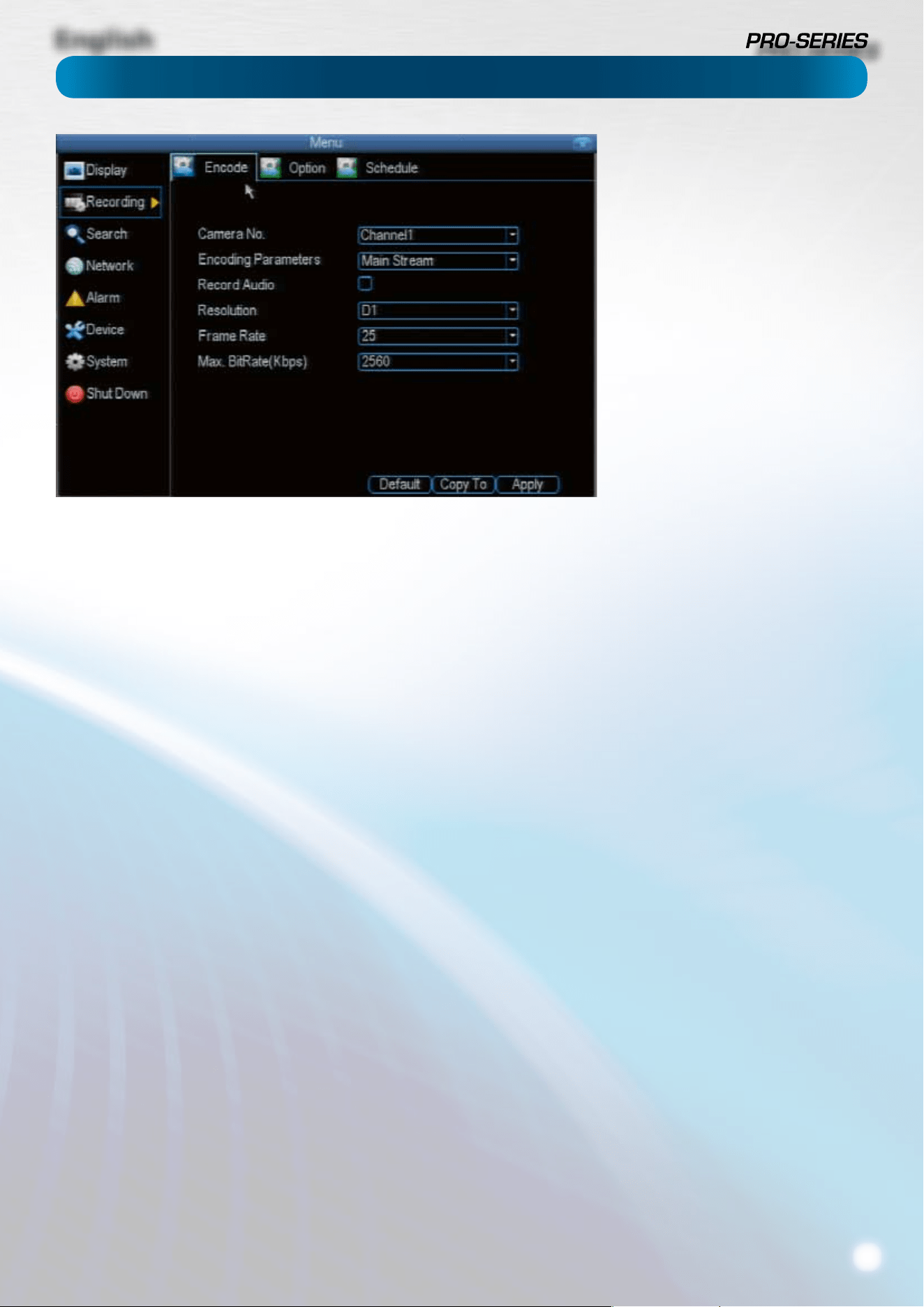
13
Camera No.: The camera feed you want to alter the settings
for. These will be numbered sequentially, and correspond to
the BNC video inputs labelled on the rear of the DVR. Note
that the channel name here is independent of the Camera Name
selected on the Display: Camera menu screen.
Encoding Parameters (advanced user option): Whether
you’re editing the parameters for the mainstream or the
substream.
Main-Stream: The main-stream is the video feed that the DVR
will record and display. This is the higher-quality stream.
Sub-Stream: The sub-stream is the video steam that the DVR
will send to remote devices via a network or the Internet. It is the
lower-quality stream as a reduction in video size makes it easier
to send over a network.
Record Audio: Choose whether the channel you’ve selected
will record audio or not. If you don’t have any audio devices
connected, it’s a good idea to disable audio, as it will save
some space on your HDD.
Resolution: How many “little dots” are going to make up your
image. There are two options:
D1: About the same resolution as a DVD (704 x 480 for NTSC,
or 704 x 576 for PAL). This is the default resolution for all
channels, and we suggest leaving this setting well alone.
HD1: Literally, half of D1 (352 x 480 NTSC / 352 x 576 PAL) and
about the quality of a typical YouTube video. This won’t save
HDD space - the bitrate is the important setting for determining
how much space your recordings require on the HDD.
CIF: 1/4 of D1 (352 x 240 NTSC / 352 x 288 PAL), and about
the same resolution as a low-quality webcam. We can’t think
of a good reason to use CIF as your resolution setting, unless
you’ve some really cunning plan we didn’t think of. It won’t
save any HDD space - for that, you’ll need to change the bitrate.
Frame Rate: The number of frames per second (fps) that the
DVR will record. The default (and maximum) is referred to as
“real-time” and is 30fps (NTSC) or 25fps (PAL).
Reducing the number of frames per second will either
save hard drive space or improve the data-rate per frame
(depending how you set the bit-rate - see the next point).
Remember that your FPS count is the same as saying “take
X photograph per second” (where X is your FPS setting).
5fps doesn’t sound like much, but it’s still ve individual
photographs per second. If maintaining image clarity while
reducing HDD consumption is your priority, it makes sense to
lower the frame rate.
As with all settings on this screen, some experimentation is
encouraged to nd the settings which will work best for you!
Max. BitRate(Kbps): The actual amount of data that the DVR
will use to record video.
The main-stream uses a variable bitrate to record video - the
more movement occurs in the video, the higher the bitrate
will have to be. When there’s little movement in view, the DVR
will automatically reduce the bitrate to conserve HDD space.
If the amount of movement in a recording would require a
higher bitrate to accurately record than you’ve selected as the
maximum, the DVR will attempt to preserve as much of the
quality as possible by applying compression to the image. This
compression will take the form of irregular, fuzzy blocks over
segments or all of the image. If you encounter this, it indicates
that you might need to increase the overall bitrate.
If you’ve set a high bitrate but a low frame rate, the DVR will
still use all the data it can, resulting in potentially higher
quality per frame than at higher frame rates.
The sub-stream uses a constant bit-rate. This makes the
video easier to stream over a network or the Internet.
Recording: Encode
The Recording: Encode menu allows to
alter and customize how the DVR records
footage and “encodes” the les.
“Encoding” is a term which refers to
the compression algorithm (a fancy,
computer term for “make the le smaller
while retaining visual quality”) used by
the DVR.
You can choose and alter:
• the resolution (per channel),
• the frame rate (how many images
per second the DVR records) and
• the data-rate of each video stream.
The higher the data rate, the “better”
your images will look, but the more
space they’ll require on your HDD.
English
14
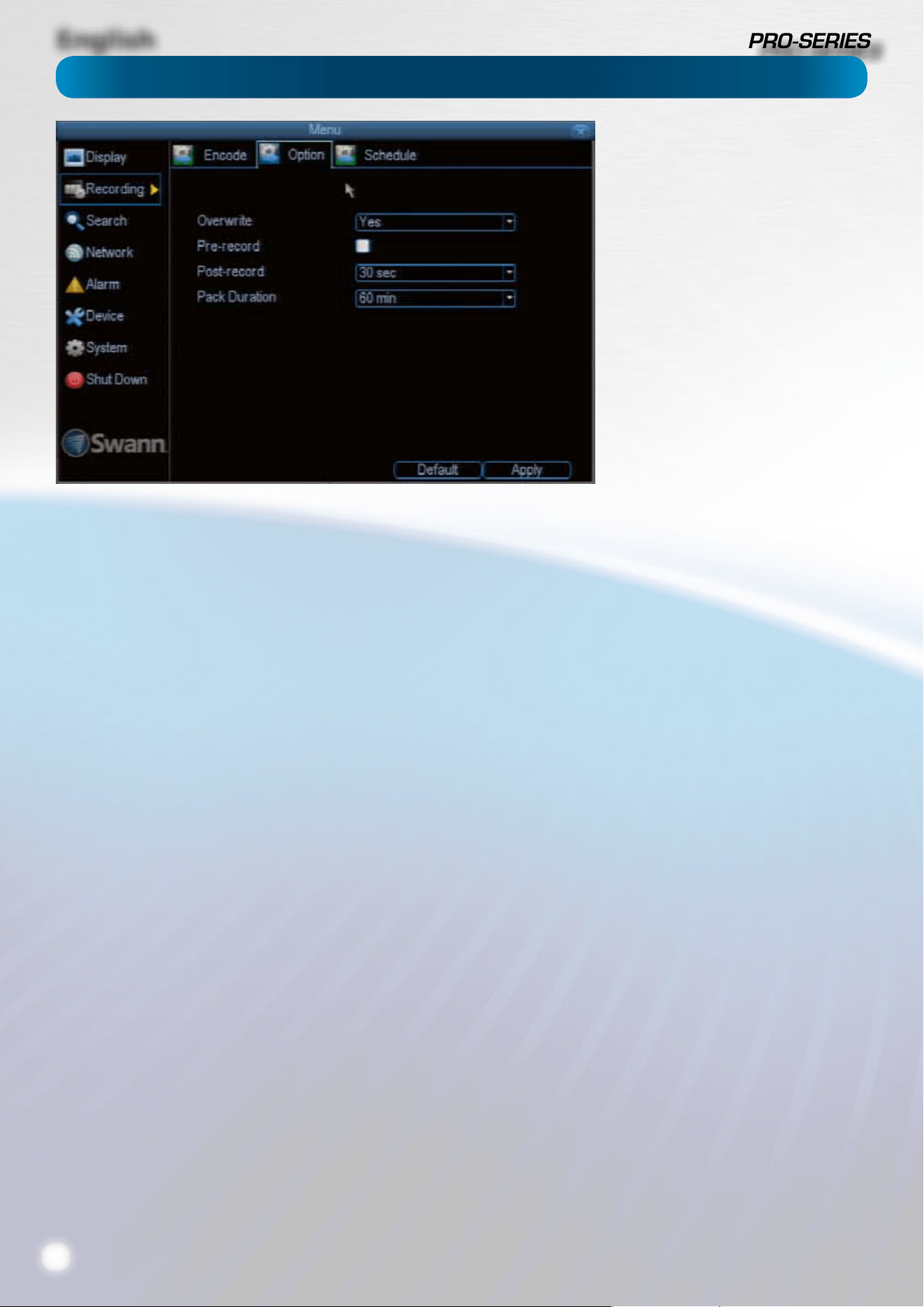
Overwrite: When enabled, the DVR will record over the les
already stored on the hard drive. The DVR will always record
over the oldest les on your hard drive rst.
Using the overwrite option is advisable, as the DVR will always
be able to record events as they happen. However, it does
mean that you’ll need to get important events o the HDD
before they’re overwritten.
Pre-Record: While Pre-Record is enabled, the DVR will record
a few seconds before an event occurs. It’s a little like making
the DVR psychic (but not really - it’s actually just caching a few
seconds of video which it adds to event recordings as they
occur).
If you’re using Motion Detection (recommended) as your
primary recording method, then it’s a really good idea to use
Pre-Record - sometimes, if a motion event is fast enough, it
might have left view before the DVR can trigger a recording.
With Pre-Record, there’s almost no chance you’ll miss it.
Post-Record: How long after an event occurs that the DVR
will continue to record. It can be very useful - for example, if
an intruder or potential target triggers the motion detection
but pauses in view, then post record being enabled will get
a much better look at them. We think that 30 seconds is a
reasonable length for the post-record setting, but can be
higher (the options are 1, 2, 5 or 10 minutes) depending on
your unique circumstances.
Pack Duration: Pack Duration is a measurement of how long
the DVR will record for before splitting the output le into
discrete units. “Packs” are something like the scene numbers
on a DVD - though the video is broken up into separate units,
it will still play through as one continuous movie (unless
interrupted by the schedule or motion detection turning the
recording on or o). If you don’t want to worry about setting
Pack Durations, you can leave it on the default value; it will
make little dierence to the day-to-day running of the DVR.
Recording: Option
The Recording: Encode menu allows to
alter and customize how the DVR records
footage and “encodes” the les.
“Encoding” is a term which refers to
the compression algorithm (a fancy,
computer term for “make the le smaller
while retaining visual quality”) used by
the DVR.
You can choose and alter:
• the resolution (per channel),
• the frame rate (how many images
per second the DVR records) and
• the data-rate of each video steam.
The higher the data rate, the “better”
your images will look, but the more
space they’ll require on your HDD.
English
15
Important Guidelines
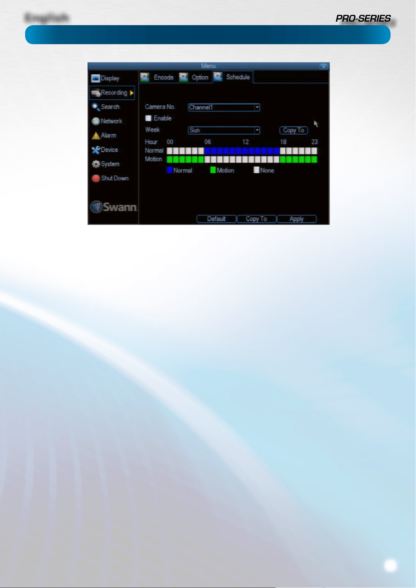
The schedule presented on-screen applies to one channel on
one specic day of the week only.
Use the Copy To functions to quickly assign identical schedule
layouts to multiple days/channels at once.
Be careful when programming your schedule. It’s one of the
most important aspects of setting up your DVR, and if it’s
wrong in any way, it could lead to disastrous complications
later.
Copy To: There are two Copy To buttons on the Schedule
Menu screen.
Copy To (Week/Day): This is located above the schedule itself,
next to the Week drop down menu where you can select a day
of the week to edit the schedule for.
This button will allow you to copy your settings from one day
to other days. It won’t aect any other channels.
Copy To (Channel): Located at the base of the screen, with
Default on one side and Apply on the other. This will allow
you to copy the schedule from the channel you’re editing to
another channel or channels.
Recording Modes:
There are two types of recording to choose from.
Normal: The DVR will constantly record for any period where
Normal is selected. You won’t miss anything, but constant
recording will ll your hard drive very quickly. (The DVR does
record the equivalent of a DVD lm every two hours on every
channel, so that’s rather a lot of data!) Typically, we suggest
Motion as a better recording mode for most users.
Motion: The recommended recording setting for most
applications. The DVR will only record when it detects
something moving in front of a camera, and will then only
record footage from the camera(s) that do detect motion.
Before setting any of your schedule to Motion, ensure that
Motion Detection is properly congured for the channel(s)
you want to associate with it. See “Alarm: Motion” on page
24 for more information about setting up and conguring
Motion Detection.
None: As the name suggests, the DVR will not record anything.
This isn’t really a mode, but it’s listed here for completeness.
Recording: Schedule
English
16
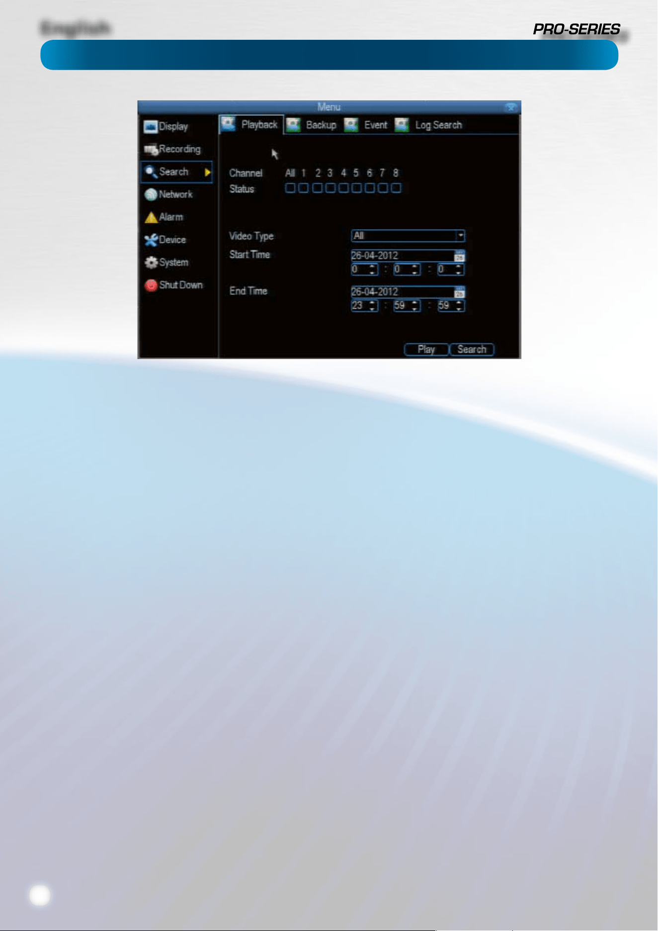
To initiate playback:
• Select the channels you’d like to playback. Note that
the DVR can only playback a limited number of channels
simultaneously: the DVR cam playback 2 channels at
realtime, and up to four channels at near-realtime.
• From the Video Type menu, select the type(s) of video
you’d like to playback. The options are Manual, Schedule
and Motion.
• Set your Start Time and your End Time.
• Select Search.
• Choose which event(s) you want to play back, and up to
four cameras you’d like to view the video(s) from.
• To initiate playback, select Play.
• C
Why can’t I playback all channels at once?
The DVR only has so much processing power, and we’ve
congured it so that it has more resources dedicated to
recording than to playback.
While you’re playing back footage, the DVR continues
to monitor and record normally. Recording from four or
eight channels at once (depending on your model) is so
resource intensive that playback is limited to two channels
simultaneously in realtime.
If you do require playback of more channels than the DVR is
capable of at once, then we suggest using the Backup process
to copy information o the DVR and then playing it back via
the remote interface on a PC.
When we say that it can “playback so many channels at near
real-time”, this doesn’t mean things will be in slow motion.
Rather, the action will unfold at normal speed, but be
represented by half the number of frames per second (12.5fps/
PAL or 15fps/NTSC).
Notes about playback, backup, media and so forth can go
here.
Search: Playback
English
17
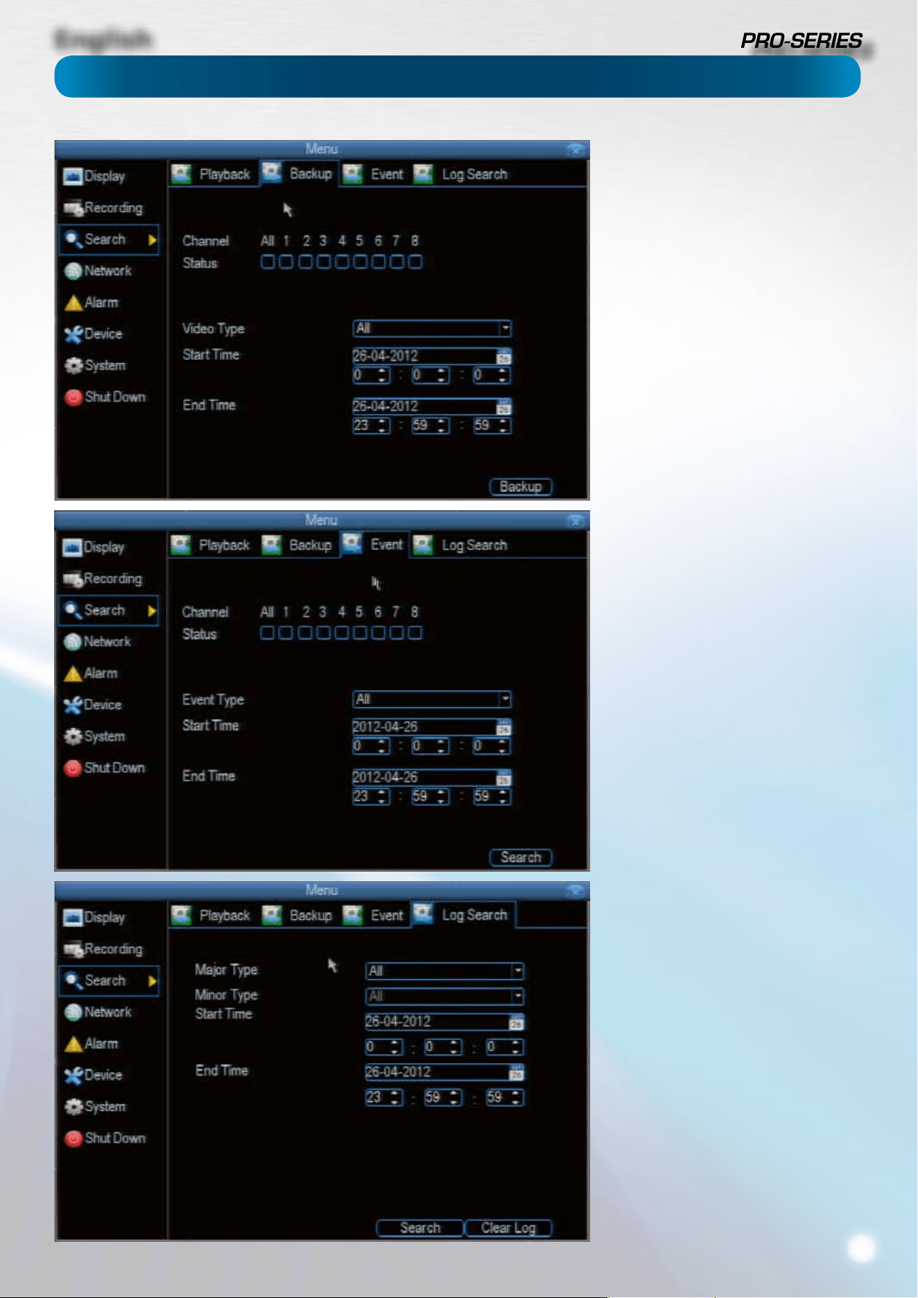
To backup footage:
• Connect a USB ash drive or a USB
HDD to the USB port on the front of
the DVR
- OR -
• Connect an eSATA HDD to the eSATA
port on the rear of the DVR.
• Choose the camera(s) you want to
backup footage from.
• From the Video Type menu, select
the type(s) of video you want to
backup. The options are Manual,
Motion and Schedule.
• Set your Start Time and End Time.
• Select Backup.
The Event Search menu will show you
recordings that were triggered by the
DVR detecting motion.
Typically, the majority of recordings
based upon “Events” are likely to be
recordings triggered by the DVR’s
motion detection feature.
The search function operates in the same
way as the main playback search: the
only dierence is you’ll select an Event
Type rather than a Video Type.
The Log Search screen operates in the
same way as the other search screens,
but is able to access the entire DVR’s
event log, not just recorded footage.
If you’re looking for an event which has
no recorded footage associated with it
(such as a lost video signal, hard drive
error, Internet communication problem
or similar) this is where you’ll nd it.
Search: Backup, Event & Log Search
English
18
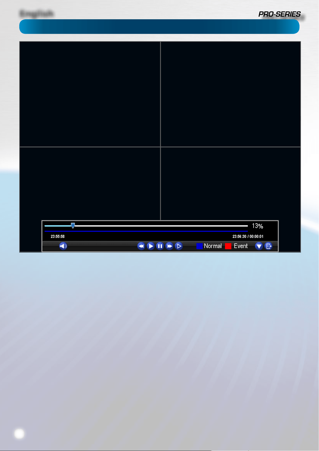
The Playback Interface
The Playback interface is quite similar to a computer’s media
player, or to the on-screen display of a DVD/Blu-Ray player.
Most of the controls are quite straight forward, and operate in
the same way as a standard media player’s.
Current Position: A basic progress meter. You can click to
move to the current position icon to quickly scan through
video events.
Volume Control: Alters the output volume of playback.
Rewind: Reverses footage.
Play: Plays footage forwards at normal speed.
Pause: Stops playback but retains still images onscreen.
Fast-Forward: Speeds up playback.
Step: Moves a single frame forward in the video. This will
usually be 1/30th (NTSC) or 1/25th (PAL) of a second.
Slow: Plays back footage at reduced speed. Press multiple
times to further reduce the speed: 1/2 speed, 1/4 speed, 1/8th
speed, 1/16th speed and so on.
Recording Type: Whether the video being played back was
recorded under normal recording (blue) or based on motion
or an alarm event (red).
Hide Console: Maximizes the area onscreen for playing back
your footage by hiding the on-screen controls.
Exit Playback: Leaves the playback interface and returns to
the live viewing mode.
Remember: Playback Limitations
While you’re playing back footage, the DVR continues to
monitor and record normally.
Recording from four or eight channels at once (depending on
your model) is so resource intensive that playback is limited to
one channel in realtime.
You can playback more channels at once (up to 4) but the
frame rate will drop proportionally to the number of channels
being played back.
English
19
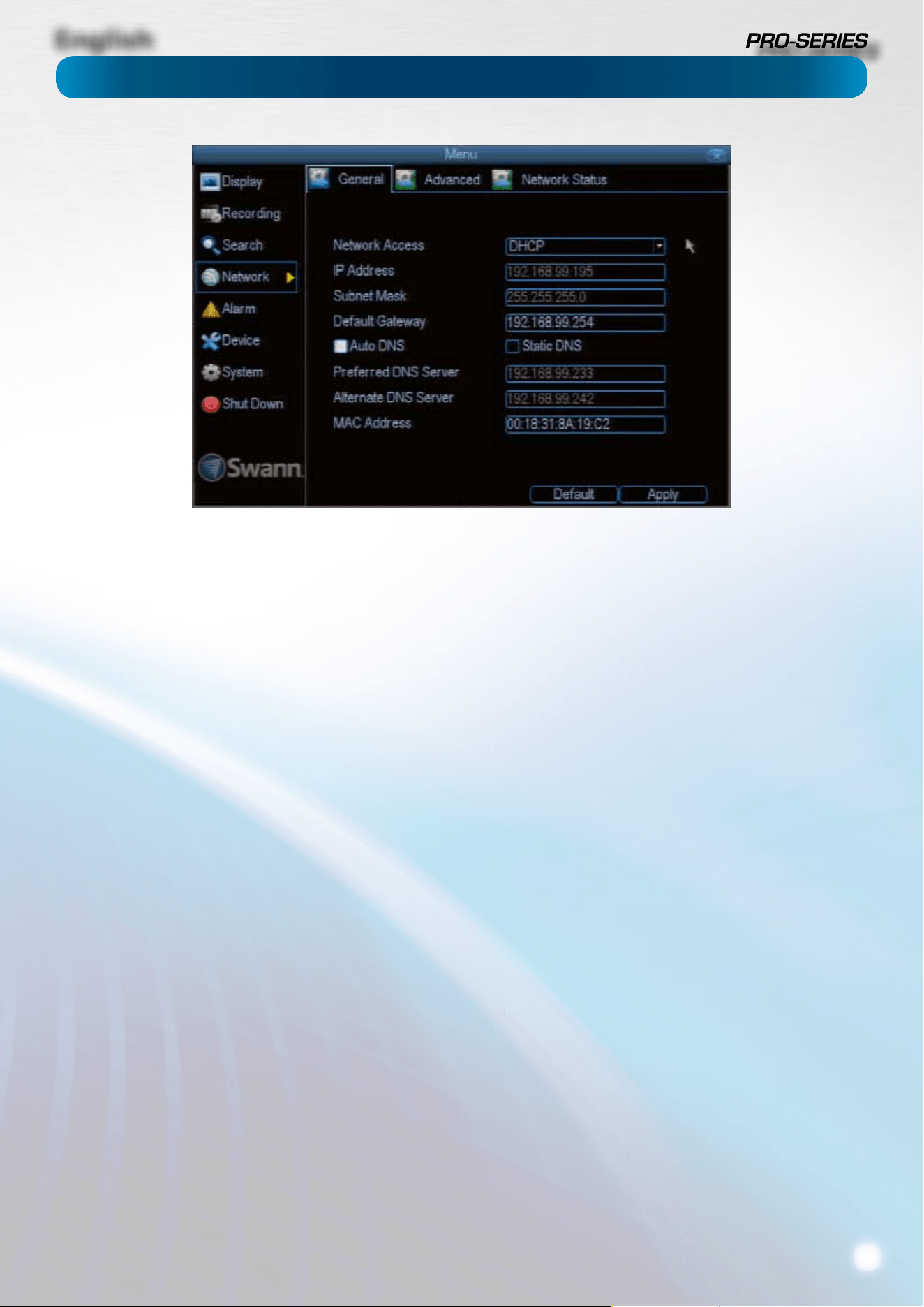
Network Access: Here you can choose between the three
dierent types of networks that the DVR can be connected to.
The three types of networks are:
DHCP: DHCP (Dynamic Host Conguration Protocol) is a
system where one device on your network (usually a router)
will automatically assign IP addresses to devices connected to
the network.
STATIC: Static networks require all devices need to have their
IP addresses manually dened, as there is no device dedicated
to automatically assigning addresses.
PPPoE: An advanced protocol that allows the DVR to be more
directly connected via a DSL modem. This is an option for
advanced users only.
IP Address: Just as houses and businesses need to have an
address which identies their location on the road network,
so too do computers and other devices need addresses (called
IP ADDRESSES) to identify their position on the electronic
network. The DVR uses IPv4 addressing, which consists of four
groups of numbers between 0 and 255, separated by periods.
For example, a typical IP address might be “192.168.1.24” or
something similar. The most important thing when setting the
IP address is that nothing else on your network shares that IP
address.
Subnet Mask: If the IP address is like a street address, then a
subnetwork is like your neighborhood. This will be formatted
in a similar way to the IP address (ie. four numbers up to 255
separated by periods) but contain very dierent numbers. In
the above example, the Subnet Mask might be something like:
“255.255.255.0”.
Default Gateway: This is the address of the “way to the
Internet” - to continue the road analogy, this is like your local
access point to the highway. This is an IP address in the same
format as the others, and is typically very similar to the IP
address of the DVR. To continue the above examples, it might
be something such as: “192.168.1.254”.
Auto DNS / Static DNS: Choose how you’d like to dene your
DNS servers. We recommend leaving it on Auto unless you’ve
got a specic reason not to.
Auto DNS: The DVR will automatically choose a DNS server.
This is the recommended setting.
Static DNS: If you need to manually dene a DNS server, then
choose Static DNS. This is recommended for advanced users
only.
Preferred DNS Server: “Domain Name System”. Everything
on the Internet is located via an IP address - however,
for ease of use, we associate domain names (such as
“www.exampledomainname.com”) with those IP addresses.
This index is accessible in many locations online, and we call
those locations “DNS servers”.
DNS for STATIC conguration: Under most circumstances,
you can set the DNS Server address to be the same address as
your router (this is usually the same address as Gateway).
DNS for DHCP conguration: Typically, the DNS Server
address will automatically be detected by the DVR. In some
cases, you’ll need to enter a value - the address of your router
(the same as the Gateway) should work.
Alternate DNS Server: A backup DNS server. This is here as a
redundancy - your DVR will probably work without one.
MAC Address: The Media Access Control address. This is a
unique code which nothing else should share. You can’t
change this one - it’s hard set when the DVR ships out.
Network: General
English
20
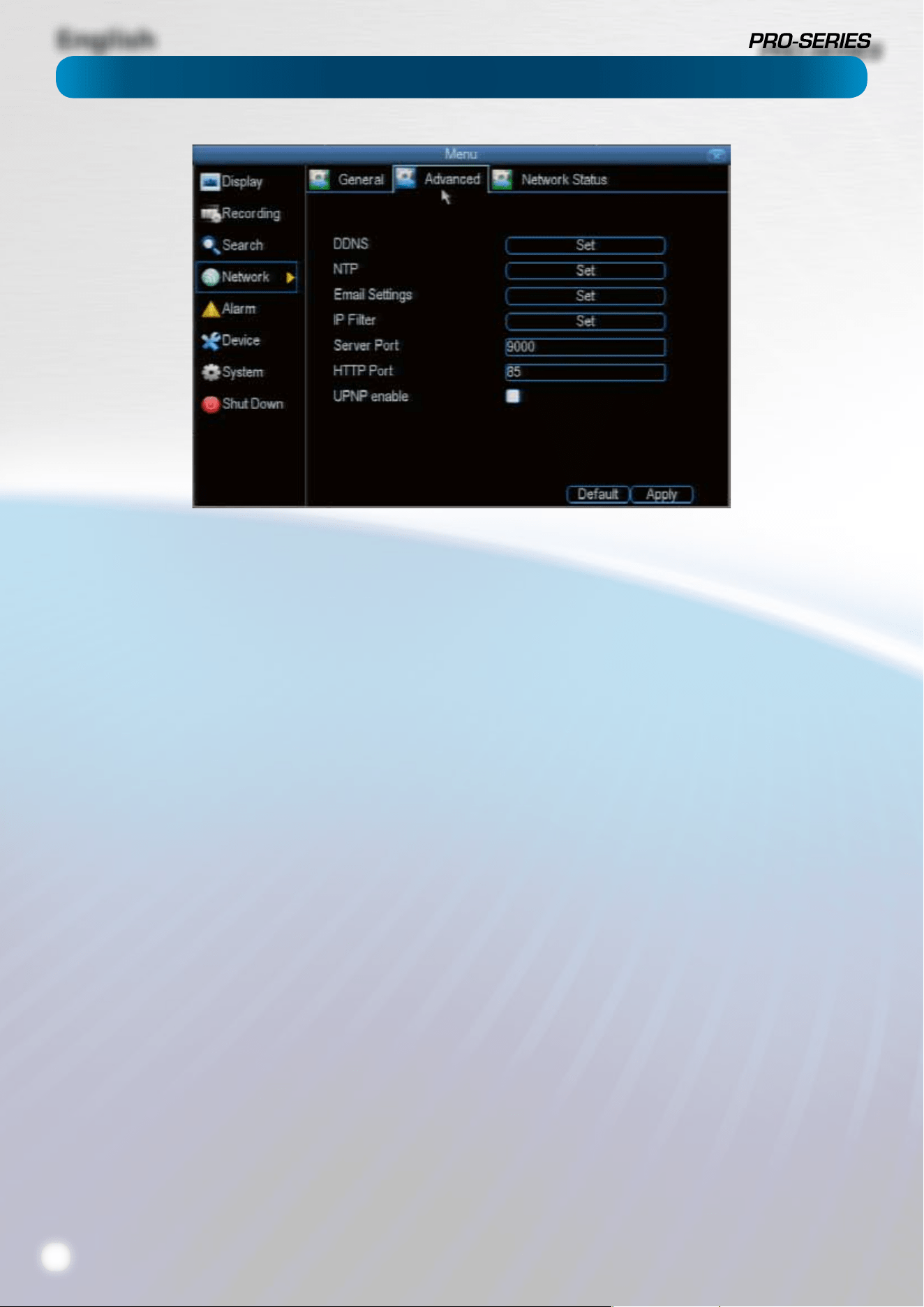
DDNS: The place to congure the DVR to automatically
update a dynamic DNS service. If you want to remotely access
the DVR via the Internet, you’ll probably need to congure a
DDNS account. See “Network: Advanced: DDNS” on page 21
for details on setting up and conguring the DDNS.
NTP: Network Time Protocol. If you’ve got the DVR connected
to the Internet, you can have it automatically sync time with
an online server.
Email Settings: Where you can congure the DVR to work
with an email account of your choice. This must be correctly
congured for the DVR’s auto-email feature to work.
IP Filter: An advanced feature which allows you to exercise
precise control over what devices/IP address(es) are allowed to
communicate with the DVR and which are not. Recommended
for advanced users only.
Server Port: This is the port that the DVR will use to send
information through. The most important things are that:
• You’ll need to enable UPnP on your router so your router
can selectively open these ports, allowing the DVR to
communicate via the Internet. If your router doesn’t
support UPnP, you have two options. You can either get
a new router (which we’d actually recommend - UPnP
is such a good feature!) or you can manually forward
ports from the router to the DVR. Port forwarding is a
technical and involved process, recommended only for
the technically inclined.
• Nothing else share this port. The default port number is
9000, which is not used by many other devices/programs.
However, particularly if you have another DVR or DVR-like
device, something might be using this port already. If this
is the case, change this value to be unique.
• You’ll need to know this port value when logging in
from a mobile device - so, if you change it, remember
what it is!
HTTP Port: This is the port through which you will be able to
log in to the DVR.
• Like the server port, it will need to be forwarded properly
in order to ensure smooth, latency-free communication.
The default value is “85”, as this port is seldom used by
other devices or applications. If there is another device on
your network using this port, you’ll need to change it to
be unique.
• This is the port number you’ll need to remember when
logging in remotely from a remote PC via the HTTP
interace or the MyDVR software.
UPNP enable: UPnP is a technology which makes conguring
your network easier and faster. To use the UPnP setting on
the DVR, you’ll need a router which supports the feature, with
UPnP enabled. Note that many routers which do support
UPnP do not come with the feature enabled by default. You
may need to ask your Internet service provider to turn it on.
When UPnP is enabled on both your DVR and router, the Ports
that the DVR requires to be open for access to and from the
Internet will automatically be opened and closed as necessary
by your router, saving you the trouble of manually forwarding
these ports. If UPnP is not enabled, or your router does not
support the feature, you’ll need to forward the ports the DVR
uses from the router to the DVR - since this is a technically
challenging process, we strongly recommend using UPnP if
possible.
Network: Advanced
English
21
How do I deal with a dynamic IP address?
One option is to contact your ISP and request a static IP
address. They’ll usually charge a small fee for doing this. It’s
worth noting that not all ISPs oer static IP addresses.
If your ISP does not oer static IP addresses then you can use
a dynamic referencing service. We provide one free of charge.
We recommend using SWANNDVR as your DNS service.
This is a free service for Swann DVR owners, which we
directly support.
To create an account with SWANNDVR, go to:
http://mydvr.swanndvr.com/
and click the Registration button.
Follow the prompts to create your account.
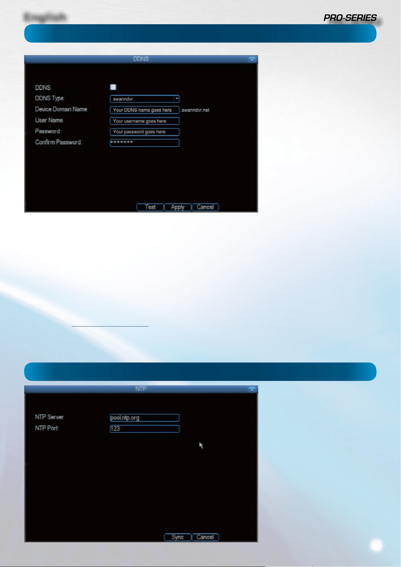
Server: Choose the server that you’re using. The options are
DYNDNS and our own DDNS server, SWANNDVR.
Device Domain Name: Enter the host name that you set up in
your DDNS service. This is the address you use to access your
network. For example: yourhostname.swanndvr.net
Username and Password: Here, enter the username and
password you setup with your DDNS server. These do not
have to match your username/password combination in
either your DVR or router (for the sake of security, we suggest
making them dierent).
For SwannDVR users: Your username is the email address you
used to register the account. The password is whatever you
selected when you registered.
Static and Dynamic IP Addresses
In much the same way as your home
network can use static or dynamic IP
addresses, many Internet providers
don’t issue (or charge more for) a
static IP address for users. The easiest
way to nd out is to contact your
Internet service provider. Alternately,
you can access the www.whatismyip.
com service, make a note of your IP,
then reboot your router/gateway.
This should refresh your Internet
connection. If your IP address stays
the same, you’ve probably got a static
IP address. If it changes, you have a
dynamic IP address.
Particularly important if you’ve enabled
NTP - set this to the time zone where
you happen to be. For example, people
in eastern Australia (Canberra, Sydney
and Melbourne) choose GMT+10:00,
whilst the Eastern Time zone in the
USA and Canada is GMT-05:00. (GMT
stands for Greenwich Mean Time - it’s
the baseline that keeps all the dierent
time zones in sync.)
NOTE: Some NTP servers are NOT fully
compatible with DST. This may cause
your system to double-count adding
one or removing one more hour than
they should, or cancel each other out.
You may need to intentionally change
your time zone to compensate, or simply
not use NTP and DST simultaneously.
Network: Advanced: DDNS
Network: Advanced: NTP
English
22
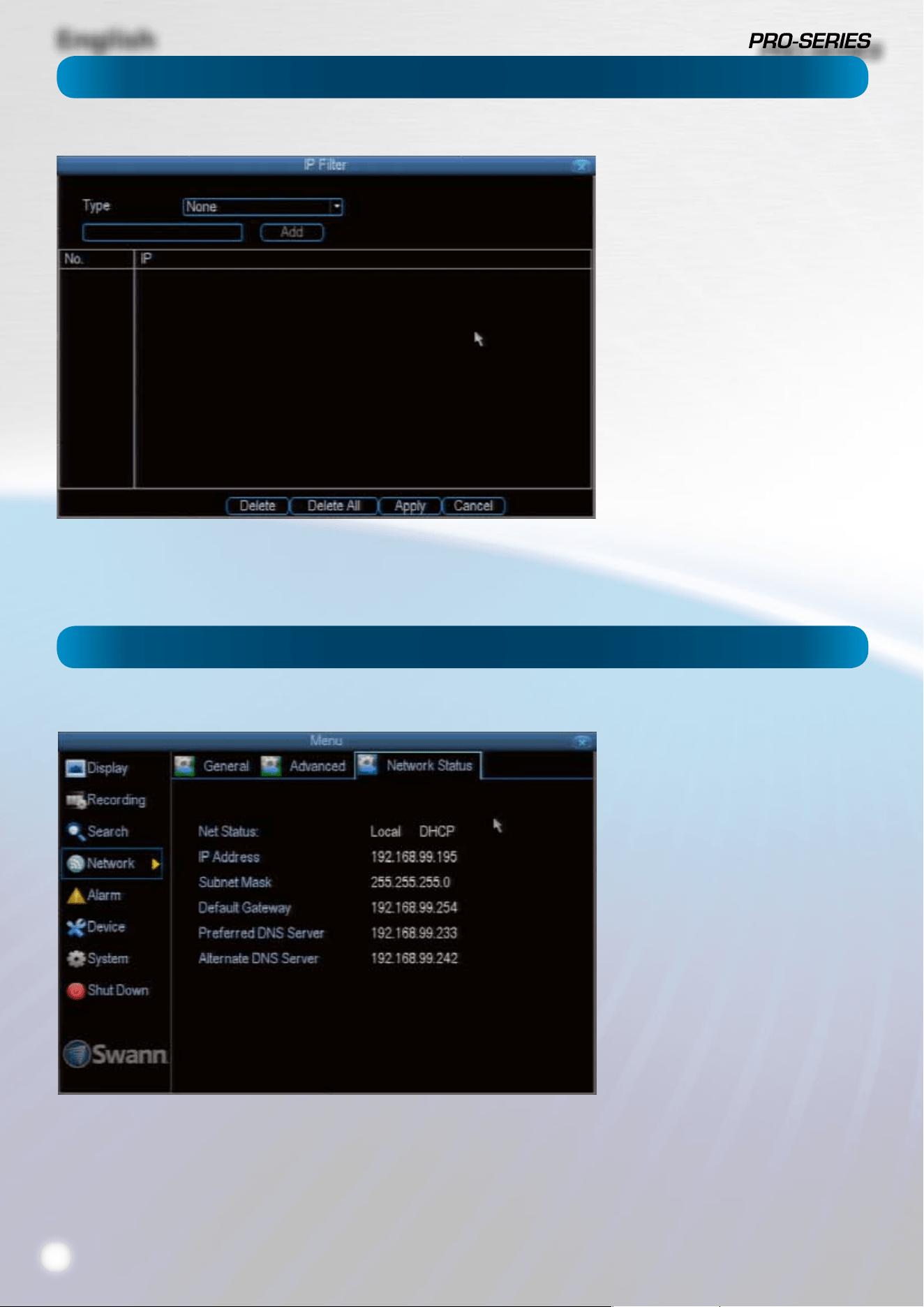
The IP Filter can be used to modify
which IP addresses have permission to
talk to the DVR and which do not.
This is an advanced feature, and is
recommended for advanced users only.
Tinkering with things here - if you’re not
sure what you’re doing - is more likely
to break things than making anything
better.
Network: Advanced: IP Filter
Network: Network Status
The Network Status screen shows
you a quick summary of your
network settings. You can’t alter
things here - see the General
and Advanced tabs for places to
actually alter things.
English
23
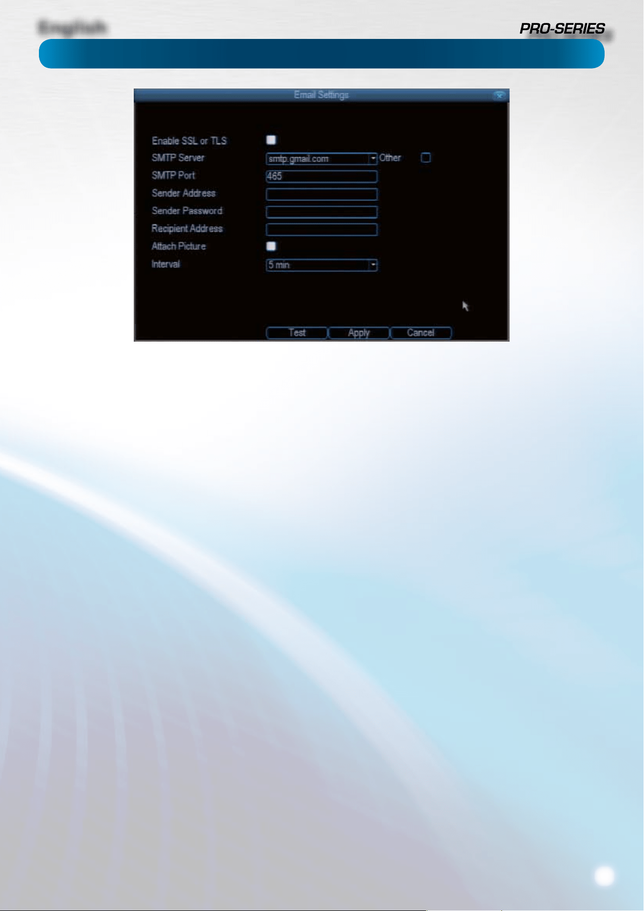
Network: Advanced: Email Settings
If you want the DVR to occasionally drop you a line, share
news, tell you about its day and - more importantly - tell you
what’s going on around your home or business as it happens,
then you can congure it to automatically send email alerts as
events happen.
We suggest using Gmail as your email client - it’s quite easy
to set up an account and use it solely for the DVR. We’ve
tested the email procedure with Gmail, and it does work.
Other email servers may not work correctly - many
interpret the procedurally generated email from the DVR
as spam and block the mail from being sent.
For the Auto-Mail function to work correctly, the DVR will need
to be correctly congured with the details of the email servers
and addresses you want to use.
Enable SSL or TSL: Whether the email server you’re using
requires a secure link. This is on be default, and should be left
on if you’re using any of the preset email servers.
SMTP Server: There are three preset options to choose from,
Gmail (smtp.gmail.com), Windows Live Mail (smtp.live.com)
and Yahoo Mail (smtp.mail.yahoo.com).
You’ll need to setup an account with one of these email
providers. All oer free email accounts. To signup, visit the
email provider’s website:
Gmail (Google): www.gmail.com
Yahoo Mail: mail.yahoo.com
Windows Live Mail: www.hotmail.com
You can use any email server you like if you tick the box labeled
“Other”. You’ll have to dene the email server you’d like to use
manually, and you’ll need to know details about the server,
such as the SMTP port they use, as well as whether they use
SSL or TLS security protocols. Contact your email provider if
you need to learn this information.
We recommend using one of the presets, and can oer better
support for users and the DVR will automatically adjust some
settings (such as the SMTP port number) to make conguration
signicantly easier.
SMTP Port: The SMTP port used by the email provider of your
choice. This eld will automatically self-populate if you use
one of the presets.
Sender Address: The address you’re sending the email from.
This will be the username you’ve set up for the email server
you’re using, followed by “@” and then the email server. For
example: “[email protected]om” or similar.
Sender Password: The password for the outgoing email
account.
Recipient Address: The email address you want the DVR to
send emails to. This can be any email address you like, however,
bear in mind that the DVR might send a large number of
automatic emails under certain conditions.
Attach Picture: While this is selected, the DVR will attach a
small image to each email alert (where applicable).
For motion-based email alerts, this will be an image of
whatever triggered the motion detection.
Interval: The length of time that must elapse after the DVR
sends an email alert before it will send another.
Short Interval settings are likely to lead to huge numbers of
alerts being sent by the DVR - perhaps even several emails
for one event (if that one event lasts longer than the interval
setting). On the other hand, a long interval setting might
mean you’ll miss a specic update that you needed. There’s no
right answer, and you’ll probably have to ne-tune this setting
to get the results you’re after - it’ll be dierent for everyone’s
unique circumstances.
English
24
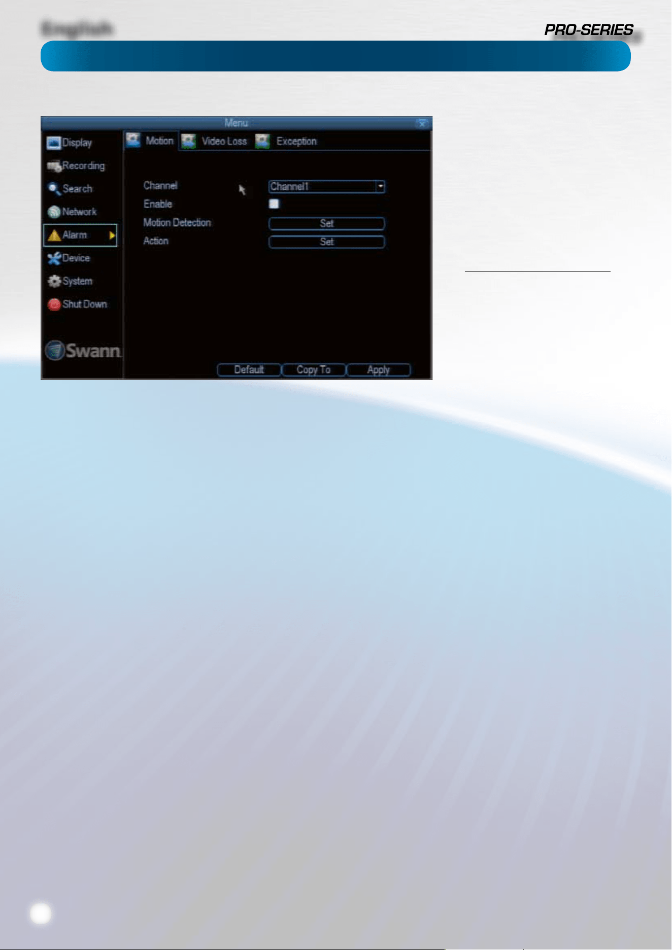
Alarm: Motion
How Motion Detection Works
The way that the DVR looks for motion is quite straight forward
- it’s a process where it compares one frame (that is, a single
image taken approximately a 25th/30th of a second from the
previous image) with the next. A certain amount of “dierence”
between these two “frames” is interpreted as motion.
As a result, the DVR is able to detect when there is a change
in the picture. However, this does not necessarily need to be
something moving in the frame. For example, a light being
turned on or o, a lightning ash or even the sun coming out
momentarily on a cloudy day might be enough to trigger the
motion detection on the DVR. However, as these events last
only a moment (and are relatively rare) they will only create
a few very short redundant clips, which will not take up too
much space or pose a problem with scanning through footage.
This method of motion detection can, however, become
problematic when using wireless cameras. As wireless
technology is susceptible to interference, the static and image
distortion common to wireless systems is often enough to
trigger the motion detection inadvertently.
As a result, we strongly advise against using wireless
cameras with any of our motion sensitive recording
equipment, and advise the use of hard wired cameras. If
you simply must use wireless technology, we advise using
digital wireless technology as this technology is much more
resistant to interference from other wireless equipment and
environmental causes. However, any wireless technology,
digital or otherwise, has serious limitations when combined
with motion detection.
For a similar reason, don’t use PTZ systems and motion
detection simultaneously. The DVR will interpret the
camera moving as ‘motion’ and record. This is particularly true
when using Cruise Mode - as the camera is moving almost
continually, so too is the DVR recording almost continually!
Here, you’ll be able to set the motion detection features of
the DVR for each channel. We suggest that motion detection
is, under most circumstances, the most practical recording
method for the DVR to employ.
How it Works: Once motion detection has been enabled for a
channel, it will register to the DVR as an Motion Event. Thus,
you can use the Motion recording mode in the schedule to
trigger the DVR to record when motion detection triggers an
alarm signal.
Enable: Whether or not motion detection is enabled
on a specic channel. Each channel can be congured
independently of one another.
Motion Detection: Click the applicable Set button to setup
the motion detection area for that channel. See “Alarm: Motion
Detection Conguration” on page 25 for details on how to do
this, and what it means.
Say, for example, you are trying to monitor your front yard,
whilst in the background there is a busy street, and the cars
driving past continually set o the motion detection. What
can you do about it? Setting only part of the camera’s view
to be motion sensitive might be the answer. This is useful in a
number of circumstances, such as monitoring one particular
door at the end of a busy hallway, or a backyard with a tree
that keeps blowing in the wind.
Action: Here you can dene what will happen when the
camera you’ve selected detects motion.
Note: If you’ve used the Copy-To feature to copy from
one camera to another, remember that the Action will be
copied across, too! You will need to reset the action for
each channel.
If you’re planning to use Motion
Detection as the primary (or sole)
recording mode for the DVR, you must
ensure it’s properly congured.
If the motion detection sensitivity is
too sensitive, then the DVR will record
too frequently or continually - any
benet of motion detection will be
lost.
If the motion detection sensitivity is
not sensitive enough, then the DVR
will not record when it should and
may not record anything at all.
We think that motion detection is the
best way to get your DVR to operate
almost autonomously for long periods
of time (typically weeks to months)
without you having to worry about
losing old footage.
However, it is VITAL that it’s
congured correctly!
English
25
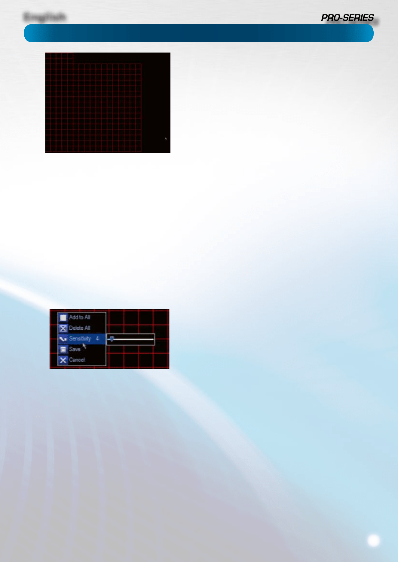
Alarm: Motion Detection Conguration
To set the MOTION DETECTION AREA
In the MOTION DETECTION menu, use the mouse or the arrow
buttons to highlight the SETUP button for the channel you
wish to setup the MOTION DETECTION AREA for, and conrm
by pressing select or left clicking.
• You will see a grid of red boxes. The outlined boxes mark
the area that is sensitive to motion. The area without
the red outlines is not sensitive to motion.
• Use the mouse to move the cursor around the screen.
• By pressing select or left clicking an area in the grid, you
can toggle motion detection ON or OFF in that location.
• Areas marked by red boxes will be sensitive to motion,
those not marked will not be.
• Click and drag to select the area you want to select or
deselect.
Sensitivity: The Sensitivity setting is controlled by a slider,
allowing you to set a value between 0 and 50. The lower the
number, the more sensitive the motion detection will be.
Typically, values between 5 and 10 will give good results in the
daytime.
At night, you may get numerous false triggers unless you
raise the sensitivity setting, perhaps as high as 25 - 30. This is
because when cameras (particularly CMOS-based ones) use
active infrared night vision, they dramatically increase the
gain controls to the image sensor. This creates a lot of “noise”
in the camera’s images, which are interpreted by the DVR as
motion.
There are a few steps you can take to minimize the amount of
noise in your images.
• Try adjusting the Image Settings (see “Camera: Display”
on page 11 for details) to ne-tune the brightness and
contrast to get a more stable image.
• Limit the motion sensitive area to only the areas in view
that a taget could be. In particular, large featureless areas
in the camera’s view are the ones most likely to give false
triggers - turning o the motion sensitivity to any area
a target cannot move infront of will help reduce false
triggers.
Note: The motion detection feature will seem more sensitive
at night, particularly when using low-light or active infrared
cameras. We recommend that you test your motion detection
sensitivity both during the day and at night to ensure your
sensitivity setting is suitable for either lighting condition.
Notes
Wireless cameras are not recommended for use with the motion
detection.
Motion detection is not recommended for use with PTZ systems.
Avoid enabling motion detection on a channel which has a PTZ
system attached to it - especially when the PTZ system is set to
Cruise Mode.
Setting the motion detection at high sensitivity levels (4 or lower)
increases the frequency of false alarms. On the other hand, low
sensitivity levels (20 or higher) increase the risk that a signicant
motion event (such as an intruder) will not trigger the motion
detection to record.
Check the Motion Detection settings both during the day
and at night. In low-light conditions (or when your cameras
are using infrared night vision) the DVR may be more or less
sensitive to motion, depending on your unique circumstances.
The dierence might be very dramatic!
Image Sensors: CMOS and CCD
There are two kinds of CCTV cameras out there: CMOS and
CCD. Neither technology is inherrently “better” but they’re quite
dierent and you may need to adjust your motion detection
sensitivity to suit the kind of cameras you have.
CCD: A Charged-Coupled Device outputs a clear, stable image. It’s
the best kind of sensor to use with motion detection, and typically
requires lower settings (that is: lower number, more sensitive).
CMOS: A Complementary Metal–Oxide–Semiconductor is a
dierent kind of image sensor, producing bold, vibrant images.
It tends to have more noise than CCD, and typically requires a
higher setting (that is, a higher number, which is less sensitive).
Weather
The weather conditions are going to aect your motion detection.
Dramatic weather phenomenon such as heavy rain, strong
winds, lightning and so on may trigger the motion detection with
surprising frequency.
On the other hand, things like fog, mist and other obscuring
kinds of weather might mask or obscure something moving to
the point that the DVR fails to detect them.
English
26
Alarm: Motion Detection - Action
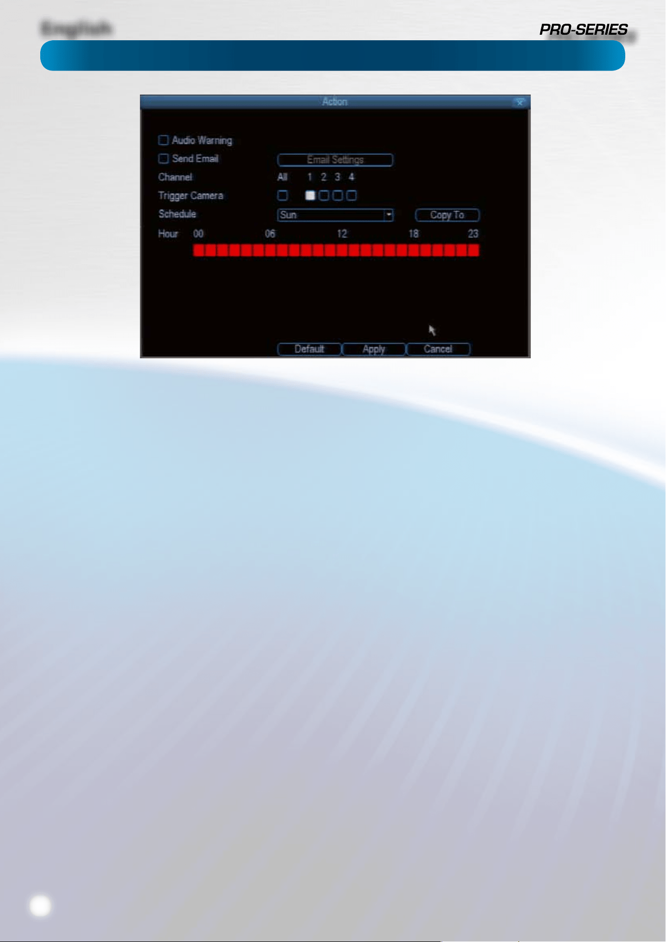
Audio Warning: The DVR will use its internal buzzer to emit an
alarm tone. It sounds like an old computer indicating an error,
or a large truck backing up.
Send Email: The DVR will send an auto-email alert when
the event type you’ve selected occurs. The Email Settings
button will take you to the same email conguration screen
accessible from the Network menu - see “Network: Advanced:
Email Settings” on page 23 for details.
Trigger Camera: You can dene one camera’s motion
detection to trigger recording on one or more other cameras.
This can be useful in a number of situations. For example:
• If you’ve two cameras overlooking a yard, one with a wide
view from well overhead and one with a much narrower
view of a corner or path. You may nd that using the
camera with the narrow view for motion detection gives
fewer false triggers and doesn’t miss an event as often as
the really wide view might, so triggering the wide view to
record as well ensures you know where the subject went
after they left the narrow view.
• One camera might face a public area, while another
camera looks down a private corridor which exits into the
public area. Having the camera in the private area trigger
the one in the public area to record can give you a record
of where a subject went after they left the private area,
without lling your hard drive with recordings triggered
by random passers by.
Schedule: You can change how the DVR Actions events at
dierent times. For example, a motion event occurring during
business hours might be perfectly normal, whereas one
occurring at four in the morning might indicate something
much more severe is happening.
Some tips to customizing your motion detection actions:
• Consider how important it is to be notied of motion
events as they happen.
Using the email alerts is a great way to be kept up-to-speed
on what’s happening, but may quickly become annoying if
something occurs which will generate a number of false triggers.
As a rule, we suggest employing the email alert only on interior
cameras during times that noone should be moving about in
front of them.
• It can be important to have a complete record of a
subject’s movements and actions for legal reasons.
If your cameras capture an illegal event (typically an intruder,
but we’re continually surprised by stories from our users) it is
important to have as much information as possible.
For example, images of someone in your home may not actually
prove that they broke in - but footage of them breaking a window
does. If you use a camera inside the home to trigger all exterior
cameras with a long pre-record time set, then you will have a
record of how they entered in addition to what they did.
• Always consider what’s really important.
Which is the bigger problem - a dozen false triggers per day, or
missing one critical event?
There’s no magic setting which will make motion detection work
perfectly. There will always be some events that it’s not sensitive
enough to catch, or minor happenings that will trigger an overly
sensitive camera to record. Typically, the best motion detection
settings are one’s that give few false triggers but don’t miss
anything.
Even motion detection which fasle triggers a few times per hour
will still save a signicant amount of hard drive space compared
with a constant recording schedule for the same duration.
English
27
Alarm: Video Loss
Alarm: Video Loss
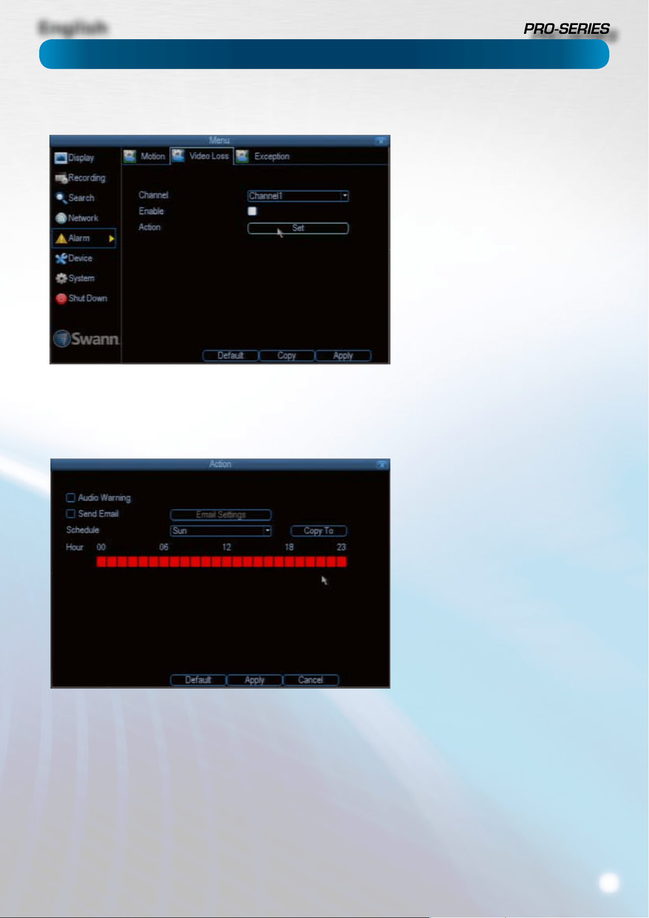
Video Loss is regarded as a potential
alarm event, and is considered to occur
any time that the DVR doesn’t receive an
active video signal on any of its inputs.
The default behaviour of the DVR, when a
channel has no incoming video signal, is
simply to display “Video Loss” in white text
on a black background over the associated
channel. If you’re not using all the inputs
on your DVR, then some channels will be
in “permanent” Video Loss state. Just be
sure that you don’t Enable a video loss
action for these channels.
Channel: Which channel/camera you’d
like to set the Video Loss behaviour for.
Enable: Whether the selected channel
has video loss monitoring active or not.
Action: The action you’d like the DVR to
take when this event occurs. It’s set in
the same way as the Action for any other
event.
Alarm: Video Loss - Action
Audio Warning: The DVR will use its
internal buzzer to emit an alarm tone. It
sounds like an old computer indicating an
error, or a large truck backing up.
Send Email: The DVR will send an auto-
email alert when the event type you’ve
selected occurs. The Email Settings
button will take you to the same email
conguration screen accessible from the
Network menu - see “Network: Advanced:
Email Settings” on page 23 for details.
Schedule: You can change how the
DVR Actions events at dierent times.
For example, a motion event occurring
during business hours might be perfectly
normal, whereas one occurring at four in
the morning might indicate something
much more severe is happening.
You can set the schedule for each “Action”
in the same way as you set the recording
schedule proper. Multiple Action events
can be tied to the same exception, or vice-
versa using clever scheduling.
English
28
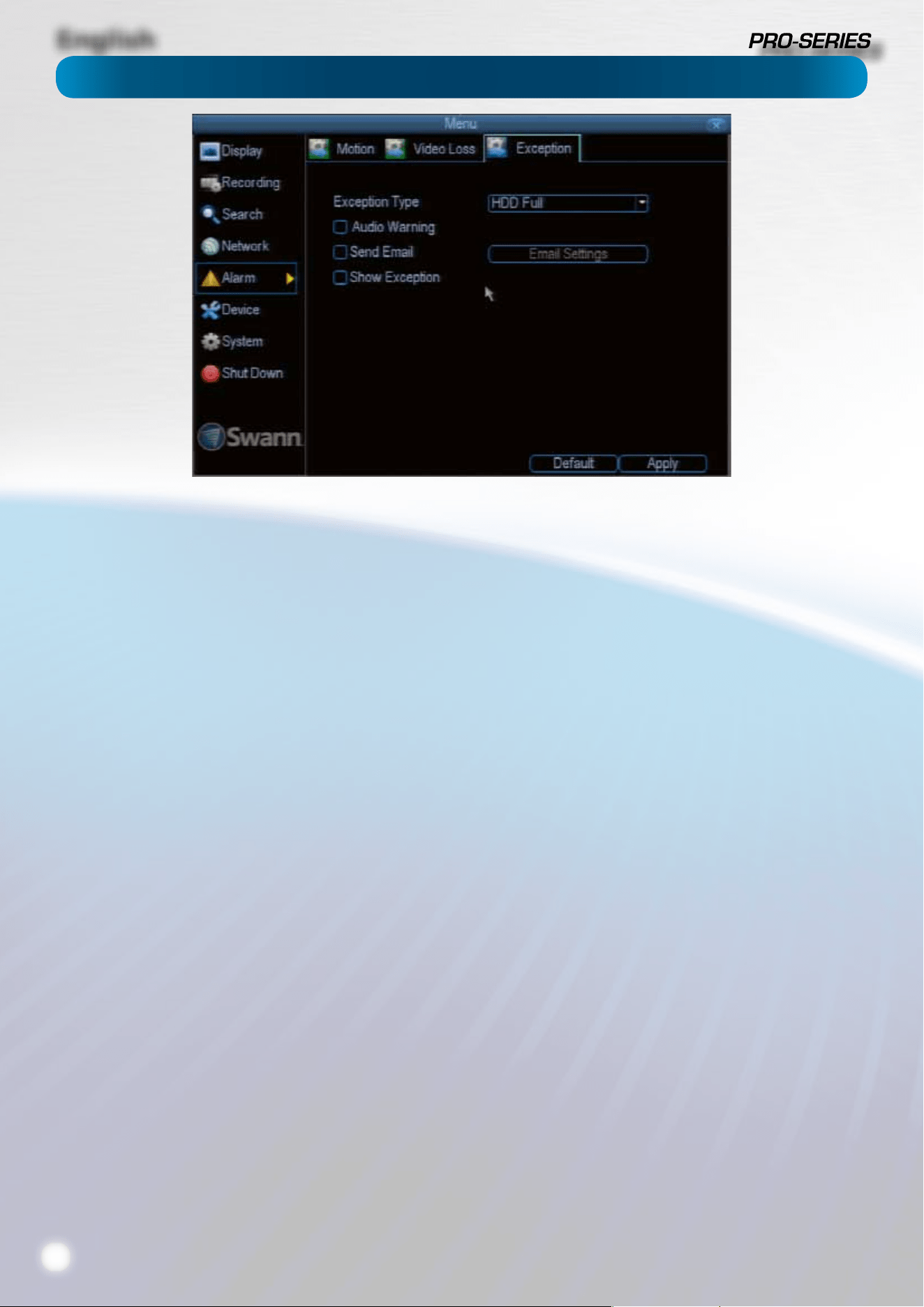
An Exception is any deviation from the DVR’s normal
behaviour - phrased another way, it’s like saying the DVR’s
been working ne except for these events
Exception Type: What event type you’d like the DVR to react
to. By conguring the Action for these events, you can create
any combination of audio alerts (see below) or auto-emails to
be sent for dierent event types.
HDD Full: As the name suggests, this event occurs when the
DVR runs out of space on the hard drive to save new footage.
This event is redundant if you’ve got overwrite enabled, as
the DVR will automatically delete old footage to ensure it can
continue to record.
HDD Error: Occurs when the DVR has trouble accessing one
or more of its hard drives, or when it cannot detect one at all.
Net Disconnected: Will occur if the DVR has problems
connecting to the Internet. This may indicate a problem
with the DVR’s conguration, a fault with your network or a
problem with your Internet Service Provider (ISP).
IP Conict: This event will occur if the DVR detects another
device on the same network with a conicting IP address. It’s a
little like two houses with the same number being on the same
street - one house might get the other’s mail, or get woken up
at all hours of the night being asked if someone named “Big
Bob” lives there.
Basically, it indicates that two devices are trying to use the
same IP address. This shouldn’t occur if you’re using DHCP
addressing, unless one or more devices is set to use a STATIC
IP (the static addressing method overrides the automatic
assignment process).
Audio Warning: The DVR will use its internal buzzer to emit an
alarm tone. It sounds like an old computer indicating an error,
or a large truck backing up.
Send Email: The DVR will send an auto-email alert when the
event type you’ve selected occurs.
Alarm: Exception
English
29
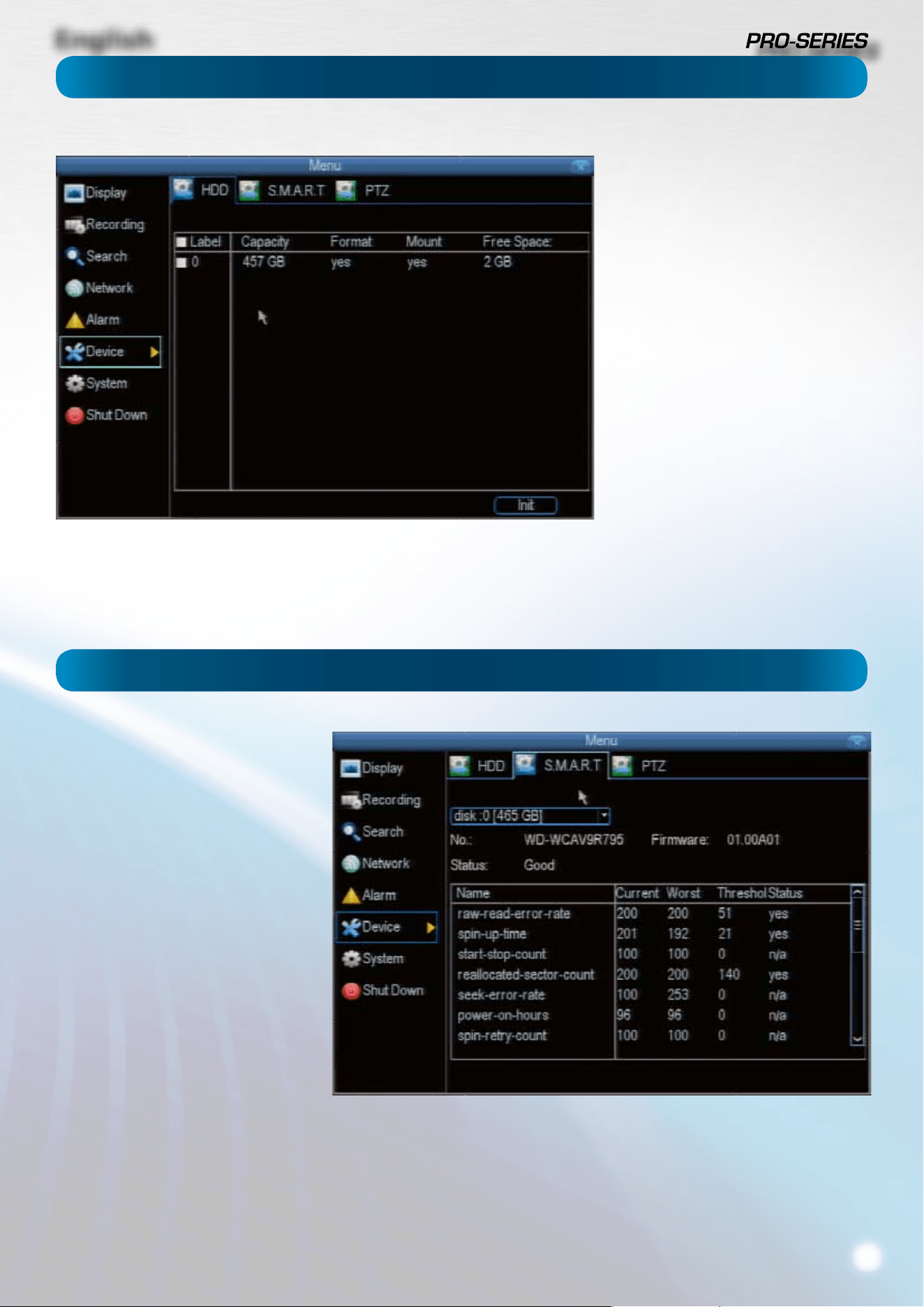
Here you’ll nd a comprehensive list of
hard drives connected to the DVR.
Typically, there will be one entry here,
and it will probably be the hard drive
that came with the DVR. This is not a
problem, and you’ll probably get years
of usage out of the included hard drive.
Note that external drives connected
by either eSATA or USB will NOT be
displayed here.
S.M.A.R.T. (Self-Monitoring, Analysis
and Reporting Technology - gotta love
a good acronym) is your hard drive’s
way of telling the DVR how it’s going.
Status: The current condition of the
hard drive. It should say “Good”. If it
says anything else, this indicates there’s
a problem with your hard drive.
If there’s no problem, there’s little else
to do here, unless reading the output
of the dozens of self-tests the hard
drive performs on itself is of interest to
you.
If you have been confronted with a HDD
Error, or the Status entry doesn’t read
“Good” then you can use the S.M.A.R.T.
information to attempt to diagnose the
problem. The information presented
in the S.M.A.R.T. report is practically
identical to what you’d see on a
desktop PC while using Administrator
Tools, or a similar service.
Device: HDD
Device: S.M.A.R.T.
English
30
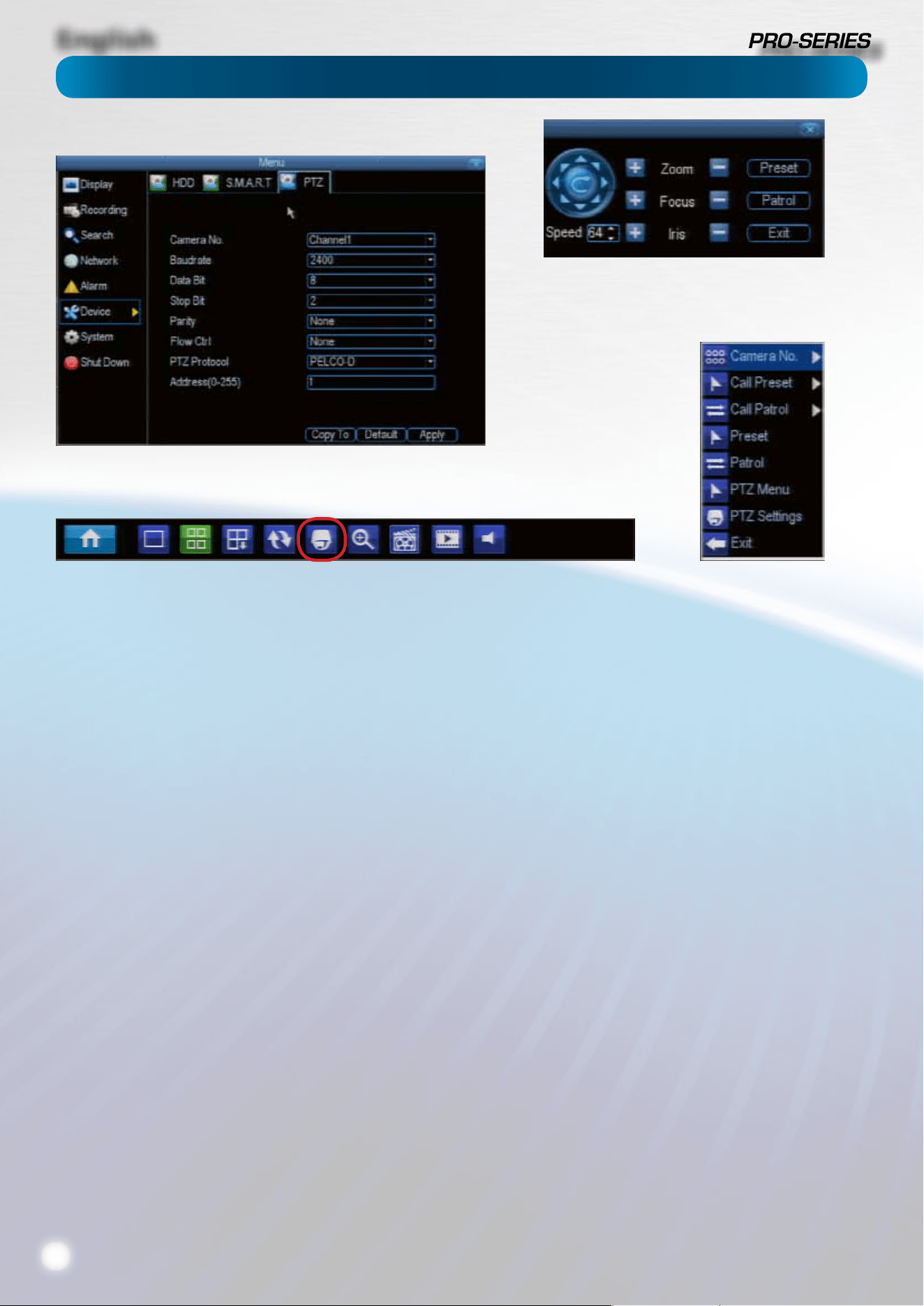
Left: The PTZ Settings menu.
Above: The PTZ controls,
accessed by the PTZ icon on
the menu bar.
Right: The PTZ context menu.
Accessed by right-clicking
while the PTZ controls are
open.
Below: The Menu Bar, with the
PTZ icon highlighted in red.
PTZ Settings
This is where you can congure the DVR to be able to operate
PTZ devices. PTZ stands for Pan, Tilt & Zoom.
The DVR is compatible with many - but not all - PTZ devices
available. For the best results, we suggest using a Swann PTZ
camera, as we know what they’re compatible with and we’ll
be able to oer support for both devices at once (should you
need it).
Camera No: The camera you’d like to associate a PTZ device
with.
Baudrate: Check the PTZ device’s documentation to learn
this value. Most Swann PTZ units operate at 2400 or 9600bps.
Data Bit, Stop Bit & Parity: Options that subtly change the
way the DVR talks to the device. These are important to get
right - check your PTZ device’s documentation to learn the
correct settings.
PTZ Protocol: A protocol is like a language that the DVR uses
to talk to the PTZ device. Ensure that this setting matches the
requirement of your device.
Address (0 - 255): The command address of the PTZ device
you want to associate with this channel.
PTZ Controls
Arrows: Moves the camera in the direction selected.
Speed: How fast the camera will move. The higher the
number, the faster the movement. Note that the actual
speed of movement will depend upon the capabilities of your
particular PTZ device.
Zoom: Increases or decreases the magnication of a vari-focal
lens. Not all PTZ devices have vari-focal lenses.
Focus: Alters the focal point of a PTZ device with a vari-focal
lens. Try adjusting this control if your images seem “soft” or
blurry. Not all cameras support this function.
Iris: Alters how much light gets into the camera by opening
and closing the iris of the camera. Not all PTZ cameras have
an adjustable iris. Also called an “aperture”. Not all cameras
support this function.
Preset: A Preset is a position that the camera is in which is
saved to memory to be retrieved later.
Patrol: Initates patrol mode (also sometimes called “cruise”
mode). You’ll need to dene a series of Preset points for the
camera to patrol between.
Exit: Closes the PTZ controls.
PTZ Context Menu
Camera No: Switch quickly between cameras.
Call Preset: Returns the camera to a Preset point.
Call Patrol: Initiates a patrol of your choice.
Preset: Denes a Preset point.
Patrol: Initiates or stops a patrol.
PTZ Menu: Toggles the appearance of the PTZ Control Menu
onscreen. While the PTZ Control Menu is hidden, the DVR will
still be in PTZ mode, and the context menu can still be opened
via right-clicking the interface.
PTZ Settings: Opens the PTZ Settings menu, where you can
adjust the control method for the camera.
Device: PTZ
English
31
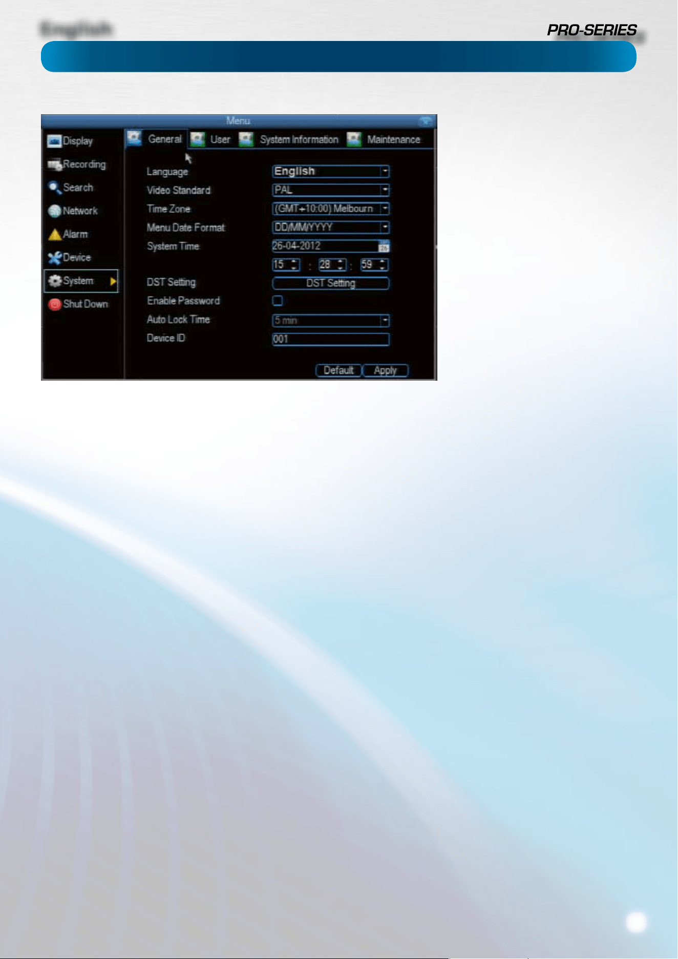
Language: The language that the DVR’s menus, alerts and
other communications will use. This usually defaults to English.
Be careful not to change this setting unintentionally - it might
be tricky to nd the setting to change it back when the DVR is
speaking another language!
Video Standard: Here you can choose between PAL and NTSC.
PAL is used in Western Europe and Australia, NTSC is used in
the US, Canada and Japan. If the DVR’s picture is black and
white, ickering or similar, then this is probably caused by the
video system being set incorrectly. Don’t change this setting
unless advised to do so by Swann Technical Support. You
may not be able to see the DVR’s output on your screen
anymore!
Time Zone: Particularly important if you’ve enabled NTP - set
this to the time zone where you happen to be. For example,
people in eastern Australia (Canberra, Sydney and Melbourne)
choose GMT+10:00, whilst the Eastern Time zone in the USA
and Canada is GMT-05:00. (GMT stands for Greenwich Mean
Time - it’s the baseline that keeps all the dierent time zones
in sync.)
Menu Date Format: The format of the date (eg. DD/MM/YYYY
or MM/DD/YYYY and so on).
System Time: This can be edited manually, or set to update
automatically by using NTP (see “Network: Advanced: NTP” on
page 21).
DST Setting: As the standards for daylight savings dier from
country to country, and often state to state, you might need
to manually tell the DVR exactly when it commences and
ends in your locality. First, turn DST on. We suggest setting the
Daylight Saving Time Mode to Date, and manually entering
the dates and times that daylight savings time applies to and
from, in your locality.
Note: Some NTP servers are NOT fully compatible with DST.
This may cause your system to double-count adding one
or removing one more hour than they should, or cancel
each other out. You may need to intentionally change your
time zone to compensate, or simply not use NTP and DST
simultaneously.
Enable Password: While enabled, the DVR will require a
password to access, even for local users. It’s advisable to
enable password protection
Auto Lock Time: While the password protection is enabled,
the DVR will automatically time-out, whereafter it will ask for
a password before returning to normal functioning. The Auto
Lock Time determines how long a period of inactivity will
cause the DVR to lock itself again.
Device ID: Dierentiates your DVR from other devices. If you
don’t have any other DVR’s or similar devices, then you can
leave this as-is. If you’ve got multiple DVRs running on the
same network, then it’s a great idea to give each a unique ID.
System: General
The System: General menu contains
many of the settings you’ll need to
congure to get the most out of your
DVR system. Most importantly:
• The time and date can be set here.
• You can select the language you
want for the menus/GUI.
• The conguration for automatic
adjustment to daylight savings time
is here.
• You can easily enable or disable
password protection - but will have
to create a valid username/password
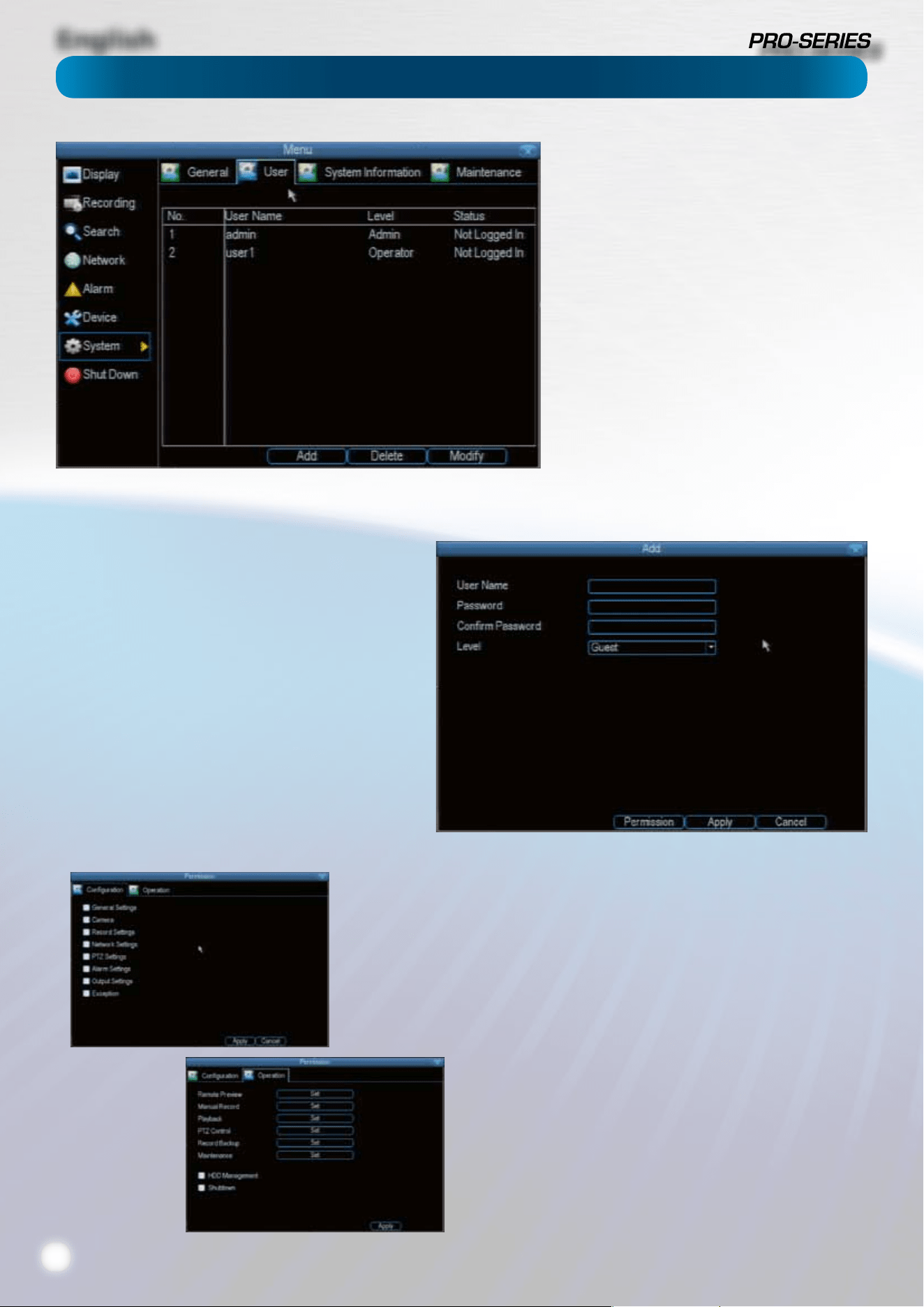
English
32
The System: User menu is where you can dene
and congure the dierent levels of access various
users have to the DVR.
We suggest that at minimum the admin account
be password protected, as it has access to all
aspects of the DVR’s operation.
To add additional users, choose Add.
To remove a user, choose Delete.
To customize a user’s level of access, choose
Modify.
You cannot modify the access level of the
default admin account - they can do everything.
This is to prevent an unfortunate incident where,
for example, no user has the permissions required
to change another user’s permissions - which
could lead to the DVR being, in at least some
senses, inoperable.
User Name: Select a name for the user you want to
dene. The best usernames are short, to the point, are
relevant to the specic user they’re intended for, are
easily memorable and hard to guess.
Password: A password can be any combination of
numbers (0 though 9) between four and eight characters
long.
Conrm Password: Must exactly match the password
for the denintion of a new user to be successful.
Level: There are two default levels of access to the DVR -
Guests and Operators.
Guest: By default, a Guest user has access to the live
images on the DVR and can search through recorded
events. They cannot change any settings or congure
the DVR in any way.
Operator: The default permissions of an Operator allow
them to access and congure all aspects of the DVR.
You can easily customize the level of access each individual
user has. Simply choose the Permission button on either the
Add User or Modify to set the specic access for the user you
want. The Permission menu has two tabs - Conguration and
Operation.
Conguration: The conguration page select which menu(s)
the user can access. There is no heirachy and any combination
of menus can be selected (although some combinations would
make little sense in practice).
Operation: You can select which channels the user has access
to, and what they can do with them. For example, you could set
a user to have permission to view all channels in live viewing
mode, but only playback channels 2 and 4.
Choose the Set button next to each type of access to choose
specic channels that the user can access.
Also, this page contains permissions for HDD Management
and Shutdown. These are surprisingly powerful levels of access:
between them, a user can remove all footage from a DVR’s
hard drive and turn the DVR o. Be careful assigning these
permissions!
System: User
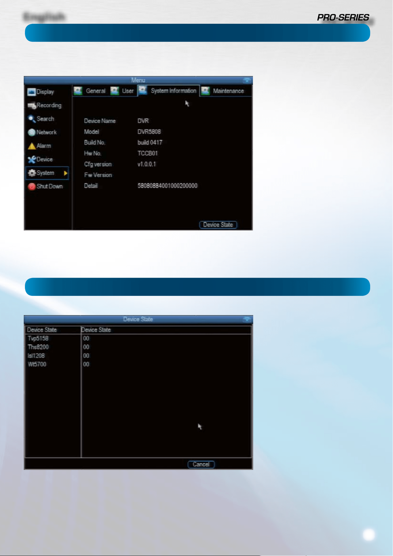
English
33
If you’re looking at the System
Information screen, you’ve probably
been directed to do so by Swann
Technical Support.
If we haven’t told you to come here,
you might be wondering what all the
information means. On a day-to-day
level, the answer is “very little”. However,
if you’re still curious:
Device Name: The name that the DVR
considers to be its own, and what it will
use to register an IP address with your
DHCP host.
The remaining information is for use by
Swann’s Technical Support, in the event
that you require assistance. The various
model and build numbers help us track
down any known issues, or catalogue
new issues as they come to light. It also
helps us gure out if you’re running the
most recent rmware on the DVR, and
whether you’d benet from an upgrade.
System: System Information
System: Device State
The Device State menu contains
information about devices and their
current state. If you don’t know what any
of this means, this indicates two things:
1) You seem to be a balanced, healthy
individual who doesn’t become
obsessed by knowing exactly how the
things they have work, it’s enough that
they do,
and
2) You’ve probably got no reason to be
here. Just back out of this menu and
pretend it isn’t here.
Unless you call up Technical Support
and we ask about something on this
screen, there really isn’t anything to
do here.
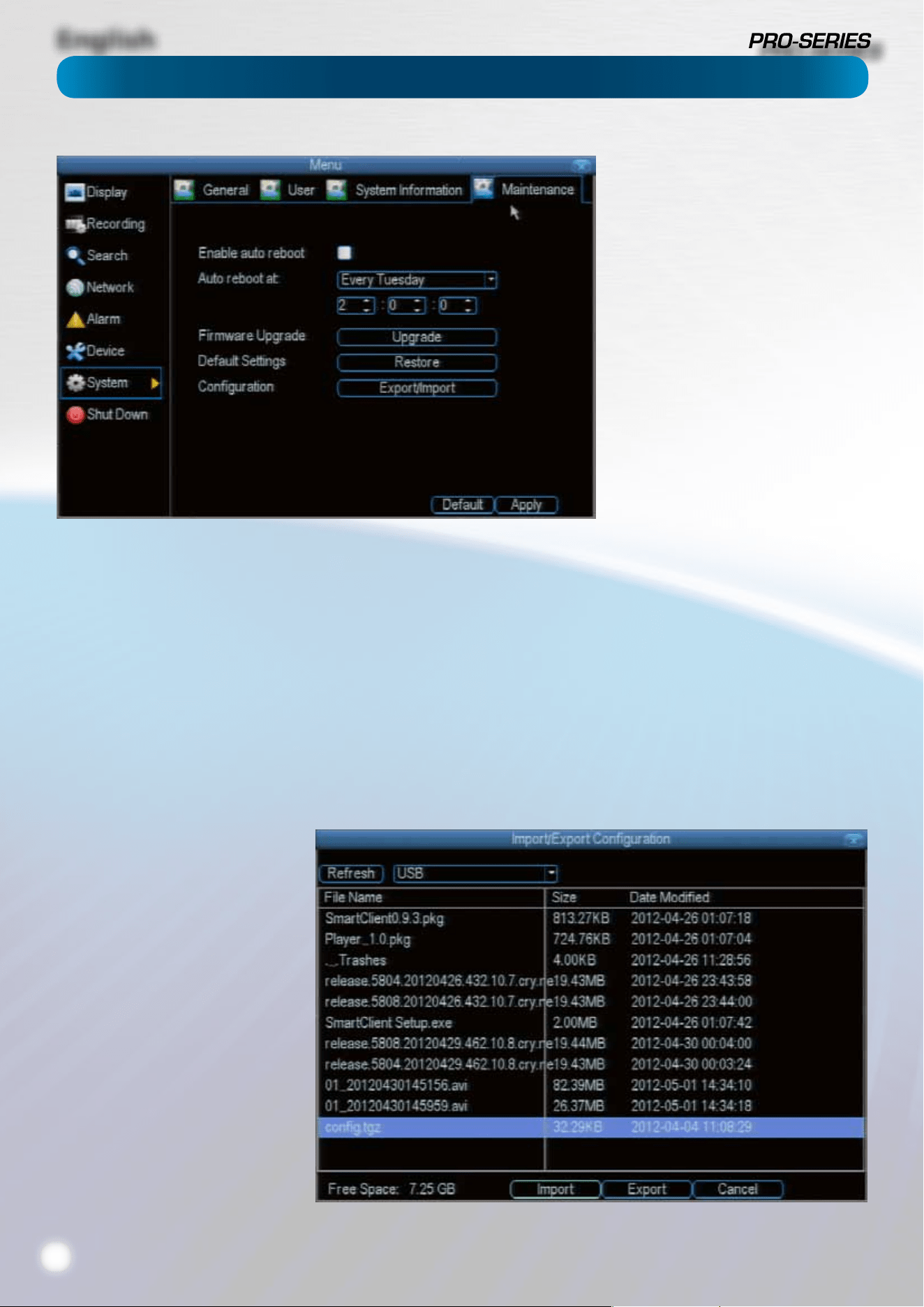
English
34
To maintain the operational integrity
of the DVR, it is suggested that it
be rebooted periodically. In much
the same way that a computer can
become unstable if left on for an
extremely long time, the DVR can
become unstable. It is strongly
suggested that the DVR be rebooted
at least once per month.
However, as this can be a hassle
(particularly if the DVR is stashed
away somewhere inconvenient) you
can set the DVR up to reboot itself.
Enable auto reboot: Will
automatically shut the DVR down
and restart it at a certain time of the
day or week.
Auto reboot at: Choose when you’d
like the DVR to reboot. Typically,
this will be a time when it’s unlikely
there’ll be any activity for the DVR to
record.
Firmware Upgrade (Upgrade): Instructs the DVR to update its rmware. You’ll only need to use this option if instructed to do
so by Swann Technical Support.
Default Settings (Restore): Loads the factory default settings.
This must be done after a rmware upgrade to ensure proper operation of the DVR. You can retain your settings, recording
schedule and so on by using the Import/Export Conguration function.
Conguration (Export): Creates a le containing all the settings you’ve customized, including your recording preferences,
schedule, user-list and so on.
To export your settings:
• Insert a USB ash drive into the USB port on the front of the DVR. Ensure it has enough free space (a few MB is sucient - the
le is less than 50KB) and that it is not write-protected.
• Choose Conguration: Import/Export.
• You’ll see a le browser, showing
the contents of the storage
device.
• Click Export to save your settings.
• Exporting your settings
will overwrite any previous
settings you’ve saved to that
ash drive. If you want to do
sequential conguration exports,
you’ll need multiple USB drives
- or, rename the le using a PC
(advanced users only).
Conguration (Import): Operates in
the same way as the Export function,
but is used to load a previously saved
conguation le.
Locate the le you want on your ash
drive - it will be called cong.tgz.
Loading the le will cause the DVR to
automatically reboot.
System: Maintenance
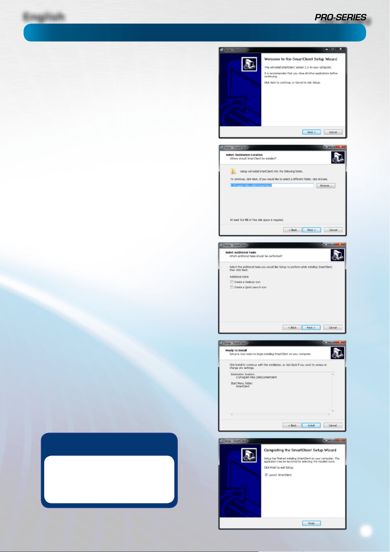
English
35
Your DVR comes with powerful remote access and interface
software, called MyDVR.
The MyDVR software will allow you to:
• view images from your DVR in real-time,
• playback recorded footage,
• copy footage to your local PC and
• adjust settings and congure the DVR.
In fact, the MyDVR software is so powerful, you don’t even
need to connect a monitor to the DVR if there’s a computer on
the local network that you’re running MyDVR on.
For quick and easy conguration of the DVR’s settings,
recording quality and schedule, we suggest using the
remote interface in MyDVR.
How to install MyDVR:
• Insert the included CD into your computer.
• Locate the le called MyDVR.exe and run this le.
• You may be asked by UAC (User Account Control) to allow
MyDVR to “make changes” to your system. Select Allow or
Continue.
• You’ll see an installation wizard. Simply follow the prompts
to install the software.
• Once the MyDVR software has been installed, it should
automatically detect your DVR on your network.
Minimum PC Requirements:
2.0GHz or faster CPU (Dual-core recommended)
1GB or more RAM (2GB recommended)
10/100Mbps Network (1000Mbps recommended)
Internet connection (512kbps+ recommended)
Supported Operating Systems
Microsoft Windows XP, Microsoft Windows Vista, Microsoft
Windows 7
NOTE: Windows XP, Windows Vista and Windows 7
are registered trademarks of Microsoft Corporation.
Remote Access: Installing MyDVR on PC
Got a Mac?
Check out
www.swann.com/mydvrmac
for the latest Mac-based remote
access software.
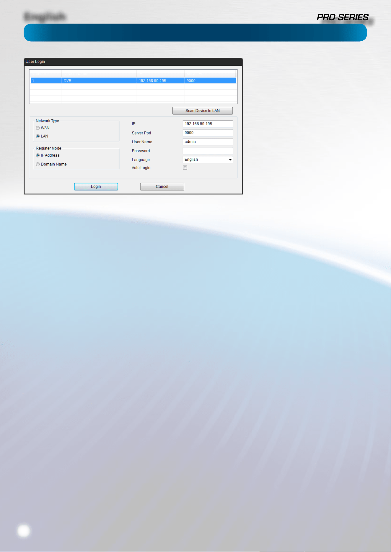
English
36
Before running MyDVR for the rst time:
Ensure your DVR is connected to a network and (if accessing
via the Internet) you know the Public IP Address of the DVR
or the DDNS address (see “Network: Advanced: DDNS” on
“Network: Advanced: DDNS” on page 21 for more).
That your network is set to DHCP addressing or the DVR
has been congured to use STATIC addressing (see “Network:
General” on page 19).
That UPnP is enabled on your router (see your router’s
documentation to learn more).
If you’re accessing the DVR via a LAN (local network):
• Select LAN under the heading Network Type.
• Your DVR should automatically appear in the list of
compatible devices near the top of the window.
• If your DVR does not appear, choose Scan Device in LAN.
If this doesn’t work, then it indicates some kind of local
network fault.
• Select your DVR from the list - it will probably be the only
thing there, unless you’ve got another Swann DVR.
If you’re accessing the DVR via the Internet:
• Select WAN under the heading Network Type.
• If you’re using a Fixed Public IP address, choose IP
Address under Register Mode, and enter the IP address
into the space marked IP.
• If you’re using a DDNS hostname, choose Domain Name
under Register Mode, and enter the DDNS domain name
into the eld labeled Domain.
• If you’re using the SwannDVR DDNS service, your address
will be: yourDDNSname.swanndvr.net
• Enter the Server Port for the DVR (it won’t be able to
automatically detect this over the Internet - you’ll need
to remember it!).
• Enter your Username and Password.
• Choose Login.
If you’re logging in to the DVR for the
rst time via a local network, then use
the following settings:
• IP: This eld will self-populate when
you select a DVR from the list.
• Server Port: The default is 9000.
MyDVR will automatically detect the
server port of the DVR.
• Username: To get full control of the
DVR, use the default administrator
username: admin. You can create
other accounts, but the default is
always called admin.
• Password: The default admin account
has no password. Leave this blank, and
set a password later.
Remote Access: Login
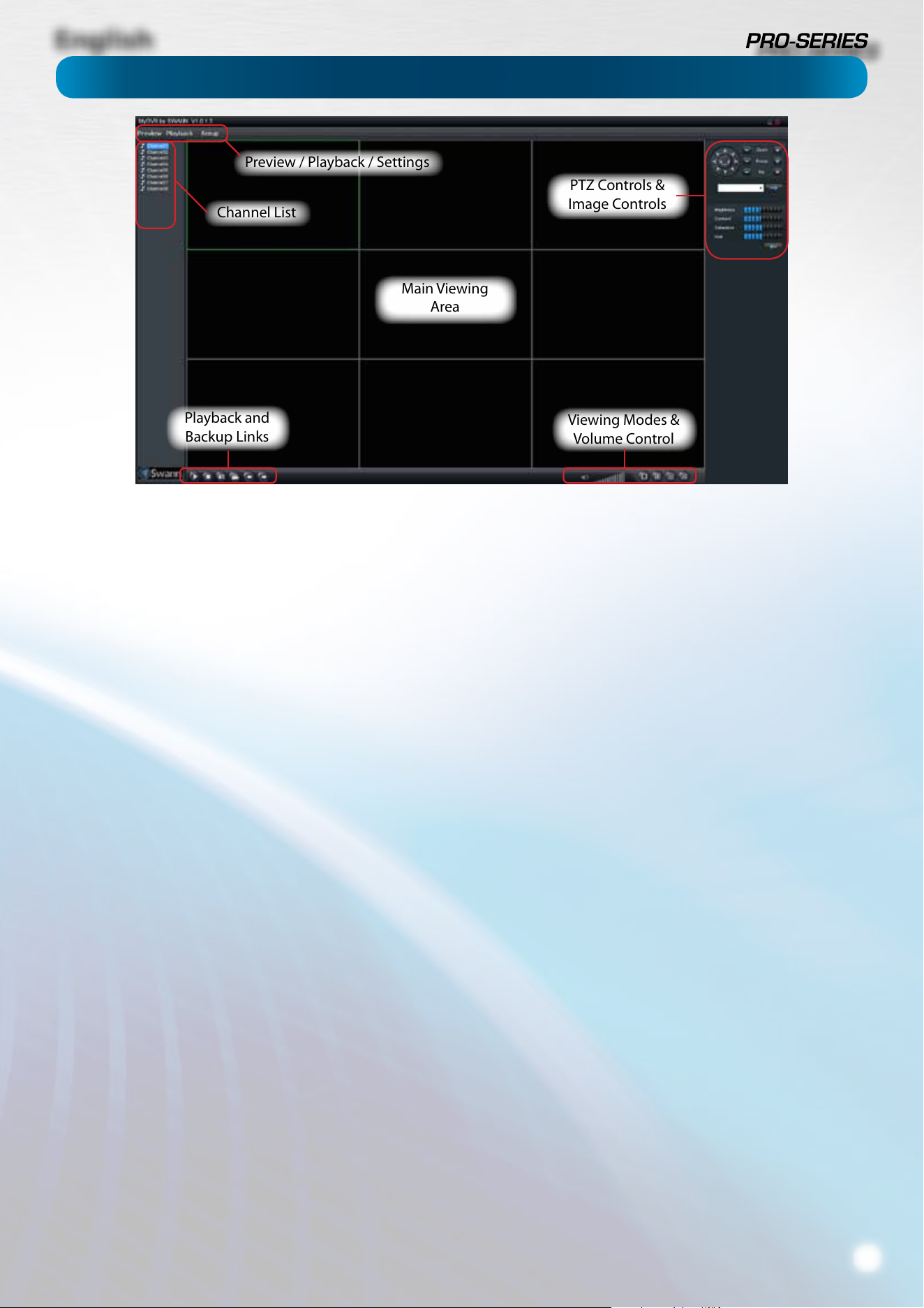
English
37
MyDVR: Interface
Preview: The default splash screen of MyDVR.
The screen layout emulates the multi-channel live view
screen of the DVR, showing you images coming directly from
your cameras in near-realtime (some delay is caused by the
network/Internet connection you’re using to access the DVR).
You can select a single camera, or multi-channel viewing by
using the Viewing Mode buttons in the lower right corner.
Playback: Opens the Playback interface, which operates in
much the same way as the playback interface on the DVR itself.
Settings (Conguration): Allows access to both the Local
Conguration screen and Remote Conguration menus.
Local Conguration: Denes how MyDVR will manage and
save footage/still images to your local PC.
Remote Conguration: Allows access to the DVR’s settings.
The congurable options are very similar to those you’ll nd
in the DVR menus.
Main Viewing Area: Where images from your camera will be
shown.
Playback / Backup Links: Quick access to playback and
backup.
PTZ Controls: For controlling PTZ devices. They operate in the
same way as those you’ll nd on the DVR itself.
Image Controls: You can alter the brightness, contrast,
saturation and hue of your images here. They operate in the
same way as those in the DVR’s menu (see “Camera: Display”
on page 11 for more information).
Viewing Modes: Choose between single camera viewing,
quad-mode (2 x 2, showing four cameras) and all (3 x 3
showing eight cameras - 8ch model only).
Volume Control: Alters how loud the audio output from the
DVR will be. Remember that the nal output volume will also
be aected by the master volume control of your operating
system, as well as the levels set on speakers or ampliers
connected to your system.
Main Viewing
Area
Playback and
Backup Links
Viewing Modes &
Volume Control
PTZ Controls &
Image Controls
Preview / Playback / Settings
Channel List
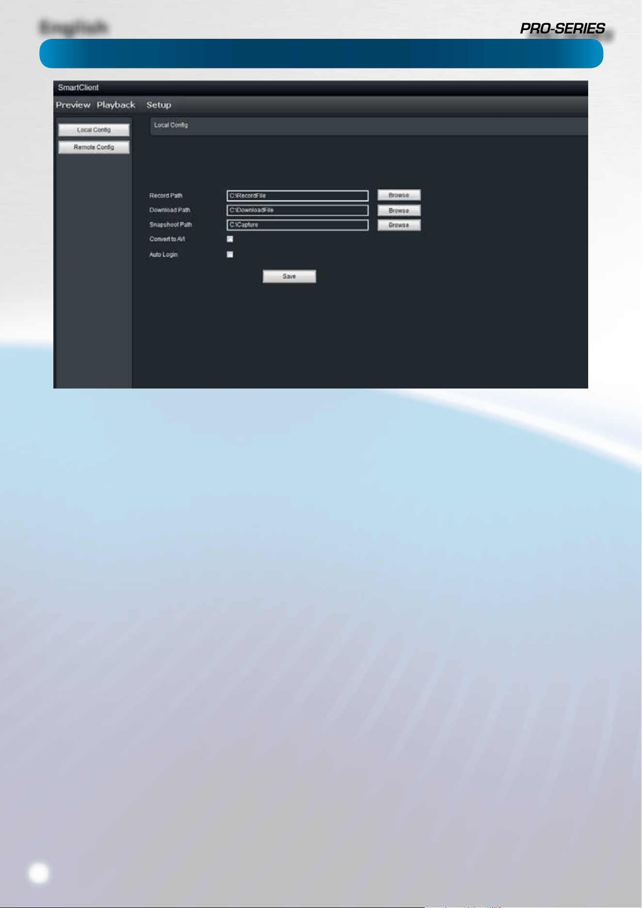
English
38
MyDVR: Local Conguration
The local conguration screen is where you can customise
how MyDVR will store and process footage on the local PC
when you download it from the DVR.
Record Path: Where MyDVR will save recordings if you select
Record from the Preview screen.
Download Path: Where MyDVR will save footage that you’ve
downloaded from the DVR.
Snapshot Path: Where MyDVR will save still images captured
using the snapshot function.
Convert to AVI: When selected, MyDVR will use your PC to
transcode footage from the DVR’s native format (H.264) into a
container that your computer (indeed, almost any computer)
will be able to playback without special software.
About transcoding to AVI:
Don’t be put o by the complex word - transcoding is just a
shortening of “translating code”.
Transcoding, while a straight-forward process, is very
processor intensive. You may notice signicant slow-down
on your computer while the transcoding takes place. For
best results, try not to over-burden your computer - just let it
transcode the footage in peace.
Auto-Login: When selected, MyDVR will automatically login
to and open the Preview screen for the DVR it is currently
connected to. Simply un-check Auto-Login if you don’t want
MyDVR to do this anymore, or you want to change the default
device (you’ll just need to go through the manual login
procedure once for the device you want).
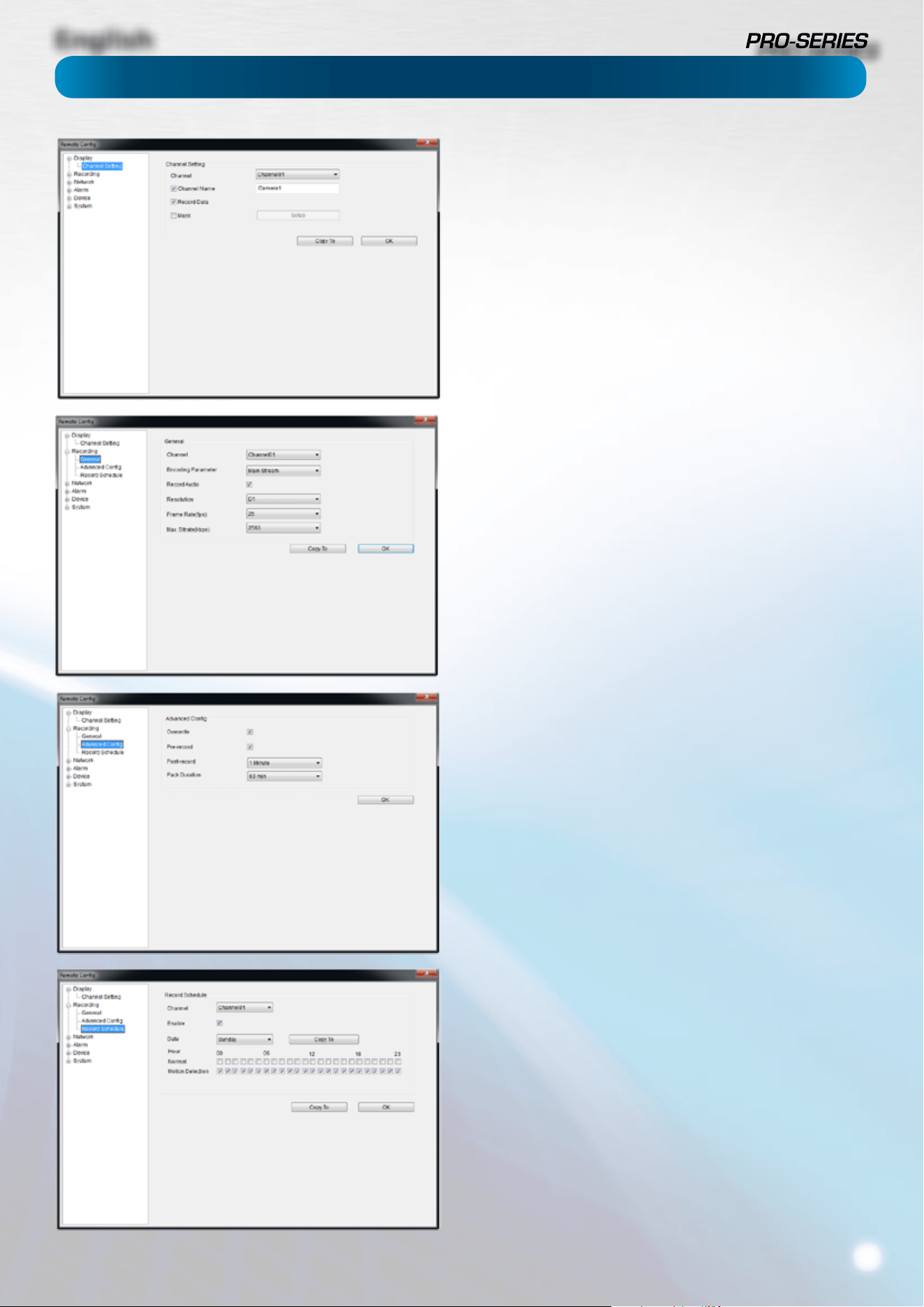
English
39
MyDVR: Remote Conguration
Display: Camera (see page 11)
Channel Name (Check Box): Whether the channel’s name will
be displayed on screen or not.
Channel Name: The title you’d like to give that camera.
Record Data: Whether the overlays (Channel Name, Date and
so on) will be recorded onto the video with your images.
Mask (Check Box): Turns the masking function on or o.
Mask (Setup): Creates a black privacy overlay which masks part
of your images. Will aect recordings.
Recording: General (page 13 for more)
Encoding Parameter: Choose from the main-stream or sub-
stream to congure.
Main Stream: The way the DVR will internally process and
record video.
Sub Stream: The way the DVR will encode and send video to a
remote device (such as the PC you’re using to access the DVR).
Record Audio (Check Box): Turn the audio recording function
on or o.
Resolution: How many pixels (little dots) make up your image.
From highest to lowest resolution: D1, HD1, CIF
Frame Rate: How many images per second the DVR will capture.
“Realtime” is 30fps (NTSC) or 25fps (PAL).
BitRate Limit: The maximum size that your video les will be.
The higher this is set, the better recordings will look - however,
they’ll also ll the hard drive faster.
Recording: Advanced Cong (see page 14)
Overwrite: Whether the DVR will erase old recordings to make
room for new ones, or not.
Pre-record: How long before an alarm event or motion the DVR
will record.
Delay: How long after an alarm event or motion the DVR will
continue to record for.
Pack Duration: The amount of video that will be stored as a
single “pack”.
Recording: Schedule (see page 15)
The schedule presented on-screen applies to one channel on
one specic day of the week only.
Use the Copy To functions to quickly assign identical schedule
layouts to multiple days/channels at once.
Be careful when programming your schedule. It’s one of the
most important aspects of setting up your DVR, and if it’s
wrong in any way, it could lead to disastrous complications
later.
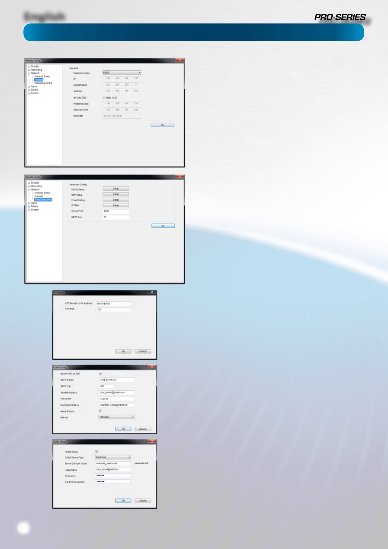
English
40
Network: General (see page 19 for more)
Be careful adjusting settings here - if the DVR can’t access the
network anymore, you won’t be able to congure it remotely!
Network Access: How your network is addressed - either DHCP
or STATIC IP addressing.
Subnet Mask: A required additional piece of IP addressing
information.
Gateway: The way “out” of your network, to the Internet.
Auto DNS / Static DNS: Whether the DVR will automatically
select a DNS server, or use one you assign.
Preered / Alternate DNS: The DVR has two DNS servers,
essentially a primary and a backup.
MAC Address: The Media Access Control address. For some
advanced networking, it can help to know this value.
Network: Advanced Cong (see page 20)
DDNS Setup: Opens the DDNS setup window (below).
NTP Setup: Opens the Network Time Protocol setup window
(see below).
Email Setting: Opens the Email Setup window (see below).
Server Port: One of the two ports the DVR needs to
communicate over your network. Ensure nothing else uses this
port. The default value is 9000. This is the port used for remote
access from a mobile device.
HTTP Port: The second of two ports the DVR needs to
communicate over your network. Ensure nothing else uses this
port. The default value is 85. This is the port number you’ll use
when logging in over the Internet from the MyDVR software.
• NTP Setup (see page 21)
NTP Domain or IP Address: The server you intend to use to
access the current date and time. The default is pool.ntp.org.
NTP Port: The port that the NTP server uses. The default for
pool.ntp.org is 123.
• Email Setting (see page 23)
Operates in the same way as the email setup menu in the DVR
menu. Rather than attempt to summarize here, it’s easier to
simply turn back to page 23 to learn more.
• DDNS Setup (see page 21)
Where you can congure a Dynamic DNS server to track the
“position” of your DVR over the Internet. Check out page 21
for more information on DDNS servers.
We recommend using SWANNDVR as your DNS service.
This is a free service for Swann DVR owners, which we directly
support.
To create an account with SWANNDVR, go to:
http://mydvr.swanndvr.com/
and click the Registration button. Follow the prompts to create
your account.
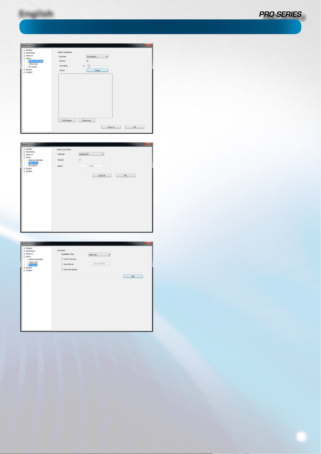
English
41
Alarm: Motion Detection (see page 24)
Channel: The channel you’re conguring the motion detection
settings for.
Enable: Whether the motion detection is enabled for the
channel currently selected.
Sensitivity: A sliding scale between 1 and 50
Action: What you’d like the DVR to do when it detects motion.
Typically (assuming the schedule is congured to do so) this will
be to record video. It can also be a cue to trigger an email alert,
or to sound the DVR’s internal buzzer.
Alarm: Video Loss (see page 27)
Action (Check boxes): Whether you’d like the DVR to send an
email alert or to sound the DVR’s internal buzzer.
Arm Schedule: The times of day/week you’d like the DVR to be
“armed” to detect video loss.
Alarm: Exception (see page 27)
Exception Type: The
Audio Warning: Sounds the DVR’s internal buzzer.
Send Email: Commands the DVR to send an email alert.
Show Exception: Shows any alerts that occur at the bottom
right corner of the main screen. Double-click on the alert
notication to see details.
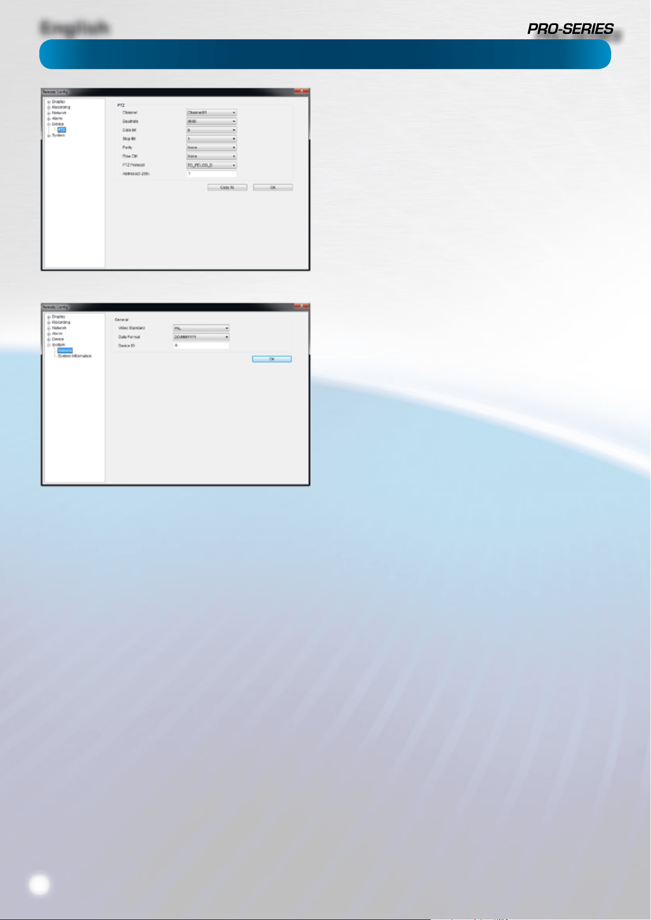
English
42
Device: PTZ (see page 30)
Channel: The channel you’d like to congure a PTZ camera for.
Settings: See page 30 for more information about the PTZ
settings you’ll nd here.
You’ll probably need the documentation that came with your
PTZ camera to gure out how to ll out this conguration
page.
System: General (see page 31)
System Standard: Lets you change the DVR between PAL or
NTSC standards.
NTSC operates at 30 frames per second, and has an eective
resolution of 720 x 480. It’s used in countries with 60Hz power,
such as the United States, Canada, Japan and so on.
PAL operates at 25 frames per second, and has a eective
resolution of 720 x 576. It’s used in countries with 50Hz power,
such as most of Europe, the United Kingdom and Australia.
If this is not set correctly, images on your DVR may be black
and white, ickering or simply not there at all.
If you change the System Standard,
it automatically forces a reboot of the DVR.
This will happen the instant you click OK.
Date Format: How you’d like the date displayed.
Device ID: A code dierentiating this DVR from other DVRs or
DVR-like devices. You can leave this setting - it’s only important
if you’re got multiple DVR’s and you’re planning to use them on
the same network or share PTZ device control.

English
43
Remote Access From a Mobile Device
Using the SwannView app for mobile devices, you’ll be able to log into your DVR from almost anywhere you can imagine (or,
at least, get a decent signal - like everyone, we’re at the mercy of your phone company!) and view images coming from your
cameras in real-time (or as close to as wireless networking will permit).
How cool is that? We’re pretty sure this was science-ction just a few short years ago.
You’ll need a compatible mobile device. At the time of writing, there are apps for iOS (iPhone / iPad) and Android-based devices.
We’re working on apps for other mobile platforms.
To download the latest mobile viewing apps, operating guides and to check the compatibility of your device, log onto:
www.swann.com/swannview

English
44

English
45

English
46
Troubleshooting
Get up to Date Information
We’re constantly making improvements to our products, rmware, software, user manuals, video
tutorials and more.
To ensure you’re up to date with the latest documentation for your DVR, check out our website:
www.swann.com/trueblu

English
47
Warranty Information
Warranty Terms & Conditions
Swann Communications warrants this product against defects in workmanship and material for a period
of one (1) year from its original purchase date. You must present your receipt as proof of date of purchase
for warranty validation. Any unit which proves defective during the stated period will be repaired without
charge for parts or labor or replaced at the sole discretion of Swann. The end user is responsible for all
freight charges incurred to send the product to Swann’s repair centers. The end user is responsible for all
shipping costs incurred when shipping from and to any country other than the country of origin.
The warranty does not cover any incidental, accidental or consequential damages arising from the use of
or the inability to use this product. Any costs associated with the tting or removal of this product by a
tradesman or other person or any other costs associated with its use are the responsibility of the end user.
This warranty applies to the original purchaser of the product only and is not transferable to any third
party. Unauthorized end user or third party modications to any component or evidence of misuse or
abuse of the device will render all warranties void.
By law some countries do not allow limitations on certain exclusions in this warranty. Where applicable by
local laws, regulations and legal rights will take precedence.
For Australia: Our goods come with guarantees which cannot be excluded under Australian Consumer
Law. You are entitled to a replacement or refund for a major failure and for compensation for any other
reasonably foreseeable loss or damage. You are also entitled to have the goods repaired or replaced if the
goods fail to be of acceptable quality and the failure does not amount to major failure.
USA
Swann Communications USA Inc.
12636 Clark Street
Santa Fe Springs CA 90670
USA
Australia
Swann Communications
Unit 13, 331 Ingles Street,
Port Melbourne Vic 3207
Australia
United Kingdom
Swann Communications LTD.
Stag Gates House
63/64 The Avenue
SO171XS
United Kingdom

English
48
USA toll free
1-800-627-2799
(Su, 2pm-10pm US PT)
(M-Th, 6am-10pm US PT)
(F 6am-2pm US PT)
USA Exchange & Repairs
1-800-627-2799 (Option 1)
(M-F, 9am-5pm US PT)
AUSTRALIA toll free
1300 138 324
(M 9am-5pm AUS ET)
(Tu-F 1am-5pm AUS ET)
(Sa 1am-9am AUS ET)
NEW ZEALAND toll free
0800 479 266
UK
0203 027 0979
Helpdesk / Technical Support Details
Swann Technical Support
All Countries E-mail: [email protected]
Telephone Helpdesk
© Swann Communications 2012