2
Hardware Installation Guide
Guide d’installation du matériel
Guía de instalación de hardware
To start using your DVR, you need the following:
1. A high-definition TV capable of displaying 720p or 1080p video.
2. A router with a broadband internet connection.
3. A mobile device (Android or iOS) to download the mobile app.
Español
Para comenzar a utilizar el DVR, necesita lo siguiente:
1. Un televisor de alta definición con capacidad para mostrar video 720p
o 1080p.
2. Un enrutador con una conexión de Internet de banda ancha.
3. Un dispositivo móvil (Android o iOS) para descargar la aplicación móvil.
Français
Pour commencer à utiliser votre DVR, vous avez besoin des éléments
suivants:
1. Une TV haute définition capable d’afficher une vidéo de 720p ou 1080p.
2. Un routeur avec une connexion internet à large bande.
3. Un appareil mobile (Android ou iOS) pour télécharger l’application mo-
bile.
QH_48CH_5580N_4KRLGL_031220 | © Swann 2020
3 4
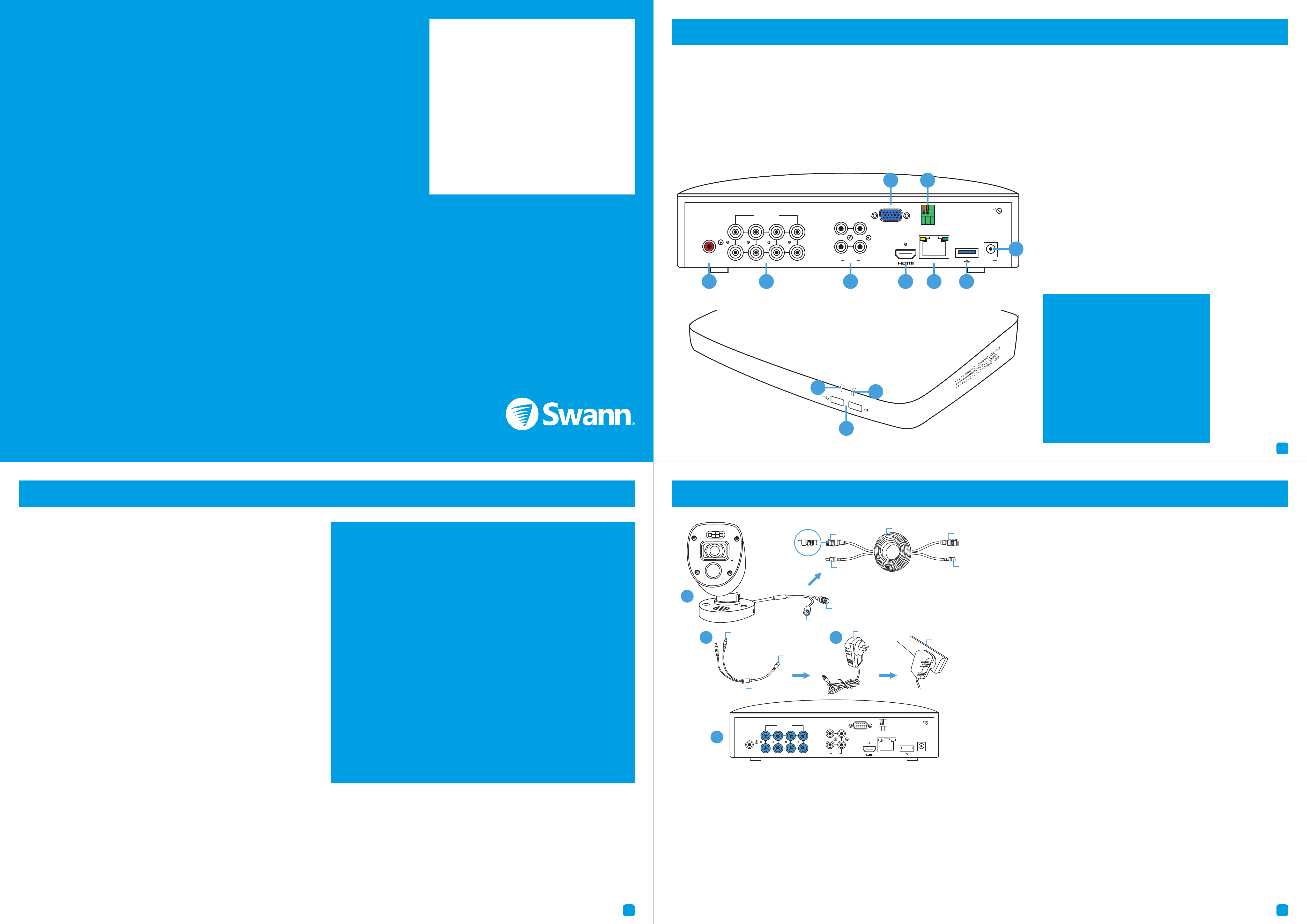
1. Audio Output: For connecting to a stereo or amplifier. This
is not required when using the HDMI port.
2. Camera Inputs: Connect your cameras here. Twist the
video connection to lock it in place.
3. Audio Inputs: For connecting one or more microphones
to record audio (the microphone must have its own power
source).
4. VGA Port: Connect this to your monitor with a VGA input
(VGA cable not supplied). This is not required when using
the HDMI port.
5. HDMI Port: Connect this to your TV with a HDMI input
(HDMI cable supplied).
6. PTZ Port: For connecting RS-485 compatible devices.
7. Ethernet Port: Connect this to your router so your DVR
can connect to the internet (Ethernet cable supplied).
8. USB Port: Connect a USB flash drive to copy recorded
events and to perform a firmware upgrade.
9. Power Port: Connect the 12V power adapter here.
10. Power LED: Indicates your DVR has power.
11. Hard Drive LED: Flashes when the hard drive is active.
12. USB Ports: Connect the mouse to one of the ports.
Español
1. Conecte la salida de vídeo y las conexiones de
entrada de alimentación de la cámara a los cables
de vídeo y de alimentación.
2. Conecte el divisor al otro extremo del cable de
vídeo y de alimentación. Esto alimentará varias
cámaras con un solo adaptador de corriente.
3. Conecte el otro extremo del divisor al adaptador
de corriente y luego conecte el adaptador de
corriente a una toma de corriente.
4. Conecte la salida de vídeo en el cable de vídeo y
alimentación a cada entrada de su DVR.
Français
1. Conecte la salida de vídeo y la entrada de
alimentación de la cámara a las conexiones del
cable de vídeo y alimentación.
2. Conecte el divisor de potencia al otro extremo
del cable de vídeo y de alimentación.
3. Conecte el otro extremo del divisor de potencia
al adaptador de alimentación y, a continuación,
conéctelo a la alimentación.
4. Conecte la salida de vídeo en el cable de vídeo y
alimentación a las entradas de su DVR.
1. Audio Output
2. Camera Inputs
3. Audio Inputs
4. VGA Port
5. HDMI Port
6. PTZ Port
7. Ethernet Port
8. USB Port
9. Power Port
10. Power LED
11. Hard Drive LED
12. USB Ports
1. Keep your DVR free from obstructions to
maintain optimal operating temperature.
1. Mantenga su DVR libre de obstrucciones
para mantener la temperatura óptima.
1. Gardez votre DVR libre d’obstructions pour
maintenir la température optimale.
2. Some of the connections illustrated may
differ with your DVR model.
2. Algunas de las conexiones ilustradas
pueden diferir con su modelo DVR.
2. Certaines des connexions peuvent différer
avec votre modèle DVR.
This installation guide will assist you on getting your DVR up and running as soon as possible. To make sure nothing was
damaged during shipping, we recommend that you connect everything and try it before you do a permanent installation.
Español: Esta guía le ayudará a conseguir su DVR funcionando tan pronto como sea posible. Para asegurarse de que nada
se dañó durante el envío, le recomendamos que conecte todo y lo pruebe antes de realizar una instalación permanente.
Français: Ce guide vous aidera à mettre votre DVR en marche dès que possible. Pour s’assurer que rien n’a été endommagé
pendant l’expédition, nous vous recommandons de tout connecter pour essayer avant de faire une installation permanente.
Step/Paso/Étape: 1 (8 Channel model illustration shown)
Step/Paso/Étape: 2
FCC Warning Statement:
This device complies with part 15 of the FCC Rules.
Operation is subject to the following two conditions: (1)
This device may not cause harmful interference and (2) this
device must accept any interference received, including
interference that may cause undesired operation.
Battery Safety Information:
This product contains a coin/button cell battery. If the cell
battery is swallowed, it can cause severe internal burns
and can lead to death. Keep away from babies and small
children at all times.
• If the battery is swallowed or placed inside any part of
the body, immediately seek medical help
• Risk of explosion if incorrect battery is used
• Dispose of used battery properly
Step/Paso/Étape: 3 (8 Channel model illustration shown)
1. Connect the video output and power input connections on the
camera to the corresponding connections on the video & power cable.
2. Connect the power splitter to the other end of the video & power
cable. This will power multiple cameras using a single power adapter.
3. Connect the other end of the power splitter to the power adapter
then connect the power adapter to a spare power outlet.
4. Connect the video output on the video & power cable to each camera
input on your DVR. Twist the connection to lock it in place.
1
2 3
Power Input
Video Output
Twist to lock
connectors
Video Input
Video & Power Cable
Connect this to your DVR
Power Splitter
connects here
Power Output
Power Adapter
connects here
Power Splitter
Power Adapter
Video & Power Cable
connects here
Connect to a spare
power outlet
4
1
3
2
8 7 6 5
4 1
VIDEO INPUTVIDEO INPUT
AUDIO
INPUT
AUDIO
INPUT
3 1
4 2
VGAVGA
LANLAN
12V12V
RS485RS485
AUDIO
OUTPUT
AUDIO
OUTPUT
HDD
PWR
11
12
2
4
8
10
3
2
8 7 6 5
4 1
VIDEO INPUTVIDEO INPUT
AUDIO
INPUT
AUDIO
INPUT
3 1
4 2
VGAVGA
LANLAN
12V12V
RS485RS485
AUDIO
OUTPUT
AUDIO
OUTPUT
1 3 5
6
7
9
5 6
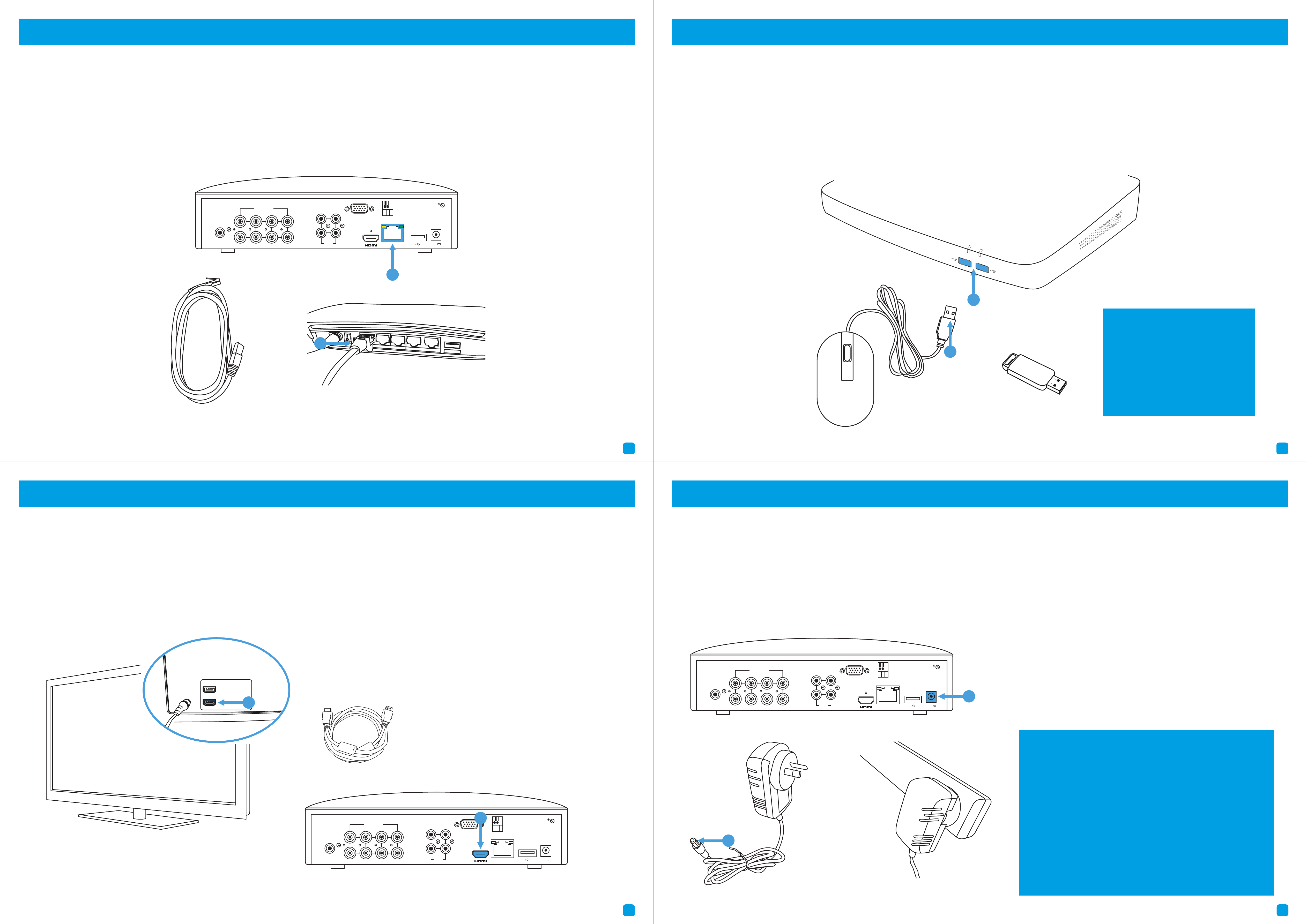
Connect to your Home Network: Connect the supplied Ethernet cable to the Ethernet port (1) on your DVR then connect
the other end to a spare port (2) on your router or Wi-Fi access point. Don’t proceed to the next step until this is done.
Conéctese a su red: Conecte el cable Ethernet suministrado al puerto Ethernet (1) en su DVR y luego conecte el otro
extremo a un puerto de repuesto (2) en su router. No proceda al siguiente paso hasta que esto se haga.
Connexion à votre réseau: Branchez le câble Ethernet fourni au port Ethernet (1) de votre DVR, puis branchez l’autre
extrémité à un port de secours (2) sur votre routeur. Ne passez pas à l’étape suivante jusqu’à ce que cela soit fait.
7 8
2
Connect your Mouse: Connect the supplied mouse (1) to one of the available USB ports (2) located at the front. To copy
events and to perform a firmware upgrade, connect a USB flash drive (not supplied) to the other port.
Conecte el ratón: Conecte el ratón (1) a uno de los puertos USB disponibles (2) situados en la parte delantera. Para copiar
eventos y realizar una actualización de firmware, conecte una unidad flash USB (no suministrado) al otro puerto.
Connectez votre souris: Connectez la souris (1) à l’un des ports USB disponibles (2) situés à l’avant. Pour copier des
événements et effectuer une mise à niveau du micrologiciel, connectez un lecteur flash USB (non fourni) à l’autre port.
HDMI IN 1
HDMI IN 2
2
Connect to your TV: Connect the supplied HDMI cable to the HDMI port (1) then connect the other end to a spare HDMI
input (2) on your TV. Press the A/V button on your TV’s remote to select the HDMI input.
Conéctese a su televisor: Conecte el cable HDMI suministrado al puerto HDMI (1) y luego conecte el otro extremo a una
entrada HDMI (2) en su televisor. Pulse el botón A/V del mando a distancia del televisor para seleccionar la entrada HDMI.
Connectez-vous à votre téléviseur: Branchez le câble HDMI sur le port HDMI (1), puis branchez l’autre extrémité à une
entrée HDMI (2) sur votre téléviseur. Appuyez sur le bouton A/V de votre télécommande pour sélectionner l’entrée HDMI.
Connect your Power Adapter: Connect the supplied power adapter’s power connection (1) to the power input (2) on your
DVR first (to minimize sparking). Connect the power adapter to a power outlet to supply power.
Conecte el adaptador de corriente: Conecte la conexión de alimentación del adaptador de alimentación (1) a la entrada
de alimentación (2) en su DVR primero y luego conecte el adaptador de corriente a una toma de corriente.
Branchez votre adaptateur d’alimentation: Branchez l’adaptateur d’alimentation (1) à l’entrée d’alimentation (2) de votre
DVR, puis branchez le bloc d’alimentation à une prise de courant.
1
You will see the Startup Wizard displayed. Follow
the “Startup Wizard Quick Start Guide” (the red
coloured guide) to configure and setup your DVR.
Debe ver el asistente visualizado. Siga la “Guía
de inicio rápido del asistente” (la guía de color
rojo) para configurar y programar su DVR.
Vous devriez voir l’Assistant affiché. Suivez le
“Guide de démarrage de l’Assistant” (le Guide
de couleur rouge) pour configurer et installer
votre DVR.
Step/Paso/Étape: 4 (8 Channel model illustration shown) Step/Paso/Étape: 5
Step/Paso/Étape: 6 (8 Channel model illustration shown) Step/Paso/Étape: 7 (8 Channel model illustration shown)
HDD
PWR
2
1
Compatible with USB flash
drives up to 128GB.
Compatible con unidades
flash USB de hasta 128 GB.
Compatible avec USB flash
conduit jusqu’à 128 Go.
3
2
8 7 6 5
4 1
VIDEO INPUTVIDEO INPUT
AUDIO
INPUT
AUDIO
INPUT
3 1
4 2
VGAVGA
LANLAN
12V12V
RS485RS485
AUDIO
OUTPUT
AUDIO
OUTPUT
1
3
2
8 7 6 5
4 1
VIDEO INPUTVIDEO INPUT
AUDIO
INPUT
AUDIO
INPUT
3 1
4 2
VGAVGA
LANLAN
12V12V
RS485RS485
AUDIO
OUTPUT
AUDIO
OUTPUT
1
3
2
8 7 6 5
4 1
VIDEO INPUTVIDEO INPUT
AUDIO
INPUT
AUDIO
INPUT
3 1
4 2
VGAVGA
LANLAN
12V12V
RS485RS485
AUDIO
OUTPUT
AUDIO
OUTPUT
2
