1
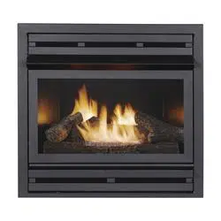
VENT-FREE FIREPLACE INSERT
INSTALLER: Leave this manual with the appliance.
CONSUMER: Retain this manual for future reference.
WARNING: IF THE INFORMATION IN THIS MANUAL IS NOT FOLLOWED
EXACTLY, A FIRE OR EXPLOSION MAY RESULT CAUSING PROPERTY
DAMAGE, PERSONAL INJURY OR LOSS OF LIFE.
CAUTION - FOR YOUR SAFETY
Questions, problems, missing parts? Before returning to your retailer, call our customer
service department at 1-877-447-4768, 8:30 a.m. – 4:30 p.m., CST, Monday – Friday or
email us at [email protected].
WARNING: This appliance
is equipped for (Natural or Pro-
pane) gas. Field conversion is
not permitted.
- Do not store or use gasoline or other ammable vapors and Iiquids in vicinity of this or
any other appliance.
WHAT TO DO IF YOU SMELL GAS
• Do not try to light any appliance.
• Do not touch any electrical switch; do not use any phone in your building.
• Immediately call your gas supplier from a neighbor’s phone. Follow the gas supplier’s
instructions.
• If you cannot reach your gas supplier, call the re department.
- Installation and service must be performed by a qualied installer, service agency or the
gas supplier.
This is an unvented gas-red heater. It uses air (oxygen) from the room in which it is
installed. Provisions for adequate combustion and ventilation air most be provided.
Refer to Air For Combustion and Ventilation section on page 8-10 of this manual.
This appliance may be installed in an aftermarket, permanently located manufactured (mobile)
home, where not prohibited by local codes.
This appliance is only for use with the type of gas indicated on the rating plate.
This appliance is not convertible for use with other gases.
80-10-565 - 2020-06-04
Propane
PHZCI28LP
PHZCI32LP
Natural Gas
PHZCI28NG
PHZCI32NG
ANS Z21.11.2-2019
Models:

2
WARNING: Read the Installation & Operating Instructions before using this appliance.
IMPORTANT: Read all instructions and warnings carefully before starting installation.
Failure to follow these instructions may result in possible injury to persons or a re
hazard and will void the warranty.
TABLE OF CONTENTS
Specications ................................................................................................................................... 2
Important Safety Information ............................................................................................................3
Product Identication ........................................................................................................................ 5
Product Features .............................................................................................................................. 6
Unpacking......................................................................................................................................... 6
Preparing for Installation................................................................................................................... 8
Installation ...................................................................................................................................... 11
Operation ........................................................................................................................................ 23
Remote Control Operation...............................................................................................................25
Care and Maintenance ................................................................................................................... 32
Troubleshooting .............................................................................................................................. 35
Replacement Parts ......................................................................................................................... 37
Accessories .................................................................................................................................... 38
Warranty ......................................................................................................................................... 40
SERVICE HINTS
When Gas Pressure Is Too Low
• pilot will not stay lit
• burners will have delayed ignition
• replace will not produce specied heat
• for propane/LP units, propane/LP gas supply may be low
You may feel your gas pressure is too low. If so, contact your local natural or propane/LP gas supplier.
Model PHZCI28LP Series PHZCI32LP Series
Input Rating 27,500 BTU 32,000 BTU
MIN Input Rating 25,000 BTU 29,000 BTU
Gas Type LP LP
Manifold Pressure 10’’ WC 10’’ WC
Max. Inlet Pressure 14’’ WC 14’’ WC
Min. Inlet Pressure 11’’ WC 11’’ WC
Model PHZCI28NG Series PHZCI32NG Series
Input Rating 27,500 BTU 32,000 BTU
MIN Input Rating 20,500 BTU 24,000 BTU
Gas Type NG NG
Manifold Pressure 5’’ WC 5’’ WC
Max. Inlet Pressure 14’’ WC 14’’ WC
Min. Inlet Pressure 7’’ WC 7’’ WC
3
IMPORTANT: Read this owner’s manual carefully and completely before trying to assemble, operate,
or service this heater. Improper use of this heater can cause serious injury or death from burns, re,
explosion, electrical shock, and carbon monoxide poisoning.
IMPORTANT SAFETY INFORMATION
WARNING: Installation and repair should be done by a qualied service person. The appliance
should be inspected before use and at least annually by a professional service person. More frequent
cleaning may be required due to excessive lint from carpeting, bedding material, etc. It is imperative
that control compartments, burners, and circulating air passageways of the appliance be kept clean.
WARNING: Do not store or use gasoline or other ammable vapors or liquids in the vicinity of or
any other appliance.
CARBON MONOXIDE POISONING: Early signs of carbon monoxide poisoning resemble the u with
headaches, dizziness, or nausea. If you have these signs, the heater may not be working properly. Get
fresh air immediately! Have heater serviced. Some people are more affected by carbon monoxide than
others. These include pregnant women, people with heart or lung disease, people who are
anemic, those under the inuence of alcohol, and those living in high altitudes.
NATURAL AND PROPANE/LP GAS: Natural and Propane/LP gases are odorless. An odor-making
agent is added to the gas. The odor helps you detect a gas leak. However, the odor added to the gas
can fade. Gas may be present even though no odor exists. Make certain you read and understand all
warnings. Keep this manual for reference. It is your guide to operating this heater safely.
WARNING: Any change to this replace/heater or its controls can be dangerous.
WARNING: Do not use a blower insert, heat exchanger insert or other accessory not ap
proved for use with this heater.
WARNING: Children and adults should be alerted to the hazard of high surface temperature and
should stay away to avoid burns or clothing ignition.
WARNING: Heater becomes very hot when operating. Keep children and adults away from hot
surfaces to avoid burns or clothing ignition. Heater will remain hot for a time after shutoff. Allow
surfaces to cool before touching.
WARNING: Keep the appliance area clear and free from combustible materials, gasoline, and
other ammable vapors and liquids.
WARNING: Due to high temperatures, locate this appliance out of trafc and away from
furniture and draperies.
WARNING: Do not place clothing or other ammable material on or near the appliance. Never
place any objects in the heater.
WARNING: Do not allow fans to blow directly into replace. Avoid drafts that alter burner ame
patterns.
WARNING: Carefully supervise young children when they are in the room with the heater.
WARNING: Any safety screen,guard, or barrier removed for servicing an appliance must be
replaced prior to operating the heater.
WARNING: Solid fuels are not to be used in the replace.
WARNING: This appliance can be used with propane or natural gas.
WARNING
This product can expose you to chemicals including Benzene which is known to the State of California
to cause cancer and reproductive harm.
For more information go to www.p65Warnings.ca.gov

4
SAFETY INFORMATION
1. This appliance is only for use with the type of gas indicated on the rating plate. This appliance is
not convertible for use with other gases.
2.
Do not place propane/LP supply tank(s) inside any structure. Locate propane/LP supply tank(s) outdoors.
3. If you smell gas
• shut off gas supply
• do not try to light any appliance
• do not touch any electrical switch; do not use any phone in your building
• immediately call your gas supplier from a neighbor’s phone. Follow the gas supplier’s instructions
• if you cannot reach your gas supplier, call the re department
4. This replace shall not be installed in a bedroom or bathroom.
5. Do not use this replace as a wood-burning replace. Use only the logs provided with the replace.
6. Do not add extra logs or ornaments such as pine cones, vermiculite or rock wool. Using these
added items can cause sooting. Do not add lava rock around base. Rock and debris could fall into
the control area of replace. When servicing, always replace screen before operating heater.
7. This replace is designed to be smokeless. If logs ever appear to smoke, turn off replace and
call a qualied service person. Note: During initial operation, slight smoking could occur due to log
curing and replace burning manufacturing residues.
8. To prevent the creation of soot, follow the instructions in Cleaning and Maintenance, page 32.
9. Before using furniture polish, wax, carpet cleaner or similar products, turn replace off. If heated,
the vapors from these products may create a white powder residue within burner box or on adjacent
walls or furniture.
10. This replace needs fresh air ventilation to run properly. This replace has an Oxygen Depletion
Sensing (ODS) safety shutoff system. The ODS shuts down the replace if not enough fresh air is
available. See Air for Combustion and Ventilation, page 9-11. If replace keeps shutting off, see
Troubleshooting, page 34.
11. Do not run replace
• where ammable liquids or vapors are used or stored.
• under dusty conditions.
12. Do not use this replace to cook food or burn paper or other objects.
13. Never place any objects in the replace or on logs.
14. Do not use replace if any part has been under water. Immediately call a qualied service technician
to inspect the room replace and to replace any part of the control system and any gas control which
has been under water.
15. Turn off and unplug replace and let cool before servicing. Only a qualied service person
should service and repair replace.
16. Operating replace above elevations of 4,500 feet could cause pilot outage.
17.
Do not operate replace if log is broken. Do not operate replace if log is chipped (dime-sized or larger).
18. To prevent performance problems, do not use propane/LP fuel tank of less than 100 lb. capacity.
19. Keep all air openings in front and bottom of heater clear and free of debris. This will ensure
enough air for proper combustion.
20. If heater shuts off do not relight until you have provided fresh outside air. If heater keeps shutting
off, have it serviced.
QUALIFIED INSTALLING AGENCY
Only a qualied agency should install and
replace gas piping, gas utilization equipment or
accessories, and repair and equipment servic-
ing. The term "qualied agency" means any
individual, rm, corporation, or company that
either in person or through a representative is
engaged in and is responsible for:
a) Installing, testing, or replacing gas piping or
b)Connecting, installing, testing, repairing, or
servicing equipment; that is experienced in
such work; that is familiar with all precautions
required; and that has complied with all the re-
quirements of the authority having jurisdiction.
5
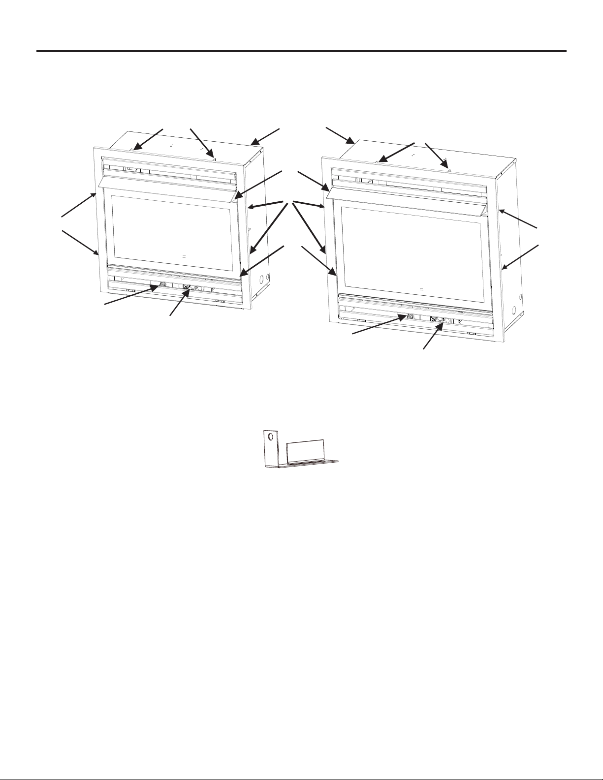
PRODUCT IDENTIFICATION
Fig. 1 - Vent-Free Fireplace Insert
PHZCI28LP
PHZCI28NG
PHZCI32LP
PHZCI32NG
Ignitor Button
Fireplace Insert Cabinet
Control Knob
Screen
Ignitor Button
Hood
Control Knob
Standos
Standos
Standos
Standos
Standos
Fig. 1.1 - Standoffs
QTY
6
6
Fig. 1.2 - Intermediate
Fig. 1.3 - Full Size
7
SAFETY PILOT
This heater has a pilot with an Oxygen Depletion Sensing (ODS) safety shutoff system.
The ODS/pilot shuts off the heater if there is not enough fresh air and cuts off main burner gas in the
event of ame out.
ELECTRIC PUSH BUTTON IGNITION SYSTEM
This heater is equipped with an electronic piezo control system. This system requires
one AAA battery (provided).
MILLIVOLT CONTROL SYSTEM
The millivolt controlled heater has both ON/OFF manual controls with HI/LO adjustable settings and
the option of adding a wall switch or thermostat with wire.
BLOWER KIT (OPTIONAL)
The blower kit helps to distribute the warmed air into the space more rapidly.
State of Massachusetts: The installation must be made by a licensed plumber or gas tter in the
Commonwealth of Massachusetts. Sellers of unvented propane or natural gas-red supplemental
room heaters shall provide to each purchaser a copy of 527 CMR 30 upon sale of the unit.
In the State of Massachusetts, unvented propane or natural gas-red space heaters shall
be prohibited in bedrooms and bathrooms.
In the State of Massachusetts the gas cock must be a T-handle type. The State of
Massachusetts requires that a exible appliance connector cannot exceed three feet in
length.
LOCAL CODES
Install and use heater with care. Follow all codes. In the absence of local codes, use the latest edi-
tion of The National Fuel Gas Code, ANSI Z223.1, also known as NFPA 54*.
*Available from:
American National Standard Institute, Inc. National Fire Protection Association, Inc.
1430 Broadway 1 Batterymarch Park
New York, NY 10018 Quincy, MA 02269-9101
This heater is designed for vent-free operation. State and local codes in some areas prohibit the use
of vent-free heaters.
PRODUCT FEATURES

8
PREPARING FOR INSTALLATION
AIR FOR COMBUSTION AND VENTILATION
WARNING: This heater shall not be installed in a room or space unless the required volume
of indoor combustion air is provided by the method described in the Nation Fuel Gas Code, ANSI
Z223.1/NFPA 54, the International Fuel Gas Code, or applicable local codes.
PRODUCING ADEQUATE VENTILATION
All spaces in homes fall into one of the three following ventilation classications:
1. Unusually Tight Construction
2. Unconned Space
3. Conned Space
The information on pages 8 through 10 will help you classify your space and provide adequate ventilation.
Conned and Unconned Space
A conned space as a space whose volume is less than 50 cu. ft. per 1,000 BTU/hr (4.8 m^3 per kw)
of the aggregate input rating of all appliances installed in that space and an unconned space as a
space whose volume is not less than 50 cu. ft. per 1,000 BTU/hr (4.8 m^3 per kw) of the aggregate
input rating of all appliances installed in that space. Rooms connecting directly with the space in
which the appliances are installed*, through openings not furnished with doors, are considered a
part of the unconned space.
This heater shall not be installed in a conned space or unusually tight construction unless provisions
are provided for adequate combustion and ventilation air.
* Adjoining rooms are connecting only if there are doorless passageways or ventilation
grills between them.
Unusually Tight Construction
The air that leaks around doors and windows may provide enough fresh air for combustion and venti-
lation. However, in buildings of unusually tight construction, you must provide additional
fresh air.
Unusually tight construction is dened as construction where:
a) walls and ceilings exposed to the outside atmosphere have a continuous water vapor retarder
with a rating of one perm (6x10-11kg per pa-sec-m2) or less with openings gasketed or sealed
and
b) weather stripping has been added on windows that can be opened and on doors and
c) caulking or sealants are applied to areas such as joints around window and door frames,
between sole plates and oors, between wall-ceiling joints, between wall panels, at
penetrations for plumbing, electrical, and gas lines, and at other openings.
If your home meets all of the three criteria above, you must provide additional fresh air.
See “Ventilation Air From Outdoors” (page 10). If your home does not meet all of the
three criteria above, proceed to “Determining Fresh-Air Flow For Heater Location” (page 9).

9
PREPARING FOR INSTALLATION
DETERMINING FRESH-AIR FLOW FOR HEATER LOCATION
Determining if You Have a Conned or Unconned Space
Use this worksheet to determine if you have a conned or unconned space.
Space: Includes the room in which you will install heater plus any adjoining rooms with
doorless passageways or ventilation grills between the rooms.
1. Determine the volume of the space Length × Width × Height = cu. ft. (volume of space)
Example: Space size 20 ft. (length) × 16 ft.(width) × 8 ft. (ceiling height) = 2560 cu. ft. (volume
of space)
If additional ventilation to adjoining room is supplied with grills or openings, add the volume of these
rooms to the total volume of the space.
2. Divide the space volume by 50 cu. ft. to determine the maximum BTU/hr the space can support.
_______ (volume of space) ÷ 50 cu. ft.= (Maximum BTU/hr the space can support)
Example: 2560 cu. ft. (volume of space) ÷ 50 cu. ft. = 51.2 or 51,200 (maximum BTU/hr the space
can support)
3. Add the BTU/hr of all fuel burning appliances in the space.
Vent-free heater _________ BTU/hr
Gas water heater* ________BTU/hr
Gas furnace _____________BTU/hr
Vented gas heater ________BTU/hr Example:
Gas heater logs __________BTU/hr Gas water heater 30,000 BTU/hr
Other gas appliances*+ ____BTU/hr Vent-free heater + 26,000 BTU/hr
Total = ____BTU/hr Total = 56,000 BTU/hr
*Do not include direct-vent gas appliances. Direct-vent draws combustion air from the
outdoors and vents to the outdoors.
4. Compare the maximum BTU/hr the space can support with the actual amount of BTU/hr used.
_______ BTU/hr (maximum the space can support)
_______ BTU/hr (actual amount of BTU/hr used).
Example : 51,200 BTU/hr (maximum the space can support) 56,000 BTU/hr (actual amount of
BTU/hr used)
The space in the above example is a conned space because the actual BTU/hr used is more than
the maximum BTU/hr the space can support.
You must provide additional fresh air. Your options are as follows:
a) Rework worksheet, adding the space of an adjoining room. If the extra space provides an
unconned space, remove door to adjoining room or add ventilation grills between rooms. See
“Ventilation Air From Inside Building,” page 11.
b) Vent room directly to the outdoors. See “Ventilation Air From Outdoors”, page 11.
c) Install a lower BTU/hr heater if lower BTU/hr size makes room unconned. If the actual BTU/hr
used is less than the maximum BTU/hr the space can support, the space is an unconned space.
You will need no additional fresh air ventilation.
10
PREPARING FOR INSTALLATION
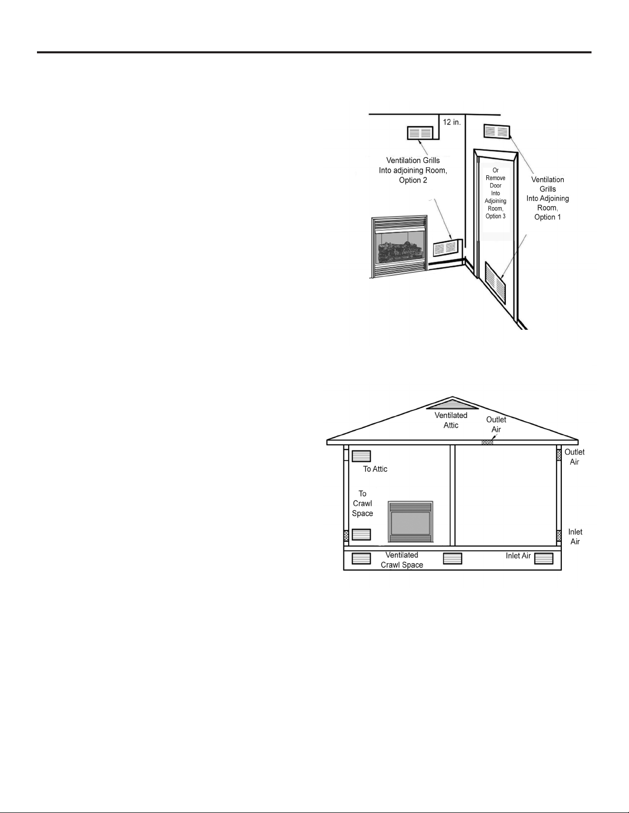
Ventilation Air From Inside Building
This fresh air would come from adjoining
unconned space. When ventilating to an
adjoining unconned space, you must
provide two permanent openings: one
within 12 in. of the wall connecting
the two spaces (see options 1 and 2,
Fig. 4). You can also remove door into
adjoining room (see option 3, Fig. 4).
Follow the National Fuel Gas Code
NFPA 54/ANS Z223.1. Air for Combustion
and Ventilation for required size of
ventilation grills or ducts.
Ventilation Air From Outdoors
Provide extra fresh air by using ventilation
grills or duct. You must provide two
permanent openings: one within 12 in. of
the ceiling and one within 12 in. of the oor.
Connect these items directly to the outdoors
or spaces open to the outdoors. These
spaces include attics and crawl spaces.
Follow the National Fuel Gas Code NFPA
54/ANS Z223.1. Air for Combustion and
Ventilation for required size of ventilation
grills or ducts.
IMPORTANT: Do not provide openings for
inlet or outlet air into attic if attic has a
thermostat-controlled power vent. Heated
air entering the attic will activate the power
vent. Rework worksheet, adding the space
of the adjoining unconned space. The
combined spaces must have enough fresh
air to supply all appliances in both spaces.
Fig. 4 - Ventilation Air from
Inside Building
Fig. 5 - Ventilation Air from Outdoors
11
INSTALLATION
NOTICE: This heater is intended for use as supplemental heat. Use this heater along with your
primary heating system. Do not install this heater as your primary heat source. If you have a
central heating system, you may run system’s circulating blower while using heater. This will
help circulate the heat throughout the house.
WARNING: A qualied technician must install heater. Follow all local codes.
WARNING: Never install the heater:
• in a bedroom or bathroom
• in a recreational vehicle
• where curtains, furniture, clothing, or other ammable objects are less than 42 in. from the
front, top or sides of the heater.
• in high trafc areas
• in windy or drafty areas
WARNING: Maintain the minimum clearances. If possible, provide greater clearances from the
oor, ceiling, and adjoining wall than required (shown in gure 6).
CAUTION: This heater creates warm air currents. These currents move heat to wall surfaces next
to heater. Installing heater next to vinyl or cloth wall coverings or operating heater where impurities
(such as tobacco smoke, aromatic candles, cleaning uids, oil or kerosene lamps, etc.) in the air
exist, may cause walls to discolor.
IMPORTANT: Vent-free heaters add moisture to the air. Although this is benecial, installing heater in
rooms without enough ventilation air may cause mildew to form from too much moisture. See Air for
Combustion and Ventilation, pages 9 through 11.
CHECK GAS TYPE
Be sure your gas supply is right for your heater.
CLEARANCES TO COMBUSTIBLES
Carefully follow the instructions below. This heater is a designed to sit directly on the mantel base.
IMPORTANT: Maintain the minimum clearances shown in Figure 6 on page 12. If you can, provide
greater clearances from oor, ceiling and joining wall.
UNPACKING
1. Remove replace cabinet and hood from carton. Log is wrapped and inside replace.
Do not remove at this time.
2. Remove all protective packaging applied to replace for shipment.
3. Make sure your replace includes one hardware packet.
4. Check replace for any shipping damage. If replace is damaged, call GHP Group, Inc., at 1-877-
447-4768. Please do not return it to the store.
Tools Required:
• Phillips screwdriver • scissors
12
FIREPLACE CLEARANCES
CAUTION: If you install the replace in a home garage
• replace pilot and burner must be at least 18" above oor.
• locate replace where moving vehicle will not hit it.
For convenience and efciency, install replace
• where there is easy access for operation, inspection and service
• in coldest part of room
• If this appliance is to be installed directly on carpeting, tile or other combsutible material, other than
wood ooring, the appliance must be installed on a metal or wood panel extending the full width and
depth of the appliance.
An optional blower kit is available from your retailer. See Accessories, page 38. If planning to use
blower, follow instructions provided with blower for power source.
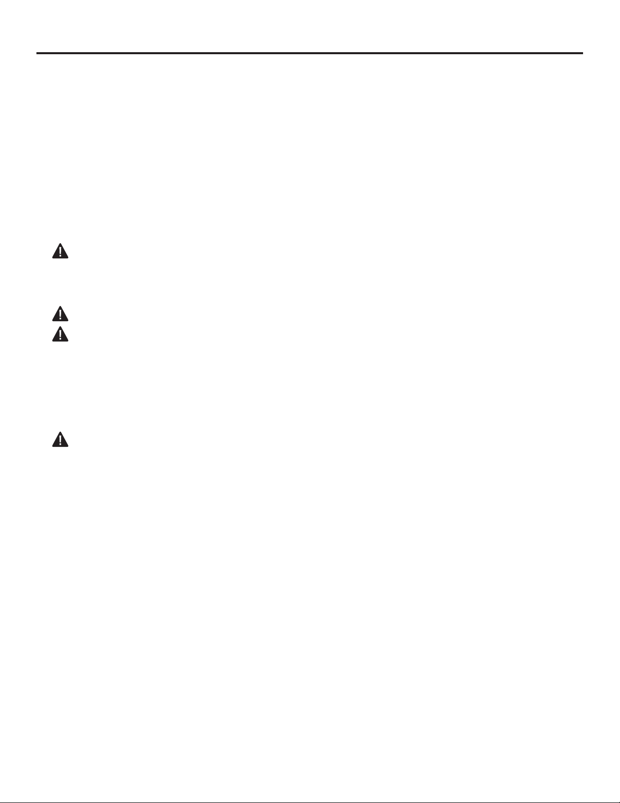
Minimum Clearances For Side Combustible Material, Side Wall and Ceiling
A. Clearances from the side of the replace cabinet to any combustible material and wall should
follow diagram in Figure 6.
B. Clearances from the top of the replace opening to the ceiling should not be less than 36".
Fig. 6 - Minimum Clearance to
Combustible Material
Min.
36''
36''
12''
Either
Side
12''
INSTALLATION
13
INSTALLATION
BUILT IN FIREBOX ENCLOSURE
WARNING: Do not allow any
combustible materials to overlap the
rebox front.
WARNING: Do not allow
combustible or noncombustible
materials to cover any necessary
openings like louvered slots.
WARNING: Never modify or cover
the louvered slots on the front of the
rebox.
This replace insert must be installed into
a framed-in enclosure in order to make
the front ush with the wall.
See Figure 7 if you are installing the
mantel above the replace for the
required clearances.
NOTICE: Surface temperatures of
adjacent walls and mantels become hot
during operation. Walls and mantels
above the replace may become hot
to the touch. If installed properly, these
temperatures meet the requirement of
the national product standard. Follow
all minimum clearances shown in this
manual (see Figure 8).
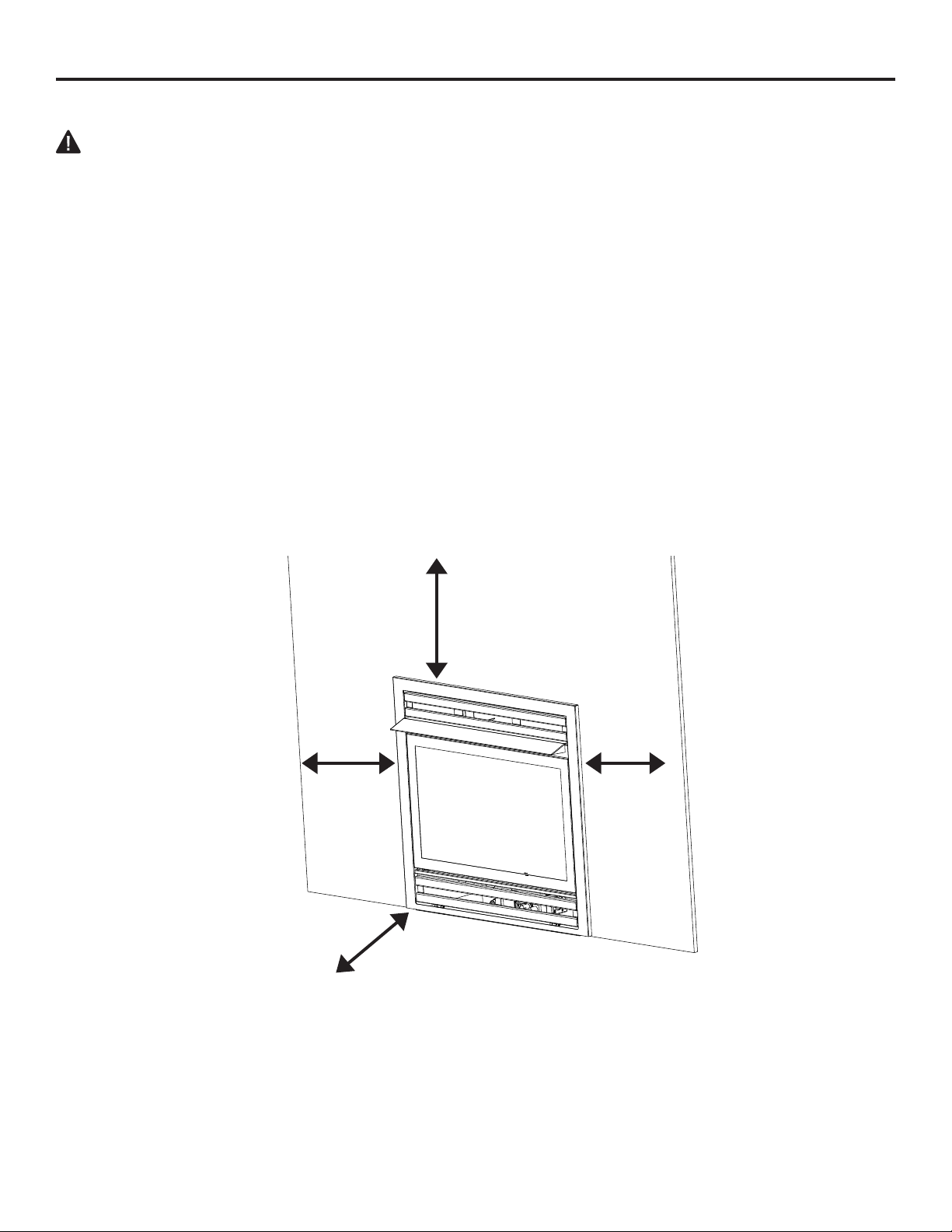
1. Frame in rough opening. Use
dimensions shown in Figure 9 for the
rough opening. If installing in a corner,
use dimensions shown in Figure 10 (page
13 ) for the rough opening. The height
is 26 1/2", which is the same as the wall
opening above.
2. Carefully set replace in front of rough
opening with back of replace inside wall
opening
3. Attach gas line to replace gas
regulator. See Connecting to Gas Supply.
page #.
4. Check all gas connections for leaks.
See Checking Gas Connections, page 24.
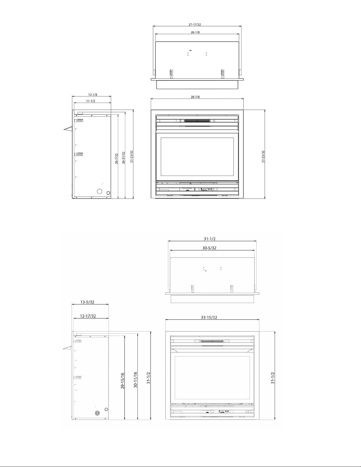
Figure 8 - Rough Opening for Wall
Installation
W
H
D
Figure 7 - Fireplace Clearances
Firebox Size W D H
28" 27 5/8" 14" 27"
32" 31 5/8" 15 1/2" 30 3/4"
Wall Stud
Drywall Board
23"
21"
19"
16"
13"
12”
10”
8”
2.5”
3/4" Maintain Clearance
9/16”
6”
Fig. - Mantle Clearances (Top)
Wall Stud
Drywall Board
23"
21"
19"
16"
13"
12”
10”
8”
2.5”
3/4" Maintain Clearance
9/16”
6”
Fig. - Mantle Clearances (Top)
14
IMPORTANT: When nishing your rebox, combustible materials such as wall board, gypsum board,
sheet rock, drywall, plywood, etc, must have 1/2" clearance to the sides and top of the rebox.
Combustible materials should never overlap the rebox front.
INSTALLATION
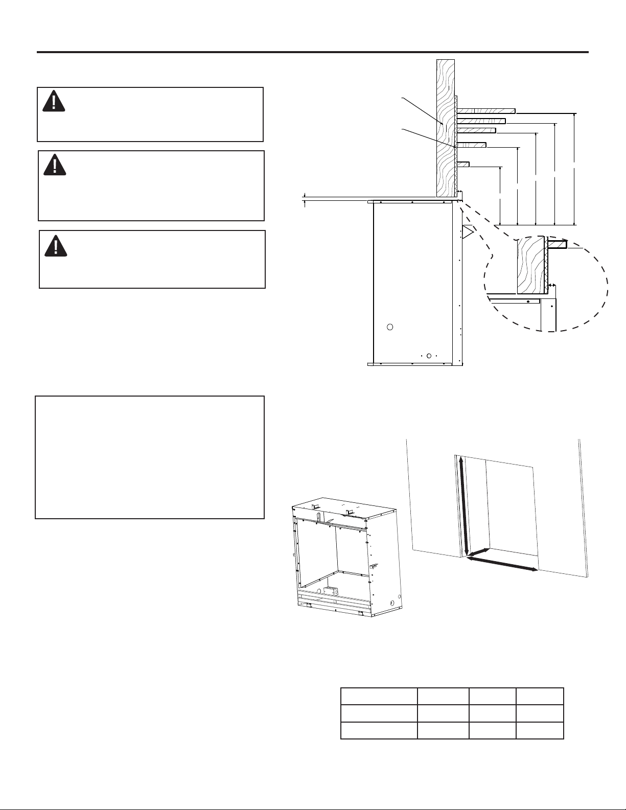
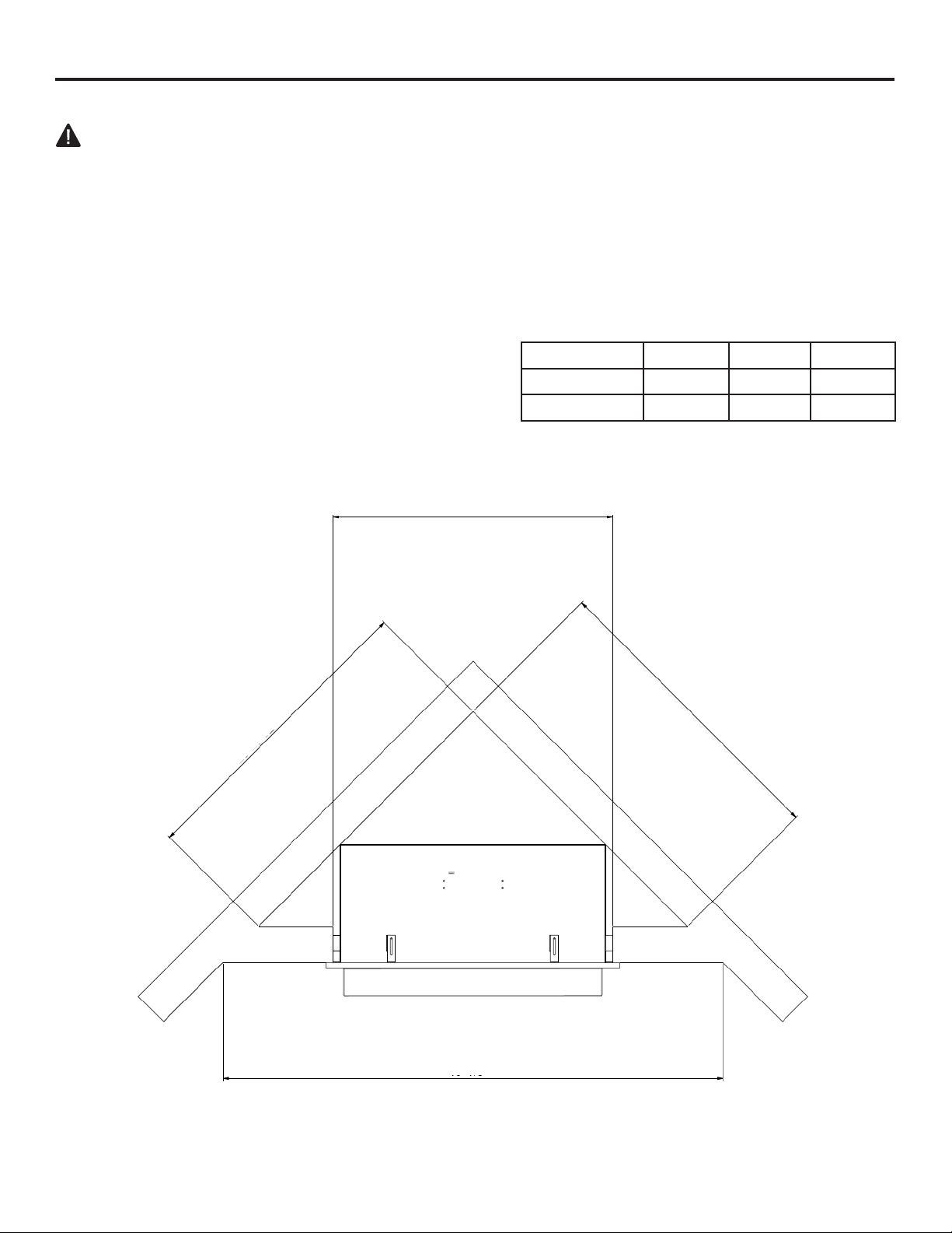
BUILT IN FIREBOX INSTALLATION
WARNING: This optional blower is equipped with a three-prong (grounding) plug for your
protection against shock hazard and must be plugged directly into a properly grounded three-prong
receptacle.
Firebox must be disconnected from gas supply and removed from mantel before installing fan
accessory. Contact a qualied service person to do this.
Firebox Size A B W
Intermediate 49 1/8" 25 3/4" 27 9/16"
Full 55 3/16" 34 1/16" 31 1/2"
A
B
B
w
Fig. 9 - Corner Installation Dimensions
15
INSTALLATION
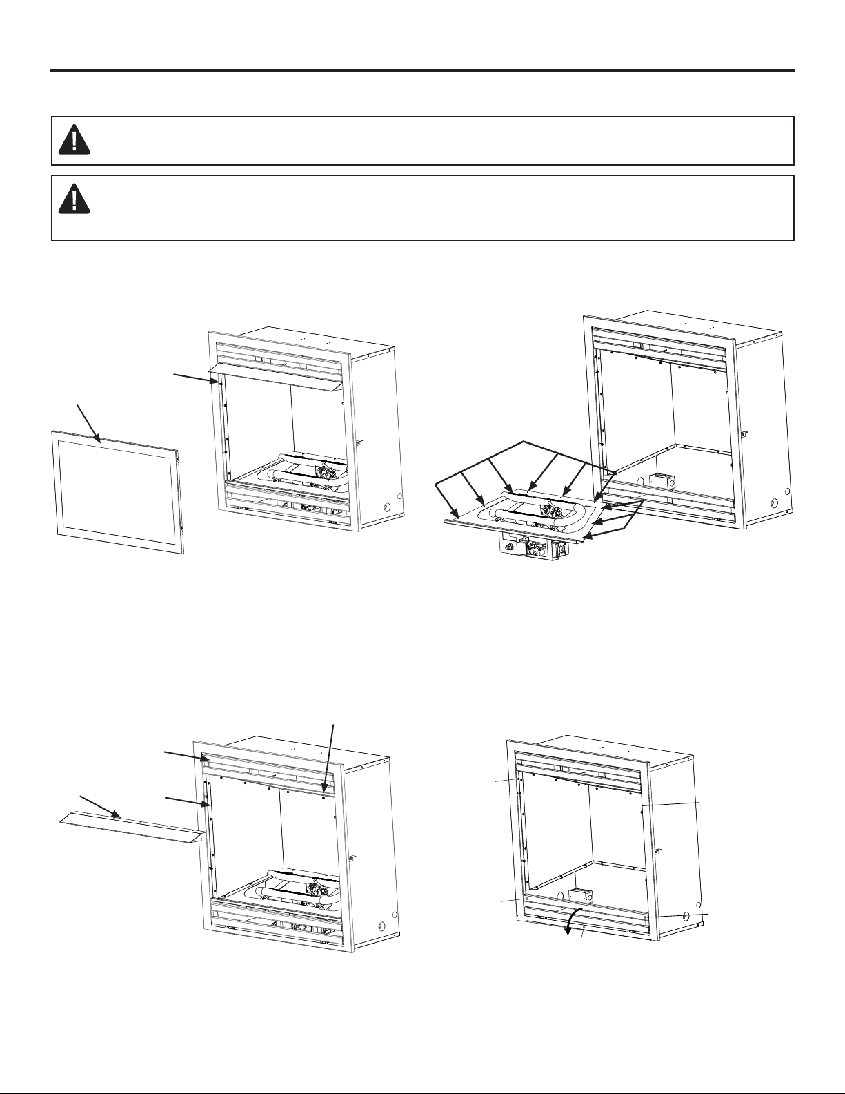
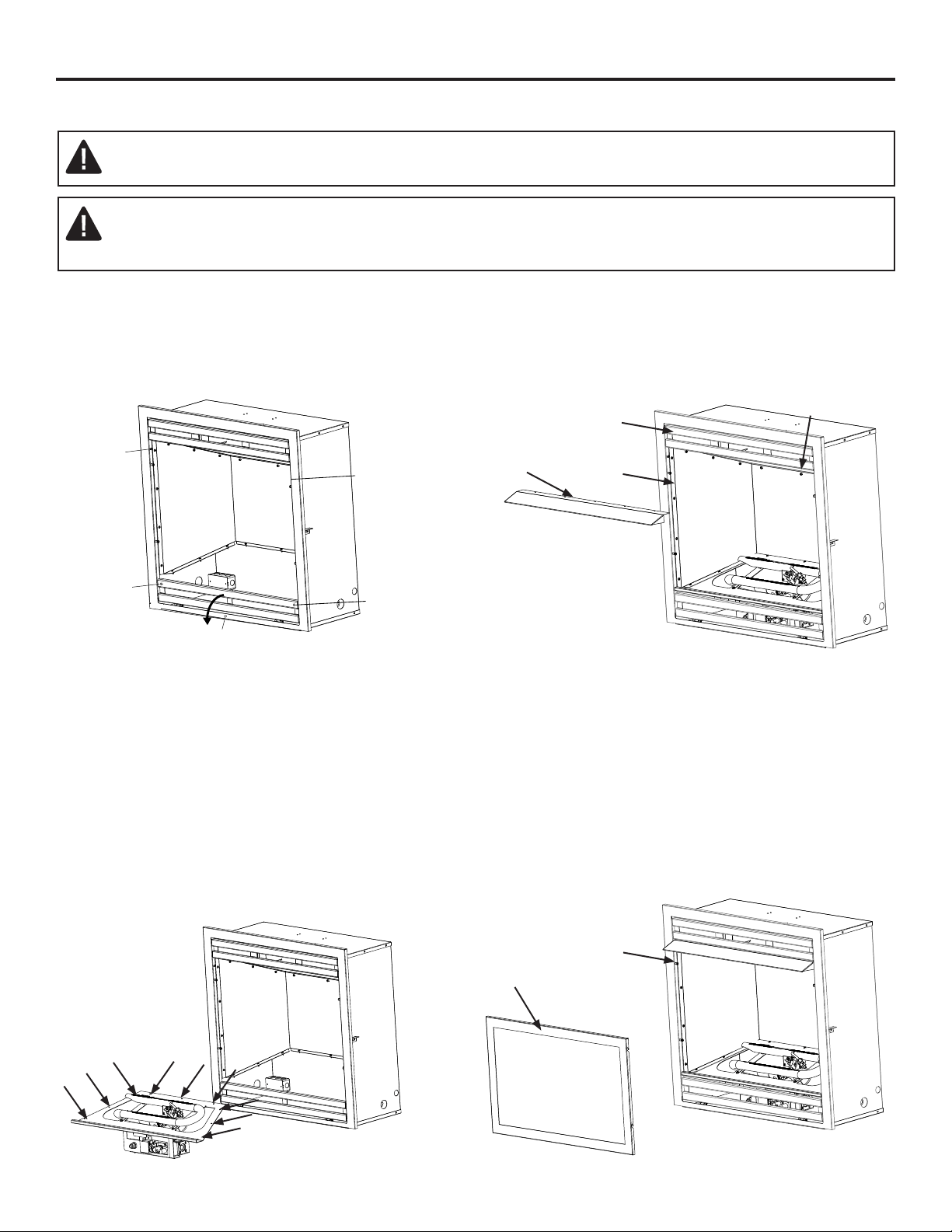
WARNING: Always have screen in place before operating rebox insert. This prevents
excessive temperatures on replace surfaces.
WARNING: Failure to position the parts in accordance with these diagrams or failure to
use only parts specically approved with this replace may result in property damage
or personal injury.
1. Remove the screen
4. Remove the frame by unscrewing top two
screws, open the bottom grill and unscrew
two bottom screws and center nut.
Screen
Shoulder
Screw
Louver
Hood
Firebox
Top
Sheet Metal
Screws
2. Remove the hood by unscrewing
all 5 screws. (Only 4 screw for the
Intermediate size)
3. Remove burner by unscrewing all 9 screws
DISASSEMBLY
Screws
Screws
Top
Screw
Bottom Screw
(Behind bottom grat
e)
Top
Screw
Nut
(Behind bottom grate)
Bottom Screw
(Behind bottom grate)
16
INSTALLATION
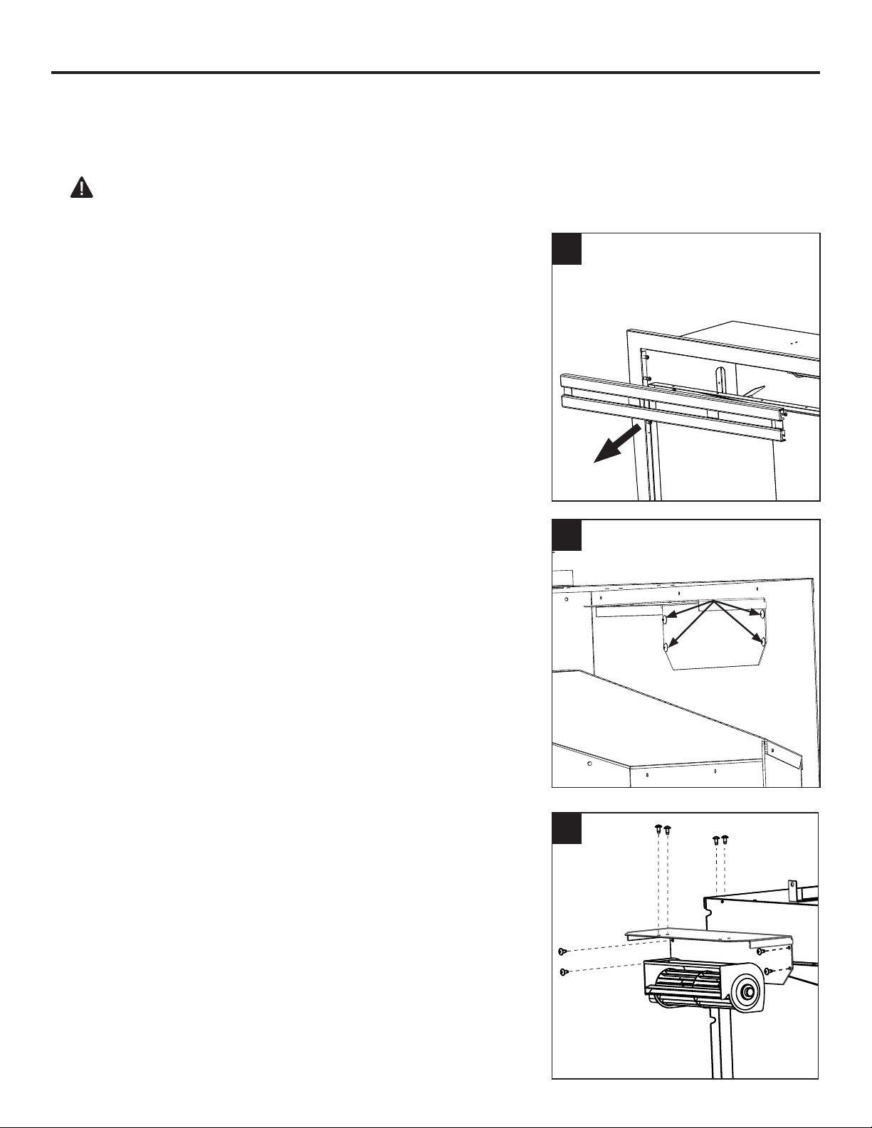
1. Remove top grill (if frame is not already removed).
XSEC0004-XSEC0004SECTION
2
3. Assemble Fan and the removed bracket together by
screwing x4 screws into the top of the bracket.
CAUTION: Label all wires prior to disconnection when servicing controls. Wiring errors can
cause improper and dangerous operation.
Verify proper operation after servicing.
NOTE: If any of the original wire as supplied with the appliance must be replaced, it must be
replaced with a wire of at least an equal temperature rating.
BLOWER INSTALLATION (OPTIONAL)
2. Remove bracket from top vent by unscrewing x4 screws
XSEC0004-XSEC0004SECTION
3
NOTE: Installation may require two people.
1
Screws
17
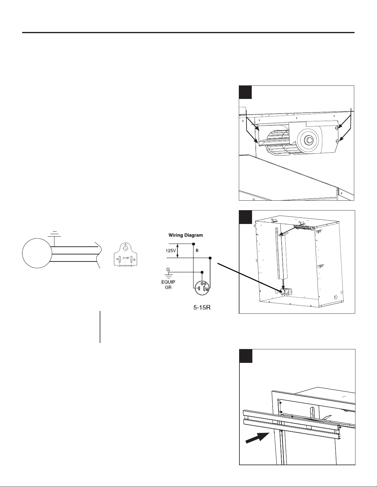
5
4. Reinsert fan and bracket assembly into the Top Vent
and screw in x 4 screws into the back of the replace
cabinet.
XSEC0004-XSEC0004SECTION
BLOWER MOUNTING LOCATION
4
Screws
Screws
5. Route the fan cable through the race way.
Note: Junction box needs an outlet installed.
6
6. Reassemble top grill (if frame is not already
removed).
INSTALLATION
BLOWER
SOPLADOR
BLACK/NEGRO
WHITE/BLANCO
GREEN/VERDE
BLOWER WIRING DIAGRAM
Install a NEMA 5-15R
receptacle for power supply
IF ANY ORIGINAL WIRING SUPPLIED
WITH THIS HEATER MUST BE
REPLACED, IT MUST BE TYP AWG
105C WIRE OR ITS EQUIVALENT
EXCEPT AS INDICATED.
SI VOUS DEVEZZ FAIRE REMPLACER
LES FILS D’ORIGINE DU RADIATEUR,
PROCUREZ-VOUS DU FIL AWG 105C
OU L’EQUIVELENT SAUF INDICATION
CONTRAIRE.
18
CONNECTING TO GAS SUPPLY
WARNING: A qualied service technician must connect heater to gas supply. Follow all local
codes.
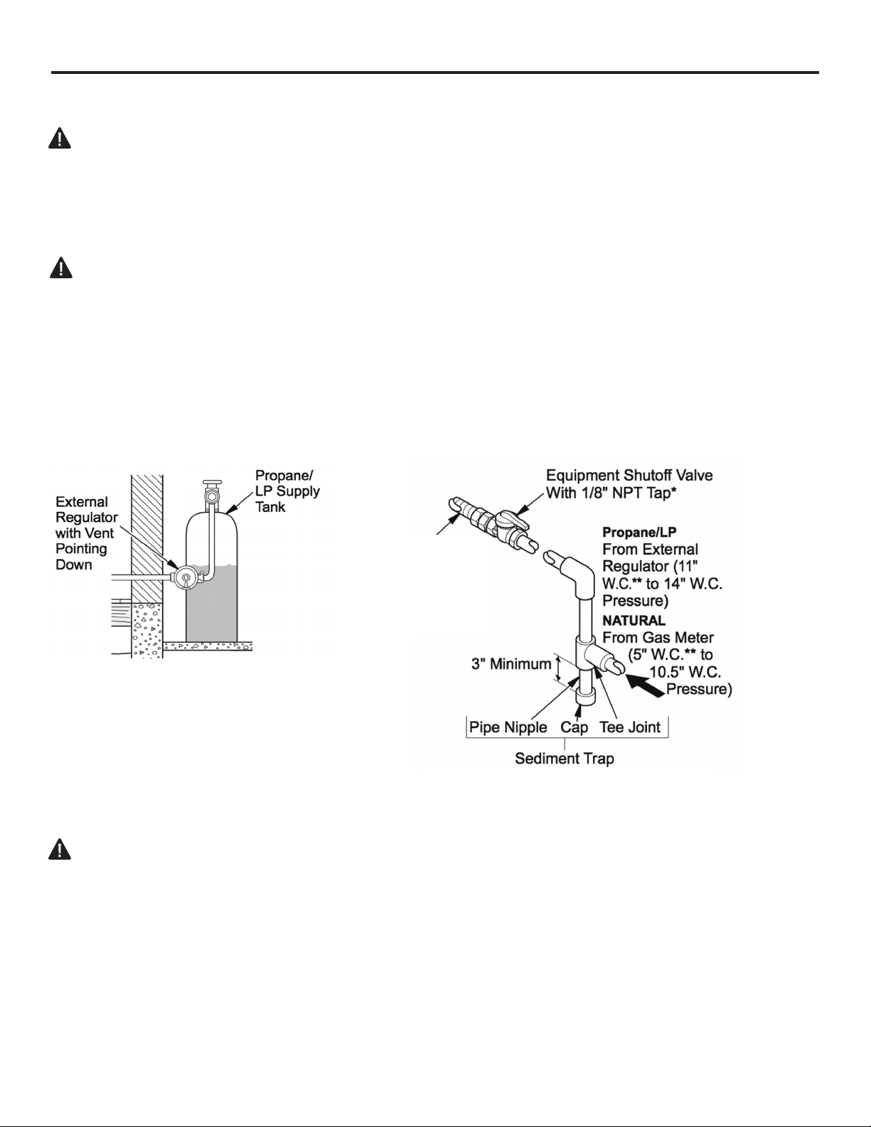
CAUTION: Never connect heater directly to the gas supply. This heater requires an external
regulator (not supplied). The external regulator between the gas supply and heater must be installed.
Gas supplier provides external regulator for natural gas.
WARNING: Never connect heater to private (non-utility) gas wells. This gas is commonly known
as wellhead gas.
The installer must supply an external regulator for liquid propane. The external regulator is
provided by the gas supplier for natural gas. The external regulator will reduce incoming gas pres-
sure. You must reduce incoming gas pressure to between 11 and 14 in. of water column for propane
and between 5 and 10.5 in. of water column for natural gas. If you do not reduce incoming gas pres-
sure, heater regulator damage could occur. Install external regulator with the vent pointing down as
shown in Fig. 6. Pointing the vent down protects it from freezing rain or sleet.
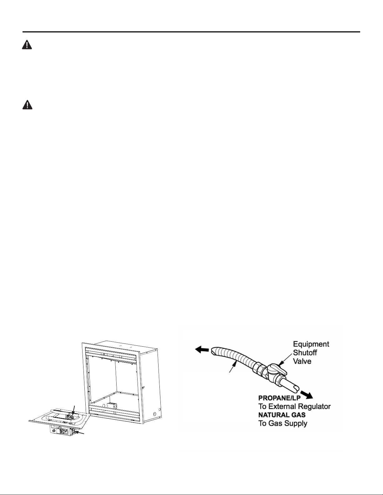
* Purchase the optional equipment shutoff valve from your local Home Center store.
INSTALLATION
CAUTION: Use only new black iron or steel pipe. Internally tinned copper tubing
may be used in certain areas. Check your local codes. Use pipe of ½ in. diameter
or greater to allow proper volume gas to heater. If pipe is too small, loss of pressure
will occur. Installation must include an equipment shutoff valve, union, and plugged
1/8-in. NPT tap. Locate NPT tap within reach for test gauge hook up. NPT tap must
be upstream from heater (See Fig. 10).
IMPORTANT: Install equipment shutoff valve in an accessible location. The equipment
shutoff valve is for turning on or shutting off the gas to the appliance. Apply pipe joint
sealant lightly to male threads. This will prevent excess sealant from going into pipe.
Excess sealant in pipe could result in clogged heater valves.
Approved
Flexible
Gas Line
or 1/2''
Black Pipe
Fig. 9 - Regulator Conversion
Fig. 10 - Gas Connection
19
INSTALLATION
Installation Items Needed (Not Provided)
Fig. 11 - Attaching Flexible Gas Line
to Equipment Shutoff Valve
Flexible Gas Line
or Black Pipe to
Fireplace Cabinet
Regulator
To Regulator
• 8'' Adjustable Wrench
• 8'' Pipe Wrench
• Flexible Gas Line (24'' Min.) or 1/2'' Black Pipe
• 90 Deg. 3/8 NPT x 3/8'' Flare Fitting or 3/8'' Street Elbow
• Sealant (Resistant to Propane (LP) Gas)
• Shut Off Valve
1) A variety of options are possible for routing the Gas Connection Lines depending on where
your Gas Supply line is located. Install the 3/8'' Fitting to the Fireplace Cabinet Regulator
using Sealant and direct the attachment and either left or right toward the Gas Supply Line.
2) Install the Gas Line to the 90 Deg. tting and attach to the Shut Off Valve. It may be
necessary to cut and access hole in the side or bottom of the Cabinet depending on
your particular connection.
3) Check all connections for gas leaks.
NOTICE: Most building codes do not permit concealed gas connections. Check
your local building code prior to using a Flexible Gas Line for this installation.
CAUTION: Use pipe joint sealant that is resistant to gas (PROPANE or NG). We
recommend that you install a sediment trap in a supply line as shown in Fig. 10.
Locate sediment trap where it is within reach for cleaning and not likely to freeze.
Install in the piping system between fuel supply and heater. A sediment trap traps
moisture and contaminants. This keeps them from going into heater controls. If
sediment trap is not installed or is installed incorrectly, heater may not run properly.
CAUTION: Avoid damage to regulator. Hold gas regulator with wrench when
connecting into gas piping and/or ttings. NG Models: 5 in. to 10.5 in. W.C. Gas
supplier provides external regulator for natural gas.
Pilot
Regulator
20
INSTALLATION
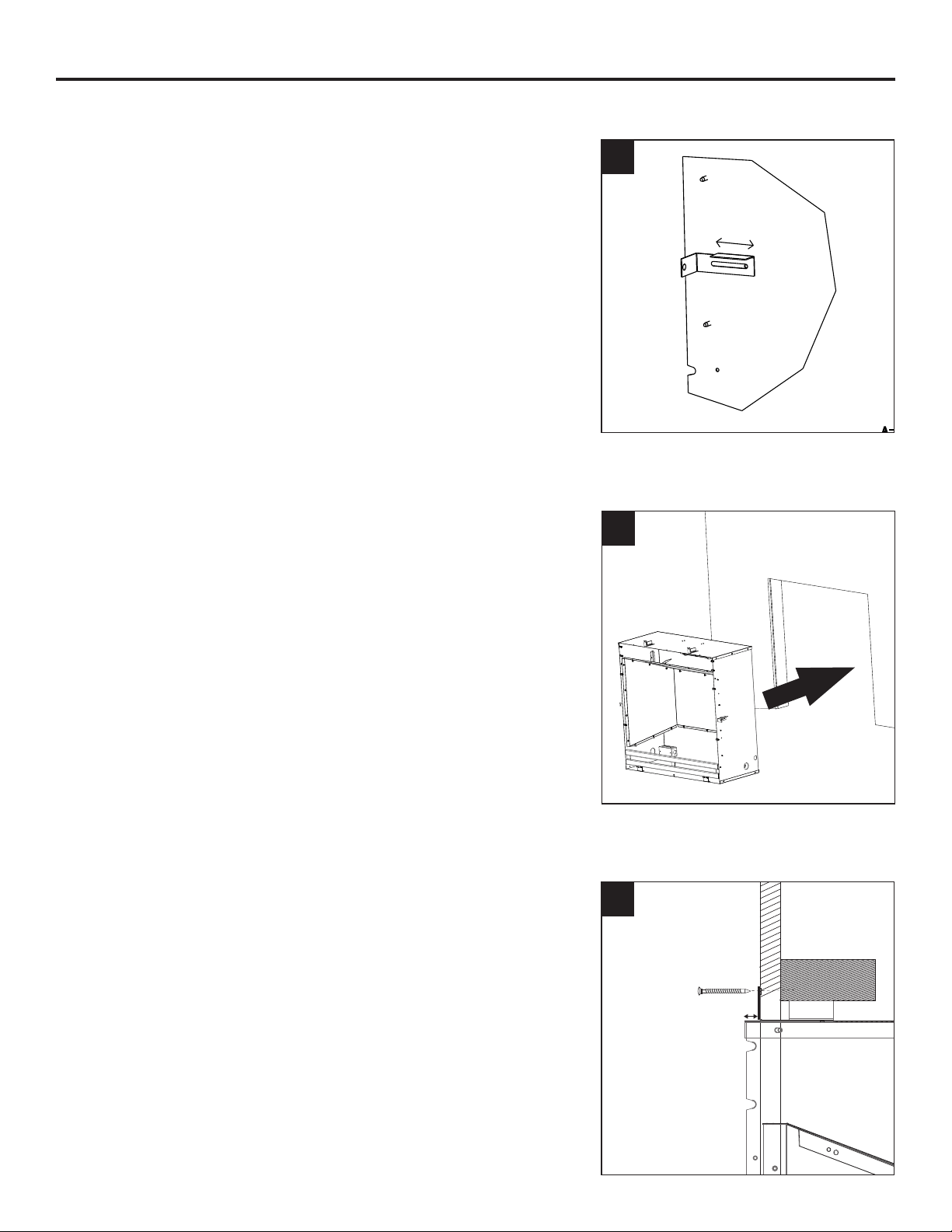
3. Screw all 6 standoffs into the studs of the wall.
WALL INSTALLATION
1. Adjust the standoffs to the wall thickness.
2. Carefully lift the insert through the center
opening in the front of the wall. Slide the insert
back through the opening until the metal trim
makes contact with the front of the wall.
1
2
THE FINAL DIMENSION OF THE FIREPLACE INSTALLATION
THE DISTANCE BETWEEN DRYWALL AND THE EDGE OF
FIRE PLACE CHAMBER IS AT LEAST 0.57 INCH
XSEC0001-XSEC0001SECTION
9/16”
3
21
INSTALLATION
WARNING: Always have screen in place before operating rebox insert. This prevents
excessive temperatures on replace surfaces.
WARNING: Failure to position the parts in accordance with these diagrams or failure to
use only parts specically approved with this replace may result in property damage
or personal injury.
5. Replace the screen
Screen
Shoulder
Screw
Louver
Hood
Firebox
Top
Sheet Metal
Screws
3. Replace the hood and tighten the 5
screws holding it in place. (Only 4 screw for
Intermediate size)
2. Replace burner and tighten all 9 screws
1. Install the frame by screwing in top two
screws, open the bottom grill and screw in two
bottom screws and center nut.
REASSEMBLY
4. Assemble Logs (see next page)
Top
Screw
Bottom Screw
(Behind bottom grate)
Top
Screw
Nut
(Behind bottom grate)
Bottom Screw
(Behind bottom grate)
22
PHZCI28LP
PHZCI28NG
WARNING: Failure to position the parts in accordance with these diagrams or failure to use only parts
specically approved with this heater may result in property damage or personal injury.
CAUTION: After installation and peridically thereafter, check to ensure that no yellow ame comes in
contact with any log. With the heater set to High, check to see if yellow ames contact any log. If so,
reposition logs according to the log installation instructions in this manual. Yellow ames contacting
logs will create soot.
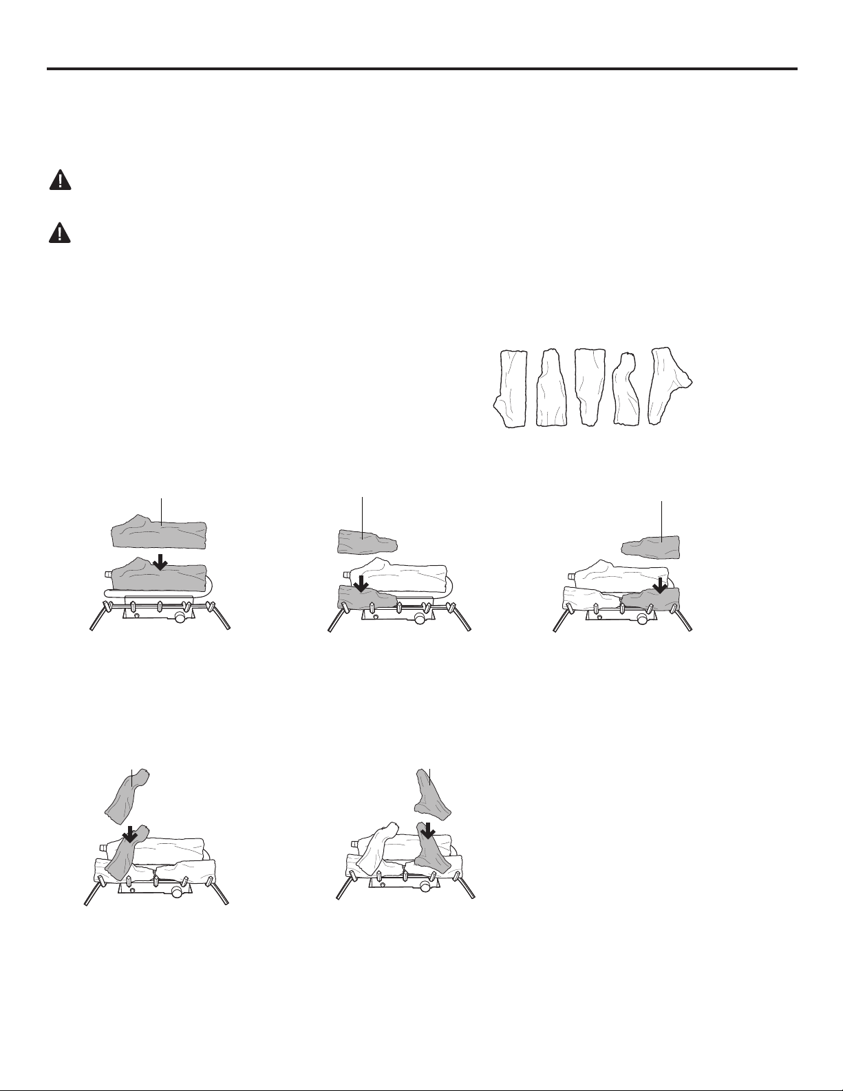
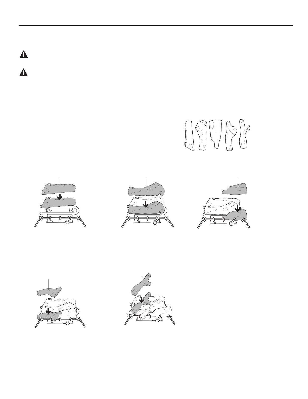
It is very important to install the logs
exactly as instructed. Do not modify logs.
Use only logs supplied with heater.
Each log is marked with a number.
this number will help you identify the logs
when installing.
Provided Logs: 5
Installing Log #1 Installing Log #2 Installing Log #3
2
1
3
1. Insert log #1 onto the
rear row of pins on the
base pan.
2. Insert log #2 onto the
front left pin on the base
pan.
3. Insert log #3 onto the
front right pin on the base
pan.
Installing Log #4 Installing Log #5
4
5
4. Insert log #4 onto the left
pin of log #1 and the pin of
log #2.
5. Insert log #5 onto the
right pin of log #1 and the
pin of log #3.
1
2 3 4 5
ASSEMBLING LOGS
INSTALLATION
23
PHZCI32LP
PHZCI32NG
WARNING: Failure to position the parts in accordance with these diagrams or failure to use only parts
specically approved with this heater may result in property damage or personal injury.
CAUTION: After installation and peridically thereafter, check to ensure that no yellow ame comes in
contact with any log. With the heater set to High, check to see if yellow ames contact any log. If so,
reposition logs according to the log installation instructions in this manual. Yellow ames contacting
logs will create soot.
It is very important to install the logs
exactly as instructed. Do not modify logs.
Use only logs supplied with heater.
Each log is marked with a number.
this number will hep you identify the logs
when installing. After installing logs, add
decorative cinders around the grate base,
do not place any decorative cinders on
logs or burner.
Provided Logs: 5
Installing Log #1 Installing Log #2 Installing Log #3
2
1
4
1. Insert log #1 onto the
rear brackets of the base
pan.
2. Insert log #2 onto the
middle row of pins on the
base pan.
4 . Insert log #4 onto the
front left pin of the base
pan.
Installing Log #4 Installing Log #5
3
5
3. Insert log #3 onto the
front right pin of the base
pan.
5. Insert log #5 onto the
left pins of log #1 & #2 and
the pin of log #3.
ASSEMBLING LOGS
4
3
5
41 2 3
INSTALLATION
24
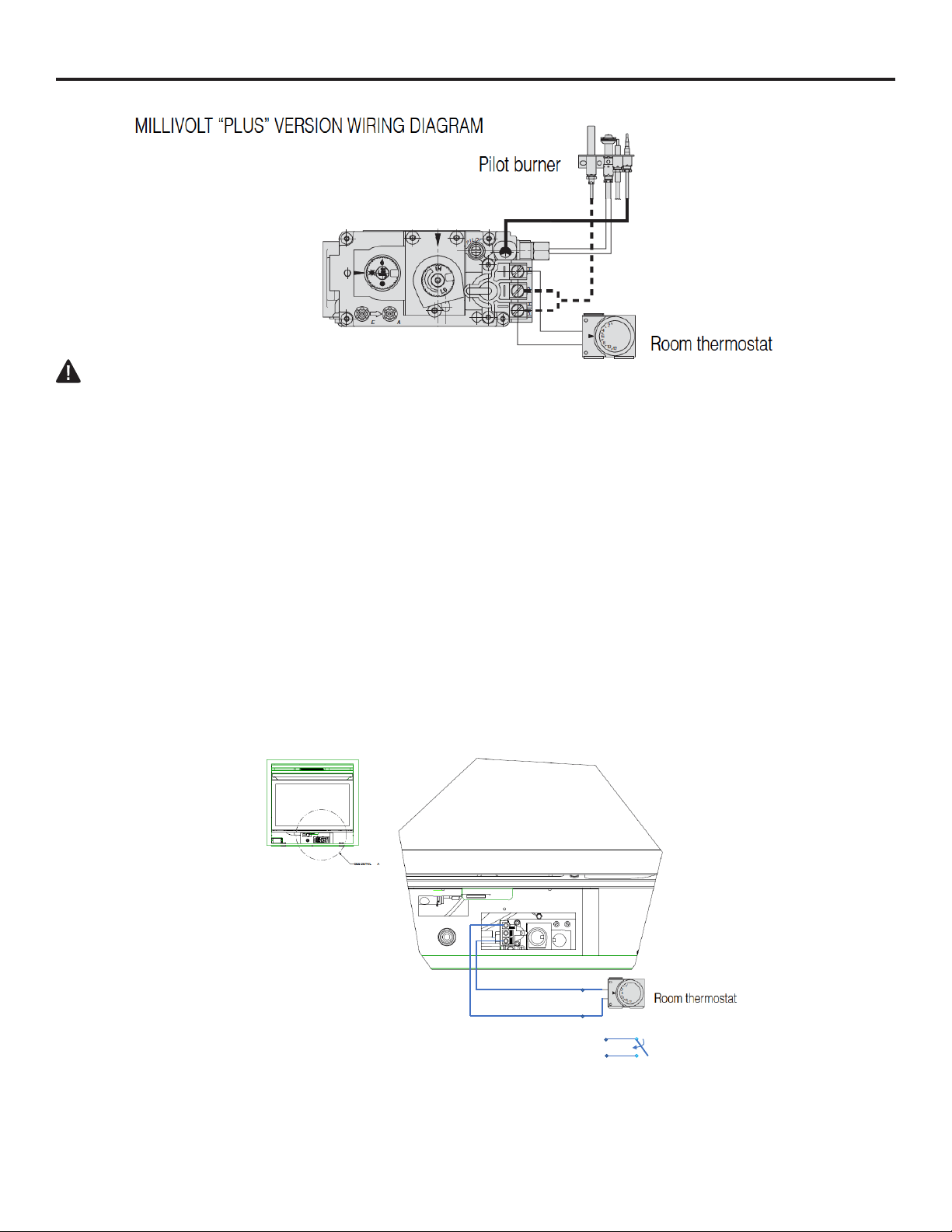
WIRING DIAGRAM
WARNING:
Never connect valve to line voltage.
Failure to follow this will result in damage to equipment and could result in severe injury or death.
WIRING INSTRUCTIONS:
Follow the wiring instructions furnished by the appliance manufacturer, if available, or use the
following general instructions. Appliance manufacturers instructions always supercede these
instructions.
All wiring must comply with applicable electrical codes and ordinances.
Disconnect the appliance power source before making any electrical connections to prevent the
possibility of electrical shock or damage to equipment.
1. Check the millivolt rating on the gas valve and make sure it matches the available supply. Install
thermostat and other accessories as required.
2. For the Millivolt Plus, connect thermocouple to convenient upper or lower connection port. Hand
tighten, and then rotate 1/4 turn with wrench.
3. Connect the Thermo-generator leads to TPTH and TP terminals on main operator coil.
4. This valve may only be used in self-generating systems. Use only components specically
designed for use in a millivolt system.
INSTALLATION
Wall Switch
Option 1
Option 2
We Recommend
24 AWG, stranded wire with 2 conductors and PFA insulation
We give no detail on what type of wire to use to hook up tstats or switches, no detail what type of wall
switch to use or how to wire it.
25
CHECKING GAS CONNECTIONS
WARNING: Test all gas piping and connections for leaks after installing or servicing. Correct all
leaks immediately.
WARNING: Never use an open ame to check for a leak. Apply a mixture of liquid soap and water
to all joints. If bubbles form, there may be a leak. Correct all leaks immediately.
Pressure Testing Gas Supply Piping System
Test Pressures In Excess Of 1/2 PSIG ( 3.5kPa )
1. Disconnect heater with its appliance main gas valve (control valve) and equipment shutoff valve
from gas supply piping system. Pressures in excess of 1/2 PSIG will damage heater regulator.
2. Cap off open end of gas pipe where equipment shutoff valve was connected.
3. Pressurize supply piping system by either using compressed air or opening gas supply tank valve.
4. Check all joints of gas supply piping system. Apply mixture of liquid soap and water to gas joints. If
bubbles form, there may be a leak.
5. Correct all leaks immediately.
6. Reconnect heater and equipment shutoff valve to gas supply. Check reconnected ttings for leaks.
Test Pressures Equal To or Less Than 1/2 PSIG (3.5 kPa)
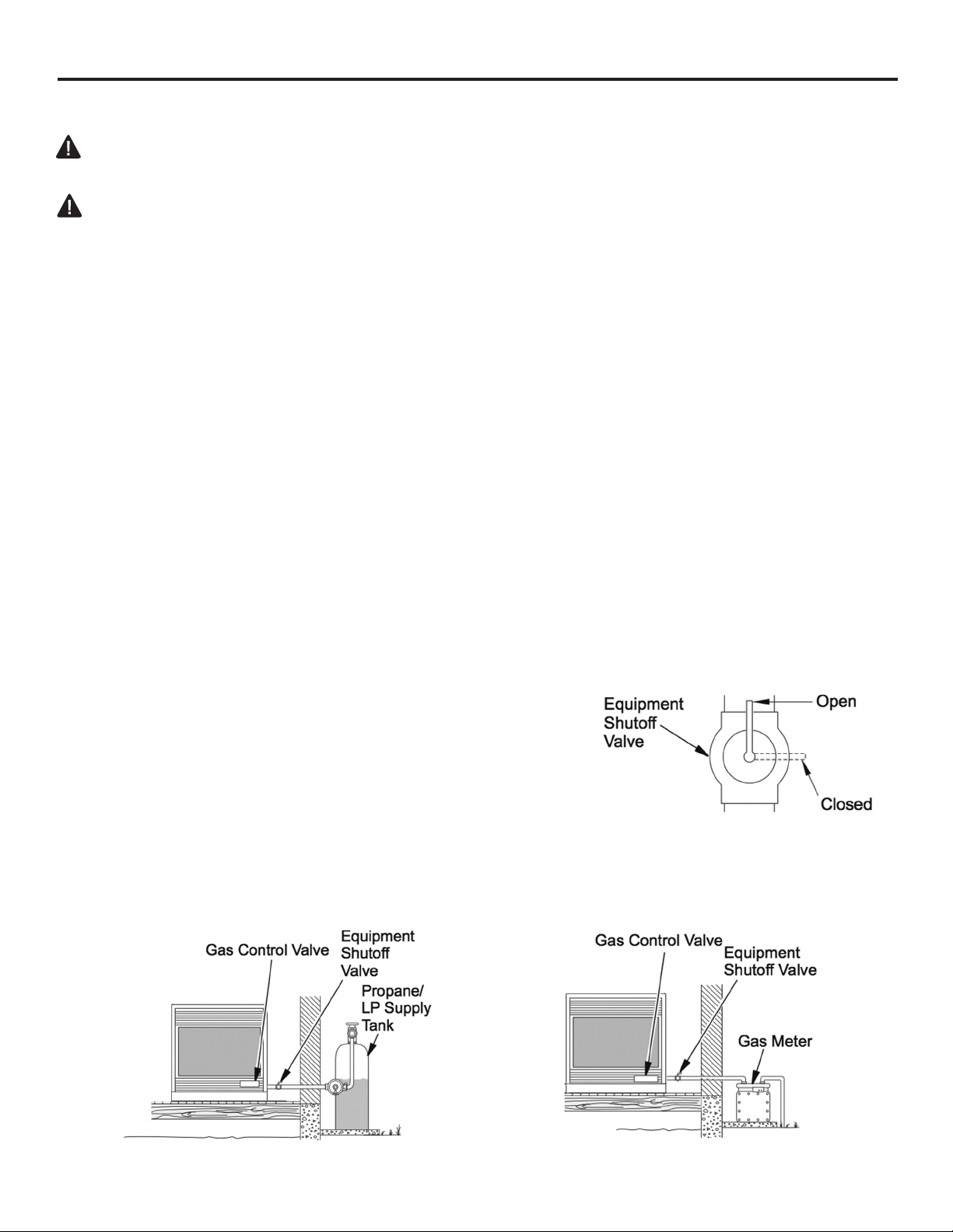
1. Close equipment shutoff valve (See Fig. 12).
2. Pressure supply piping system by either using compressed air or opening gas supply tank valve.
3. Check all joints from gas meter to equipment shutoff valve (See Fig.13). Apply mixture of liquid
soap and water to gas joints. If bubbles form, there may be a leak.
4. Correct all leaks immediately.
Pressure Testing Heater Gas Connections
1. Open equipment shutoff valve (See Fig. 12).
2. Open gas supply tank valve.
3. Make sure control knob of heater is in the OFF position.
4. Check all joints from equipment shutoff valve to control valve
(See Fig. 13). Apply mixture of liquid soap and water to gas joints.
If bubbles form, there may be a leak.
5. Light heater (see Operation, page 23).
Check all other internal joints for leaks.
6. Turn off heater (see "To Turn Off Gas to Appliance," page 24).
INSTALLATION
Fig. 13 - Checking Gas Joints
(Propane/LP Only)
Fig. 12 - Equipment Shutoff Valve
Fig. 14 - Checking Gas Joints
(Natural Gas Only)
26
OPERATION
FOR YOUR SAFETY
READ BEFORE LIGHTING
WARNING: If you do not follow these instructions exactly, a re or explosion may result
causing property damage, personal injury or loss of life.
A. This appliance has a pilot which must be lighted by the electronic ignitor. When lighting the pilot,
follow these instructions exactly.
B. BEFORE LIGHTING smell all around the appliance area for gas. Be sure to smell next to the oor
because some gas is heavier than air and will settle on the oor.
WHAT TO DO IF YOU SMELL GAS
• Do not try to light any appliance.
• Do not touch any electrical switch; do not use any phone in your building.
• Immediately call your gas supplier from a neighbor’s phone. Follow the gas supplier’s instructions.
• If you cannot reach your gas supplier, call the re department
C. Use only your hand to push in or turn the gas control knob. Never use tools. If the knob will not
push in or turn by hand, don’t try to repair it, call a qualied service technician. Forced or attempted
repair may result in re or explosion.
D. Do not use this appliance if any part has been under water. Immediately call a qualied service
technician to inspect the appliance and to replace any part of the control system and any gas control
which has been under water.
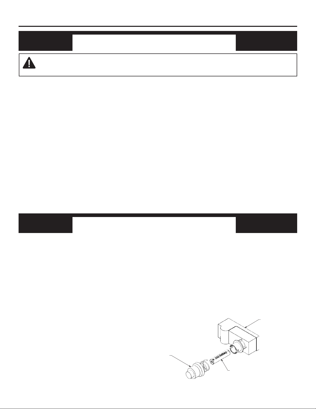
BATTERY INSTRUCTIONS
• Batteries are included.
• Remove batteries when depleted.
• Install/replace the batteries according to the type and quantity stated in
table below.
• Do not mix old and new batteries. New batteries should be the same
brand for best results.
• Be sure to observe proper polarity (+/-) when installing or replacing the
batteries. Damage due to improper battery installation may void the
warranty on the product.
• For remote control systems, maximize battery life by turning off the re-
ceiver when it is not in use.
• For long periods of non-operation, remove batteries from all compnents
for safety.
Component Type of Battery Battery Qty.
• Ignitor AAA 1
Ignitor Base
Ignitor Cap
AAA Battery
(Positive Side Facing Outward)
27
OPERATION
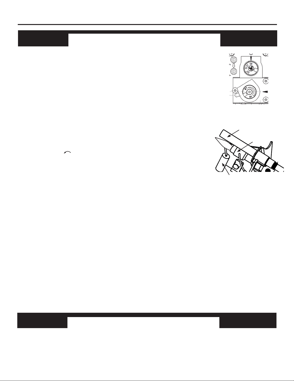
LIGHTING INSTRUCTIONS
Start-up Procedure
1. STOP! Read the safety information to the left on this label.
2. Open the lower access panel located below the replace screen.
3. Set the room thermostat, if present, to the lowest level. Set the wall
switch, if present, to its off position. Press slightly and turn the control
knob clockwise to the "OFF" position (See Fig. 1).
4. Wait ve (5) minutes to clear out any gas. Then smell for gas,
including near the oor. If you smell gas, STOP! Follow “B” in the safety
information to the left on this label. If you don’t smell gas, go to the next
step.
Note: LP gases do not vent upward.
Pilot ame ignition
5. Press slightly and rotate the "OFF / PILOT / ON" control knob
counterclockwise to the "PILOT" position.
6. With control knob depressed, push down on the ignition button until
the pilot lights. The pilot is located behind the replace screen, centered
near the rear of the burner.
Keep the knob fully depressed for at least thirty (30) seconds until air in
the pilot line vents and a strong pilot ame is present. Release the knob
and verify that the pilot ame remains lit. (See Fig. 2)
Millivolt
Generator
Pilot
Fig. 1 - Controls
Ignitor
• Do not attempt to light the pilot by hand.
Igniting the main burner
7. Conrm that the room thermostat or wall switch, if present, is set to its on position. Turn the "HI/LO"
knob to the "LO" setting.
8. Turn the control knob counterclockwise to the "ON" position. The gas path to the main burner is
now open. The maximum gas ow to the burner is obtained with the HI-LO knob fully turned counter-
clockwise ("HI" position). (See Fig. 1)
9. Close lower access panel.
• If the control knob does not pop up when released,stop and immediately call a qualied service
technician or gas supplier.
• If pilot goes out repeat steps 3 through 6. Wait (1) minute before attempting to light pilot again. If
after several tries the pilot still goes out, turn the gas control knob clockwise to the “OFF” position and
call a qualied service technician.
Stand-by position
10. To maintain a ame at the pilot burner with the main burner off, turn the control knob to the
"PILOT" position. (See Fig. 1)
Note: Pilot takes up to 1 min to ignite due to the time it takes the millivolt generator to heat up.
Fig. 2 - Pilot Flame
TO TURN OFF GAS TO APPLIANCE
1. Open the lower access panel located under the replace screen.
2. Turn control knob clockwise to the “OFF” position.
3. Close lower access panel.
Caution After shutting down, wait at least ve minutes before re-igniting. This will allow the safety
interlock to reset.
28
OPERATION
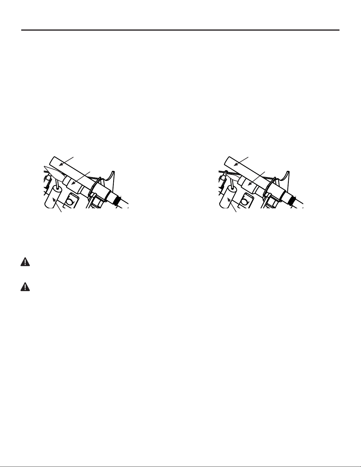
INSPECTING BURNERS
Check pilot ame pattern and burner ame patterns often.
PILOT FLAME PATTERN
Figure 20 shows a correct pilot ame pattern. Figure 21 shows an incorrect pilot ame pattern. The
incorrect pilot ame is not touching the thermocouple. This will cause the thermocouple to cool. When
the thermocouple cools, the replace will shut down.
If pilot ame pattern is incorrect, as shown in Figure 21.
• turn replace off (see To Turn Off Gas to Appliance, page 24.
• see Troubleshooting, page 34.
WARNING: Do not allow fans to blow directly into the replace. Avoid any drafts that alter burner
ame patterns.
WARNING: Do not use a blower insert, heat exchanger insert or other acessory not approved for
use with this heater.
Fig. 20 - Correct Pilot Flame Pattern Fig. 21 - Incorrect Pilot Flame Pattern
Millivolt
Generator
Pilot
Ignitor
Millivolt
Generator
Pilot
Ignitor
29
CARE AND MAINTENANCE
WARNING: Turn off heater and let cool before servicing.
CAUTION: You must keep control areas, burner, and circulating air passageways of heater
clean. Inspect these areas of heater before each use. Have heater inspected yearly by a
qualied service person. Heater may need more frequent cleaning due to excessive lint
from carpeting, bedding material, pet hair, etc.
WARNING: Failure to keep the primary air opening(s) of the burner(s) clean may result in sooting
and property damage.
BURNER ORIFICE HOLDER AND PILOT AIR INLET HOLE
The primary air inlet holes allow the proper amount of air to mix with the gas. This provides a clean
burning ame. Keep these holes clear of dust, dirt, lint and pet hair. Clean these air inlet holes prior to
each heating season. Blocked air holes will create soot. We recommend that you clean the unit every
three months during operation and have replace inspected yearly by a qualied
service person.
We also recommend that you keep the burner tube and pilot assembly clean and free of dust and dirt.
To clean these parts we recommend using compressed air no greater than 30 PSI. Your local
computer store, hardware store or home center may carry compressed air in a can. If using
compressed air in a can, please follow the directions on the can. If you don’t follow directions on the
can, you could damage the pilot assembly.
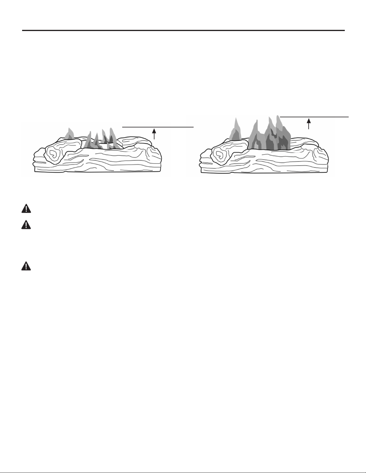
BURNER FLAME PATTERN
Figure 22 shows a correct burner ame pattern. Figure 23 shows an incorrect burner ame pattern.
The incorrect burner ame pattern shows sporadic, irregular ame tipping. The ame should not be
dark or have an orange/reddish tinge.
Note: When using the replace the rst time, the ame will be orange for approximately one hour until
the log cures.
If burner ame pattern is incorrect, as shown in Figure 23
• turn replace off (see To Turn Off Gas to Appliance, page 24).
• see Troubleshooting, page 34.
2-3 inches
above logs
6-12 inches
above logs
Fig. 22 - Correct Burner Flame Pattern Fig. 23 - Incorrect Burner Flame
Pattern
30
CARE AND MAINTENANCE
LOG SET
• If you remove the log set for cleaning, refer to pages 20 & 21, for placement instructions.
• Replace log set if broken or chipped (dime sized or larger).
CABINET
Air Passageways
Use a vacuum cleaner or pressurized air to clean.
Exterior
Use a soft cloth dampened with a mild soap and water mixture. Wipe the cabinet to remove dust.
Burner
Tube
Primary Air
Inlet Hole
Fig. 24.1 - LP Primary Air
Inlet Slot on Burner Tube
1. Shut off unit including pilot. Allow unit to cool for at least 30 minutes.
2. Inspect burner, pilot and primary air inlet holes on orice holder for dust and dirt (See Fig. 24).
3. Blow air through the ports/slots and holes in the burner.
4. Check the orice holder located at the end of the burner tube again. Remove any large particles
of dust, dirt, lint or pet hair with a soft cloth or vacuum cleaner nozzle.
5. Blow air into the primary air holes on the orice holder.
6. In case any large clumps of dust have now been pushed into the burner repeat steps 3 and 4.
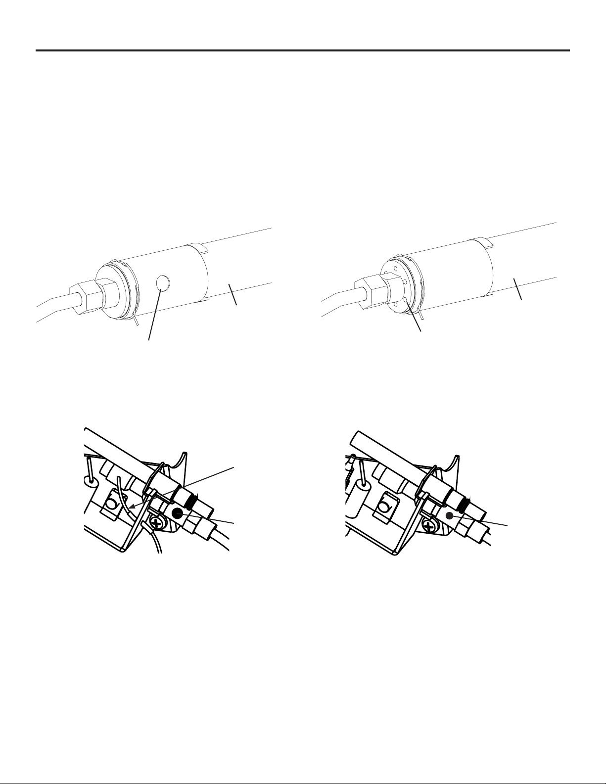
Clean the pilot assembly also. A yellow tip on the pilot ame indicates dust and dirt in the pilot
assembly. There is a small pilot air inlet hole about 2" from where the pilot ame comes out of the
pilot assembly (see Figures 34 or 35 depending on model). With the unit off, lightly blow air through
the air inlet hole. You may blow through a drinking straw if compressed air is not available.
Fig. 25.2 - NG Pilot Inlet Air Hole
Burner
Tube
Primary Air
Inlet Holes
Fig. 24.2 - NG Primary Air
Inlet Slot on Burner Tube
Fig. 25.1 - LP Pilot Inlet Air Hole
Thermal
Couple
Pilot Air
Inlet Hole
Pilot Air
Inlet Hole
31
TROUBLESHOOTING
WARNING: If you smell gas:
• Shut off gas supply.
• Do not try to light any appliance.
• Do not touch any electrical switch; do not use any phone in your building.
• Immediately call your gas supplier from a neighbor’s phone. Follow the gas supplier’s instructions.
• If you cannot reach your gas supplier, call the re department.
IMPORTANT: Operating heater where impurities in air exist may create odors. Cleaning supplies, paint, paint
remover, cigarette smoke, cements and glues, new carpet or textiles, etc., create fumes. These fumes may mix
with combustion air and create odors.
WARNING: Make sure that power is turned off before proceeding.
WARNING: Turn off and let cool before servicing. Only a qualied service person should service
and repair heater.
CAUTION: Never use a wire, needle, or similar object to clean ODS/pilot. This can damage ODS/ pilot unit.
PROBLEM POSSIBLE CAUSE CORRECTIVE ACTION
When ignitor button
is pressed in, there
is no spark at ODS/
pilot.
1. Ignitor electrode is
positioned wrong.
2. Ignitor electrode is broken.
3. Ignitor electrode is not
connected to ignitor cable.
4. Ignitor cable is pinched or
wet.
5. Damaged ignitor cable.
6. Bad piezo ignitor.
1. Replace electrode.
2. Replace electrode.
3. Replace ignitor cable
4. Free ignitor cable if pinched by any
metal or tubing. Keep ignitor cable dry.
5. Replace ignitor cable.
6. Replace piezo ignitor.
When ignitor button
is pressed in, there
is a spark at ODS/
pilot but no ignition.
1. Gas supply is turned off or
equipment shutoff valve is
closed.
2. Control knob not fully
pressed in while pressing
ignitor button.
3. Air in gas lines when
installed.
4. ODS / pilot is clogged.
5. Control knob not in PILOT
position.
6. Depleted gas supply (propane).
1. Turn on gas supply or open equipment
shutoff valve.
2. Fully press in control knob while
pressing ignitor button.
3. Continue holding down control knob.
Repeat igniting operation until air is
removed.
4. Clean ODS/pilot (see Care and
Maintenance, page 32) or replace
ODS/pilot assembly.
5. Turn control knob to PILOT position.
6. Contact local propane/LP gas company.
SERVICE HINTS
When Gas Pressure Is Too Low
• pilot will not stay lit
• burners will have delayed ignition
• replace will not produce specied heat
• for propane/LP units, propane/LP gas supply may be low
You may feel your gas pressure is too low. If so, contact your local natural or propane/LP gas supplier.

32
TROUBLESHOOTING
PROBLEM POSSIBLE CAUSE CORRECTIVE ACTION
ODS/pilot lights
but ame goes out
when control knob is
released.
1. Control knob is not fully
pressed in.
2. Control knob is not pressed
in long enough.
3. Equipment shutoff valve is
not fully open.
4. Thermocouple connection is
loose.
5. Thermocouple damaged.
6. Control valve damaged.
1. Press in control knob fully.
2. After ODS/pilot lights, keep control
knob pressed in 30 seconds.
3. Fully open equipment shutoff valve.
4. Hand tighten until snug, and then
tighten ¼ turn more.
5. Replace thermocouple.
6. Contact customer service.
Burner(s) does not
light afterODS/pilot
is lit.
1. Burner orice is clogged.
2. Burner orice diameter is
too small.
3. Inlet gas pressure is too low.
1. Clean burner orice (see Care and
Maintenance, page 32) or contact
customer service.
2. Contact customer service.
3. Contact your gas supplier.
Delayed ignition of
burner(s).
1. Manifold pressure is too low.
2. Burner orice is clogged.
3. There is a 1 minute delay for
the millivolt generator upon
startup.
1. Contact your gas supplier.
2. Clean burner (see Care and
Maintenance, page 32) or contact
customer service.
3. Allow the pilot ame to heat up the
millivolt generator for 1 minute.
Burner backring
during combustion.
1. Burner orice is clogged or
damaged.
2. Burner is damaged.
3. Gas regulator is damaged.
1. Clean burner orice (see Care and
Maintenance, page 32 or contact
customer service.
2. Contact dealer or customer service.
3. Replace gas regulator.
High yellow ame
during burner
combustion
1. Not enough air.
2. Gas regulator is defective.
3. Inlet gas pressure is too low.
1. Check burner for dirt and debris. If found, clean
burner (see Care and Maintenance, page 32).
2. Replace gas regulator.
3. Contact your gas supplier.
Gas odor during
combustion.
1. Foreign matter between
control valve and burner.
2. Gas leak. (See Warning
Statement at top of page 34).
1. Take apart gas tubing and remove foreign
matter.
2. Locate and correct all leaks (see “Check-
ing Gas Connections,” page 22).
Heater produces a
clicking/ticking noise
just after burner is lit
or shut off.
1. Metal is expanding while
heating or contracting
while cooling.
1. This is common with most heaters. If
noise is excessive, contact qualied
service technician.

33
TROUBLESHOOTING
PROBLEM POSSIBLE CAUSE CORRECTIVE ACTION
White powder resi-
due forming within
burner box or on
adjacent walls or
furniture.
1. When heated, the vapors
from furniture polish, wax,
carpet cleaners, etc., turn
into white powder residue.
1. Turn heater off when using furniture
polish, wax, carpet cleaner or similar
products.
Heater produces
unwanted odors.
1. Heater is burning vapors
from paint, hair spray, glues,
etc. See IMPORTANT state-
ment, page 34.
2. Gas leak. See Warning
Statement, page 34.
3. Low fuel supply.
1. Ventilate room. Stop using odor
causing products while heater is
running.
2. Locate and correct all leaks (see
“Checking Gas Connections,” page 22).
3. Rell supply tank (Propane /LP models).
Heater shuts off
in use (ODS oper-
ates).
1. Not enough fresh air is
available.
2. Low line pressure.
3. ODS/pilot is partially
clogged.
1. Open window and/or door for
ventilation.
2. Contact local gas supplier.
3. Clean ODS/pilot (see Care and
Maintenance, page 32).
Gas odor exists
even when control
knob is in OFF posi-
tion.
1. Gas leak. See Warning
Statement at top of page 34.
2. Control valve is
defective.
1. Locate and correct all leaks (see
“Checking Gas Connections”, page 22).
2. Contact customer service.
Moisture/conden-
sation noticed on
windows.
1. Not enough combustion/
ventilation air.
1. Refer to “Air for Combustion and
Ventilation” requirements, page 9-11.
Slight smoke or
odor during initial
operation
Heater produces
a whistling noise
when burner is lit.
1. Residues from
manufacturing process.
1. Problem will stop after a few hours of
operation.
1. Turning control knob to high (5)
position when burner is cold.
2. Air in gas line.
3. Air passageways on
heater are blocked.
4. Dirty or partially clogged
burner orice.
1. Turn control knob to low (1) position and
let warm up for a minute.
2. Operate burner until air is removed from
line. Have gas line checked by local
propane/LP gas company.
3. Observe minimum installation
clearances (Fig. 6, page 12)
4. Clean burner (see Care and Maintenance,
page 32) or contact customer service.
34
REPLACEMENT PARTS
For replacement parts, call our customer service department at 1-877-447-4768, 8:30 a.m. – 4:30 p.m.,
CST, Monday – Friday.
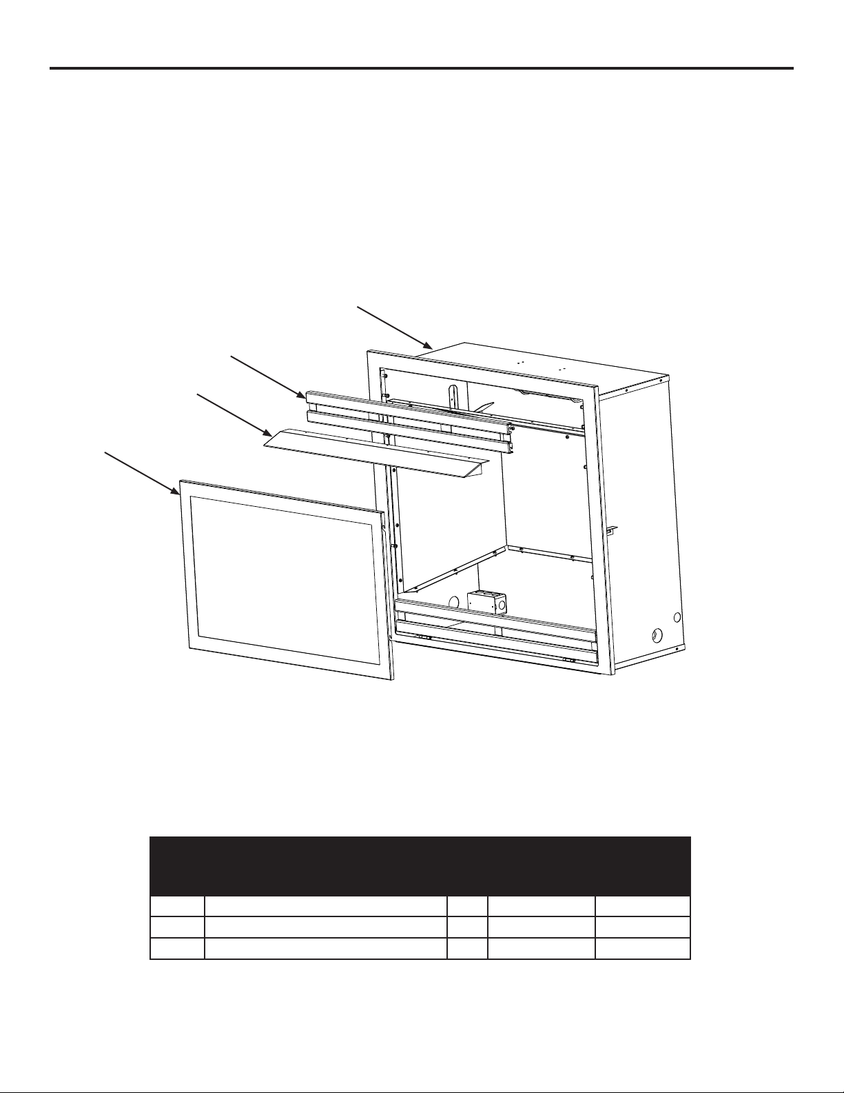
FIREBOX MODELS PHZCI28LP, PHZCI28NG, PHZCI32LP, PHZCI32NG
ITEM
NO.
DESCRIPTION QTY
PART NUMBER
PHZCI28LP
PHZCI28NG
PHZCI32LP
PHZCI32NG
1 TOP GRILLE 1 700-M1014B 700-L1014B
2 HOOD 1 700-M1012B 700-L1012B
3 WINDOW FRAME ASSEMBLY 1 700-AM1015 700-AL1015
Firebox
Top Grille
Hood
Screen
35
PHZCI32LP
PHZCI32NG
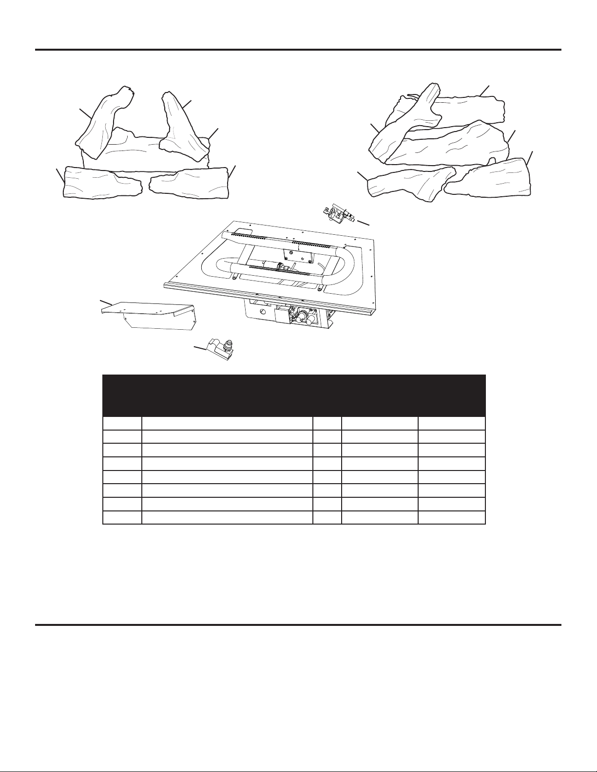
REPLACEMENT PARTS LIST
For replacement parts, call our customer service department at 1-877-447-4768, 8:30 a.m. – 4:30 p.m.,
CST, Monday – Friday.
ACCESSORIES
NOTICE: All accessories may not be available for all replace models.
THERMOSTAT-CONTROLLED BLOWER KIT - ZCB100 For all models. Provides better heat
distribution. Makes replace more efcient. Automatically turns off and on as needed.
1-1
1-2
1-3
1-5
1-4
1-1
1-2
1-3
1-5
1-4
* Item/version not shown in exploded parts diagram
ITEM
NO.
DESCRIPTION QTY
PART NUMBER
PHZCI28LP
PHZCI28NG
PHZCI32LP
PHZCI32NG
1 LOG SET (COMPLETE) 1 700-M1018 700-L1018
1-1 LOG 1 1 700-M1018-01 700-L1018-01
1-2 LOG 2 1 700-M1018-02 700-L1018-02
1-3 LOG 3 700-M1018-03 700-L1018-03
1-4 LOG 4 700-M1018-04 700-L1018-04
1-5 LOG 5 700-M1018-05 700-L1018-05
3 BLOWER INSTALLATION BRACKET 1 80-90-123 80-90-123
4 IGNITOR 1 301-01015-06 301-01015-06
PHZCI28LP
PHZCI28NG
2-1
2-2
4
3

36
37
33
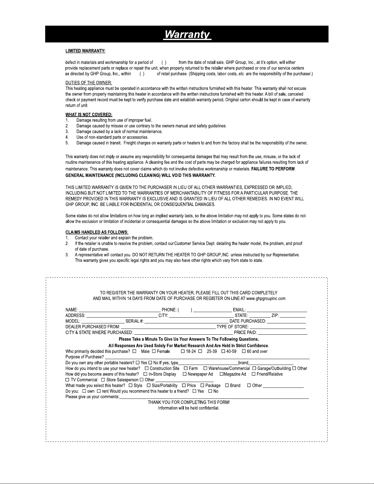
This limited warranty is extended to the original retail purchaser of this heater and warrants against any
2
2
two
two
years
years
38
34
GHP Group, Inc.
6440 W Howard St
Niles, IL 60714-3302
Tel: (877) 447-4768
www.ghpgroupinc.com
GHP Group, Inc.
6440 W Howard St
Niles, IL 60714-3302
