1
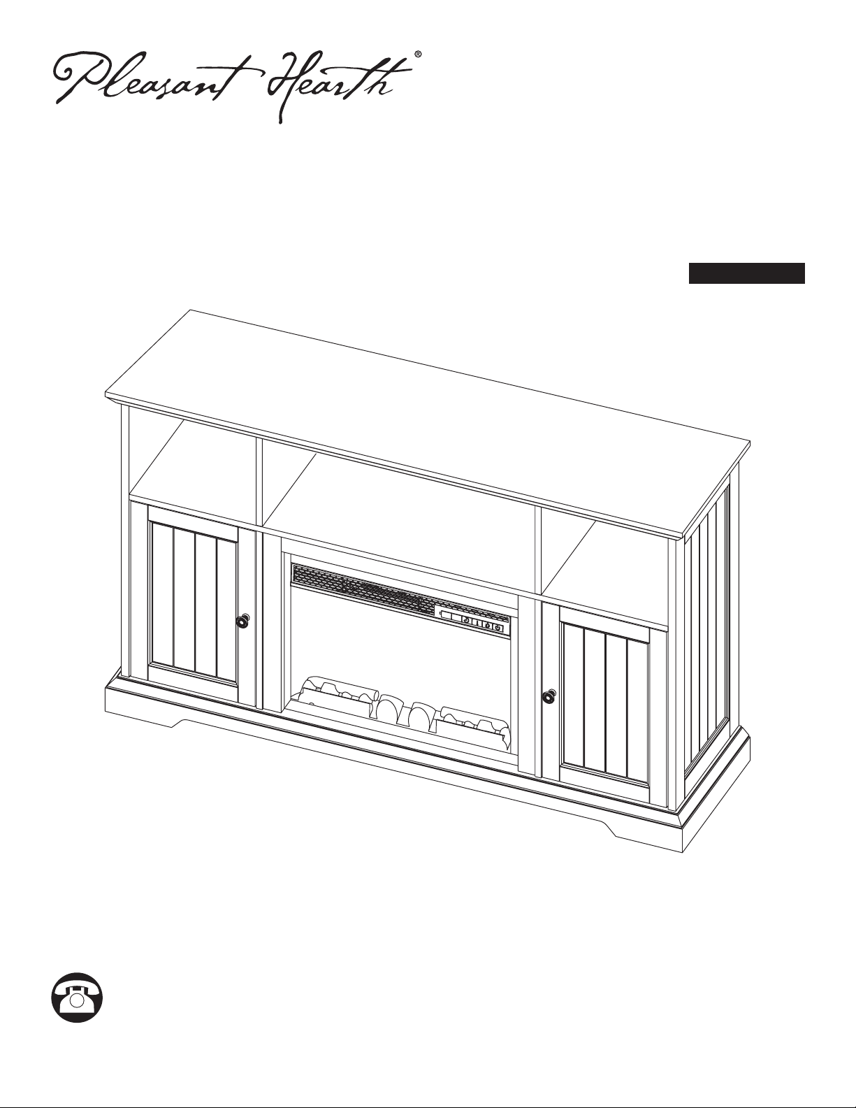
MODEL #230-752-242 / #230-752-924 / #230-752-50
ATTACH YOUR RECEIPT HERE
Serial Number ________________________________ Purchase Date _________________________________
200514
Questions, problems, missing parts?
Before returning to your retailer, call our customer service department at 1-877-447-4768,
8:00 a.m. – 4:30 p.m. CST, Monday – Friday or email us at [email protected]
Español p. 9
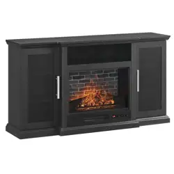
HENSLEY ELECTRIC FIREPLACE

2
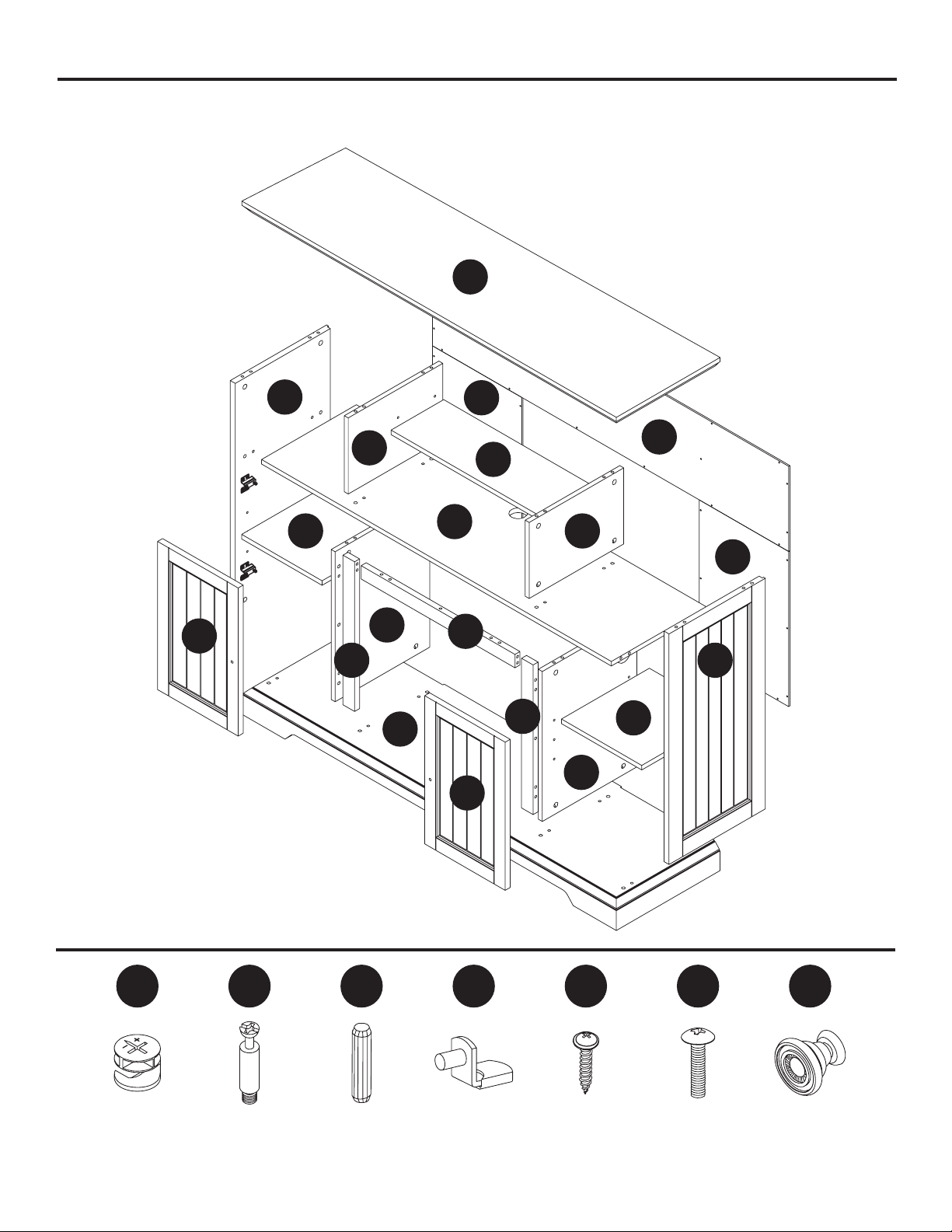
PACKAGE CONTENTS
HARDWARE CONTENTS
Cam Lock
Qty. 37
Dowel
Qty. 38
Cam Bolt
Qty. 37
GGFFEEDDCCBBAA
Back Panel
Screw
Qty. 34
Bolt
Qty. 2
Handle
Qty. 2
Shelf Pin
Qty. 12
A
J
K
K
H
G
F
C
D
E
N
N
P
L
Q
R
M
B
S
T
Carefully remove all pieces from carton and make sure that you have all parts listed.
If you are missing parts, please call GHP customer service at 1-877-447-4768.

3
PACKAGE CONTENTS
PART DESCRIPTION QTY. 230-752-50 230-752-924 230-752-242
A Top Panel 1 20-12-864 20-12-882 20-12-900
B Base Panel 1 20-12-865 20-12-883 20-12-901
C Media Shelf 1 20-12-866 20-12-884 20-12-902
D Left Side Panel 1 20-12-867 20-12-885 20-12-903
E Right Side Panel 1 20-12-868 20-12-886 20-12-904
F Upper Left Partition 1 20-12-869 20-12-887 20-12-905
G Upper Right Partition 1 20-12-870 20-12-888 20-12-906
H Adjustable Media Shelf 1 20-12-871 20-12-889 20-12-907
I Upper Back Panel 1 20-12-872 20-12-890 20-12-908
J Side Back Panel 2 20-12-873 20-12-891 20-12-909
K Lower Left Partition 1 20-12-874 20-12-892 20-12-910
L Lower Right Partition 1 20-12-875 20-12-893 20-12-911
M Adjustable Shelf 2 20-12-876 20-12-894 20-12-912
N Upper Rail 1 20-12-877 20-12-895 20-12-913
O Left Rail 1 20-12-878 20-12-896 20-12-914
P Right Rail 1 20-12-879 20-12-897 20-12-915
Q Left Door 1 20-12-880 20-12-898 20-12-916
R Right Door 1 20-12-881 20-12-899 20-12-917
Hardware 1 20-09-709
Some parts and specications may change without notice.
4
ASSEMBLY INSTRUCTIONS
1
3
2
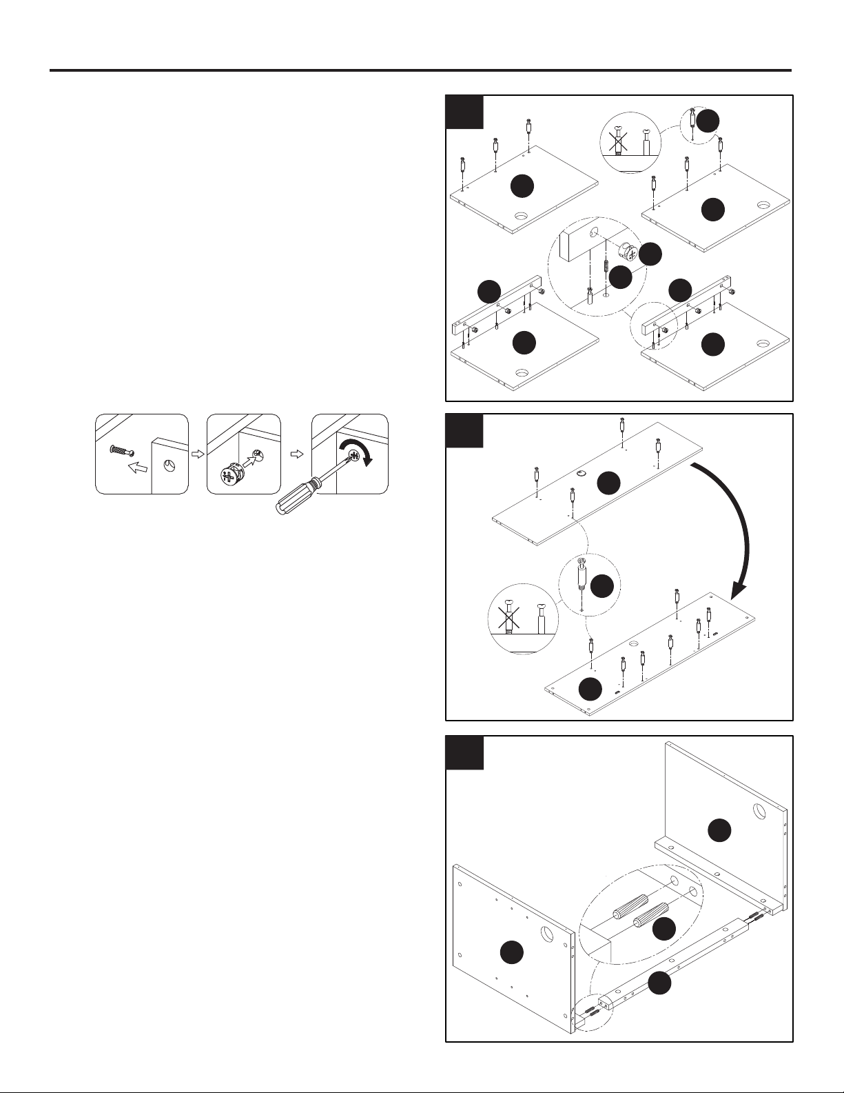
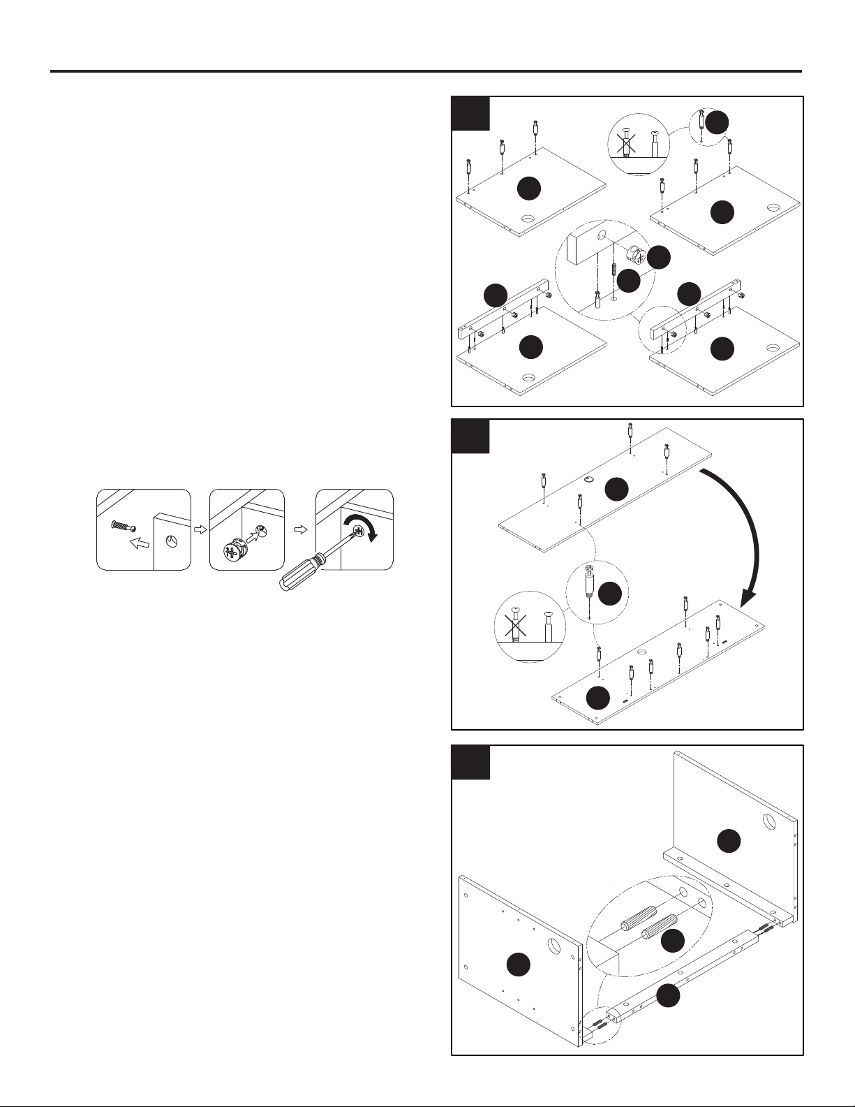
1. Locate the left and right lower partitions (L & M)
and place them on a soft surface to protect the
nish. Insert three cam bolts (BB) into the lower
right partition (M). Fully tighten the cam bolts (BB)
with a screwdriver. Insert two dowels (CC) into
the unthreaded holes on the lower right partition
(M) and follow below dowel assembling guide.
Attach the right rail (R) to lower right partition (M)
by using three cam locks (AA) as shown in the
cam lock assembly guide. Insert three cam bolts
(BB) into the lower left partition (L). Fully tighten
the cam bolts (BB) with a screwdriver. Insert two
dowels (CC) into the unthreaded holes on the
lower left partition (L) and follow below dowel
assembling guide. Attach the left rail (Q) to lower
left partition (L) by using three cam locks (AA) as
shown in the cam lock assembly guide.
2. Locate the media shelf (C) and place them on
a soft surface to protect the nish. Insert four
cam bolts (BB) into the top of the media shelf
(C). Fully tighten the cam bolts (BB) with a
screwdriver. Turn the media shelf (C) and
insert seven cam bolts (BB) into the media
shelf (C). Fully tighten the cam bolts (BB)
with a screwdriver.
3. Attached the left and right lower partitions
(L & M) to upper rail (P) by inserting four
wood dowels (CC) into the unthreaded holes
on the inside face of the left and right lower
partitions (L & M).
L
M
C
M
L
P
C
M
L
Q
R
BB
BB
CC
AA
CC
5
5
ASSEMBLY INSTRUCTIONS
4
6
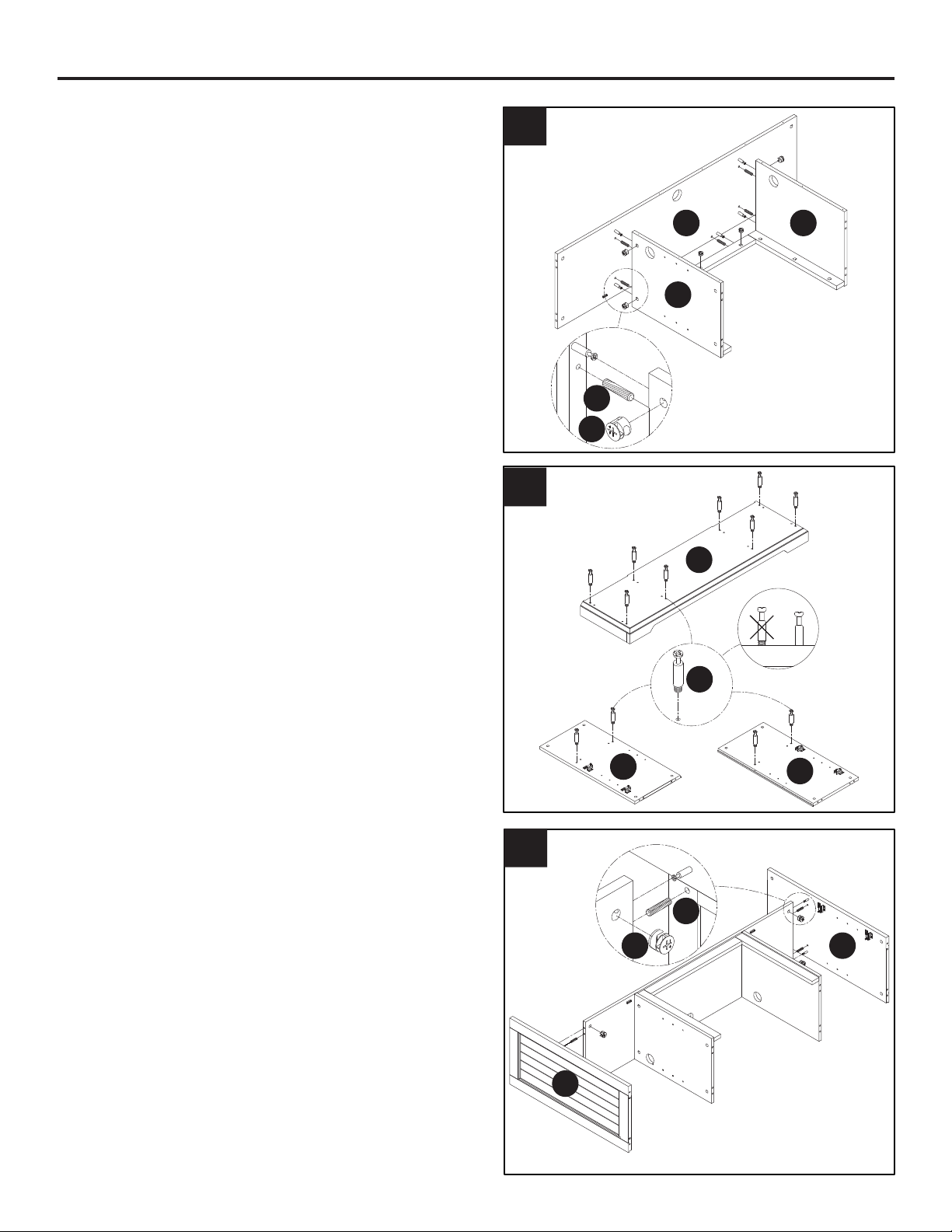
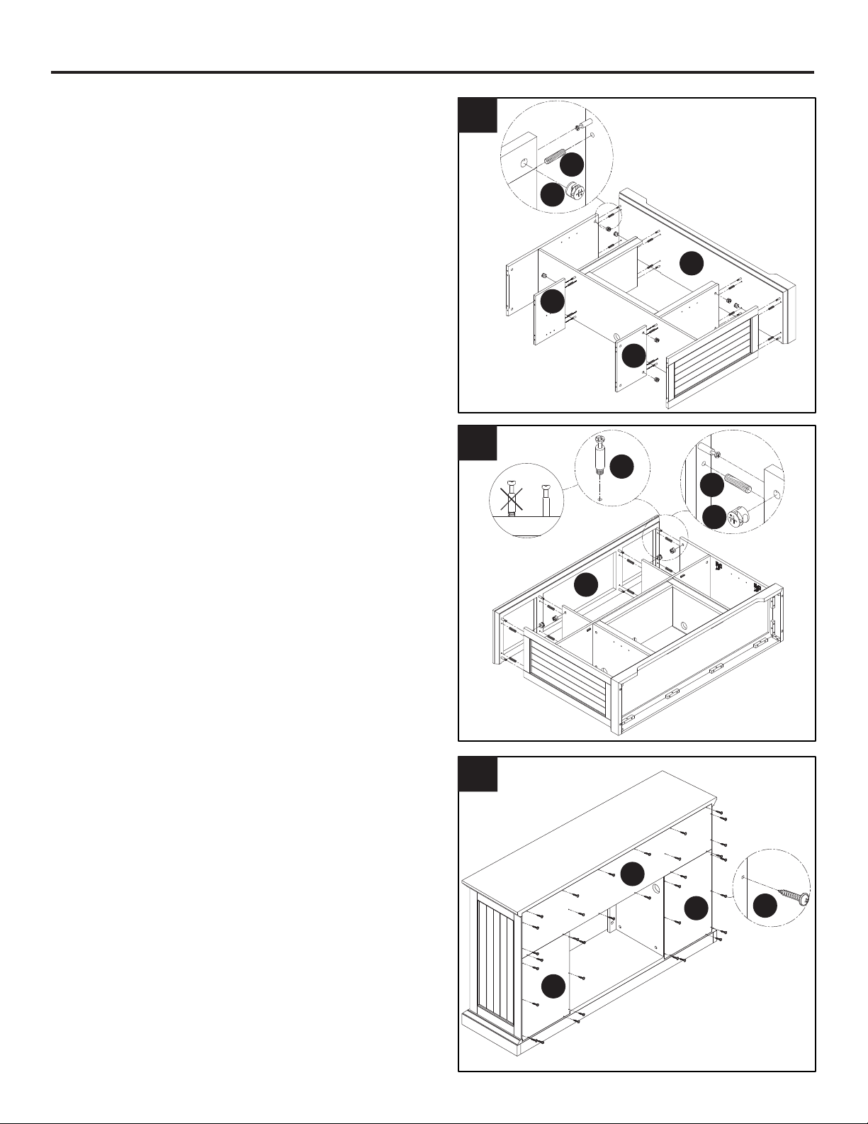
4. Insert six dowels (CC) into the unthreaded
holes on the lower right partition (M), lower
left partition (L) and top rail as shown in the
diagram. Attach the lower right partition (M),
lower left partition (L) and top rail assembly to
the media shelf (C) by using seven cam locks
(AA) as shown in the cam lock assembly
guide.
5. Insert twelve cam bolts (BB) into the base
panel (B). Fully tighten the cam bolts (BB)
with a screwdriver.
6. Insert four dowels (CC) into the unthreaded
holes on the left side panel (D) and right side
panel (E) as shown in the diagram. Attach the
left side panel (D) and right side panel (E) to
the media shelf (C) by using four cam locks
(AA) as shown in the cam lock assembly
guide.
M
LC
CC
BB
CC
E
D
AA
B
E
D
AA

6
ASSEMBLY INSTRUCTIONS
7
9
8
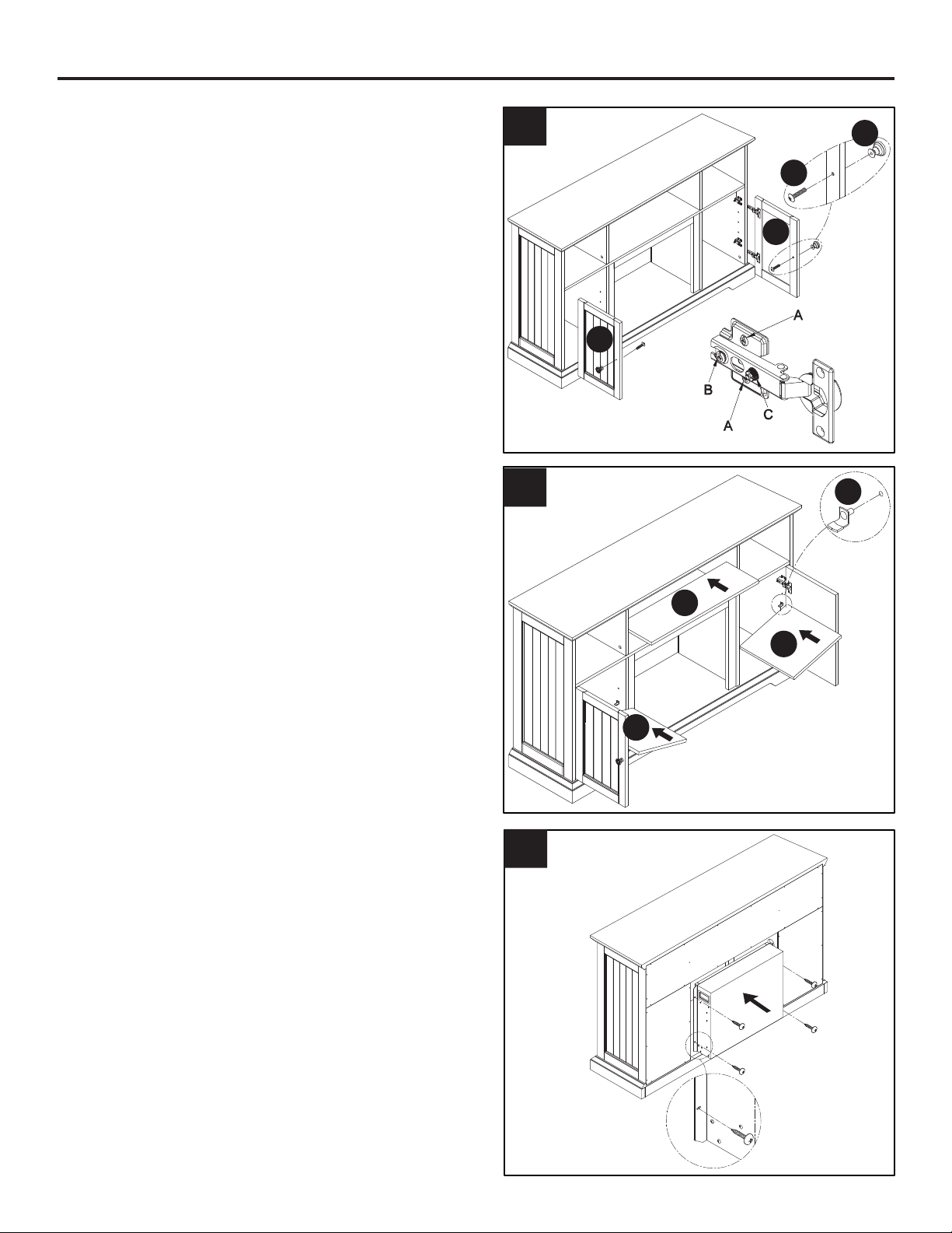
7. Attach the upper right partition (R) and upper left
partition (F) to the media shelf by inserting two
dowels each into the unthreaded holes as shown
in the diagram. Insert four cam locks (AA) as
shown in the cam lock assembly guide into the
upper right partition (R) and upper left partition
(F). Attach the mantel assembly to the base
panel (B) by inserting eight dowels each into the
unthreaded holes as shown in the diagram. Insert
eight cam locks (AA) as shown in the cam lock
assembly guide into mantel assembly as shown
in the diagram.
8. Insert eight wood dowels (CC) into the
unthreaded holes on the bottom of the top
panel (A) as shown in the diagram. Insert
eight cam bolts (BB) into left side and right
side panels (D & E). Fully tighten the cam
bolts (BB) with a screwdriver. Insert eight
cam locks (AA) as shown in the cam lock
assembly guide into mantel assembly as
shown in the diagram.
9. Locate the two side back panels (K) and the
upper back panel (J) and line them up to
the back of the mantel with the nished side
facing in. Insert and tighten thirty-four back
panel screws (EE) to attach the two side back
panels (K) and the upper back panel (J) to
mantel.
CC
BB
CC
AA
A
J
K
K
EE
B
G
F
AA
7
ASSEMBLY INSTRUCTIONS
10
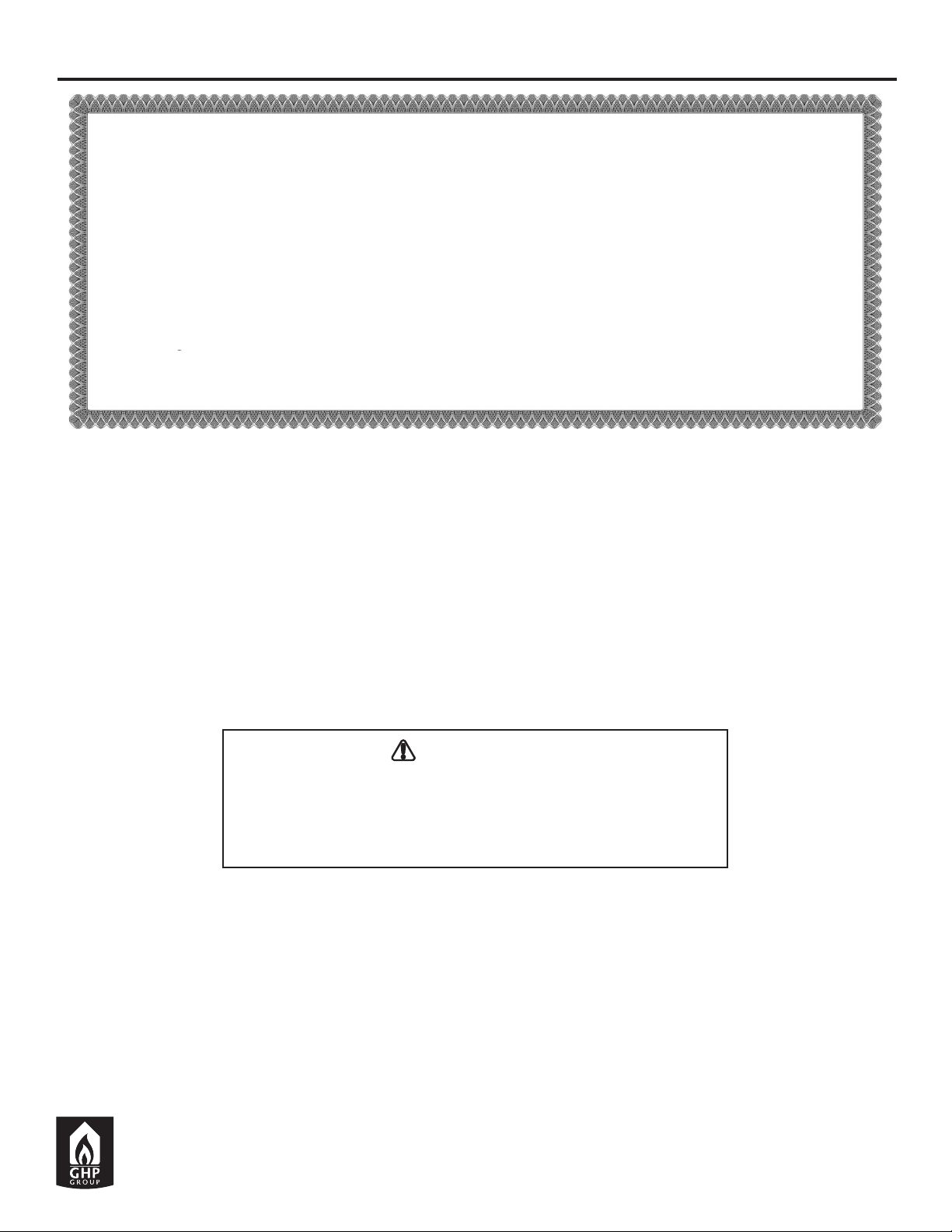
10. Locate the left and right door (S & T). Attach
the handle (GG) to left and right door (S
& T) by inserting a bolt (FF) through the
hole in the door. Tighten the bolt (FF) with
a screwdriver. Line up hinge cups on the
cabinet doors (S & T) with the hinge plates
in the left and right side panels of the media
console. Slide the hinge plates over the
hinge cups as shown and tighten them with
the screws provided on the hinge plates.
Adjust the vertical height by loosing the four
“A” screws, in the diagram, on both hinges.
Two of them are usually in slotted holds
which allows you to adjust up or down by
a few mm. Then tighten the screws again.
Adjust the depth by loosing “B” screw, in
the diagram, and adjust the door. If the door
cannot be adjusted, please loosen screw
“C”, as shown in the diagram, then try again.
Tighten screw “B” and “C” as shown in the
diagram. Adjust the cabinet doors sideways
by turning the screw “C” on both hinges on
each door.
11. Insert twelve shelf pins (DD) into the interior
of the side panels and media shelf. Insert
the pins parallel to one another to ensure
the shelves are level. Carefully place four
adjustable shelves (N) onto the shelf pins
(DD). Carefully place the adjustable media
shelf (H) on the shelf pins (DD).
12. Insert the rebox into the mantel through
the back opening. Push the rebox forward
through the back opening until the metal trim
of the rebox in ush with the side panels.
Once the rebox is in position attach the two
mounting brackets included with the rebox
by inserting and tightening four screws
through the mounting brackets into the
rebox and the base panel.
11
12
S
T
FF
DD
N
N
H
GG
8
GHP Group, Inc.
6440 W. Howard St. • Niles, IL • 60714-3302
271 Massey Road • Guelph, ON • N1K 1B2
ONE YEAR LIMITED WARRANTY
If within one year from the date of original purchase, this item fails due to a defect in material or
workmanship, we will replace or repair at our option, free of charge. To order parts or obtain warranty
service, call 1-877-447-4768, 8:00 a.m. – 4:30 p.m. CST, Monday – Friday. This warranty does not
cover defects resulting from improper or abnormal use, misuse, accident, or alteration. Failure to follow
all instructions in the owner’s manual will also void this warranty. GHP Group, Inc. will not be liable for
incidental or consequential damages. Some states do not allow the exclsion or limitation of incidental or
consequential damages, so the above limitation or exclusion of incidental or consequential damages may
not apply to you. This warranty gives you specic legal rights and you may also have other rights which
vary from state to state.
Notice to the Customer
Our quality furniture is built keeping tradition in mind. Variations in actual wood color and nishes which may result
from natural characteristics of the wood, such as grain patterns, mineral streaks and the like, are not considered
defects. As wood continues to move and age you may notice these slight differences in color, even on different
parts of any individual unit. Sound knots and slight surface cracks are true personality of a quality piece of wood
furniture.
There are several practices we reccomend so that you may maintain your new furniture in top condition. First of all,
to maintain the nish, you should clean with a soft, slightly damp cloth and buff with a dry cloth. Secondly, wood
furniture should never be dragged across a oor. The added stress from dragging the unit may cause the dragged
edge to splinter or it may cause some joints to loosen.
Please contact us for any questions or concerns you may have regarding your new piece of furniture.
ONE YEAR LIMITED WARRANTY
Printed in China
6440 W. Howard St., Niles, IL 60714-3302
271 Massey Road, Guelph, ON N1K 1B2
877-447-4768
WARNING
This Product can expose you to chemicals including Diisononyl
phthalate (DINP) which is known to the State of California to cause
cancer and Di-isodecyl phthalates (DIDP) which is known to the
State of California to cause birth defects or other reproductive harm.
For more information go to www.p65Warnings.ca.gov
9
ADJUNTE SU RECIBO AQUÍ
Número de serie ________________________________ Fecha de compra _________________________________
¿Preguntas, problemas, piezas faltantes?
Antes de volver a la tienda, llame a nuestro departamento de servicio al cliente al 1-877-447-4768,
de lunes a viernes de 8:00 a.m. a 4:30 p.m., hora central estándar o envíenos un correo electrónico a
CHIMENEA ELECTRICA HENSLEY
MODELO #230-752-242 / #230-752-924 / #230-752-50
10
CONTENIDO DEL EMPAQUE
HERRAJE INCLUIDO
Cerraduras
de leva
Cant. 37
Clavija
Cant. 38
Tornillos de
leva
Cant. 37
GGFFEEDDCCBBAA
Perno
Cant. 2
Manija
Cant. 2
Pasadores
de estante
Cant. 12
A
J
K
K
H
G
F
C
D
E
N
N
P
L
Q
R
M
B
S
T
Retire con cuidado todas las piezas de la caja y asegúrese de que usted tiene todas las piezas de la lista.
Si le faltan piezas, por favor llame a nuestro departamento de servicio al cliente de GHP al 1-877-447-4768.
Tornillo del
panel posterior
Cant. 34

11
CONTENIDO DEL EMPAQUE
PIEZA DESCRIPCIÓN CANT. 230-752-50 230-752-924 230-752-242
A Panel superior 1 20-12-864 20-12-882 20-12-900
B Panel base 1 20-12-865 20-12-883 20-12-901
C Estante de medios 1 20-12-866 20-12-884 20-12-902
D Panel lateral izquierdo 1 20-12-867 20-12-885 20-12-903
E Panel lateral derecho 1 20-12-868 20-12-886 20-12-904
F Partición superior izquierda 1 20-12-869 20-12-887 20-12-905
G Partición superior derecha 1 20-12-870 20-12-888 20-12-906
H Estante de medios ajustable 1 20-12-871 20-12-889 20-12-907
I Panel posterior superior 1 20-12-872 20-12-890 20-12-908
J Panel posterior lateral 2 20-12-873 20-12-891 20-12-909
K Partición inferior izquierda 1 20-12-874 20-12-892 20-12-910
L Partición inferior derecha 1 20-12-875 20-12-893 20-12-911
M Estante ajustable 2 20-12-876 20-12-894 20-12-912
N Carril superior 1 20-12-877 20-12-895 20-12-913
O Carril izquierdo 1 20-12-878 20-12-896 20-12-914
P Carril derecho 1 20-12-879 20-12-897 20-12-915
Q Puerta izquierda 1 20-12-880 20-12-898 20-12-916
R Puerta derecha 1 20-12-881 20-12-899 20-12-917
Herraje 1 20-09-709
Algunas partes y las especicaciones pueden cambiar sin previo aviso.
12
INSTRUCCIONES DE MONTAJE
1
3
2
1. Localice las particiones inferiores izquierda
y derecha (L y M) y colóquelas sobre una
supercie suave para proteger el acabado.
Inserte tres pernos de leva (BB) en la partición
inferior derecha (M). Apriete completamente
los pernos de leva (BB) con un destornillador.
Inserte dos tacos (CC) en los oricios sin rosca
en la partición inferior derecha (M) y siga la guía
de montaje de tacos debajo. Fije el riel derecho
(R) a la partición inferior derecha (M) usando
tres bloqueos de leva (AA) como se muestra
en la guía de ensamblaje del bloqueo de leva.
Inserte tres pernos de leva (BB) en la partición
inferior izquierda (L). Apriete completamente los
pernos de leva (BB) con un destornillador. Inserte
dos clavijas (CC) en los oricios sin rosca en la
partición inferior izquierda (L) y siga la guía de
montaje de clavijas debajo. Fije el riel izquierdo
(Q) a la partición inferior izquierda (L) usando tres
bloqueos de leva (AA) como se muestra en la
guía de ensamblaje del bloqueo de leva.
2. Ubique el estante de medios (C) y colóquelos
sobre una supercie suave para proteger el
acabado. Inserte cuatro pernos de leva (BB)
en la parte superior del estante de medios
(C). Apriete completamente los pernos de
leva (BB) con un destornillador. Gire el
estante de medios (C) e inserte siete pernos
de leva (BB) en el estante de medios (C).
Apriete completamente los pernos de leva
(BB) con un destornillador.
3. Sujete las particiones inferiores izquierda y
derecha (L y M) al riel superior (P) insertando
cuatro clavijas de madera (CC) en los oricios
sin rosca en la cara interior de las particiones
inferiores izquierda y derecha (L y M).
L
M
C
M
L
P
C
M
L
Q
R
BB
BB
CC
AA
CC

13
INSTRUCCIONES DE MONTAJE
5
4
6
4. Inserte seis clavijas (CC) en los oricios sin
rosca en la partición inferior derecha (M), la
partición inferior izquierda (L) y el riel superior
como se muestra en el diagrama. Una la
partición inferior derecha (M), la partición
inferior izquierda (L) y el ensamblaje del riel
superior al estante de medios (C) utilizando
siete bloqueos de leva (AA) como se muestra
en la guía del ensamblaje del bloqueo de
leva.
5. Inserte doce pernos de leva (BB) en el panel
base (B). Apriete completamente los pernos
de leva (BB) con un destornillador.
6. Inserte cuatro clavijas (CC) en los oricios
sin rosca del panel lateral izquierdo (D) y el
panel lateral derecho (E) como se muestra
en el diagrama. Fije el panel lateral izquierdo
(D) y el panel lateral derecho (E) al estante
de medios (C) utilizando cuatro bloqueos
de leva (AA) como se muestra en la guía de
montaje del bloqueo de leva.
M
LC
CC
BB
CC
E
D
AA
B
E
D
AA
14
INSTRUCCIONES DE MONTAJE
7
9
8
7. Fije la partición superior derecha (R) y la
partición superior izquierda (F) al estante de
medios insertando dos clavijas cada una en
los oricios sin rosca como se muestra en el
diagrama. Inserte cuatro bloqueos de levas
(AA) como se muestra en la guía de ensamblaje
del bloqueo de levas en la partición superior
derecha (R) y la partición superior izquierda
(F). Fije el ensamblaje de la repisa al panel
base (B) insertando ocho clavijas cada uno en
los agujeros sin rosca como se muestra en el
diagrama. Inserte ocho bloqueos de leva (AA)
como se muestra en la guía del conjunto del
bloqueo de la leva en el conjunto de la repisa
como se muestra en el diagrama.
8. Inserte ocho clavijas de madera (CC) en los
agujeros sin rosca en la parte inferior del
panel superior (A) como se muestra en el
diagrama. Inserte ocho pernos de leva (BB)
en los paneles laterales izquierdo y derecho
(D y E). Apriete completamente los pernos de
leva (BB) con un destornillador. Inserte ocho
bloqueos de leva (AA) como se muestra en la
guía del conjunto del bloqueo de la leva en el
conjunto de la repisa como se muestra en el
diagrama.
9. Localice los dos paneles posteriores
laterales (K) y el panel posterior superior (J)
y alinéelos a la parte posterior de la repisa
con el lado terminado hacia adentro. Inserte
y apriete treinta y cuatro tornillos del panel
posterior (EE) para jar los dos paneles
posteriores laterales (K) y el panel posterior
superior (J) a la repisa de la chimenea.
CC
BB
CC
AA
A
J
K
K
EE
B
G
F
AA

15
INSTRUCCIONES DE MONTAJE
10
10. Localice la puerta izquierda y derecha (S &
T). Fije la manija (GG) a la puerta izquierda
y derecha (S & T) insertando un perno (FF)
a través del oricio en la puerta. Apriete el
tornillo (FF) con un destornillador. Alinee
las copas de las bisagras en las puertas
del gabinete (S & T) con las placas de las
bisagras en los paneles laterales izquierdo
y derecho de la consola de medios.
Deslice las placas de las bisagras sobre
las copas de las bisagras como se muestra
y apriételas con los tornillos provistos en
las placas de las bisagras. Ajuste la altura
vertical aojando los cuatro tornillos “A”,
en el diagrama, en ambas bisagras. Dos
de ellos generalmente están en bodegas
ranuradas que le permiten ajustar hacia
arriba o hacia abajo unos pocos mm. Luego
apriete los tornillos nuevamente. Ajuste
la profundidad aojando el tornillo “B”, en
el diagrama, y ajuste la puerta. Si no se
puede ajustar la puerta, aoje el tornillo “C”,
como se muestra en el diagrama, e intente
nuevamente. Apriete los tornillos “B” y “C”
como se muestra en el diagrama. Ajuste
las puertas del gabinete de lado girando
el tornillo “C” en ambas bisagras de cada
puerta.
11. Inserte doce pasadores de estante (DD)
en el interior de los paneles laterales y el
estante de medios. Inserte los pasadores
paralelos entre sí para asegurarse de que
los estantes estén nivelados. Coloque con
cuidado cuatro estantes ajustables (N) en
los pasadores del estante (DD). Coloque
con cuidado el estante de medios ajustable
(H) en los pasadores del estante (DD).
12. Inserte la caja de fuego en la repisa a través
de la abertura posterior. Empuje la caja de
fuego hacia adelante a través de la abertura
posterior hasta que el borde metálico de la
caja de fuego quede al ras con los paneles
laterales. Una vez que la caja de fuego esté
en posición, je los dos soportes de montaje
incluidos con la caja de fuego insertando
y apretando cuatro tornillos a través de los
soportes de montaje en la caja de fuego y el
panel base.
11
12
S
T
FF
DD
N
N
H
GG
16
AVISO PARA EL CONSUMIDOR
Nuestros muebles de calidad de fabrican teniendo en mente la tradición. Las variaciones en el color y
acabados de la madera, que pueden ser resultado de las características naturales de la misma, tales
como el patrón de las vetas, manchas minerales y otros similares, no se consideran defectos. A medida
que la madera continúa moviéndose y envejeciendo, usted podrá notar estas ligeras diferencias en color,
incluso en diferentes partes de una pieza individual. Los nudos profundos y las pequeñas rajaduras en la
supercie indican la personalidad verdadera de una pieza de madera de buena calidad.
Existen varias formas que recomendamos para que mantenga sus muebles nuevos en las mejores
condiciones. Primero que todo, para mantener el acabado debe limpiar con un paño suave, ligeramente
húmedo, y pulir con un paño seco. Además, los muebles de madera nunca deben arratrarse por el piso.
el estrés agregado de arrastrar la unidad puede causar que la parte arrastrada se astille o que se aoje
una unión.
Comuníquese con nostoros si tiene alguna pregunta o preocupación acerca de su nuevo mueble.
GARANTÍA LIMITADA DE UN AÑO
Si un lapso de un año a partir de la fecha de compra original este artículo falla debido a un defecto en el
material o la mano de obra, lo reemplzaremos o repararemos sin cargos a nuestra discreción. Para hacer
un pedido de las piezas o para obtener el servicio de garantía, llame al 1-877-447-4768, 8:00 a.m. – 4:30
p.m.,
hora central estándar
, Monday – Friday. Esta garantía no cubre defectos que sean producto de un uso
incorrecto o anormal, uso indebido, accidente o alteración. No seguir todas las instrucciones del manual
del propietario también anulará esta garantía. El fabricante no será reponsable de daños accidentales o
resultantes. Algunos estados no permiten la exclusión o limitación de los daños accidentales o resultantes,
de modo que las limitaciones anteriores pueden no aplicarse en su caso. Esta garantía le otorga derechos
legales especícos, pero podría tener también otros derechos que verían según el estado.
GHP Group, Inc.
6440 W. Howard St. • Niles, IL 60714-3302
271 Massey Road • Guelph, ON • N1K 1B2
UN AÑO DE GARANTÍA LIMITADA
6440 W. Howard St., Niles, IL 60714-3302
271 Massey Road, Guelph, ON N1K 1B2
877-447-4768
ADVERTENCIA
Este producto puede exponerlo a usted a agentes químicos
incluyendo ftalato de diisononilo (DINP), reconocido por el estado de
California como causante de cáncer, así como ftalatos de diisodecilo
(DIDP), reconocidos por el estado de California como causantes de
defectos congénitos y otros daños al sistema reproductor.
Para obtener más información, visite www.p65Warnings.ca.gov