ATTACH YOUR RECEIPT HERE
Serial Number ________________________________ Purchase Date _________________________________
250715
Questions, problems, missing parts?
Before returning to your retailer, call our customer service department at 1-877-447-4768,
8:00 a.m. – 4:30 p.m. CST, Monday – Friday or email us at [email protected]
Español p. 24
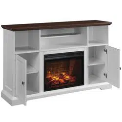
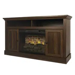
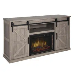
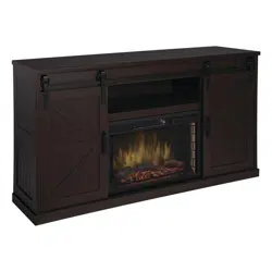
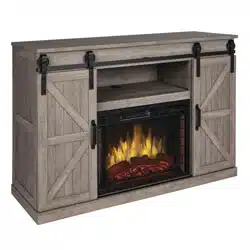
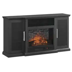
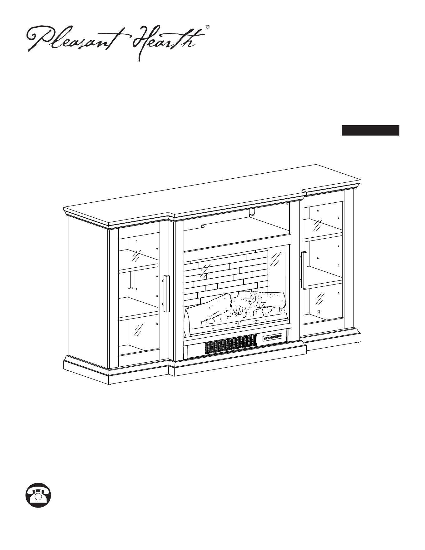
KENSINGTON TV STAND
WITH ELECTRIC FIREPLACE
Model #237-807-359
Insert Model #S03-23CKD-R
F/C
H
2
Table of Contents. . . . . . . . . . . . . . . . . . . . . . . . . . . . . 2
Safety Information ............................2
Electrical Connection .........................3
Grounding Instructions .......................3
Remote Control .............................4
Maximum Weight Capacity ....................4
Package Contents ............................5
Planning Assembly ...........................7
Assembly Instructions .........................8
Operating Instructions ........................16
Care and Cleaning. . . . . . . . . . . . . . . . . . . . . . . . . . . 19
Troubleshooting .............................20
Replacement Parts ..........................21
Service Parts ...............................22
Warranty ..................................23
IMPORTANT INSTRUCTIONS
When using electrical appliances, basic precautions should always be followed to reduce the risk of re, electric shock
and injury to persons, including the following:
WARNING
• This appliance is hot when in use. To avoid burns, DO NOT let bare skin touch hot surfaces. Keep combustible
material, such as furniture, pillows, bedding papers, clothes and curtains at least 3 feet from this appliance and keep
them away from the sides and rear.
• Extreme caution is necessary when any heater is used by or near children or individuals with disabilities and
whenever the replace is left operating and unattended.
• DO NOT run cord under carpeting. DO NOT cover cord with throw rugs, runners, or similar coverings.
• DO NOT route cord under furniture or appliances. Arrange cord away from trafc areas and where it will not be tripped
over.
• DO NOT insert or allow foreign objects to enter any ventilation or exhaust opening as this may cause an electric shock
or re, or damage the appliance.
• This appliance has hot and arcing or sparking parts inside. DO NOT use it in areas where gasoline, paint or ammable
vapors or liquids are used or stored. This replace should not be used as a drying rack for clothing. Christmas
stockings or decorations should not be hung in the area of it.
• Use this appliance only as described in the manual. Any other use is NOT recommended by the manufacturer and
may cause re, electric shock or injury to persons.
• Reduce the risk of burns, re, electrical shock, or injury to persons:
• Unplug from outlet before putting on or taking off parts
• Close supervision is necessary when this furnishing is used by, or near children, invalids, or disable persons.
• Use this furnishing only for its intended use as described in these instructions. Do not use attachments not
recommended by the manufacturer.
• Keep the cord away from heated surfaces.
• Never operate the furnishing with the air openings blocked. Keep the air openings free of lint, hair and like.
• Never drop or insert any object into any opening.
• Do not operate where aerosol (spray) products are being used or where oxygen is being administered.
• To disconnect, turn all controls to the off position, then remove plug from outlet.
Risk of Electric Shock: Connect this furnishing to a properly grounded outlet only. See Grounding Instructions.
Risk of Electric Shock - Fire and Injury: Review the assembly instruction to conrm that the appropriate critical
components and accessories are being used with the furnishing.
DANGER
To reduce the electrical shock, tipping and instability of the product.
• Read all instructions before installing or using this heater.
• If the information in this manual is not followed exactly, an electric shock or re may result causing property damage,
personal injury or loss of life.
• ALWAYS unplug this appliance/furnishing from the electrical outlet before cleaning or servicing.
TABLE OF CONTENTS
SAFETY INFORMATION
3
CAUTION
• DO NOT operate any heater with a damaged cord or plug or after the heater malfunctions.
• DO NOT operate any heater if it has been dropped or damaged in any manner. Disconnect power at service panel
and have heater inspected by a reputable electrician before reusing.
• Any repairs to this replace should be carried out by a qualied service person.
• Under no circumstances should this replace be modied. Parts having to be removed for servicing must be replaced
prior to operating this replace again.
• Household use only
• Do not use outdoors
• This heater is not intended for use in bathrooms, laundry areas and similar indoor locations. Never place heater where
it may fall into a bathtub or other water container.
• To disconnect this appliance, turn controls to the OFF position, then remove plug form outlet.
• Only connect to properly grounded outlets.
• This appliance, when installed, must be electrically grounded in accordance with local codes, with the current CSA
C22.1 Canadian Electrical Code or follow U.S.A Installations, follow local codes and the National Electrical Code,
ANSI/NFPA N0.70.
• To prevent a possible re, DO NOT block air intakes or exhaust in any manner. DO NOT use on soft surfaces, like
bed, where opening may become blocked.
• The heaters MUST NOT be located immediately below a socket-outlet.
• ALWAYS plug heaters directly into a wall outlet/ receptacle. NEVER use with an extension cord or
relocatable power tap (outlet/ power strip).
• DO NOT slide insert on top of wood to avoid scratching wood surface.
• DO NOT place any object on top of the insert or block the air intakes/ vents as this can cause the unit to overheat and
could cause a re.
ELECTRICAL CONNECTION
• A 15-Amp, 120-volt, 60 Hz circuit with a properly grounded outlet is required. Preferably, the replace will be on a
dedicated circuit as other appliances on the same circuit may cause the circuit breaker to trip or the fuse to blow when
the heater is in operation. The unit comes standard with 6-ft. three-wire cord, exiting from the rear of the replace. DO
NOT exceed the current rating of the current tap.
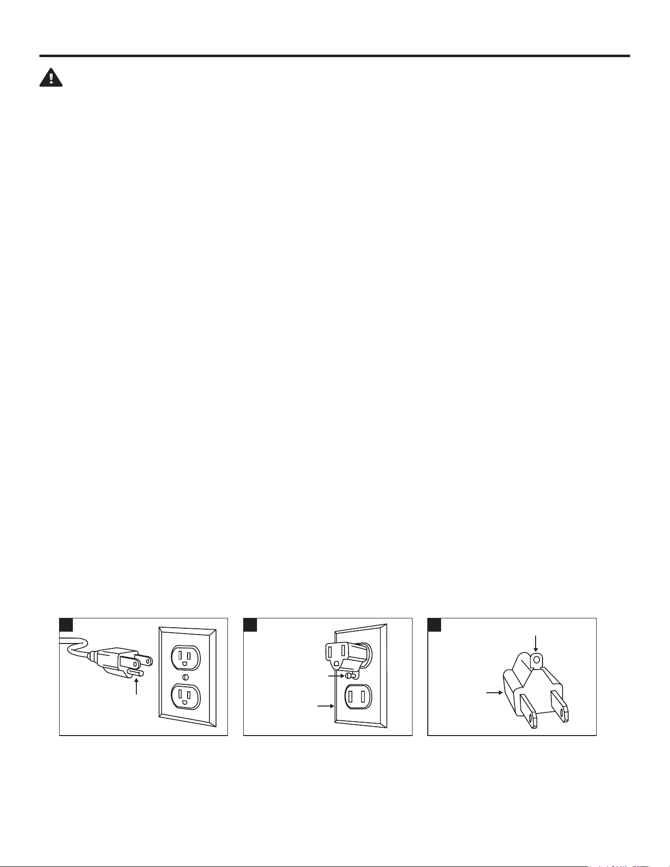
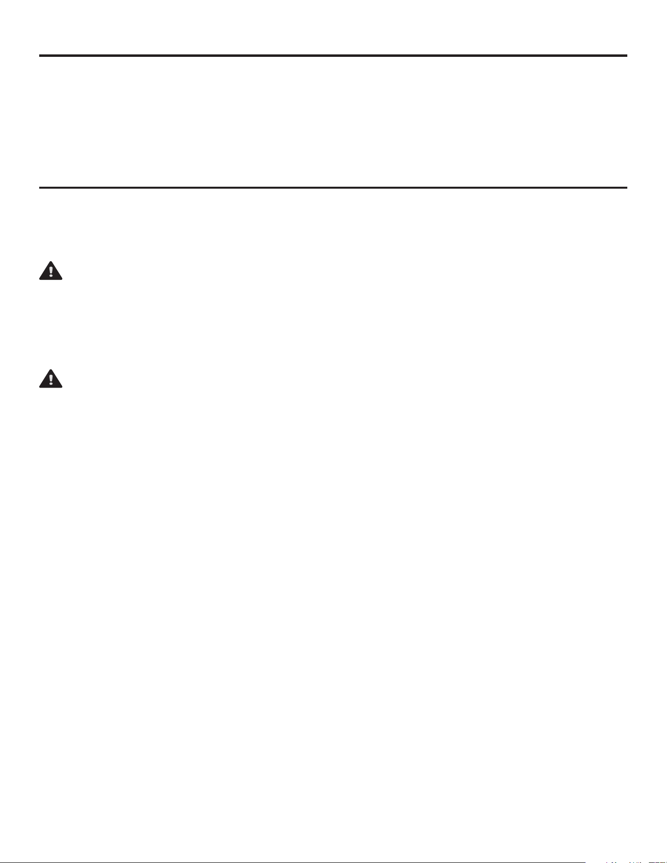
GROUNDING INSTRUCTIONS
• This heater is for use on 120-volt. The cord has a plug as shown below. See illustration or grounding instruction. An
adapter as shown at C is available for connecting three-blade grounding type plugs to two-slot receptacles. The green
grounding plug extending from the adapter must be connected to a permanent ground such as a properly grounded
outlet box. The adapter should not be used if a three-slot grounded receptacle is available.
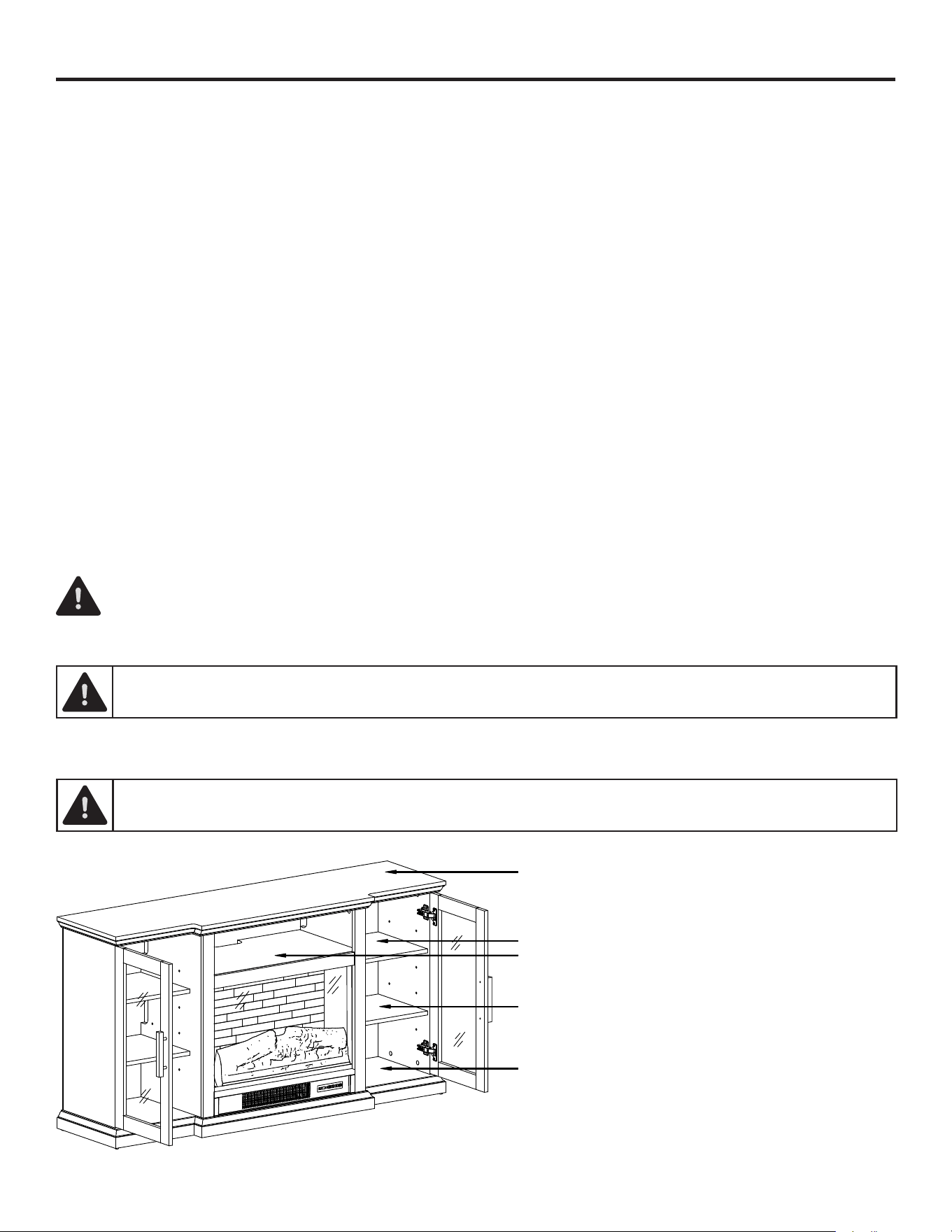
LOCATING YOUR FIREPLACE
When choosing a location for your new replace, ensure the general instructions are followed. Also, for best effect install
the replace out of direct sunlight. It is safe to set the replace insert close to non-combustibles.
SAFETY INFORMATION (CONTINUED)
Grounding Pin
A
Metal Screw
Cover of
Grounding
Box
B
Grounding Means
Adapter
C
4
REMOTE CONTROL
This device complies with Part 15 of the FCC Rules. Operation is subject to the following two conditions: (1) this device may
not cause harmful interference, and (2) this device must accept any interference received, including interference that may
cause undesired operation.
WARNING: Changes or modications to this unit not expressly approved by the party responsible for compliance could void
the user’s authority to operate the equipment.
NOTE: This equipment has been tested and found to comply with the limits for a Class B digital device, pursuant to Part 15
of the FCC Rules. These limits are designed to provide reasonable protection against harmful interference in a residential
installation. This equipment generates, uses and can radiate radio frequency energy and, if not installed and used in
accordance with the instructions, may cause harmful interference to radio communications.
However, there is no guarantee that interference will not occur in a particular installation. If this equipment does cause
harmful interference to radio or television reception, which can be determined by turning the equipment off and on, the user
is encouraged to try to correct the interference by one or more of the following measures:
• Reorient or relocate the receiving antenna.
• Increase the separation between the equipment and receiver.
• Connect the equipment into an outlet on a circuit different from that to which the receiver is connected.
• Consult the dealer or an experienced radio/TV technician for help.
DO NOT mix old and new batteries.
DO NOT use rechargeable silver oxide cell batteries with remote control unit.
DO NOT mix alkaline, standard (Carbon-Zinc), or rechargeable (Nickel-Cadmium) batteries.
DO NOT dispose of batteries in re. Improper disposal may cause batteries to leak or explode.
WARNING: Never attempt to disassemble or alter the product in any way not instructed by this manual.
SAFETY INFORMATION (CONTINUED)
95 lbs (43.1 kg)
20 lbs (9.1 kg)
20 lbs (9.1 kg)
50 lbs (22.7 kg)
50 lbs (22.7 kg)
MAXIMUM WEIGHT CAPACITY
WARNING: Loads heavier than the maximum weights specied may result in instability,
causing tip over resulting in death or serious injury.
F/C
H
5
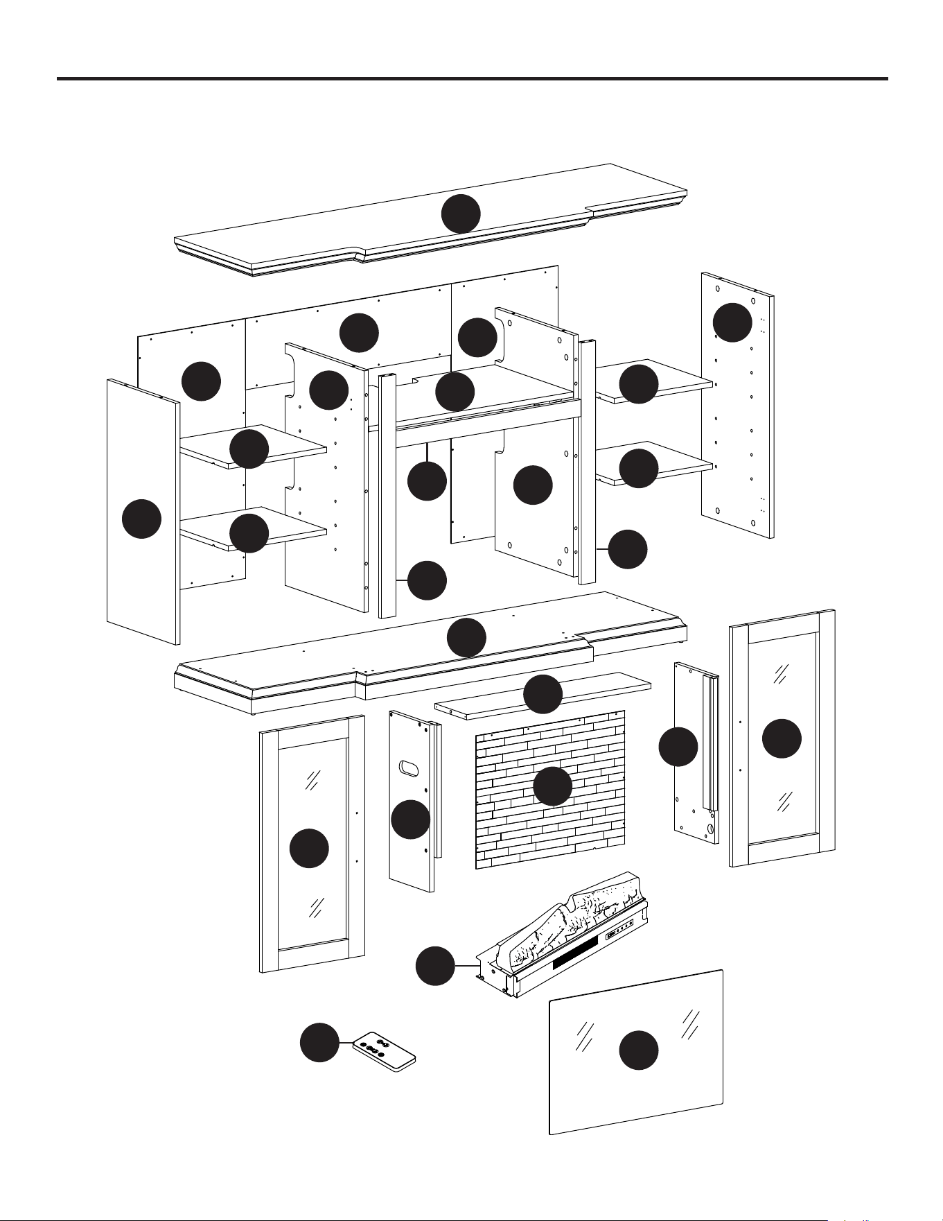
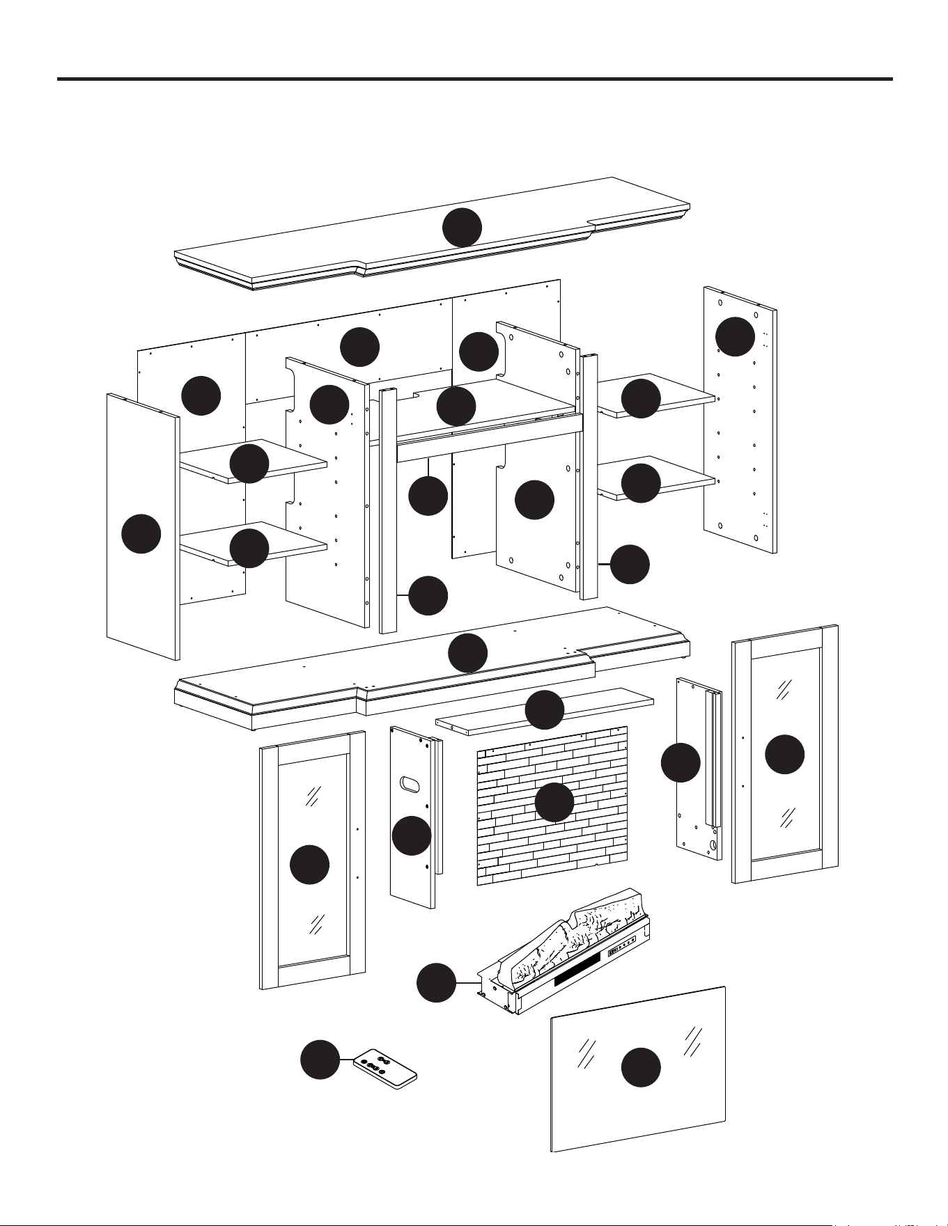
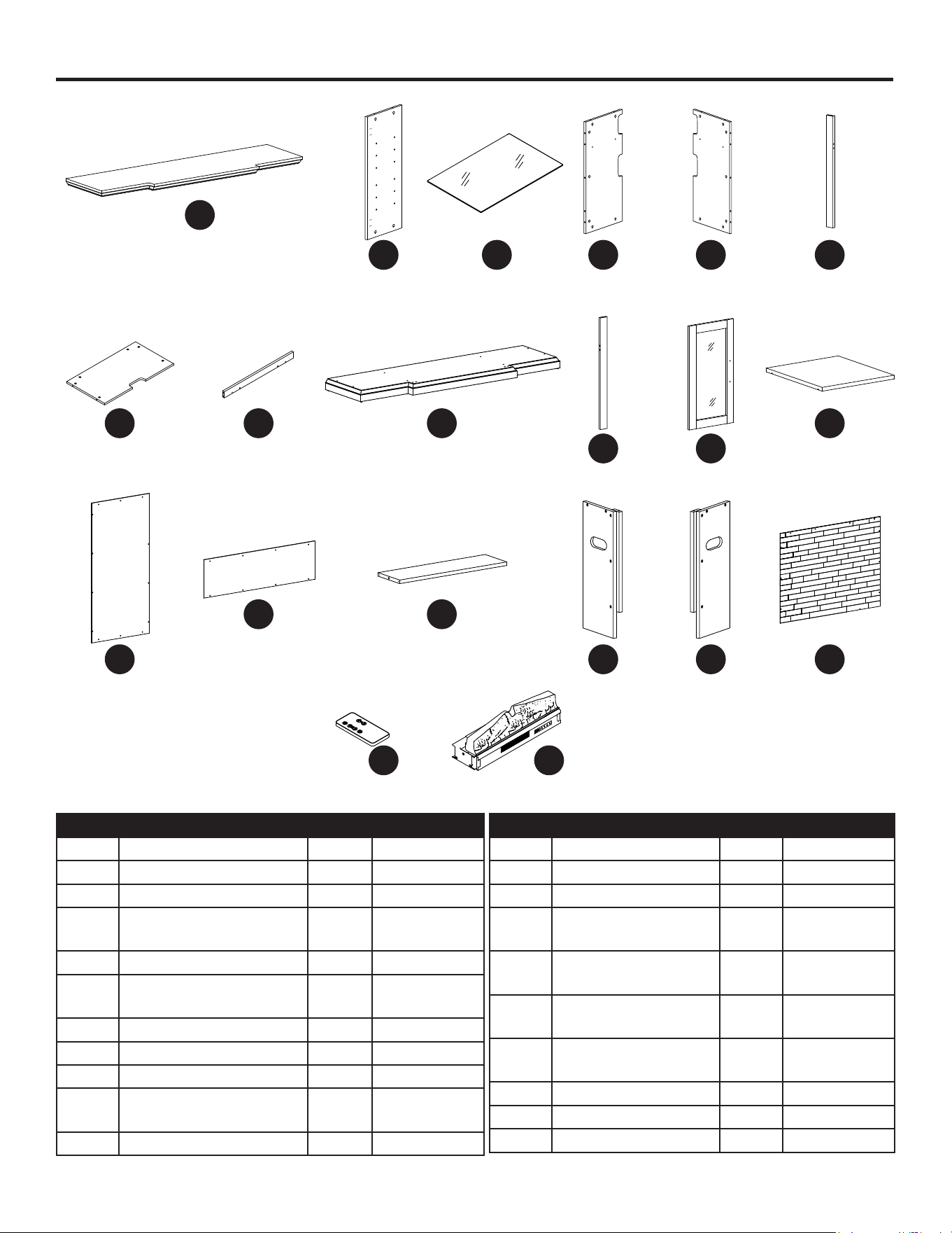
PACKAGE CONTENTS
Carefully remove all pieces from carton and make sure that you have all parts listed.
If you are missing parts, please call GHP customer service at 1-877-447-4768.
A
N
M
B
E
B
L
L
L
L
D
G
H
F
J
I
O
R
P
K
Q
K
BB
C
AA
M
6
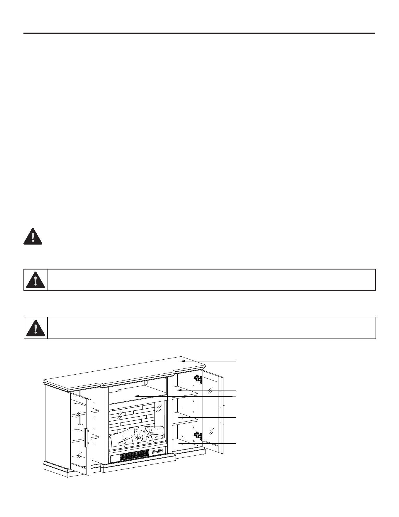
PACKAGE CONTENTS (CONTINUED)
PART DESCRIPTION QTY.
A Top Panel 1
B Side Panels 2
C Glass Panel 1
D Left Partition Panel 1
E Right Partition Panel 1
F Left Middle Molding 1
G Fixed Shelf 1
H Middle Stretcher 1
I Bottom Panel 1
J Right Middle Molding 1
K Door 2
PART DESCRIPTION QTY.
L Adjustable Shelf 4
M Side Back Panel 2
N Middle Back Panel 1
O Support Top Panel 1
P Left Support Panel 1
Q Right Support Panel 1
R Fireplace Back Board 1
AA Remote Control 1
BB Heater 1
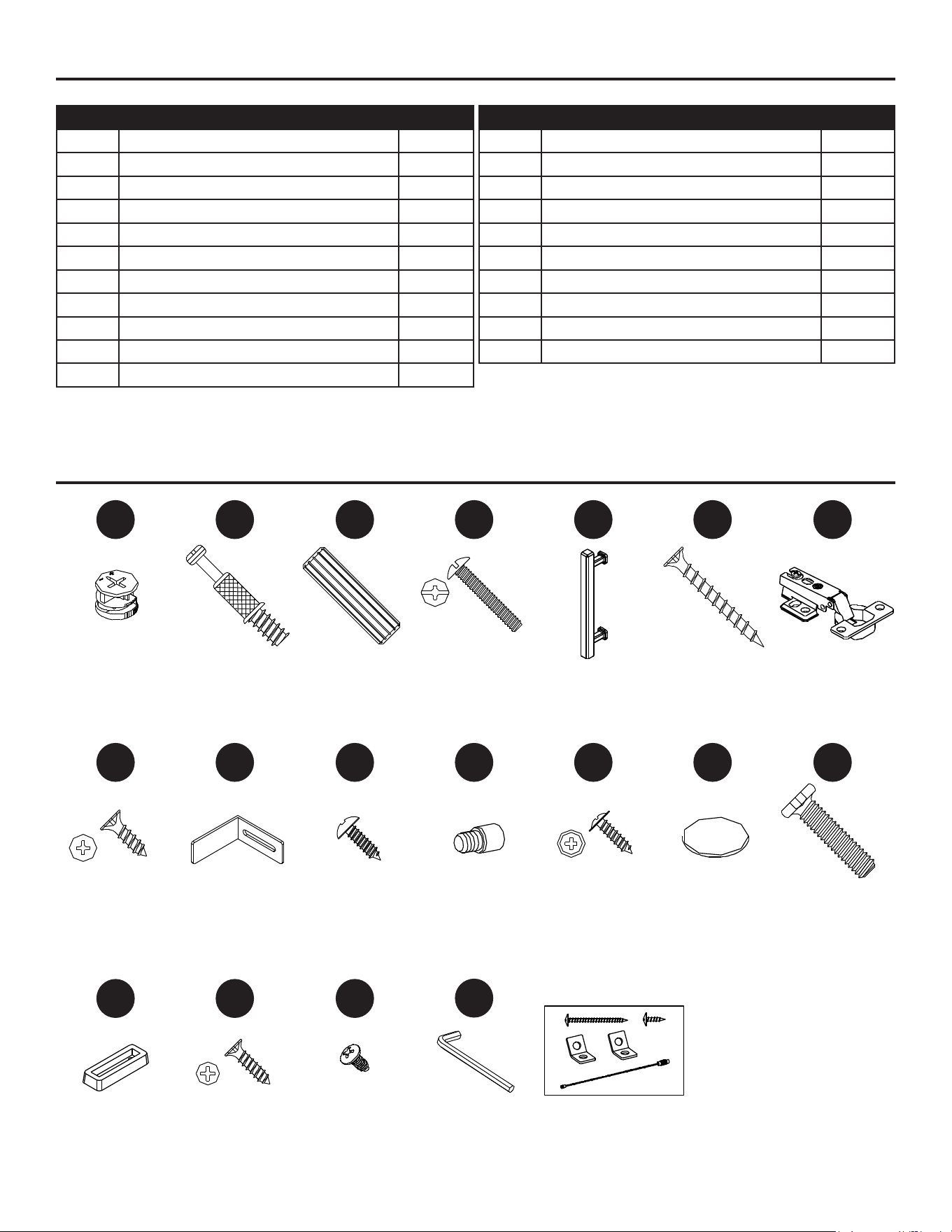
Hardware Kit
HARDWARE CONTENTS
1
8
16
5
12
3
10
18 19
7
15
2
9
17
6
14
4
11
Cam
Lock
Qty. 28
Hinge
Screw
Qty. 24
Door
Stop
Qty. 2
Handle
Qty. 2
Washer Head
Screw
Qty. 46
Wood
Dowel
Qty. 12
Pan Head
Screw
Qty. 2
Short Pan
Head Screw
Qty. 2
Hinges
Qty. 4
Assembly
Bolt
Qty. 6
Cam
Bolt
Qty. 28
Bracket
Qty. 2
Short Flat
Head Screw
Qty. 4
Flat Head
Screw
Qty. 4
Sticker
Cover
Qty. 16
Tipping
Restraint Kit
Qty. 1
Handle
Bolt
Qty. 4
Shelf
Pin
Qty. 16
Hex
Wrench
Qty. 1
Some parts and specications may change without notice.
7
PLANNING ASSEMBLY
Before you begin assembly, locate the instructions and hardware. Compare all parts with the
Hardware Included and Package Contents lists. Be sure you have all the parts and can identify them.
A helping hand is always good. Assemble your mantel with an adult assistant if possible. Some pieces
are heavy and will need to be held by a helper. Assembly time will take approximately 60-90 minutes.
Before assembly, use scissors to unwrap the parts from the packaging. Do not use a box cutter or
exacto-knife, as you may cut into the mantel pieces inside the box and damage the nish. Check
for the hardware bag located inside the packaging. Do not discard any pieces. Use an appropriate
screwdriver to insert and tighten all screws.
Assemble the unit on a carpeted oor or empty carton to avoid any scratches.
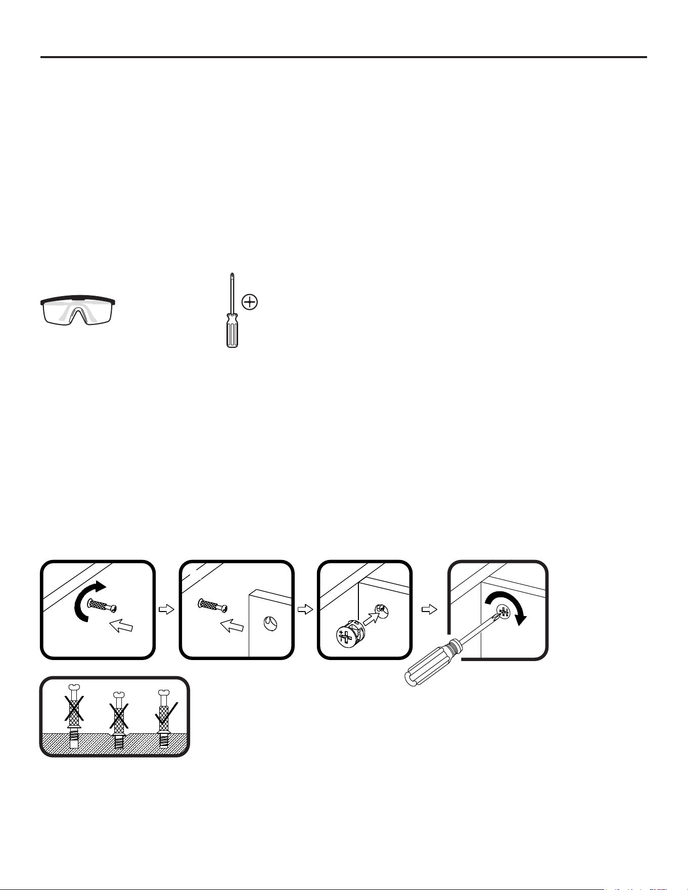
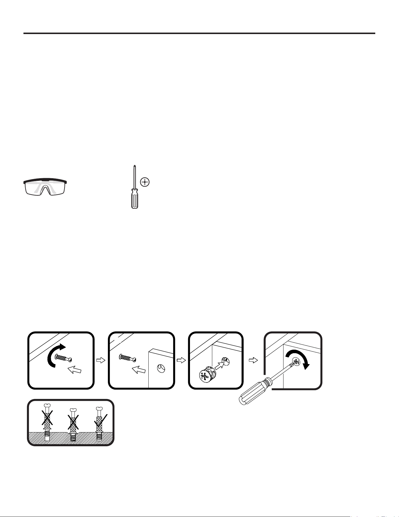
TOOLS REQUIRED
(NOT INCLUDED)
Helpful Tools (not included): soft faced Hammer or Mallet
Safety
Goggles
Phillips
Screwdriver
CAM LOCK ASSEMBLY & OPERATION
1. Screw the Cam Bolt clockwise into the threaded inserts on the panel.
2. Connect both panels together; making sure the Cam Bolt goes into the hole on the end of the
panel for the Cam Lock.
3. Insert the Cam Lock into the pre-drilled large hole on the panel. Make sure the arrow on the face
of the Cam Lock faces out and points towards the Cam Bolt.
4. Take a Phillips Screwdriver and rotate the Cam Lock clockwise to lock the Cam Bolt in place.
1. 2. 3. 4.

8
1
2
3
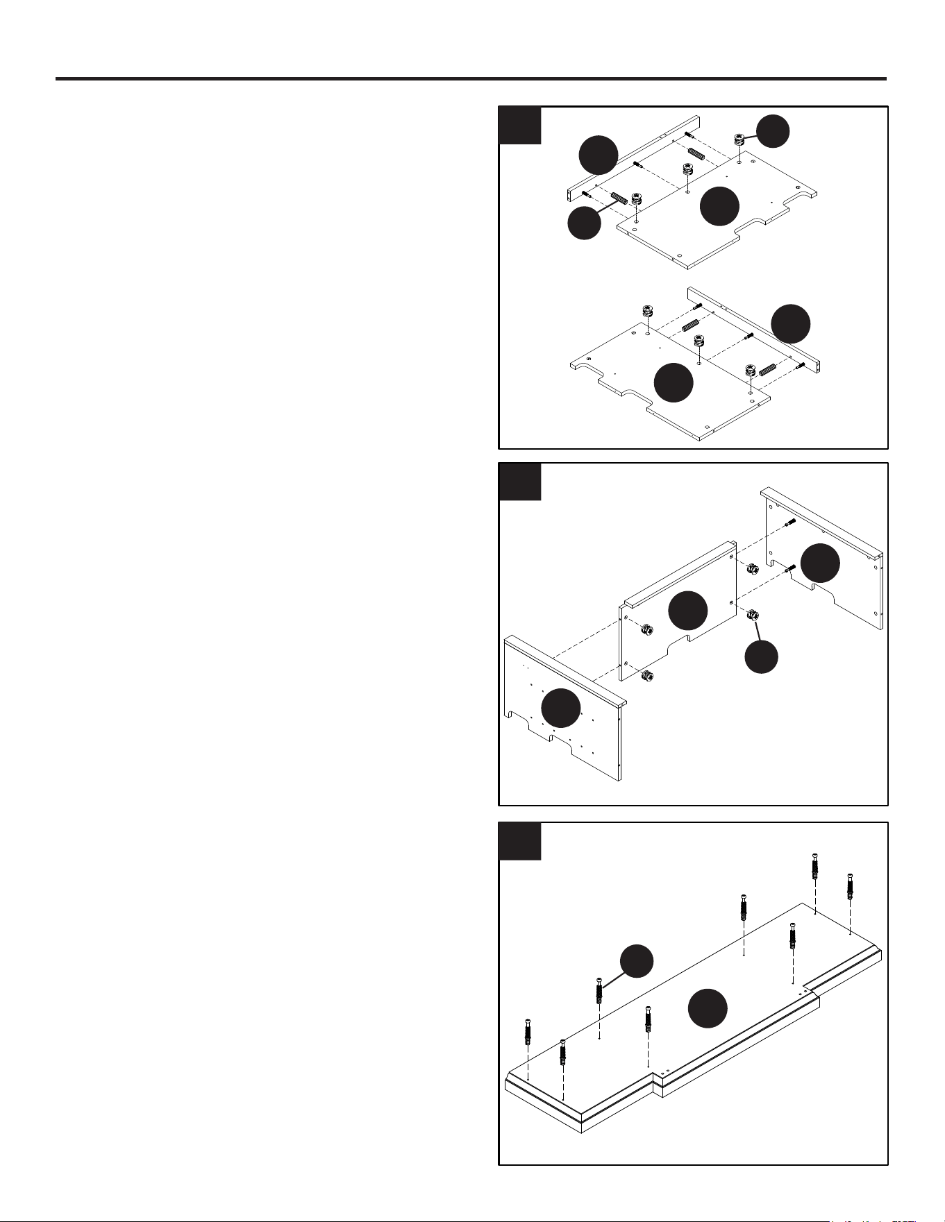
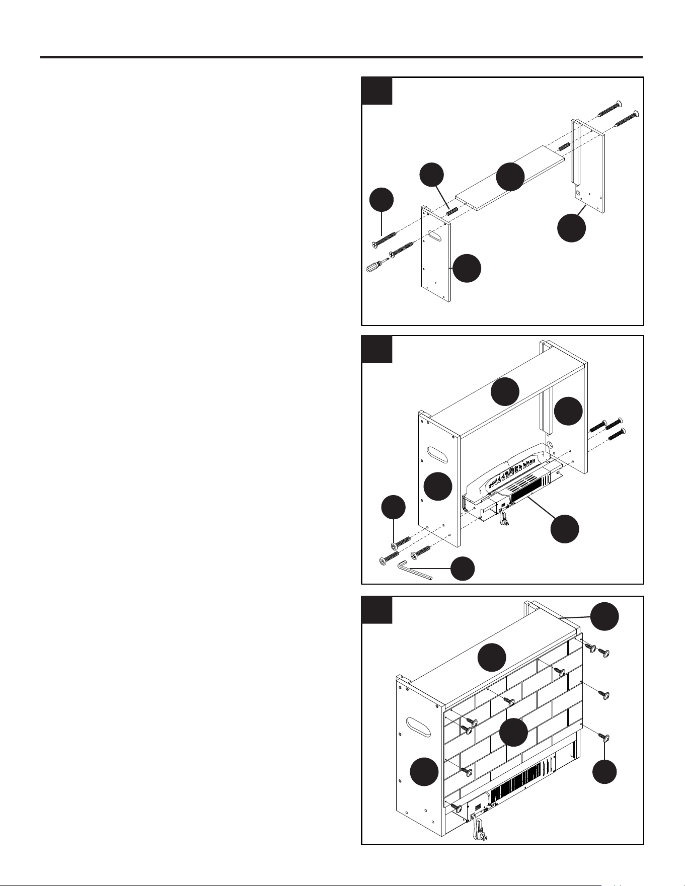
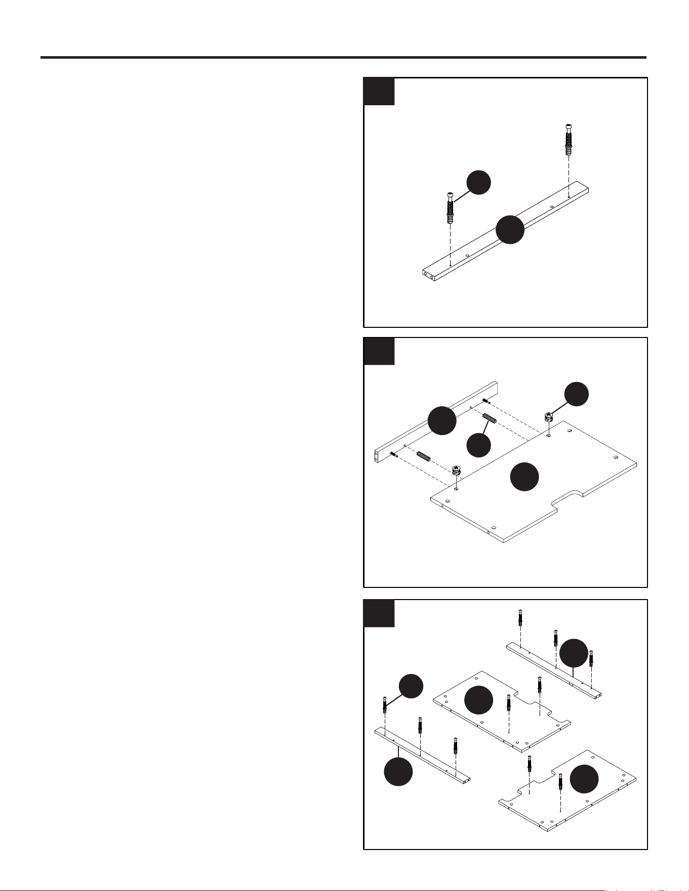
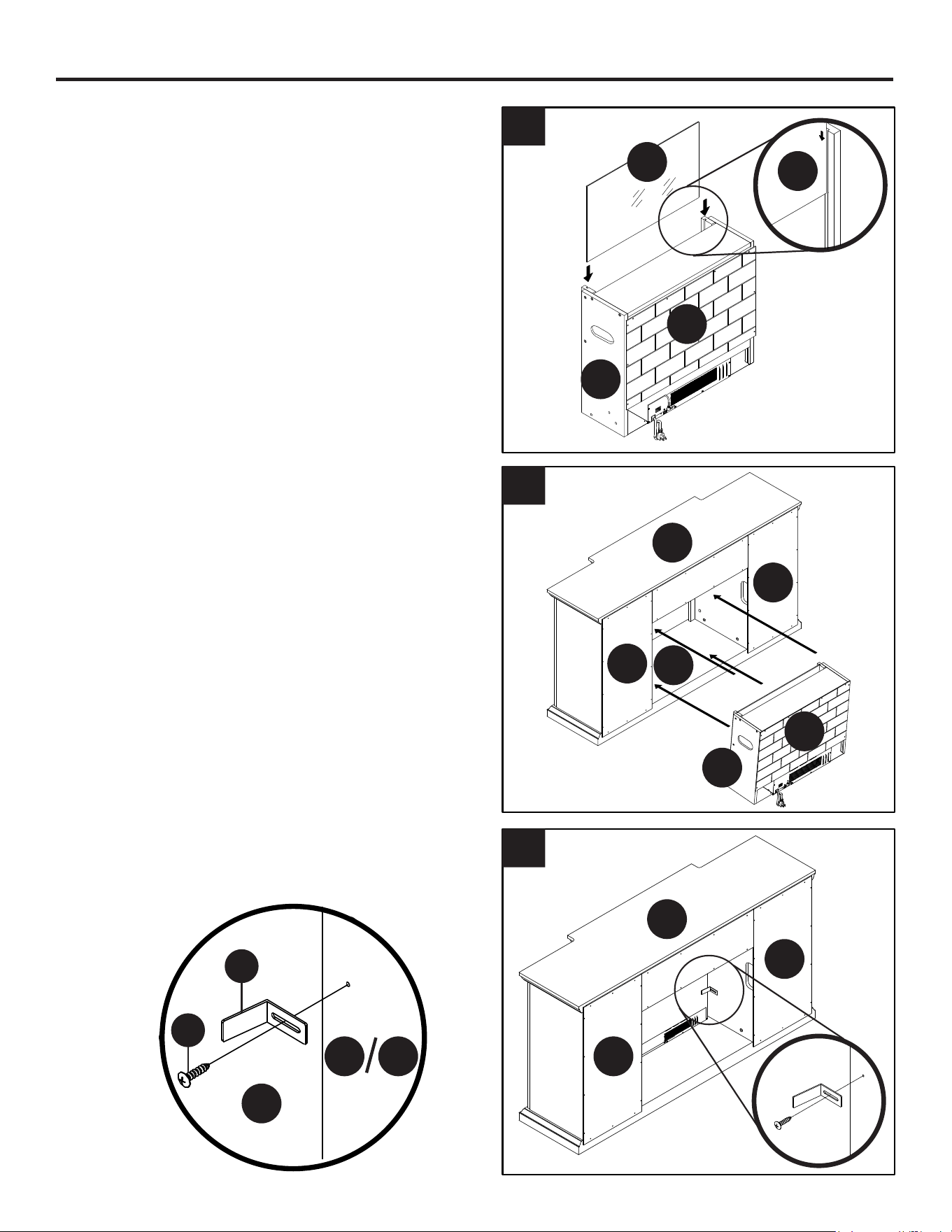
ASSEMBLY INSTRUCTIONS
1. Securely screw two Cam Bolts (2) into the
designated small holes on the Middle Stretcher
(H) using a Phillips screwdriver as shown.
2. Attach the Middle Stretcher (H) to the Fixed
Shelf (G) with two Wood Dowels (3) and two
Cam Locks (1) as shown. Take a screwdriver
and rotate the Cam Lock clockwise to lock the
Cam Bolt in place.
3. Securely screw the Cam Bolts (2) into the
designated small holes on the Partition Panels
(D and E) and the Front Moldings (F and J)
using a Phillips screwdriver as shown.
H
H
G
J
F
D
E
1
3
2
2
9
5
6
ASSEMBLY INSTRUCTIONS (CONTINUED)
4
4. Attach the Left Middle Molding (F) to the Left
Partition Panel (D) with two Wood Dowels (3)
and three Cam Locks (1) as shown. Take a
screwdriver and rotate the Cam Lock clockwise
to lock the Cam Bolt in place.
Attach the Right Middle Molding (J) to the Right
Partition Panel (E) with two Wood Dowels (3)
and three Cam Locks (1) as shown. Take a
screwdriver and rotate the Cam Lock clockwise
to lock the Cam Bolt in place.
5. Attach the Fixed Shelf (G) between the Partition
Panels (D and E) with four Cam Locks (1) as
shown. Take a screwdriver and rotate the Cam
Lock clockwise to lock the Cam Bolt in place.
6. Securely screw eight Cam Bolts (2) into the
designated small holes on the Bottom Panel (I)
using a Phillips screwdriver as shown.
D
D
E
G
F
J
E
1
1
3
I
2
10
8
9
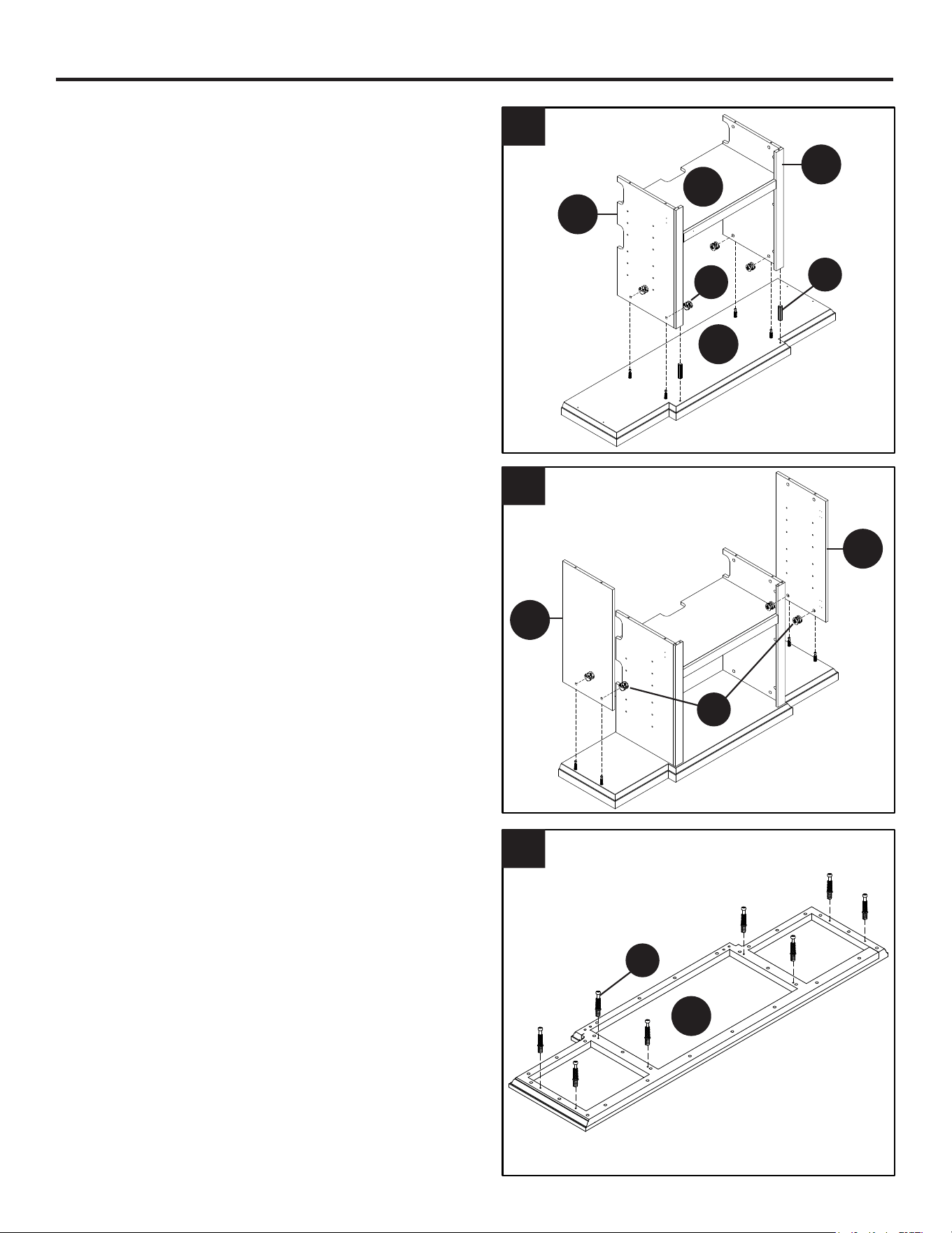
ASSEMBLY INSTRUCTIONS (CONTINUED)
7
7. Attach the Partition Panels Assembly to the
Bottom Panel (I) with two Wood Dowels (3)
and four Cam Locks (1) as shown. Take a
screwdriver and rotate the Cam Lock clockwise
to lock the Cam Bolt in place.
8. Attach the Side Panels (B) to the Bottom Panel
(I) with four Cam Locks (1) as shown. Take a
screwdriver and rotate the Cam Lock clockwise
to lock the Cam Bolt in place.
9. Securely screw eight Cam Bolts (2) into the
designated small holes on the Top Panel (A)
using a Phillips screwdriver as shown.
I
D
B
A
B
G
E
3
2
1
1
11
11
12
ASSEMBLY INSTRUCTIONS (CONTINUED)
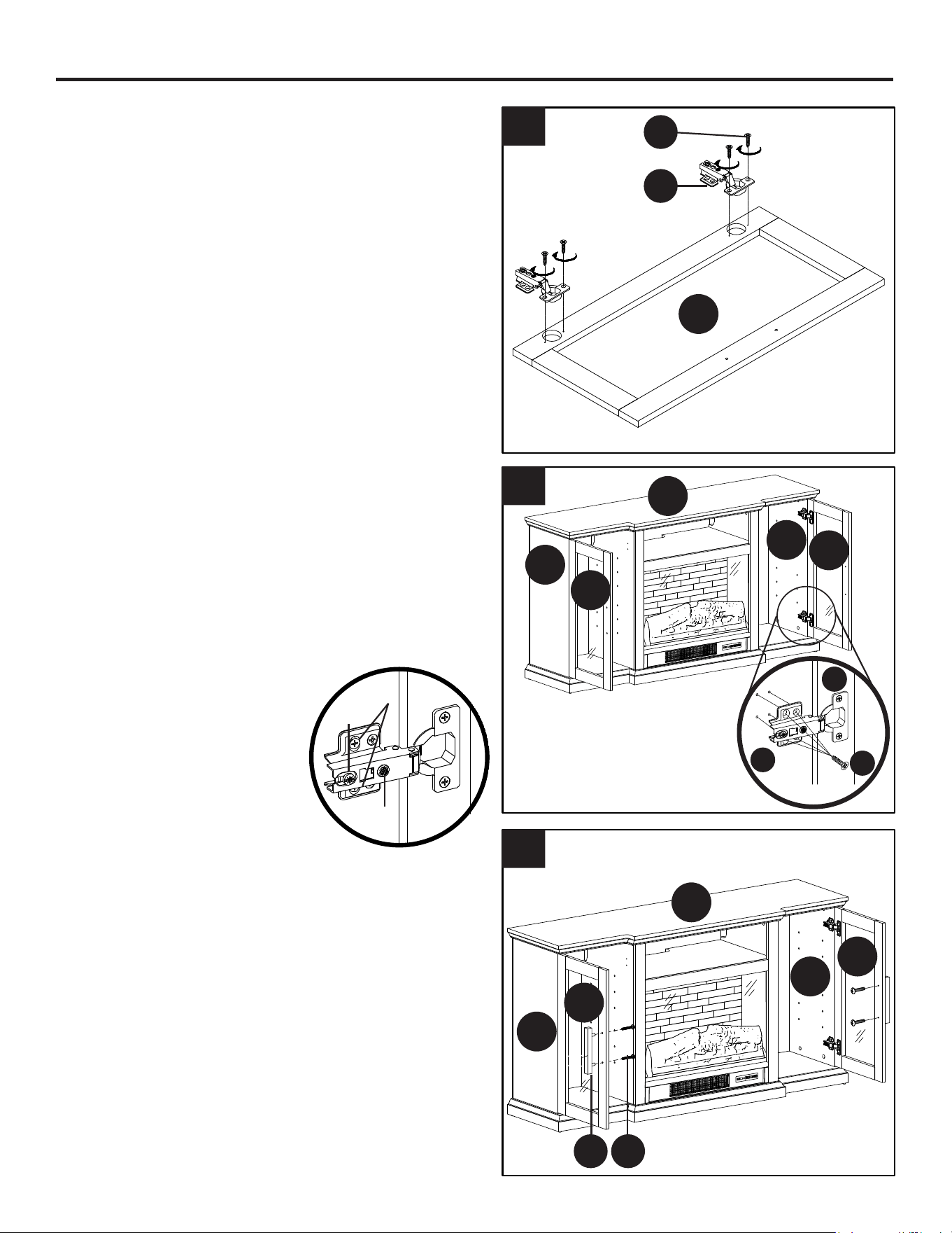
10
10. Attach the Top Panel (A) to the assembled unit
with two Wood Dowels (3) and eight Cam Locks
(1) as shown. Take a screwdriver and rotate
the Cam Lock clockwise to lock the Cam Bolt in
place.
Now, go back and securely tighten all the cam
locks and screws. Make sure that all the parts
are tight and there are no gaps between the
parts. This will help keep the unit square.
11. NOTE: Before attaching
the back panels be sure
that the unit is at 90°.
NOTE: We recommend attaching back panel
with washer head screws at the four corners
rst.
Pick up the Middle Back Panel (N) and align the
pre-drilled holes against the upper long edge
with the pilot holes on the back of Top Panel
(A). Fasten it in place with the provided Washer
Head Screws (12). Using the pilot holes as a
guide, align and attach Side back panels (M)
using Washer Head Screws (12) as shown.
12. Combine the Ember Log with the Heater (BB)
together using provided Screws (18).
A
A
M
M
N
B
B
G
3
1
12
18
18
90˚
12
14
15
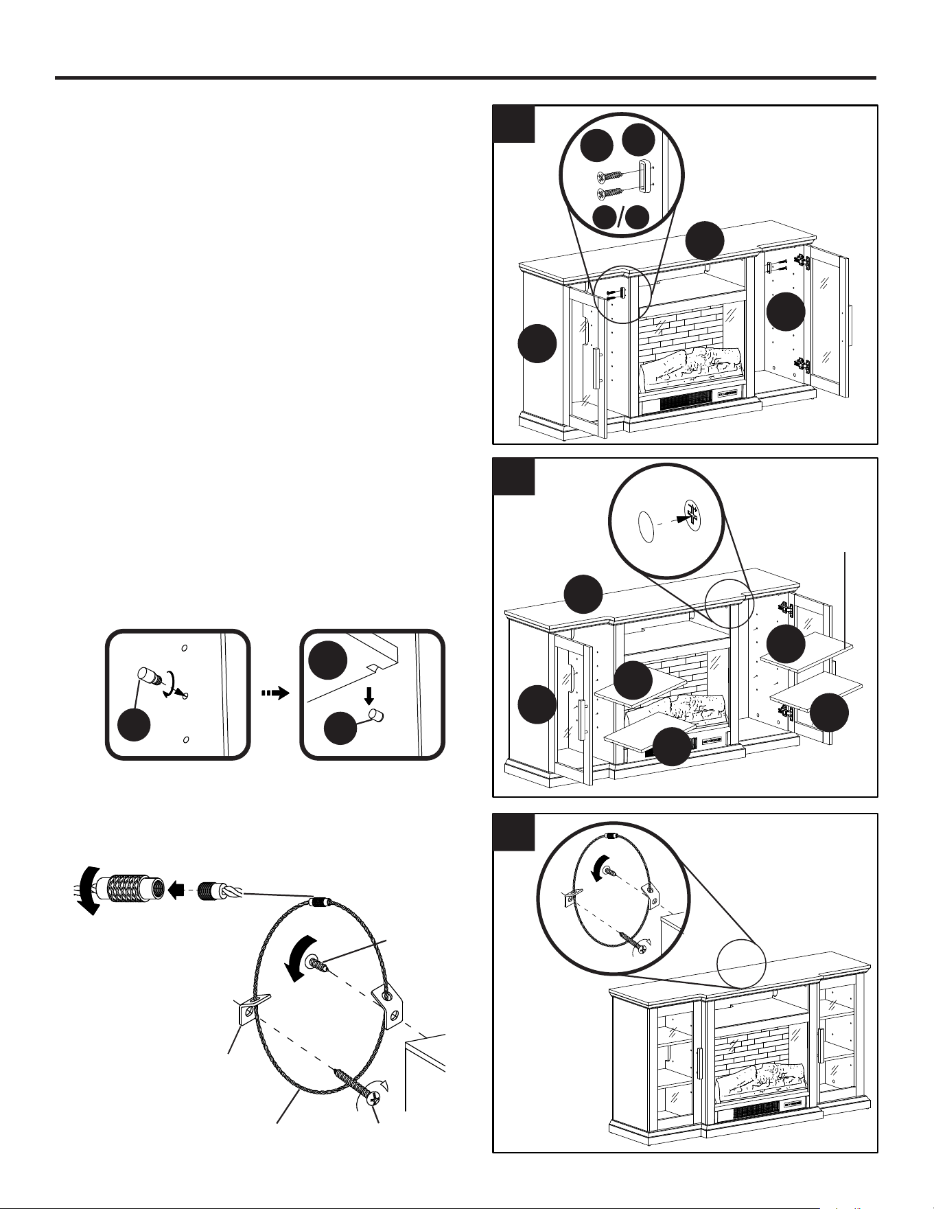
ASSEMBLY INSTRUCTIONS (CONTINUED)
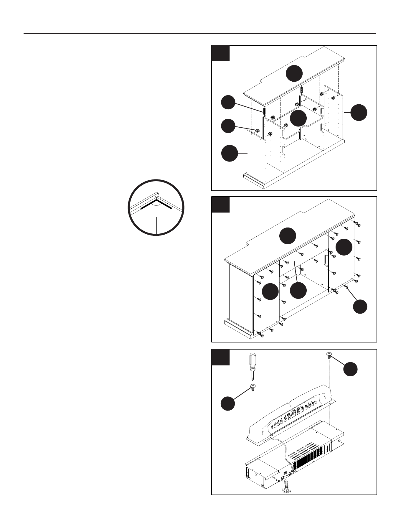
13
13. Attach the Support Top Panel (O) between
the Support Panels (D and E) with two Wood
Dowels (3) and four Screws (6) as shown.
14. Using the Hex Wrench (19) fasten the Support
Panels (P and Q) to the Heater (BB) with six
Bolts (15) as shown.
15. Using the pilot holes as a guide, attach the
Fireplace Back Panel (R) to the Support Panels
(P and Q) with provided Washer Head Screws
(12).
O
Q
P
6
15
19
3
O
BB
P
Q
R
O
P
Q 12

13
17
18
ASSEMBLY INSTRUCTIONS (CONTINUED)
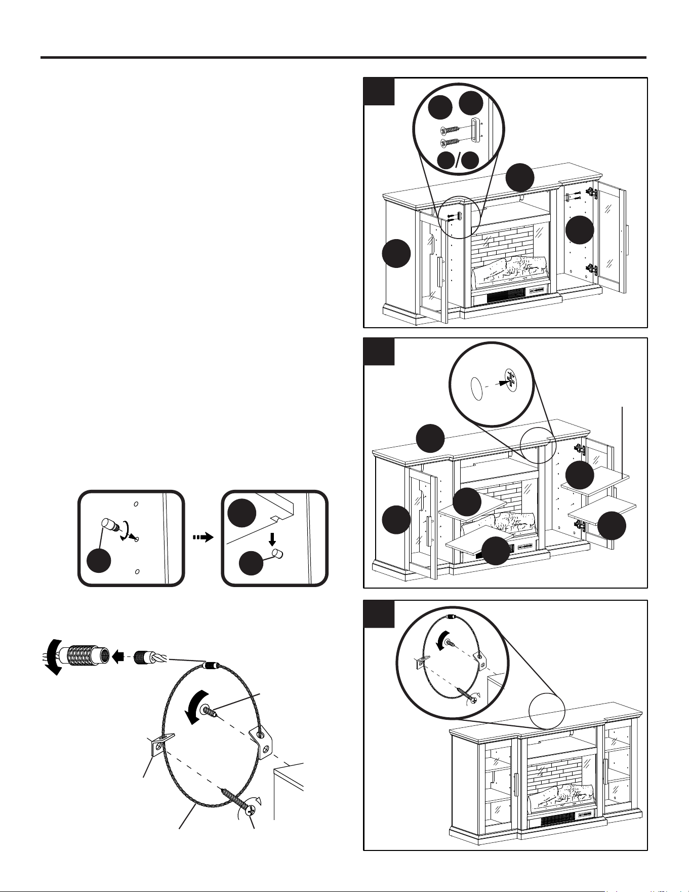
16
16. Slide the Glass Panel (C) into the grooves
between the Support Panels (P and Q) and fully
insert into the Heater (BB).
17. Tilt and rest the Heater assembly onto the
Bottom Panel (I) and gently push into place.
18. Using the pilot holes as a guide, attach Large
Metal Brackets (9) to the Partition Panels (D
and E) with the Pan Head Screws (10) as
shown.
R
D E
R
Q
C
C
M
M
I
R
Q
9
10
A
A
M
M

14
F/C
H
F/C
H
20
21
ASSEMBLY INSTRUCTIONS (CONTINUED)
19
19. Extend two Hinges (7) and rest the hinge cups
onto the cutouts of each Doors (K). Secure the
door hinges in place with the Wood Screws (8).
20. Pick up the Door (K) and fasten the Hinge
Bases (7) onto the Side Panel (B) with four
Wood Screws (8) in each hinge.
Adjust the hinges as required to align the door
to the cabinet. Loosen the screw slightly and
adjust the hinge position and then re-tighten
the screw(s) on the hinge to lock in the new
position.
1. This screw adjusts the
forward and backward
alignment.
2. This screw adjusts the
right to left alignment.
3. These screws adjust
the up and down
alignment.
21. Attach one Handle (5) to the front side of each
door with two Handle Bolts (4).
K
8
7
5 4
x2
2
3
1
F/C
H
A
B
K
K
K
8
B
B
A
K
K
B
B
15
24. Use the instructions printed on the Anti-tip
Hardware to secure the unit to the wall.
F/C
H
F/C
H
23
24
ASSEMBLY INSTRUCTIONS (CONTINUED)
22
22. With the pilot holes as a guide, fasten the Door
Stopper (16) to the Partition Panels (D and E)
using two Wood Screws (17).
23. Cover cam lock holes and bolt holes with the
Sticker Covers (14) as shown.
Screw sixteen Shelf Supports (11) into the holes
at the desired height inside each compartment,
ensuring they are level. Tilt and rest the
Adjustable Shelves (L) onto the Shelf Supports
(11) nished side forward.
Short
Screw
Connector
Steel
Cable
Long
Screw
Metal
Bracket
WALL
TV
STAND
F/C
H
A
B
L
B
F/C
H
F/C
H
F/C
H
11
11
A
B
L
L
L
L
F/C
H
F/C
H
F/C
H
17
16
D E
Finished
Side

16
OPERATING INSTRUCTIONS
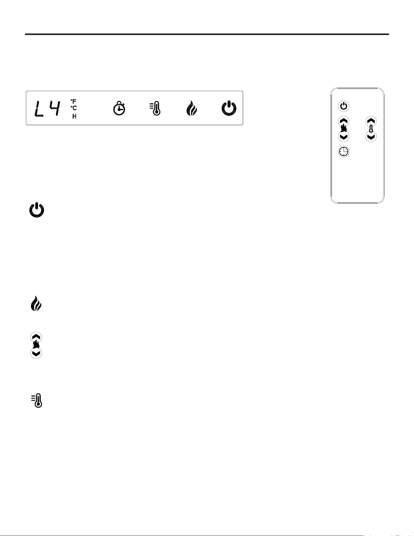
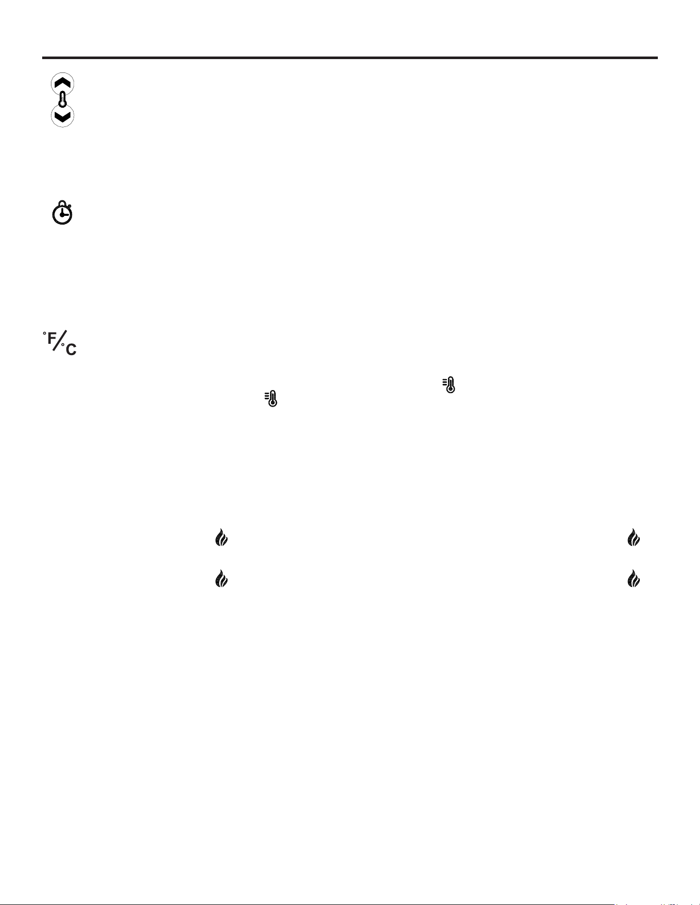
HEATER DEFAULT SETTING
The default factory setting for your thermostat is 86 Degrees Fahrenheit. If your room temperature is already 86 Degrees
Fahrenheit or above, then your heater will shut OFF after about 3 minutes. See Heater directions for how to adjust the
temperature settings in order to keep your heater ON until your desired room temperature is reached.
CONTROLS AND DISPLAY
The control panel will display L4 when the unit is rst plugged in and powered ON. The unit will
only detect the ambient temperature after the fan and heater have been ON for 3 minutes. As
long as the unit remains plugged in, the control panel will display the previous settings. Whichever
control icon you press will display the current setting of the corresponding function. Press the
control icon again to adjust the setting. Following adjustment of any setting(s), the unit will resume
to display the heater setting after 5 seconds.
POWER FUNCTION
• Press the POWER ICON to turn on the main power to the unit ON or OFF.
• When the power is turned ON, the display panel will show the previous Heater setting, the display panel will show the
previous ame brightness level if the heater was off.
• When the power is turned OFF, the ame light goes out immediately, and the log light slowly dims for 2 seconds until it
is completely off.
• Memory function: When this button is turned off, the unit will automatically remember the current function status, and
when it is turned on again, it will return to the state before the last shutdown.
• Special note: If the power cord is unplugged and then plugged in again, the insert will automatically revert to the default
ame L4 and Heater Off.
FLAME FUNCTION (main control)
• Press the FLAME ICON to display the current ame brightness setting
• Press the FLAME ICON again to cycle through the ame brightness settings: L4, L3, L2, and L1.
FLAME FUNCTION (remote control)
• Press the FLAME UP ICON to display the current ame brightness setting and again to increase the Brightness level.
• Press the FLAME DOWN ICON to display the current ame brightness setting and again to decrease the Brightness
level.
HEATER FUNCTION (main control)
• Press the HEATER ICON to display the current heater setting.
• Press the HEATER ICON again to scroll down through the heater settings.
• Set the heater to “ON” (High) to have the heater run continually. If the heater detects a temperature over 86°F or 30°C
the heater will turn off until the temperature goes below these values.
• Set the heater to “OF” (OFF) to use the ame functions without heat.
• Set the heater to “FA” (Fan Mode), to use the fan function without heat.
• This heater has a thermostat sensor to control the ambient temperature in the surrounding area of the replace. The
heater will cycle ON and OFF to maintain the selected temperature.
• The thermostat setting range is 86°F, 84°F, 82°F, 80°F, 78°F, 76°F, 74°F, 72°F, 70°F, 68°F, 66°F, 64°F, 62°F (30°C, 29°C,
28°C, 27°C, 26°C, 25°C, 24°C, 23°C, 22°C, 21°C, 20°C, 19°C, 18°C, 17°C).
Note: This may not exactly match the room thermostat reading as their sensors are located in different areas.
Figure 1
Figure 2
17
OPERATING INSTRUCTIONS (CONTINUED)
TIMER FUNCTION (main control)
• The TIMER function will set a countdown to shut down the unit’s main power.
• Press the TIMER ICON to display the current Sleep Timer setting.
• Press the TIMER ICON again to cycle through the timer settings which are: 10 (minutes), 20 (minutes), 30
(minutes), 40 (minutes), 50 (minutes), 1H, 2H, 3H, 4H, 5H, 6H, OF (OFF).
• When the timer reaches zero, it will turn OFF the main power and will maintain all the settings in memory.
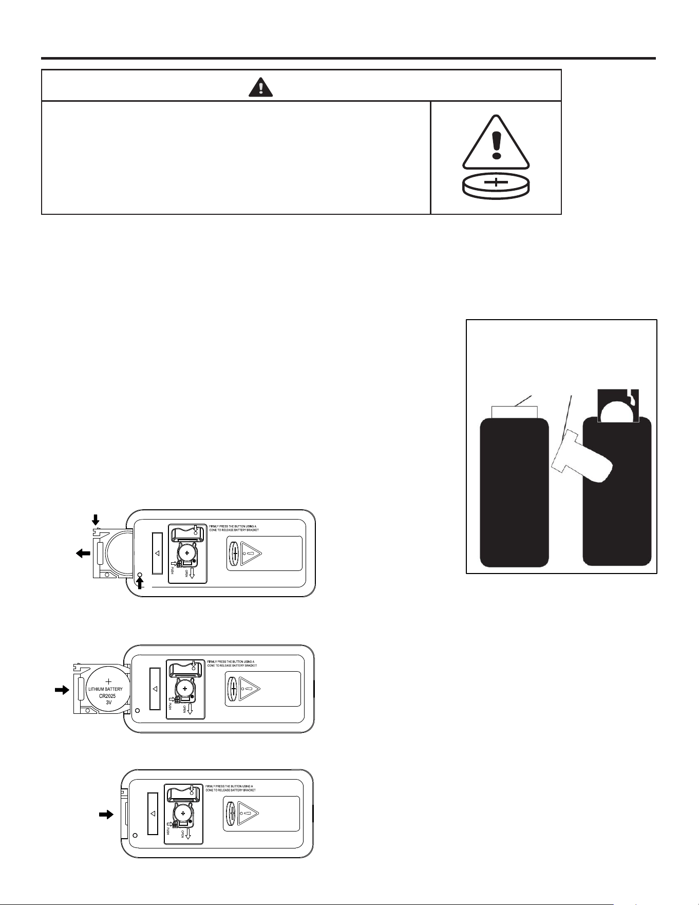
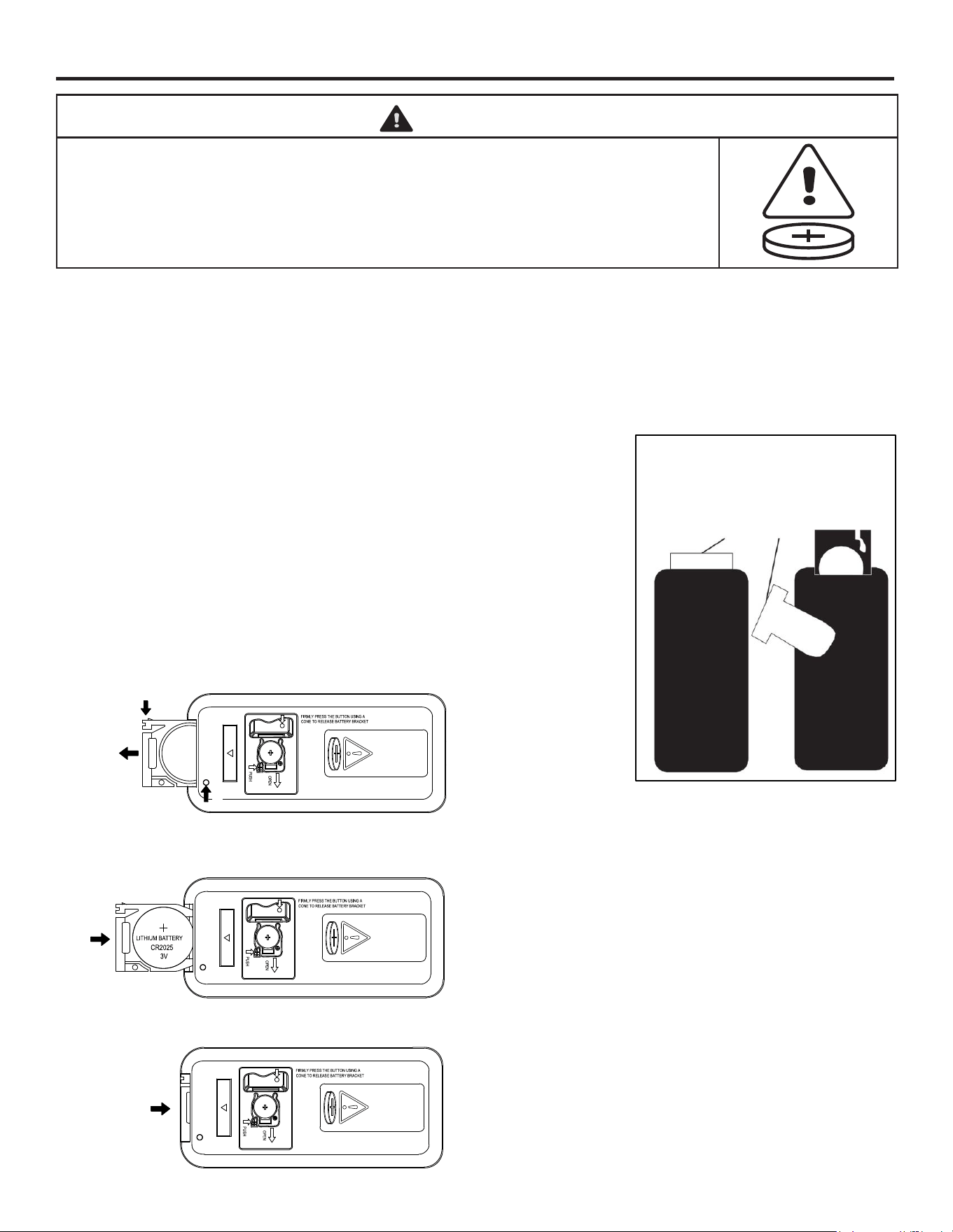
BATTERY SAFETY
• Remove and immediately recycle or dispose of used batteries according to local regulations and keep away from
children. Do NOT dispose of batteries in household trash or incinerate.
• Even used batteries may cause severe injury or death.
• Call a local poison control center for treatment information.
• Battery type CR2025
• Nominal battery voltage 3V
• Non-rechargeable batteries are not to be recharged.
• Do not force discharge, recharge, disassemble, heat above 60°C (140 °F) or incinerate. Doing so may result in
injury due to venting, leakage or explosion resulting in chemical burns.
• Ensure the batteries are installed correctly according to polarity (+ and -).
• Do not mix old and new batteries, different brands or types of batteries, such as alkaline, carbon-zinc, or
rechargeable batteries.
• Remove and immediately recycle or dispose of batteries from equipment not used for an extended period of time
according to local regulations.
• Always completely secure the battery compartment. If the battery compartment does not close securely, stop using
the product, remove the batteries, and keep them away from children
FAHRENHEIT TO CELSIUS
Note: This can only be set from the control panel and will not work if using the remote control.
• With the heater on, press and release the HEATER ICON once, then press and hold the HEATER ICON
for ve seconds to change the temperature scale. Repeat the same process to convert back to the original scale.
HEATER DISABLE
The power to the heater can be disengaged to prevent the heater from being accidentally or unintentionally powered
on. This feature is primarily added to help prevent children from powering on the heater when it is not desired.
Note: The heater override can only be set from the control panel and will not work if using the remote control.
• Press the FLAME ICON once, then press and HOLD the FLAME ICON again for 5 seconds to enter
HEATER DISABLE mode.
The temperature display ashes several times to indicate that the heater function is disabled.
• Press the FLAME ICON once, then press and HOLD the FLAME ICON again for 5 seconds again to exit
HEATER DISABLE mode.
HEATER FUNCTION (remote control)
• Press the HEATER UP ICON to display the current heater setting and again to increase the Temperature.
• Press the HEATER DOWN ICON to display the current heater setting and again to decrease the Temperature.
NOTE: BATTERY DISPOSAL
Please always dispose of batteries at a suitable recycling point.
18
OPERATING INSTRUCTIONS (CONTINUED)
WARNING
• INGESTION HAZARD: This product contains a button cell or coin
battery.
• DEATH or serious injury can occur if ingested.
• A swallowed button cell or coin battery can cause Internal Chemical
Burns in as little as 2 hours.
• KEEP new and used batteries OUT OF REACH of CHILDREN.
• Seek immediate medical attention if a battery is suspected to be
swallowed or inserted inside any part of the body.
REMOTE CONTROL INITIAL SETUP
The infrared remote control relies on a line of sight and must be pointed at the ame/screen of the replace to work.
The remote control unit has the controls required to turn ON/OFF both the main power and the heater.
If you prefer to use the control panel on the replace unit itself, the layout of the buttons on control panel and remote
control unit can be seen in Figures 1 and 2, respectively.
1. Plug your replace into a 15-amp, 120-volt power outlet.
2. Turn the power on. Flame will show on the back screen of the replace.
3. Remove plastic tab from inside battery compartment to activate remote
control. See gure 3.
4. Point the remote control directly at the replace ame/screen and use
the buttons to operate the replace.
BATTERY REPLACEMENT PROCEDURE (Size CR2025)
For replacement battery, use a lithium-based CR2025 battery.
Please follow the sequence below to replace the battery.
Press the button using a pin to release the battery bracket.
Then push the bottom lever in and slide out the bracket.
Figure 3
The plastic tab inside the battery
compartment MUST be removed
before the remote control
will operate.
(Pull tab)
1
2
3
SLIDE
PUSH
PRESS
Insert the battery with the button side into the battery bracket, making sure the battery is rmly seated.
Press the battery bracket into the remote control, making sure it snaps into position.
19
CARE AND CLEANING
The motors used on the fan and the ame generator assembly are pre-lubricated for extended bearing life and require no
further lubrication. However, periodic cleaning/vacuuming of the fan/heating unit is recommended. Make sure the unit is
turned OFF and unplugged whenever you are cleaning the heater of the replace.
WARNING
Make sure the power is turned off before proceeding. Any electrical repairs or rewiring of this unit should be carried out
by a licensed electrician in accordance with national and local codes. If repairing or replacing any electrical component or
wiring, the original wire routing, color coding and securing locations must be followed.
Clean the metal trim using a soft cloth, slightly dampened with citrus oil based product and buff with a clean soft cloth. DO
NOT use brass polish or household cleaners as these products will damage the metal trim. Citrus oil based products can
be obtained at supermarkets or hardware stores.
WARNING
During any service of this appliance, the power to the unit must be turned off. Always remember to remove the electrical
plug from the wall outlet.
WARNING
Disconnect power before attempting any maintenance or cleaning to reduce the risk of re, electrical shock, or personal
injury.
WARNING
Do not use this replace if any part of it has been under water. Immediately call a qualied service technician to inspect
the replace and replace any part of the electrical system.
WARNING
Electric outlet wiring must comply with local building codes and other applicable regulations to reduce the risk of re,
electric shock and injury to persons
20
TROUBLESHOOTING
PROBLEM POSSIBLE CAUSE CORRECTIVE ACTION
Fireplace does not
operate; the log set and
ame effect are not lit.
1. The replace is not plugged in.
2. A circuit breaker is tripped or a
fuse has blown.
3. Defective controls.
4. Loose wiring.
1. Make sure the replace is plugged in to a
standard 120V outlet.
2. Check additional appliances on the circuit;
ideally the replace should be on a
dedicated 15-amp circuit.
3. Call customer service: 1-877-447-4768.
4. Call customer service: 1-877-447-4768.
Excessive noise when
the ame is ON but the
heater OFF.
1. Rotating ame reector shaft rubbing
against housing.
2. Defective ame reector shaft motor.
1. Open back of rebox and reposition ame
reector shaft. Unplug or turn off power to
the unit prior to servicing.
2. Call customer service: 1-877-447-4768.
Heater is not operating. 1. Incorrect operation.
2. Defective heater switch.
3. Defective heater assembly.
4. Loose wiring.
5. Dirty or clogged sliding door.
6. Thermostat has been satised.
1. Refer to operating instructions.
2. Call customer service: 1-877-447-4768.
3. Call customer service: 1-877-447-4768.
4. Call customer service: 1-877-447-4768.
5. Unplug the unit. Clear door area of dust
and debris. Wait ve minutes, plug the unit
in again and turn on the heater.
6. Increase desired room temperature on the
control panel/remote.
Excessive noise when
the heater is operating.
1. Dirty or clogged blower.
2. Defective heater assembly.
1. Refer to “Maintenance of Motors” in the
Maintenance section of this manual.
2. Call customer service: 1-877-447-4768.
If you have any questions regarding the product, please call customer service at
1-877-447-4768 8:00 a.m. – 4:30 p.m. CST, Monday – Friday.
21
REPLACEMENT PARTS
PART DESCRIPTION QTY. 237-807-359
A Top Panel 1 20-01-385
B Side Panels 2 20-01-387
C Glass Panel 1 20-01-403
D Left Partition Panel 1 20-01-388
E Right Partition Panel 1 20-01-389
F Left Middle Molding 1 20-01-390
G Fixed Shelf 1 20-01-391
H Middle Stretcher 1 20-01-392
I Bottom Panel 1 20-01-393
J Right Middle Molding 1 20-01-394
K Door 2 20-01-395
PART DESCRIPTION QTY. 237-807-359
L Adjustable Shelf 4 20-01-396
M Side Back Panel 2 20-01-397
N Middle Back Panel 1 20-01-398
O Support Top Panel 1 20-01-399
P Left Support Panel 1 20-01-400
Q Right Support Panel 1 20-01-401
R Fireplace Back Board 1 20-01-402
AA Remote Control 1 20-01-404
BB Heater 1 20-01-405
Hardware Kit 20-01-406
A
B
G
M P Q R
N
AA BB
O
H I L
J H
C D E F
22
SERVICE PARTS
PART DESCRIPTION 237-807-359
1 Power cord 23IHLA.D.9
2 Motor 23IHLA.D.1
3 Control PCBA S03-23CA.D.4
4 Flame PCBA S03-18CM.D.2
5 Log set S03-23CA.S.2
6 Control box 26C2D.S.1
7 Fan heater 23IHLA.D.2
8 Log set PCBA S03-23CA.D.10
9 Flame Reector S03-23CA.G.3
10 Main PCBA S03-23CA.D.1B
11 Log set cable S03-23CA.D.9
10
11
9
8
7
4
5
6
3
2
1
23
GHP Group, Inc.
1501 Nicholas Blvd., Elk Grove Village, IL 60007
ONE YEAR LIMITED WARRANTY
If within one year from the date of original purchase, this item fails due to a defect in material or
workmanship, we will replace or repair at our option, free of charge. To order parts or obtain warranty
service, call 1-877-447-4768, 8:00 a.m. – 4:30 p.m. CST, Monday – Friday. This warranty does not
cover defects resulting from improper or abnormal use, misuse, accident, or alteration. Failure to follow
all instructions in the owner’s manual will also void this warranty. GHP Group, Inc. will not be liable for
incidental or consequential damages. Some states do not allow the exclusion or limitation of incidental or
consequential damages, so the above limitation or exclusion of incidental or consequential damages may
not apply to you. This warranty gives you specic legal rights and you may also have other rights which
vary from state to state.
Notice to the Customer
Our quality furniture is built keeping tradition in mind. Variations in actual wood color and nishes which may result
from natural characteristics of the wood, such as grain patterns, mineral streaks and the like, are not considered
defects. As wood continues to move and age you may notice these slight differences in color, even on different
parts of any individual unit. Sound knots and slight surface cracks are true personality of a quality piece of wood
furniture.
There are several practices we recommend so that you may maintain your new furniture in top condition. First of
all, to maintain the nish, you should clean with a soft, slightly damp cloth and buff with a dry cloth. Secondly, wood
furniture should never be dragged across a oor. The added stress from dragging the unit may cause the dragged
edge to splinter or it may cause some joints to loosen.
Please contact us for any questions or concerns you may have regarding your new piece of furniture.
ONE YEAR LIMITED WARRANTY
Printed in Vietnam
1501 Nicholas Blvd.,
Elk Grove Village, IL 60007
877-447-4768
WARNING
This Product can expose you to chemicals including Diisononyl
phthalate (DINP) which is known to the State of California to cause
cancer and Di-isodecyl phthalates (DIDP) which is known to the
State of California to cause birth defects or other reproductive harm.
For more information go to www.p65Warnings.ca.gov

English p. 1
SOPORTE DE TELEVISIÓN KENSINGTON
CON CHIMENEA ELÉCTRICA
Modelo #237-807-359
Modelo de inserto #S03-23CKD-R
ADJUNTE SU RECIBO AQUÍ
Número de serie ________________________________ Fecha de compra _________________________________
¿Preguntas, problemas, piezas faltantes?
Antes de volver a la tienda, llame a nuestro departamento de servicio al cliente al 1-877-447-4768,
de lunes a viernes de 8:00 a.m. a 4:30 p.m., hora central estándar o envíenos un correo electrónico a
F/C
H
25
Contenido .................................25
Información de seguridad .....................25
Conexión eléctrica ..........................26
Instrucciones para la puesta a tierra ............26
Control remoto .............................27
Capacidad máxima de peso ..................27
Contenido del empaque ......................28
Preparación del montaje ......................30
Instrucciones de montaje. . . . . . . . . . . . . . . . . . . . . . 31
Instrucciones para su funcionamiento ............39
Cuidado y limpieza ..........................42
Solución de problemas .......................43
Piezas de repuesto ..........................44
Piezas de servicio ...........................45
Garantía. . . . . . . . . . . . . . . . . . . . . . . . . . . . . . . . . . . 46
INSTRUCCIONES IMPORTANTES
Al usar aparatos eléctricos, siempre se deben seguir precauciones básicas para reducir el riesgo de incendio, descarga
eléctrica y lesiones a personas, incluyendo lo siguiente:
ADVERTENCIA
• Este aparato está caliente cuando está en uso. Para evitar quemaduras, NO permita que la piel desnuda toque
supercies calientes. Mantenga el material combustible, como muebles, almohadas, ropa de cama, ropa y cortinas al
menos a 3 pies de este aparato y manténgalos alejados de los laterales y la parte trasera.
• Es necesario tener extrema precaución cuando cualquier calefactor es utilizado por o cerca de niños o personas con
discapacidades y siempre que la chimenea se deje en funcionamiento y desatendida.
• NO pase el cable debajo de alfombras. NO cubra el cable con alfombras, tapetes o cubiertas similares.
• NO pase el cable debajo de muebles o electrodomésticos. Coloque el cable lejos de las áreas de tráco y donde no
ocasionará tropiezos.
• NO inserte ni permita que objetos extraños entren en ninguna abertura de ventilación o de escape, ya que esto puede
ocasionar una descarga eléctrica o un incendio, o dañar el aparato.
• Este aparato tiene partes calientes y ardientes o chispeantes en su interior. NO lo use en áreas donde se utilicen o
almacenen gasolina, pintura o vapores o líquidos inamables. Esta chimenea no debe utilizarse como tendedero para
ropa. Los calcetines o decoraciones navideñas no deben colgarse en el área de la misma.
• Utilice este dispositivo sólo como se describe en el manual. Cualquier otro uso NO es recomendado por el fabricante
y puede ocasionar incendios, descargas eléctricas o lesiones a personas.
• Reduzca el riesgo de quemaduras, incendios, descargas eléctricas o lesiones a personas:
• Desenchufe del tomacorriente antes de poner o quitar piezas.
• Es necesaria una supervisión cercana cuando este mobiliario es utilizado por o cerca de niños, inválidos o personas
discapacitadas.
• Utilice este mobiliario solo para su uso previsto como se describe en estas instrucciones. No utilice accesorios no
recomendados por el fabricante.
• Mantenga el cable alejado de las supercies calientes.
• Nunca ponga en funcionamiento este mobiliario con las aberturas de aire bloqueadas. Mantenga las aberturas de aire
libres de pelusas, cabello y similares.
• Nunca deje caer ni inserte ningún objeto en ninguna abertura.
• No ponga en funcionamiento donde se estén utilizando productos en aerosol (spray) o donde se administre oxígeno.
• Para desconectar, gire todos los controles a la posición de apagado, luego quite el enchufe del tomacorriente.
Riesgo de descarga eléctrica: conecte este mueble solo a un tomacorriente correctamente conectado a tierra. Consulte
las instrucciones para la puesta a tierra.
Riesgo de descarga eléctrica, incendio y lesiones: revise las instrucciones de ensamblaje para conrmar que se están
utilizando los componentes y accesorios críticos apropiados con el mobiliario.
PELIGRO
Para reducir riesgos de descarga eléctrica, volcamientos e inestabilidad del producto:
• Lea todas las instrucciones antes de instalar o utilizar este calefactor.
• Si la información en este manual no se sigue exactamente, una descarga eléctrica o incendio puede producirse
ocasionando daños a la propiedad, lesiones personales o pérdida de vidas.
• SIEMPRE desenchufe este electrodoméstico/mobiliario del tomacorriente antes de limpiar o hacerle mantenimiento.
CONTENIDO
INFORMACIÓN DE SEGURIDAD
26
PRECAUCIÓN
• NO opere ningún calefactor con un cable o enchufe dañado o después de que el calefactor haya funcionado mal.
NO opere ningún calefactor si se ha caído o dañado de alguna manera. Desconecte la fuente de alimentación en el
panel de servicio y haga que el calefactor sea inspeccionado por un electricista de buena reputación antes de volver
a utilizarlo.
• Cualquier reparación a esta chimenea debe ser realizada por una persona de servicio cualicada.
• Bajo ninguna circunstancia se debe modicar esta chimenea. Las piezas que deben retirarse para el mantenimiento
deben reemplazarse antes de volver a poner en funcionamiento esta chimenea.
• Solo para uso doméstico
• No utilizar al aire libre
• Este calefactor no está diseñado para su uso en baños, áreas de lavandería y ubicaciones interiores similares.
Nunca coloque el calefactor donde pueda caer en una bañera u otro recipiente de agua.
• Para desconectar este aparato, gire los controles a la posición APAGADO y, a continuación, quite el tomacorriente
del enchufe.
• Conéctese solo a tomacorrientes correctamente conectados a tierra.
• Este aparato, cuando se instala, debe tener conexión eléctrica conectada a tierra de acuerdo con los códigos locales,
con el Código Eléctrico Canadiense CSA C22.1 actual o siguiendo los Códigos de Instalaciones de los Estados
Unidos de América, siguiendo los códigos locales y el Código Eléctrico Nacional, ANSI/NFPA N0.70.
• Para prevenir un posible incendio, NO bloquee las entradas o salidas de aire de ninguna manera. NO lo utilice en
supercies blandas, como la cama, donde la abertura puede bloquearse.
• Los calefactores NO DEBEN ubicarse inmediatamente debajo de un tomacorriente.
• SIEMPRE enchufe los calefactores directamente a un tomacorriente/receptáculo de pared. NUNCA lo utilice con un
cable de extensión o una clavija de alimentación recargable (tomacorriente/regleta de alimentación).
• NO deslice el inserto sobre la madera para evitar rayar la supercie de madera.
• NO coloque ningún objeto encima del inserto ni bloquee las entradas/rejillas de ventilación de aire, ya que esto puede
hacer que la unidad se sobrecaliente y podría ocasionar un incendio.
CONEXIÓN ELÉCTRICA
• Se requiere un circuito de 15 amperios, 120 voltios y 60 Hz con un tomacorriente correctamente conectado a tierra.
Preferiblemente, la chimenea estará en un circuito dedicado, ya que otros aparatos en el mismo circuito pueden
hacer que el disyuntor se dispare o que el fusible se funda cuando el calefactor esté en funcionamiento. La unidad
viene de serie con un cable de tres hilos de 6 pies, que sale de la parte trasera de la chimenea. NO exceda la
clasicación actual de la clavija actual.
INSTRUCCIONES PARA LA PUESTA A TIERRA
• Este calefactor es para ser utilizado con 120 voltios. El cable tiene un enchufe como se muestra a continuación.
Consulte la ilustración o las instrucciones de conexión a tierra. Un adaptador como se muestra en la gura C está
disponible para conectar enchufes de tipo conexión a tierra de tres cuchillas a receptáculos de dos ranuras. El
enchufe de conexión a tierra verde que se extiende desde el adaptador debe estar conectado a una toma de tierra
permanente, como un tomacorriente correctamente conectado a tierra. El adaptador no debe utilizarse si se dispone
de un receptáculo con conexión a tierra de tres ranuras.
UBICACIÓN DE SU CHIMENEA
Cuando elija una ubicación para su chimenea, asegúrese de seguir las instrucciones. Además, para obtener un mejor
resultado, evite instalarla directamente bajo la luz del sol. Es más seguro, instalarla cerca de elementos no combustibles.
INFORMACIÓN DE SEGURIDAD (CONTINUACIÓN)
Pata de conexión
a tierra
A
Tornillo de
metal
Cubierta
o caja de
puesta a
tierra
B
Medio de puesta a tierra
Adaptador
C
27
CONTROL REMOTO
Este dispositive cumple con las reglas de Ia FCC parte 15. La operación esta sujeta a las siguientes dos condiciones: (1)
Este dispositivio no puede causar interferencias perjudiciales, y (2) este dispositive debe aceptar cualquier interferencia
recibida, incluyendo interferencias que pueda causar funcionamiento no deseado.
ADVERTENCIA: Cambios o modicaciones a esta unidad que no esten expresamente aprobado porIa parte responsable
por conformidad puede anular el autorizacion del usario para operar el equipo.
NOTA: Este equipo ha sido comprobado y cumple con los límites de utilización de un dispositivo digital de Clase B, de acuerdo
con el apartado 15 de las normas de la FCC. Estos límites están diseñados para ofrecer una protección razonable contra
interferencias dañinas en una instalación residencial. Este equipo genera, utiliza y puede emitir energía de radiofrecuencia
y si no se instala y utiliza siguiendo las instrucciones, puede causar interferencias dañinas a las radiocomunicaciones.
Sin embargo, no existe garantía de que no ocurra interferencia en una instalación en particular. Si este equipo efectivamente
causa interferencia dañina a la recepción de radio o televisión, lo cual puede determinarse apagando y encendiendo el
equipo, se recomienda al usuario que trate de corregir la interferencia realizando uno o varios de los siguientes pasos:
• Cambie de dirección o de lugar la antena receptora.
• Aumente la separación entre el equipo y el receptor.
• Conecte el equipo en un tomacorriente en un circuito diferente de donde esté conectado el receptor.
• Consulte al concesionario o a un técnico de radio/TV con experiencia para que le ayude.
NO mezcle baterías antiguas con nuevas.
NO use baterías recargables de plata-cadmio en la unidad de control remoto.
NO mezcle baterías alcalinas, estándar (zinc-carbono) o recargables (níquel cadmio).
NO incinere las baterías. Una eliminación incorrecta de las baterías puede provocar que
éstas exploten o se ltren.
CUIDADO: Nunca intente desmontar o alterar el producto de cualquier manera no instruida por este
manual.
INFORMACIÓN DE SEGURIDAD (CONTINUACIÓN)
CAPACIDAD MÁXIMA DE PESO
ADVERTENCIA: Las cargas más pesadas que los pesos máximos especicados pueden generar
inestabilidad y hacer que la unidad se vuelque, lo que puede causar la muerte o lesiones graves.
95 lbs (43.1 kg)
20 lbs (9.1 kg)
20 lbs (9.1 kg)
50 lbs (22.7 kg)
50 lbs (22.7 kg)
F/C
H
28
CONTENIDO DEL EMPAQUE
Retire con cuidado todas las piezas de la caja y asegúrese de que usted tiene todas las piezas de la
lista. Si le faltan piezas, por favor llame a nuestro departamento de servicio al cliente de GHP
al 1-877-447-4768.
A
N
M
B
E
B
L
L
L
L
D
G
H
F
J
I
O
R
P
K
Q
K
BB
C
AA
M
29
CONTENIDO DEL EMPAQUE (CONTINUACIÓN)
PIEZA DESCRIPCIÓN CANT.
A Panel Superior 1
B Panel laterales 2
C Panel de vidrio 1
D Panel divisorio izquierdo 1
E Panel divisorio derecho 1
F Moldura central izquierda 1
G Estante jo 1
H Riel medio 1
I Panel inferior 1
J Moldura central derecha 1
K Puerta 2
PIEZA DESCRIPCIÓN CANT.
L Estante ajustable 4
M Panel trasero lateral 2
N Panel trasero central 1
O Panel de soporte superior 1
P Panel de soporte izquierdo 1
Q Panel de soporte derecho 1
R Tablero trasero de la chimenea 1
AA Control remoto 1
BB Calefactor 1
Kit de herrajes
HERRAJE INCLUIDO
1
8
16
5
12
3
10
18
7
15
2
9
17
6
14
4
11
Cerradura
de leva
Cant. 28
Tornillo
de bisagra
Cant. 24
Tope
de puerta
Cant. 2
Manija
Cant. 2
Tornillo de
cabeza de
arandela
Cant. 46
Clavija
de madera
Cant. 12
Tornillo
de cabeza
troncocónica
Cant. 2
Tornillo
de cabeza
troncocónica
corta
Cant. 2
Bisagra
Cant. 4
Perno
de montaje
Cant. 6
Perno
de leva
Cant. 28
Soporte
Cant. 2
Tornillo
de cabeza
plana corta
Cant. 4
Tornillo de
cabeza plana
Cant. 4
Cubierta
de pegatina
Cant. 16
Kit
antivuelco
Cant. 1
Perno
de manija
Cant. 4
Pasador de
estantería
Cant. 16
Llave
hexagonal
Cant. 1
Algunas partes y las especicaciones pueden cambiar sin previo aviso.
19
30
PREPARACIÓN DEL MONTAJE
Antes de comenzar el montaje, localice las instrucciones y los herrajes. Compare todas las piezas
con las listas de Herrajes incluidos y Contenido del paquete. Asegúrese de tener todas las piezas
y de poder identicarlas. Una mano amiga siempre es buena. Ensamble su repisa con un asistente
adulto si es posible. Algunas piezas son pesadas y tendrán que ser sostenidas por un ayudante. El
tiempo de montaje será de aproximadamente 60-90 minutos.
Antes del montaje, utilice unas tijeras para desenvolver las piezas del embalaje. No use un cortador
de cajas o un cuchillo exacto, ya que puede cortar las piezas de la repisa dentro de la caja y dañar el
acabado. Compruebe si hay la bolsa de herrajes situada dentro del embalaje. No deseches ninguna
pieza. Utilice un destornillador adecuado para insertar y apretar todos los tornillos.
Ensamble la unidad sobre un piso alfombrado o una caja de cartón vacía para evitar rasguños.
HERRAMIENTAS NECESARIAS
(NO INCLUIDAS)
Herramientas útiles (no incluidas): martillo o mazo de cara blanda
Gafas de
seguridad
Destornillador
Phillips
MONTAJE Y FUNCIONAMIENTO DE LA CERRADURA DE LEVA
1. Atornille el perno de leva en el sentido de las agujas del reloj en los insertos roscados del panel.
2. Conecte ambos paneles; asegúrese de que el perno de leva entre en el oricio en el extremo del
panel para la cerradura de leva.
3. Inserte la cerradura de leva en el oricio grande preperforado del panel. Asegúrese de que la
echa en el lado de la cerradura de leva mire hacia afuera y apunte hacia el perno de leva.
4. Tome un destornillador Phillips y gire la cerradura de leva en el sentido de las agujas del reloj
para bloquear el perno de leva en su lugar.
1. 2. 3. 4.
31
1
2
3
INSTRUCCIONES DE MONTAJE
1. Atornille rmemente dos pernos de leva (2)
en los oricios pequeños designados en el riel
medio (H) con un destornillador Phillips como se
muestra.
2. Coloque el riel medio (H) al estante jo (G) con
dos clavijas de madera (3) y dos cerraduras
de leva (1) como se muestra. Tome un
destornillador y gire la cerradura de leva en el
sentido de las agujas del reloj para bloquear el
perno de leva en su lugar.
3. Atornille rmemente los pernos de leva (2)
en los oricios pequeños designados en los
paneles divisorios (D y E) y las molduras
delanteras (F y J) con un destornillador Phillips
como se muestra.
H
H
G
J
F
D
E
1
3
2
2

32
5
6
INSTRUCCIONES DE MONTAJE (CONTINUACIÓN)
4
4. Fije la moldura central izquierda (F) al panel
divisorio izquierdo (D) con dos clavijas de
madera (3) y tres cerraduras de leva (1) como
se muestra. Tome un destornillador y gire la
cerradura de leva en el sentido de las agujas del
reloj para bloquear el perno de leva en su lugar.
Fije la moldura central derecha (J) al panel
divisorio derecho (E) con dos clavijas de
madera (3) y tres cerraduras de leva (1) como
se muestra. Tome un destornillador y gire la
cerradura de leva en el sentido de las agujas del
reloj para bloquear el perno de leva en su lugar.
5. Coloque el estante jo (G) entre los paneles
divisorios (D y E) con cuatro cerraduras de leva
(1) como se muestra. Tome un destornillador
y gire la cerradura de leva en el sentido de las
agujas del reloj para bloquear el perno de leva
en su lugar.
6. Atornille rmemente ocho pernos de leva (2) en
los oricios pequeños designados en el panel
inferior (I) con un destornillador Phillips como se
muestra.
D
D
E
G
F
J
E
1
1
3
I
2

33
8
9
7
7. Coloque el conjunto de paneles divisorios al
panel inferior (I) con dos clavijas de madera
(3) y cuatro cerraduras de leva (1) como se
muestra. Tome un destornillador y gire la
cerradura de leva en el sentido de las agujas del
reloj para bloquear el perno de leva en su lugar.
8. Coloque los paneles laterales (B) al panel
inferior (I) con cuatro cerraduras de leva (1)
como se muestra. Tome un destornillador y gire
la cerradura de leva en el sentido de las agujas
del reloj para bloquear el perno de leva en su
lugar.
9. Atornille rmemente ocho pernos de leva (2) en
los oricios pequeños designados en el panel
superior (A) con un destornillador Phillips como
se muestra.
I
D
B
A
B
G
E
3
2
1
1
INSTRUCCIONES DE MONTAJE (CONTINUACIÓN)

34
11
12
10
10. Coloque el panel superior (A) a la unidad
ensamblada con dos clavijas de madera (3) y
ocho cerraduras de leva (1) como se muestra.
Tome un destornillador y gire la cerradura de
leva en el sentido de las agujas del reloj para
bloquear el perno de leva en su lugar.
Ahora, regrese y apriete rmemente todos los
tornillos y las cerraduras de leva. Asegúrese de
que todas las piezas estén apretadas y que no
haya espacios entre las piezas. Esto ayudará a
mantener la unidad alineada.
11. NOTA: Antes de colocar
los paneles traseros,
asegúrese de que la
unidad esté a 90°.
NOTA: Recomendamos colocar primero el
panel trasero con tornillos de cabeza de
arandela en las cuatro esquinas.
Levante el panel trasero central (N) y alinee
los oricios preperforados contra el borde
largo superior con los oricios piloto en la
parte posterior del panel superior (A). Sujételo
en su lugar con los tornillos de cabeza de
arandela provistos (12). Usando los oricios
piloto como guía, alinee y coloque los paneles
traseros laterales (M) con tornillos de cabeza de
arandela (12) como se muestra.
12. Junte el leño de brasas con el calefactor (BB)
usando los tornillos provistos (18).
A
A
M
M
N
B
B
G
3
1
12
18
18
90˚
INSTRUCCIONES DE MONTAJE (CONTINUACIÓN)

35
14
15
13
13. Coloque el panel de soporte superior (O) entre
los paneles de soporte (D y E) con dos clavijas
de madera (3) y cuatro tornillos (6) como se
muestra.
14. Con la llave hexagonal (19), coloque los
paneles de soporte (P y Q) al calefactor (BB)
con seis pernos (15) como se muestra.
15. Usando los oricios piloto como guía, coloque
el panel trasero de la chimenea (R) a los
paneles de soporte (P y Q) con los tornillos de
cabeza de arandela provistos (12).
O
Q
P
6
15
19
3
O
BB
P
Q
R
O
P
Q 12
INSTRUCCIONES DE MONTAJE (CONTINUACIÓN)
36
17
18
16
16. Deslice el panel de vidrio (C) en las ranuras
entre los paneles de soporte (P y Q) e insértelo
completamente en el calefactor (BB).
17. Incline y apoye el conjunto del calefactor en el
panel inferior (I) y empújelo suavemente en su
lugar.
18. Usando los oricios piloto como guía, je los
soportes metálicos grandes (9) a los paneles
divisorios (D y E) con los tornillos de cabeza
troncocónica (10) como se muestra.
R
D E
R
Q
C
C
M
M
I
R
Q
9
10
A
A
M
M
INSTRUCCIONES DE MONTAJE (CONTINUACIÓN)
37
F/C
H
F/C
H
20
21
19
19. Extienda dos bisagras (7) y apoye las cabezas
de las bisagras en las perforaciones en cada
puerta (K). Asegure las bisagras de la puerta en
su lugar con los tornillos para madera (8).
20. Levante la puerta (K) y je las bases de las
bisagras (7) en el panel lateral (B) con cuatro
tornillos para madera (8) en cada bisagra.
Ajuste las bisagras según sea necesario
para alinear la puerta con el gabinete. Aoje
ligeramente el tornillo y ajuste la posición de
la bisagra y luego vuelva a apretar los tornillos
de la bisagra para bloquearlos en la nueva
posición.
1. Este tornillo ajusta la
alineación hacia
adelante y hacia atrás.
2. Este tornillo ajusta la
alineación de derecha
a izquierda.
3. Estos tornillos ajustan
la alineación hacia arriba
y hacia abajo.
21. Fije una manija (5) en la parte delantera de
cada puerta con dos pernos de manija (4).
K
8
7
5 4
x2
2
3
1
F/C
H
A
B
K
K
K
8
B
B
A
K
K
B
B
INSTRUCCIONES DE MONTAJE (CONTINUACIÓN)
38
24. Utilice las instrucciones impresas en los herrajes
antivuelco para asegurar la unidad a la pared.
F/C
H
F/C
H
23
24
22
22. Con los oricios piloto como guía, je el tope de
puerta (16) a los paneles divisorios (D y E) con
dos tornillos para madera (17).
23. Cubra los oricios de la cerradura de leva y
los oricios de los pernos con las cubiertas de
pegatina (14) como se muestra.
Atornille dieciséis soportes de estante (11)
en los oricios a la altura deseada dentro de
cada compartimento, asegurándose de que
estén nivelados. Incline y apoye los estantes
ajustables (L) sobre los soportes de los
estantes (11) el lado terminado mira hacia
adelante.
Tornillo
corto
Conector
Cable de
acero
Tornillo
largo
Soporte
metálico
PARED
SOPORTE DE
TELEVISIÓN
F/C
H
A
B
L
B
F/C
H
F/C
H
F/C
H
11
11
A
B
L
L
L
L
F/C
H
F/C
H
F/C
H
17
16
D E
INSTRUCCIONES DE MONTAJE (CONTINUACIÓN)
Lado
terminado
mira
39
INSTRUCCIONES DE FUNCIONAMIENTO
CONFIGURACIÓN PREDETERMINADA DEL CALEFACTOR
El ajuste predeterminado de fábrica de su termostato es de 86 grados Fahrenheit. Si la temperatura de su habitación ya
es de 86 grados Fahrenheit o más, su calefactor se apagará después de unos 3 minutos. Consulte las instrucciones del
calefactor para saber cómo ajustar la conguración de temperatura para mantener el calefactor encendido hasta que se
alcance la temperatura ambiente deseada.
CONTROLES Y PANTALLA
El panel de control mostrará L4 cuando la unidad se conecte y encienda por primera vez. La
unidad solo detectará la temperatura ambiente después de que el ventilador y el calefactor hayan
estado encendidos durante 3 minutos. Mientras la unidad permanezca enchufada, el panel de
control mostrará los ajustes anteriores. Independientemente del icono de control que presione, se
mostrará la conguración actual de la función correspondiente. Pulse de nuevo el icono de control
para ajustar la conguración. Después del ajuste de cualquier conguración, la unidad se pondrá
en marcha nuevamente para mostrar la conguración del calefactor después de 5 segundos.
FUNCIÓN DE ENCENDIDO
• Presione el ICONO DE ENCENDIDO para encender o apagar la alimentación principal de la unidad.
• Cuando se enciende la alimentación, el panel de visualización mostrará la conguración anterior del calefactor. El
panel de la pantalla mostrará el nivel de brillo de la llama anterior si el calefactor estaba apagado.
• Cuando la unidad está apagada, la luz de la llama se apaga inmediatamente y la luz de la leña se atenúa lentamente
durante 2 segundos hasta que se apaga por completo.
• Función de memoria: Cuando este botón está apagado, la unidad recordará automáticamente el estado de la función
actual, y cuando se vuelva a encender, volverá al estado anterior al último apagado.
• Nota especial: Si el cable de alimentación se desenchufa y luego se vuelve a enchufar, la unidad volverá
automáticamente a la llama L4 predeterminada y el calefactor se apagará.
FUNCIÓN DE LLAMA (control principal)
• Presione el ICONO DE LLAMA para mostrar la conguración actual del brillo de la llama.
• Presione el ICONO DE LLAMA nuevamente para recorrer los ajustes de brillo de la llama: L4, L3, L2 y L1.
FUNCIÓN DE LLAMA (control remoto)
• Presione el ICONO DE AUMENTO DE LLAMA para mostrar la conguración actual de brillo de la llama y nuevamente
para aumentar el nivel de brillo.
• Presione el ICONO DE REDUCCIÓN DE LLAMA para mostrar la conguración actual de brillo de la llama y
nuevamente para reducir el nivel de brillo.
FUNCIÓN DEL CALEFACTOR (control principal)
• Presione el ICONO DE CALEFACTOR para mostrar la conguración actual del calefactor.
• Presione el ICONO DE CALEFACTOR nuevamente para desplazarse hacia abajo a través de la conguración del
calefactor.
• Ponga el calefactor en modo “ON” (ENCENDIDO-ALTO) para que el calefactor funcione continuamente. Si el
calefactor detecta una temperatura superior a 86 ° F o 30 ° C, el calefactor se apagará hasta que la temperatura
descienda por debajo de estos valores.
• Coloque el calefactor en “OF” (APAGADO) para usar las funciones de llama sin calor.
• Congure el calefactor en “FA” (MODO DE VENTILADOR), para usar la función de ventilador sin calor.
• Este calefactor tiene un sensor de termostato para controlar la temperatura ambiente en el área circundante de la
chimenea. El calefactor se encenderá y apagará para mantener la temperatura seleccionada.
• El rango de ajuste del termostato es de 86 °F, 84 °F, 82 °F, 80 °F, 78 °F, 76 °F, 74 °F, 72 °F, 70 °F, 68 °F, 66 °F, 64 °F, 62
°F (30 °C, 29 °C, 28 °C, 27 °C, 26 °C, 25 °C, 24 °C, 23 °C, 22 °C, 21 °C, 20 °C, 19 °C, 18 °C, 17°C).
Nota: Es posible que esto no coincida exactamente con la lectura del termostato de ambiente, ya que sus sensores están
ubicados en diferentes áreas.
Figura 1
Figura 2
40
INSTRUCCIONES DE FUNCIONAMIENTO (CONTINUACIÓN)
FUNCIÓN DE TEMPORIZADOR (control principal)
• La función DE TEMPORIZADOR establecerá una cuenta regresiva para apagar la alimentación principal de la unidad.
• Presione el ICONO DE TEMPORIZADOR para mostrar la conguración actual del temporizador de apagado.
• Presione el ICONO DE TEMPORIZADOR nuevamente para recorrer los ajustes del temporizador que son: 10
(minutos), 20 (minutos), 30 (minutos), 40 (minutos), 50 (minutos), 1H, 2H, 3H, 4H, 5H, 6H, OF (APAGADO).
• Cuando el temporizador llegue a cero, se apagará la alimentación principal y se mantendrán todas las conguraciones
en la memoria.
SEGURIDAD DE LA BATERÍA
• Retire y recicle inmediatamente o deseche las pilas usadas de acuerdo con las regulaciones locales y mantenga
las pilas fuera del alcance de los niños. NO deseche las pilas en la basura doméstica ni las incinere.
• Incluso las pilas usadas pueden causar lesiones graves o la muerte.
• Llame a un centro local de control de envenenamiento para obtener información sobre el tratamiento.
• Tipo de pila: CR2025
• Voltaje nominal de la pila: 3V
• Las pilas no recargables no deben recargarse.
• No fuerce la descarga, recargue, desmonte, caliente a más de 60 °C (140 °F) ni incinere. Si lo hace, se pueden
provocar lesiones debido a la ventilación, fugas o explosiones que provocan quemaduras químicas.
• Asegúrese de que las pilas estén instaladas correctamente de acuerdo con la polaridad (+ y -).
• No mezcle pilas viejas y nuevas, de diferentes marcas o tipos de pilas, como pilas alcalinas, de carbono-zinc o
recargables.
• Retire y recicle inmediatamente o deseche las pilas de los equipos que no se utilicen durante un período
prolongado de tiempo de acuerdo con las regulaciones locales.
• Asegure siempre completamente el compartimento de las pilas. Si el compartimento de las pilas no cierra bien,
deje de usar el producto, retire las pilas y manténgalas fuera del alcance de los niños.
FAHRENHEIT A CENTÍGRADOS
Nota: Esto solo se puede congurar desde el panel de control y no funcionará si se usa el control remoto.
• Con el calefactor encendido, presione y suelte el ÍCONO DE CALEFACTOR una vez, luego presione y mantenga
presionado el ÍCONO DE CALEFACTOR durante cinco segundos para cambiar la escala de temperatura. Repite el
mismo proceso para volver a la escala original.
DESACTIVACIÓN DEL CALEFACTOR
La alimentación del calefactor se puede desconectar para evitar que el calefactor se encienda accidental o
involuntariamente. Esta característica se utiliza principalmente para ayudar a evitar que los niños enciendan el calefactor
sin querer.
Nota: La anulación del calefactor solo se puede congurar desde el panel de control y no funcionará si se usa el control
remoto.
• Presione el ÍCONO DE LLAMA una vez, luego presione y MANTENGA PRESIONADO el ÍCONO DE LLAMA
nuevamente durante 5 segundos para activar el modo de desactivación del calefactor.
La pantalla de temperatura parpadeará varias veces para indicar que la función del calefactor está desactivada.
• Presione el ÍCONO DE LLAMA una vez, luego presione y MANTENGA PRESIONADO el ÍCONO DE LLAMA
nuevamente durante 5 segundos para salir del modo de desactivación del calefactor.
FUNCIÓN DE CALEFACTOR (control remoto)
• Presione el ICONO DE AUMENTO DE CALOR para mostrar la conguración actual del calefactor y nuevamente para
aumentar la temperatura.
• Presione el ICONO DE REDUCCIÓN DE CALOR para mostrar la conguración actual del calefactor y nuevamente
para disminuir la temperatura.
41
INSTRUCCIONES DE FUNCIONAMIENTO (CONTINUACIÓN)
ADVERTENCIA
• PELIGRO DE INGESTIÓN: Este producto contiene una pila de botón.
• LA MUERTE o lesiones graves pueden ocurrir si se ingiere.
• Una pila de botón tragada puede causar quemaduras químicas internas en tan solo 2 horas.
• MANTENGA las pilas nuevas y usadas FUERA DEL ALCANCE de los niños.
• Busque atención médica inmediata si se sospecha que una pila se ha tragado o insertado
dentro de cualquier parte del cuerpo.
CONFIGURACIÓN INICIAL DEL CONTROL REMOTO
El control remoto infrarrojo se basa en una línea de visión y debe apuntar a la llama/pantalla de la chimenea para funcionar.
La unidad de control remoto tiene los controles necesarios para encender/apagar tanto la alimentación principal como el
calefactor.
Si preere utilizar el panel de control en la unidad, la disposición de los botones en el panel de control y el control remoto se
pueden ver en las Figuras 1 y 2, respectivamente.
1. Conecta la chimenea a un tomacorriente de 15 amperios y 120 voltios.
2. Encienda la alimentación. La llama se mostrará en la pantalla posterior
de la chimenea.
3. Retire la pestaña de plástico del interior del compartimiento de las pilas
para activar el control remoto. Véase la gura 3.
4. Apunte el control remoto directamente a la llama/pantalla de la chimenea
y use los botones para hacer funcionar la chimenea.
PROCEDIMIENTO DE REEMPLAZO DE LA PILA
(tamaño CR2025)
Para reemplazar la pila, use una pila CR2025 a base de litio. Siga la secuencia a
continuación para reemplazar la pila.
Presione el botón con un aller para liberar el soporte de la pila. A continuación,
empuje la palanca inferior hacia adentro y deslice el soporte hacia fuera.
Figura 3
La pestaña de plástico dentro
del compartimiento de las pilas
DEBE quitarse antes de utilizar
el control remoto.
(Hale la pestaña)
1
2
3
DESLIZE
EMPUJE
PRESIONE
Inserte la pila con el lado del botón en el soporte de la batería, asegurándose de que la pila esté rmemente asentada.
Presione el soporte de la batería en el control remoto, asegurándose de que encaje en su posición.

42
CUIDADO Y LIMPIEZA
Los motores utilizados en el ventilador y el conjunto del generador de llama están pre-lubricados para prolongar la vida
útil del rodamiento y no requieren lubricación adicional. Sin embargo, se recomienda la limpieza/aspiración periódica
del ventilador/unidad de calefacción. Asegúrese de que la unidad esté apagada y desenchufada cada vez que limpie el
calefactor de la chimenea.
ADVERTENCIA
Asegúrese de que la alimentación esté apagada antes de continuar. Cualquier reparación eléctrica o recableado de
esta unidad debe realizarse por un electricista con licencia de acuerdo con los códigos nacionales y locales. Si repara o
reemplaza cualquier componente eléctrico o cableado, se debe seguir el enrutamiento del cableado, la codicación de
colores y las ubicaciones de seguridad originales.
Limpie el acabado metálico con un paño suave, ligeramente humedecido con un producto a base de aceite cítrico y
púlalo con un paño suave limpio. NO utilice pulimento para bronce o limpiadores domésticos, ya que estos productos
dañarán el acabado metálico. Los productos a base de aceite de cítricos se pueden obtener en supermercados o
ferreterías.
ADVERTENCIA
Durante la realización de cualquier servicio a este aparato, la fuente de alimentación de la unidad debe estar apagada.
Recuerde siempre quitar el enchufe eléctrico del tomacorriente.
ADVERTENCIA
Desconecte la fuente alimentación antes de intentar realizar cualquier mantenimiento o limpieza, para reducir el riesgo de
incendio, descarga eléctrica o lesiones personales.
ADVERTENCIA
No utilice esta chimenea si alguna parte de ella ha estado sumergida en agua. Llame inmediatamente a un técnico de
servicio cualicado para inspeccionar la chimenea y reemplazar cualquier parte del sistema eléctrico.
ADVERTENCIA
El cableado del tomacorriente eléctrico debe cumplir con los códigos de construcción locales y otras regulaciones
aplicables para reducir el riesgo de incendio, descarga eléctrica y lesiones a las personas.

43
SOLUCIÓN DE PROBLEMAS
PROBLEMA POSIBLE CAUSA ACCIÓN CORRECTIVA
La chimenea no
funciona; El juego de
leñas y el efecto de
llama no están
encendidos.
1. La chimenea no está enchufada.
2. Se ha disparado un disyuntor o se ha
fundido un fusible.
3. Controles defectuosos.
4. Cableado suelto.
1. Asegúrese de que la chimenea esté
enchufada a un tomacorriente estándar de
120 V.
2. Verique los electrodomésticos adicionales
en el circuito; Lo ideal es que la chimenea
esté conectada a un circuito dedicado de
15 amperios.
3. Llame al servicio de atención al cliente:
1-877-447-4768.
4. Llame al servicio de atención al cliente:
1-877-447-4768.
Ruido excesivo cuando
la llama está encendida
pero el calefactor está
apagado.
1. Eje reector de llama giratorio que roza
con la carcasa.
2. Motor del eje reector de llama
defectuoso.
1. Abra la parte posterior de la cámara de com-
bustión y vuelva a colocar el eje reector de
llama. Desconecte o apague la unidad antes
de realizar el mantenimiento.
2. Llame al servicio de atención al cliente:
1-877-447-4768.
El calefactor no
funciona.
1. Operación incorrecta.
2. Interruptor de calefacción defectuoso.
3. Calefactor defectuoso.
4. Cableado suelto.
5. Puerta corredera sucia u obstruida.
6. El termostato ha alcanzado la
temperatura programada.
1. Consulte las instrucciones de funcionamien-
to.
2. Llame al servicio de atención al cliente:
1-877-447-4768.
3. Llame al servicio de atención al cliente:
1-877-447-4768.
4. Llame al servicio de atención al cliente:
1-877-447-4768.
5. Desenchufe la unidad. Limpie el área de la
puerta de polvo y escombros. Espere cinco
minutos, vuelva a enchufar la unidad y enci-
enda el calefactor.
6. Aumente la temperatura ambiente deseada
en el panel de control/control remoto.
Ruido excesivo
cuando el calefactor
está funcionando.
1. Soplador sucio u obstruido.
2. Calefactor defectuoso.
1. Consulte “Mantenimiento de motores” en la
sección Mantenimiento de este manual.
2. Llame al servicio de atención al cliente:
1-877-447-4768.
Si tiene alguna pregunta sobre el producto, llame al servicio de atención al cliente al
1-877-447-4768 de 8:00 a.m. a 4:30 p.m. hora central estándar, de lunes a viernes.
44
PIEZAS DE REPUESTO
PIEZA DESCRIPCIÓN CANT. 237-807-359
A Panel Superior 1 20-01-385
B Panel laterales 2 20-01-387
C Panel de vidrio 1 20-01-403
D
Panel divisorio izqui
-
erdo
1 20-01-388
E Panel divisorio derecho 1 20-01-389
F
Moldura central
izquierda
1 20-01-390
G Estante jo 1 20-01-391
H Riel medio 1 20-01-392
I Panel inferior 1 20-01-393
J
Moldura central
derecha
1 20-01-394
K Puerta 2 20-01-395
PIEZA DESCRIPCIÓN CANT. 237-807-359
L Estante ajustable 4 20-01-396
M Panel trasero lateral 2 20-01-397
N Panel trasero central 1 20-01-398
O
Panel de soporte
superior
1 20-01-399
P
Panel de soporte
izquierdo
1 20-01-400
Q
Panel de soporte
derecho
1 20-01-401
R
Tablero trasero de la
chimenea
1 20-01-402
AA Control remoto 1 20-01-404
BB Calefactor 1 20-01-405
Kit de herrajes 20-01-406
A
B
G
M P Q R
N
AA BB
O
H I L
J H
C D E F
45
PIEZAS DE SERVICIO
PIEZA DESCRIPCIÓN 237-807-359
1 Cable de alimentación 23IHLA.D.9
2 Motor 23IHLA.D.1
3
Placa de circuito impreso
(PCBA) de control
S03-23CA.D.4
4 PCBA de llama S03-18CM.D.2
5 Juego de leñas S03-23CA.S.2
6 Caja de control 26C2D.S.1
7 Termoventilador 23IHLA.D.2
8 PCBA del juego de leña S03-23CA.D.10
9 Reector de llama S03-23CA.G.3
10 PCBA principal S03-23CA.D.1B
11 Cable del juego de leña S03-23CA.D.9
10
11
9
8
7
4
5
6
3
2
1
46
Impreso en Vietnam
1501 Nicholas Blvd.,
Elk Grove Village, IL 60007
877-447-4768
AVISO PARA EL CONSUMIDOR
Nuestros muebles de calidad de fabrican teniendo en mente la tradición. Las variaciones en el color y
acabados de la madera, que pueden ser resultado de las características naturales de la misma, tales
como el patrón de las vetas, manchas minerales y otros similares, no se consideran defectos. A medida
que la madera continúa moviéndose y envejeciendo, usted podrá notar estas ligeras diferencias en color,
incluso en diferentes partes de una pieza individual. Los nudos profundos y las pequeñas rajaduras en la
supercie indican la personalidad verdadera de una pieza de madera de buena calidad.
Existen varias formas que recomendamos para que mantenga sus muebles nuevos en las mejores
condiciones. Primero que todo, para mantener el acabado debe limpiar con un paño suave, ligeramente
húmedo, y pulir con un paño seco. Además, los muebles de madera nunca deben arratrarse por el piso.
el estrés agregado de arrastrar la unidad puede causar que la parte arrastrada se astille o que se aoje
una unión.
Comuníquese con nostoros si tiene alguna pregunta o preocupación acerca de su nuevo mueble.
GARANTÍA LIMITADA DE UN AÑO
Si un lapso de un año a partir de la fecha de compra original este artículo falla debido a un defecto en el
material o la mano de obra, lo reemplzaremos o repararemos sin cargos a nuestra discreción. Para hacer
un pedido de las piezas o para obtener el servicio de garantía, llame al 1-877-447-4768, 8:00 a.m. – 4:30
p.m.,
hora central estándar
, Monday – Friday. Esta garantía no cubre defectos que sean producto de un uso
incorrecto o anormal, uso indebido, accidente o alteración. No seguir todas las instrucciones del manual
del propietario también anulará esta garantía. El fabricante no será reponsable de daños accidentales o
resultantes. Algunos estados no permiten la exclusión o limitación de los daños accidentales o resultantes,
de modo que las limitaciones anteriores pueden no aplicarse en su caso. Esta garantía le otorga derechos
legales especícos, pero podría tener también otros derechos que verían según el estado.
GHP Group, Inc.
1501 Nicholas Blvd., Elk Grove Village, IL 60007
UN AÑO DE GARANTÍA LIMITADA
ADVERTENCIA
Este producto puede exponerlo a usted a agentes químicos
incluyendo ftalato de diisononilo (DINP), reconocido por el estado de
California como causante de cáncer, así como ftalatos de diisodecilo
(DIDP), reconocidos por el estado de California como causantes de
defectos congénitos y otros daños al sistema reproductor.
Para obtener más información, visite www.p65Warnings.ca.gov