7077-801D • September 17, 2019
(877) 477- 4768
1
Questions, problems, missing parts? Before returning to your retailer, call our customer
service department at 877-477-4768 8:30 a.m – 4:30 p.m. CST, Monday – Friday or email us at
Owner’s Manual
Installation and Operation
MODELS:
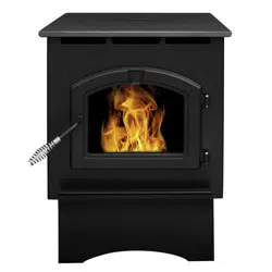
PH35PS SERIES - MEDIUM PELLET STOVE WITH PEDESTAL
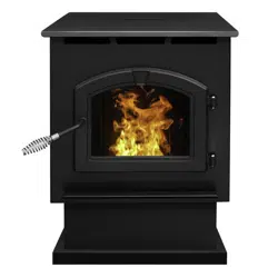
PH50PS SERIES - LARGE PELLET STOVE WITH PEDESTAL AND BASE PAN
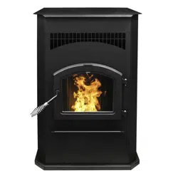
PH50CABPS SERIES - CABINET PELLET STOVE
High Eciency Pellet Stove
SAFETY NOTICE: PLEASE READ THIS ENTIRE MANUAL BEFORE
INSTALLATION AND USE OF THIS PELLET FUEL
BURNING ROOM HEATER. FAILURE TO FOLLOW
THESE INSTRUCTIONS COULD RESULT IN PROPERTY
DAMAGE, BODILY INJURY OR EVEN DEATH. CONTACT
LOCAL BUILDING OFFICIALS ABOUT RESTRICTIONS
AND INSTALLATION INSPECTION REQUIREMENTS IN
YOUR AREA.
SAVE THESE INSTRUCTIONS
6440 W. Howard St.
Niles, IL 60714
877-447-4768
PH35PS-B PH50PS-B PH50CABPS-B
Certied to ULC S627
and ASTM E1509
PH50PS-B & PH50CABPS-B,
Emissions Report No: 19-470
PH35PS-B, Emissions
Report No: 0061PS095E
7077-801D • September 17, 2019
(877) 477- 4768
2
Lighting Instruction Guide
CAUTION
Follow all instructions and warnings for safe startup of stove. Failure to follow instructions could result in
injury or damage.
During startup and normal operation your appliance’s front door must be closed.
Odors and vapors are released during initial startup after purchase. Burning your appliance on HI for 30 minutes will
allow the paint to cure. Open windows or doors for air circulation until burn-off is complete.
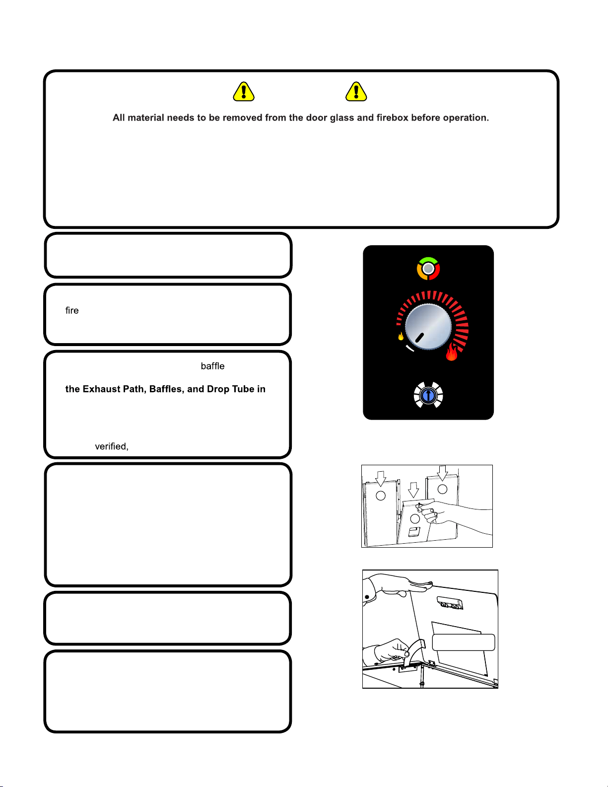
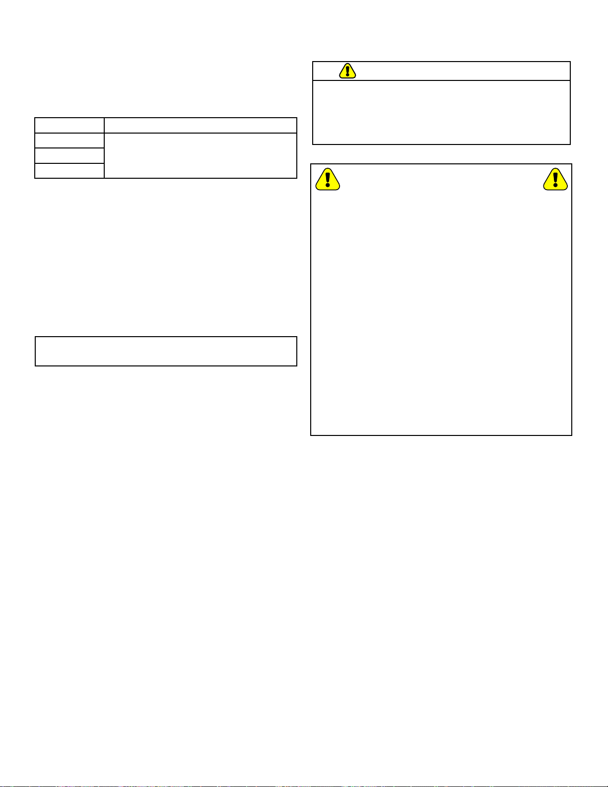
1.
Turn Dial Control to OFF and ensure appliance is
completely shut down, Figure 2.1.
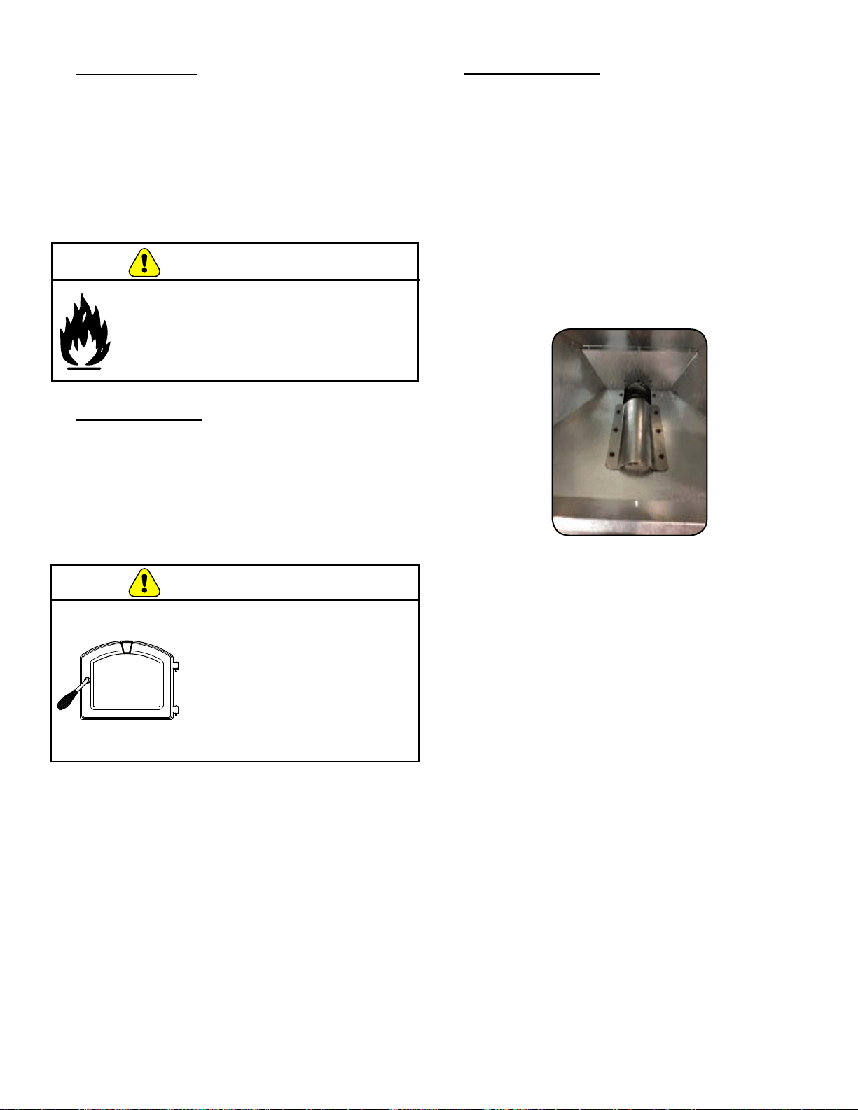
3.
Open front door and ensure all
are
installed properly, Figure 2.2 (also see Clean
the General Maintenance section of Owner’s
Manual under Maintaining and Servicing the
Appliance).
*Once close door.*
2.
Ensure appliance is completely cooled and clean
pot (see Cleaning Fire pot in the General
Maintenance section of Owner’s Manual under
Maintaining and Servicing the Appliance)
NOTE: If the appliance fails to ignite, the LED light will
blink red 4 times continuously indicating a missed
ignition alarm; repeat lighting steps 1 through 5.
NOTE: It may take up to 20 minutes for a missed
ignition alarm.
Figure 2.1
Figure 2.2
33
11
22
4.
Inspect hopper and ensure there is pellet fuel in
the hopper. If there is fuel in the hopper, close lid
and proceed to step 5, Figure 2.3.
NOTE: If the hopper is completely empty, the
appliance will need to have pellet fuel added to the
hopper and may need to be primed (see Priming
The Feed Tube in the General Operating Infor-
mation section of Owner’s Manual).
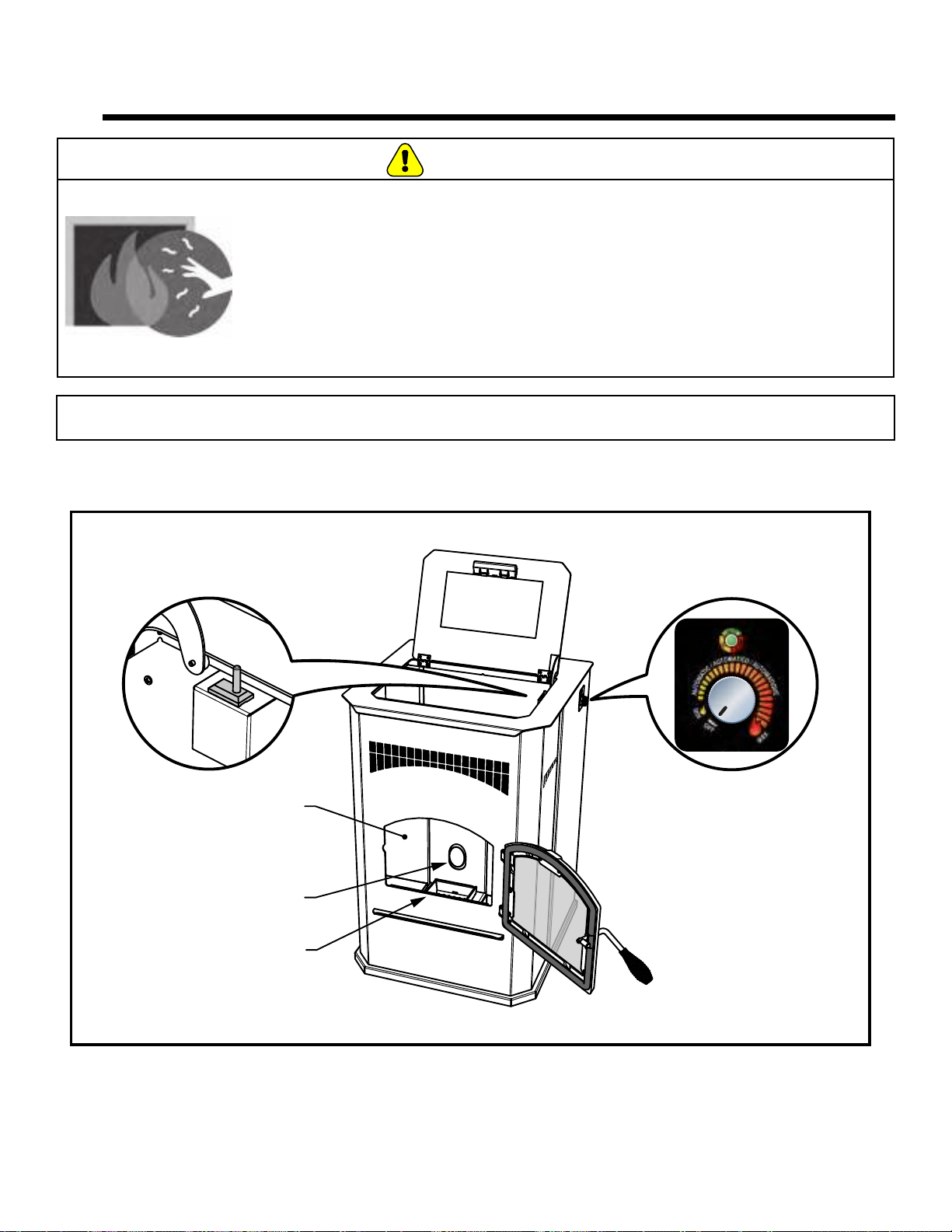
5.
Turn dial control to desired setting.
-Green light will start blinking rapidly to indicate
startup sequence.
Push Bottom of Latch
Inward to Release
Figure 2.3
Lighting Instructions • December 06, 2016
0
-
1
-
2
-
3
-
4
+
1
+
2
+
3
+
4
A
U
T
O
M
A
T
I
C
/
A
U
T
O
M
Á
T
I
C
O
/
A
U
T
O
M
A
T
I
Q
U
E
O
F
F
M
A
X
M
I
N
O
N
A
U
T
O
A
L
A
R
M
7077-801D • September 17, 2019
3
TABLE OF CONTENTS
Safety Alert Key:
• DANGER! Indicates a hazardous situation which, if not avoided will result in death or serious injury.
• WARNING! Indicates a hazardous situation which, if not avoided could result in death or serious injury.
• CAUTION! Indicates a hazardous situation which, if not avoided, could result in minor or moderate injury.
• NOTICE: Indicates practices which may cause damage to the appliance or to property.
1 Listing and Code Approvals ..... 5
A. Appliance Certication ............................5
B. BTU & Eciency Specications
.....................5
C. Glass Specications
..............................6
D. Electrical Rating (On High)
.........................6
E. Mobile Home Approved
............................6
F. Non-Combustible Materials
.........................6
G. Combustible Materials
............................6
H. Sleeping Room
..................................6
I. California - PROP65
...............................6
User Guide
2 General Information ................... 7
A. Fire Safety......................................7
B. Combustible/Non-Combustible Materials . . . . . . . . . . . . . .7
C. Fuel Material and Fuel Storage
.....................7
D. Before Your First Fire
.............................7
3 General Operating Information . 8
A. Y our Pellet Appliance - General Operating Parts ........8
B. User Dial Control
.................................9
C. Filling the Hopper . . . . . . . . . . . . . . . . . . . . . . . . . . . . . . . .9
D. Priming the Feed Tube
...........................10
E. Firepot Burn Down
..............................10
F . Shutdown
......................................10
G. Starting Y our First Fire
...........................10
H. Fire Characteristics
..............................11
I. Ignition Cycles
..................................11
J. Running in Minimum or Maximum
...................11
K. Running in the Automatic Mode
....................11
L. Trim Adjustment
.................................11
M. Clear Space . . . . . . . . . . . . . . . . . . . . . . . . . . . . . . . . . . .11
N. LED Color Coding Chart and Explanation
............12
4 Maintaining & Servicing Your
Appliance .................................... 13
A. Proper Shutdown Procedure.......................13
B. Quick Reference Maintenance Chart
................13
C
.
General Maintenance................................14
D. High Ash Fuel Content Maintenance ................17
E. Frequently Asked Questions
.......................18
5 Replacement Parts .................. 19
A
.
Convection Blower Replacement.......................19
B
.
Exhaust Blower Replacement .........................19
C
.
Snap Disc Replacement .............................20
D
.
Igniter Replacement.................................20
E. Bae Removal & Replacement ....................20
F
.
Glass Replacement .................................21
G. Control Board Replacement .......................21
H. Fuse Replacement . . . . . . . . . . . . . . . . . . . . . . . . . . . . . .21
I
.
Feed Motor Replacement .............................21
J. Feed Spring Replacement.........................21
Install Guide
6 Getting Started ......................... 22
A. Design, Installation & Location Considerations .........22
B. Draft
.........................................23
C. Negative Pressure
..............................23
D. Inspect Appliance & Components
...................23
E. Tools And Supplies Needed
.......................23
7 Dimensions & Clearances ....... 24
A. Appliance Dimensions: PH35PS....................24
B. Appliance Dimensions: PH50PS
....................24
C. Appliance Dimensions: PH50CAB
..................25
D. Clearances to Combustibles (UL and ULC)
...........25
E. Hearth Pad Requirements (UL and ULC)
.............26
8 Vent Information....................... 27
A. Chimney and Exhaust Connection . . . . . . . . . . . . . . . . . .27
B. Venting Termination Requirements
..................27
C. Equivalent Feet of Pipe
...........................28
D. Pipe Selection Chart
.............................28
9 Venting Systems ...................... 29
A. Vertical - Interior - Typical Installation ................29
B. Through The Wall & Vertical - External - Horizontal
.....29
C. Vertical into Existing Class A Chimney
...............29
D. Masonry
......................................30
E. Alternate Masonry
...............................30
F. Through The Wall
...............................31
10 Mobile Home ........................... 32
A. Mobile Home Installation..........................32
11 Appliance Set-Up.................... 33
A. Outside Air Kit Instructions ........................33
B. Power up the Unit
..............................33
12 Troubleshooting ..................... 34
13 Reference Materials ............... 37
A. Component Function.............................37
B. Wiring Diagram
.................................38
C. Replacement Parts
..............................39
D. Service & Maintenance Log
.......................40
E. 5 Year Warranty
................................41
French Manual.....................................................45
Spanish Manual...................................................89
7077-801D • September 17, 2019
(877) 477- 4768
4
CAUTION
After reading these instructions, if you have any doubt
about your ability to complete your installation in a
professional manner you should obtain the services
of an installer versed in all aspects as to the correct
and safe installation. Do not use temporary makeshift
compromises during installation.
BEFORE INSTALLATION OF YOUR APPLIANCE
1. Check with the building inspector’s oce for
compliance with local codes; a permit may be required.
2. Use 3” or 4” (76-102mm) diameter type “L” or
“PL” venting system. It can be vented vertically or
horizontally. Approved adaptors can be used to connect
the “L” or” PL” to approved wood stove venting
such as single wall or double wall venting previously
used to vent a wood burning appliance. INSTALL
VENT AT CLEARANCES SPECIFIED BY THE VENT
MANUFACTURE.
3. Always connect this unit to an approved chimney
system and NEVER vent to another room or inside
a building.
4. DO NOT INSTALL A FLUE DAMPER IN THE
EXHAUST VENTING SYSTEM OF THIS UNIT.
5. DO NOT CONNECT THIS UNIT TO A CHIMNEY FLUE
SERVING ANOTHER APPLIANCE.
6. The connector pipe and chimney should be inspected
periodically and cleaned if necessary. Review
additional information located in the maintenance
section of this Owner’s Manual.
7. Remember the clearance distances when you place
furniture or other objects within the area. This includes
heat sensitive materials such as candles, seasonal
decorations or draperies. DO NOT STORE WOOD,
FLAMMABLE LIQUIDS OR OTHER COMBUSTIBLE
MATERIALS TOO CLOSE TO THE UNIT.
8. Be aware of the required clearances when locating
the unit. Refer to the label on the rear of the unit for
required clearances.
9. Contact your local municipal or provincial re authority
for information of how to handle a chimney re.
Have a clear understood plan to handle a chimney
re. In the event of a chimney re, CALL THE
FIRE DEPARTMENT.
10. Prior to burning the unit for the rst time make sure the
hardware kit has been removed from the rebox.
IMPORTANT
It is highly recommended that the pellet heater and
chimney be installed by a qualied installer. A qualied
installer is a person or entity who regularly installs solid
burning fuel products and chimneys in the course of their
ordinary business.
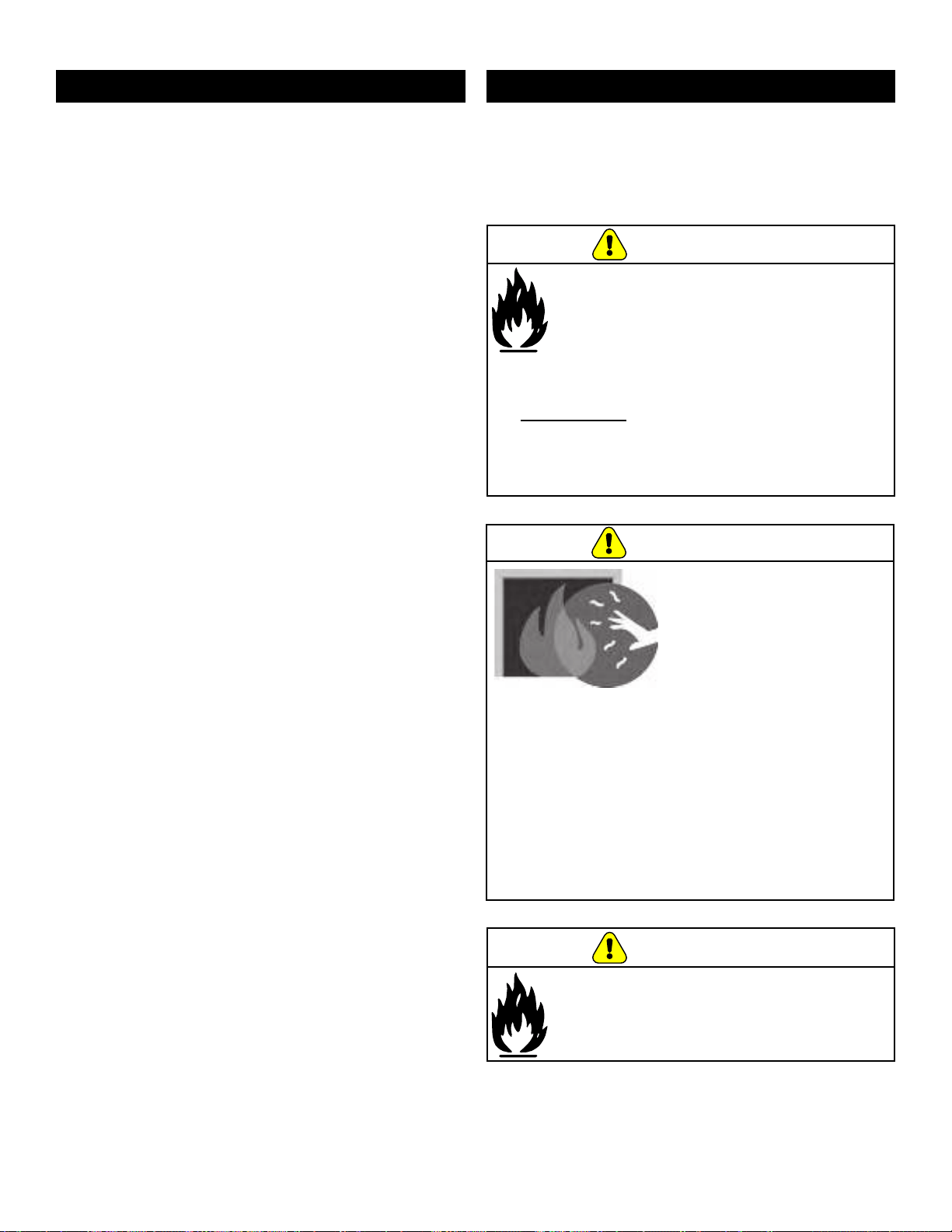
Hot glass will cause burns.
• Do not touch glass until it is cooled
• NEVER allow children to touch glass
• Keep children away
• CAREFULLY SUPERVISE children in same room
as replace.
• Alert children and adults to hazards of high
temperatures.
• High temperatures may ignite clothing or other
ammable materials.
• Keep clothing, furniture, draperies and other
ammable materials away.
HOT SURFACES!
Glass and other surfaces are
hot during operation AND
cool down.
WARNING
If the information in these instructions is not
followed exactly, a re may result causing
property damage, personal injury, or death.
• Do not store or use gasoline or other ammable
vapors and liquids in the vicinity of this or any
other appliance.
• Do not over re - If heater or chimney connector
glows, you are over ring. Over ring will void
your warranty.
• Comply with all minimum clearances to combustibles
as specied. Failure to comply may cause house re.
WARNING
Fire Risk.
Tested and approved for wood pellets. Burning of
any over type of fuel will void your warranty.
WARNING
7077-801D • September 17, 2019
5
A.
Appliance Certication
NOTE: This installation must conform with local codes. In the absence of local codes you must comply with the ASTM
E1509-04, ULC S627-00, (UM) 84-HUD,
Series:
PH35PS-B, PH50PS-B,
PH50CABPS-B
Safety Laboratory: UL LLC
Safety Report No. MH60687
Type:
Solid Fuel Room Heater/Pellet Fuel
Burning Type
Standard:
ASTM E1509-04 and ULC S627-
00, Room Heater Pellet Fuel
Burning type and (UM) 84-HUD,
Mobile Home Approved.
This pellet heater needs periodic inspection and repair for proper operation. It is against federal regulations to operate this
pellet heater in a manner inconsistent with operating instructions in this manual.
PH35PS-B
PH50PS-B
PH50CABPS-B
Emissions
Report No:
0061PS095E 19-470
Emissions
Laboratory:
OMNI PFS-TECO
EPA
Certication
No:
Number: N.A. Number: N.A.
EPA Certied
Emissions:
0.7 g/hr 1.2 g/hr
*LHV Tested
Eciency:
79.4% 81.1%
**HHV Tested
Eciency:
74.6% 75.9%
***EPA BTU
Output:
6,800 to 26,000 /hr 6,900 to 34,100 /hr
****BTU
Input:
9,600 to 33,200 /hr 9,800 to 44,400 /hr
Vent Size: 3 or 4 inches, “L” or “PL”
Hopper
Capacity:
40 lbs. 80/120 lbs.
Fuel Premium Wood Pellets
* Weighted average LHV eciency using data collected
during EPA emissions test.
**Weighted average HHV eciency using data collected
during EPA emissions test.
***A range of BTU outputs based on EPA Default
Eciency and the burn rates from the low and high
EPA tests.
****Based on the maximum feed rate per hour multiplied
by approximately 8600 BTU’s which is the average BTU’s
from a pound of pellets.
B. BTU & Eciency Specications
1 Listing and Code Approvals
The PH35PS-B, PH50PS-B &
PH50CABPS-B is Certied to
comply with 2020 particulate
emission standards.
7077-801D • September 17, 2019
(877) 477- 4768
6
This appliance is equipped with 5mm ceramic glass.
Replace glass only with 5mm ceramic glass. Please
contact GHP
for replacement glass.
E. Mobile Home Approved
• This appliance is approved for mobile home
installations when not installed in a sleeping room and
when an outside combustion air inlet is provided.
• The structural integrity of the mobile home oor, ceiling,
and walls must be maintained.
• The appliance must be properly grounded to the frame
of the mobile home with #8 copper ground wire, and
use only listed double-wall connector pipe.
• Outside Air Kit provided with each unit must be
installed in a mobile home installation.
C. Glass Specications
D. Electrical Rating (On High)
I. California - PROP65
WARNING
This product and the fuels used to operate this product (wood), and
the products of combustion of such fuels, can expose you to
chemicals including carbon black, which is known to the State of
California to cause cancer
, and carbon monoxide, which is known to
the State of California to cause birth defects or other reproductive
harm. For more information go to: WWW.P65Warnings.ca.gov
NOTE: This appliance is approved for installation in
a workshop.
Stove Series Electrical Rating
PH35PS
115 VAC, 60 Hz, Start 2.6 Amps,
Run 0.9 Amps
PH50PS
PH50CABPS
WARNING!
RISK OF FIRE!
GHP disclaims any responsibility for, and the warranty
and agency listing will be voided by the below actions.
DO NOT:
• Install or operate damaged appliance
• Modify appliance
• Install other than as instructed by the manufacturer.
• Operate the appliance without fully assembling all
components
• Over re
• Install any component not approved by the
manufacturer
• Install parts or components not Listed or approved
• Disable safety switches
Improper installation, adjustment, alteration, service or
maintenance can cause injury or property damage.
For assistance or additional information, consult a
qualied installer, service agency or your dealer.
H. Sleeping Room
When installed in a sleeping room it is recommended that
3ft of vertical be installed prior to horizontally exiting the
room and a smoke/CO alarm be installed in the bedroom.
The size of the room must be at least 50ft³ per 1,000 Btu/hr
stove input, if the stove exceeds the room size, out air must
be installed.
F. Non-Combustible Materials
G. Combustible Materials
Material made of/or surfaced with any of the
following materials:
- Wood
- Compressed Paper
- Plant Fibers
- Plastic
- Plywood/OSB
- Sheet Rock (drywall)
Any material that can ignite and burn: ame proofed or not,
plastered or non-plastered.
Material which will not ignite and burn, composed of any
combination of the following:
- Steel
- Plaster
- Brick
- Iron
- Concrete
- Tile
- Glass
- Slate
Materials reported as passing ASTM E 136, Standard Test
Method for Behavior of Metals, in a Vertical Tube Furnace
of 750° C.

7077-801D • September 17, 2019
7
A. Fire Safety
T
o provide reasonable re safety, the following should be
given serious consideration:
• Install at least one smoke detector on each oor of
your home.
• Install at least one carbon monoxide detector on each
oor of your home.
• Locate smoke detector away from the heating
appliance and close to the sleeping areas.
• Follow the smoke detector manufacturer’s placement
and installation instructions and maintain regularly.
• Follow the carbon monoxide manufacturer’s placement
and installation instructions and maintain regularly.
• Conveniently locate a Class A re extinguisher to
contend with small res.
• In the event of a hopper re:
- Evacuate the house immediately.
- Notify re department.
B. Combustible/Non-Combustible Materials
• Combustible Material
- Material made of or surfaced with wood,
compressed paper, plant bers, plastics, or any
material capable of igniting and burning, whether
ame-proofed or not, plastered or non plastered.
• Non-combustible Material
- Material which will not ignite and burn. Such
materials are those consisting entirely of steel,
iron, brick, tile, slate, glass or plasters, or any
combination thereof.
• Non-combustible Sealant Material
- Sealants which will not ignite and burn: Rutland,
Inc. Fireplace Mortar #63, Rutland 76R, Nuex
304, GE RTV106 or GE RTB116 (or equivalent).
C. Fuel Material and Fuel Storage
Pellet fuel quality can greatly uctuate. We recommend that
you buy fuel in multi-ton lots whenever possible. However,
we do recommend trying various brands before purchasing
multi-ton lots to ensure your satisfaction.
Fuel Material
• Made from sawdust or wood by-products
• Depending on the source material it may have a high
or low ash content.
Higher Ash Content Material
• Hardwoods with a high mineral content
• Fuel that contains bark
• Standard grade pellets or high ash pellets
Lower Ash Content Material
• Most softwoods
• Fuels with low mineral content
• Most premium grade pellets
D. Before Your First Fire
1. First, make sure your appliance has been properly
installed and that all safety requirements have been
met. Pay particular attention to the re protection
and venting.
2. Double check that the rebox is empty and the repot
is in place!
3. Close and latch the door.
Clinkers
Minerals and other non-combustible materials such as
sand will turn into a hard, glass-like substance called a
clinker when heated in the repot.
Trees from dierent areas will vary in mineral content. That
is why some fuels produce more clinkers than others.
Moisture
Always burn dry fuel. Burning fuel with high moisture
content takes heat from the fuel and tends to cool the
appliance, robbing heat from your home. Damp pellet fuel
can clog the feed system.
Size
• Pellets are either 1/4 inch or 5/16 inch (6-8mm)
in diameter
• Length should be no more that 1-1/2 inches (38mm)
• Pellet lengths can vary from lot to lot from the same
manufacturer
• Due to length variations, the feed rate may need
adjusting occasionally
Performance
• Higher ash content requires the repot and the ash
drawer to be emptied more frequently
• Hardwoods require more air to burn properly
• Premium wood pellets produce the highest heat output
• Burning pellets longer than 1-1/2 inches (38mm) can
cause an inconsistent fuel feed rate and/or missed
ignitions of feed jams.
Storage
• Wood pellets should be left in their original sealed bag
until using to prevent moisture absorption
• Do not store any pellet fuel within the clearance
requirements or in an area that would hinder routine
cleaning and maintenance
User Guide
2 General Information
7077-801D • September 17, 2019
(877) 477- 4768
8
A.
Your Pellet Appliance - General Operating Parts
WARNING
HOT SURFACES!
Glass and other surfaces are hot during operation AND cool down.
Hot glass will cause burns.
• Do not touch glass until it is cooled
• NEVER allow children to touch glass
• Keep children away
• CAREFULLY SUPERVISE children in same room as appliance.
• Alert children and adults to hazards of high temperatures.
• High temperatures may ignite clothing or other ammable materials.
• Keep clothing, furniture, draperies and other ammable materials away.
NOTICE: If you expect that children may come into contact with this appliance, we recommend a barrier such as a
decorative screen (See your retailer for suggestions).
Baffles (3)
Firepot
Drop Tube
Hopper Lid Switch Dial Control
3 General Operating Information
7077-801D • September 17, 2019
9
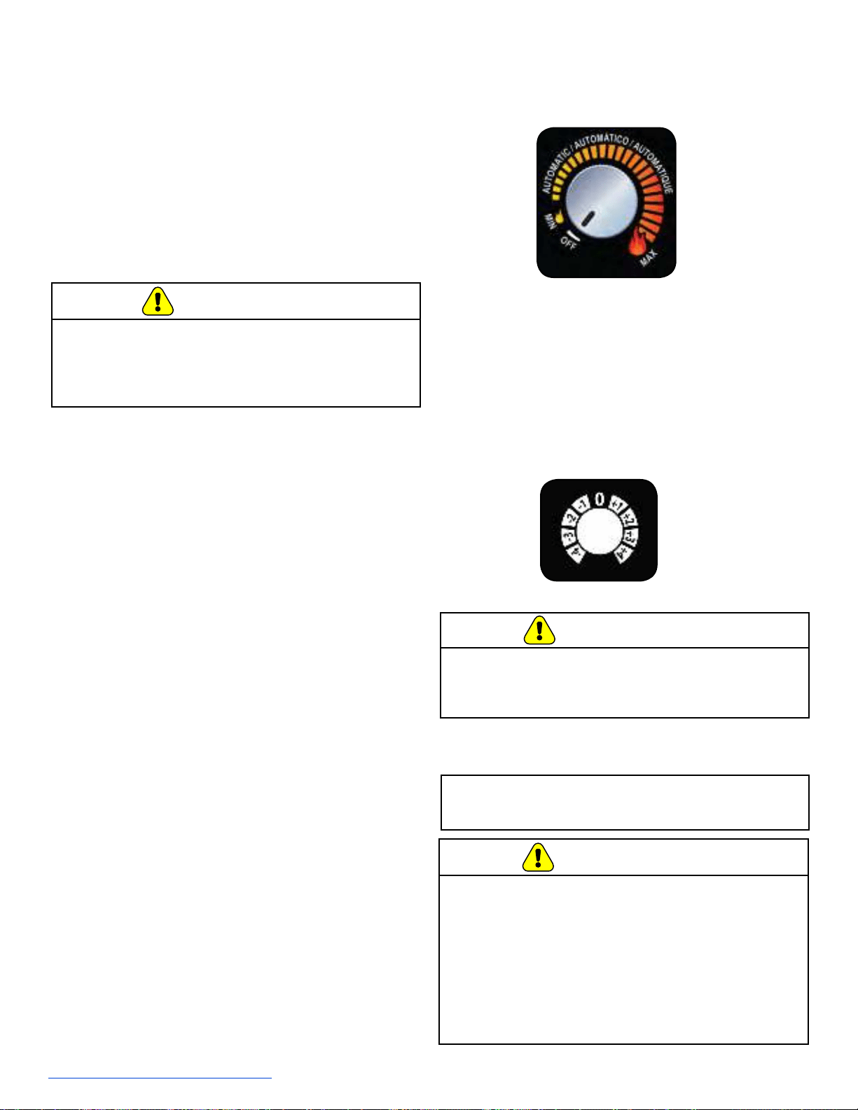
B. User Dial Control
The appliance has one dial control located on the side of
the unit used for daily operation.
There are four primary
settings on this dial.
• O:
- When the dial indicator is in the o position the unit
will go into a shut down and remain o until the dial
is turned to one of the other three settings. The
LED will ash green once per second when in the
o position.
• MIN:
- When the dial indicator is directed to the MIN
setting (small ame on the label) the unit will burn
on low until the hopper runs out of pellets or the
dial control is turned to a dierent setting. When
in this setting the LED will be amber in color and
continuously on. When burning in this mode, the
unit should be turned o at least once daily for
cleaning. If lower quality fuels are used, additional
daily shut downs may be required for cleaning.
• MAX:
- Similar to the MIN mode, the unit will run
continuously at the high burn rate until the unit has
run out of fuel or the dial is turned to a dierent
setting. To operate in this mode, turn the dial
clockwise until it stops. The dial indicator will point
to the large ame. When in this setting the LED will
be amber in color and continuously on. Follow the
daily cleaning recommendations when operating in
this mode. If lower quality fuels are used, additional
daily shut downs may be required for cleaning.
• AUTO:
- To burn in the Automatic mode, turn the dial
control clockwise to the desired comfort level.
When operating in the automatic mode, the unit
changes the burn setting based on the dierence
between the room temperature and the desired
set point. In other words, the unit will burn on High
if the dierence between the desired and room
temperature is greater than 8 degrees Fahrenheit.
As the room heats up and the gap closes, the unit
will automatically reduce the burn rate. When the
room temperature is close to the set point the light
will stop ashing stay solid green. At this time the
stove will be burning on the lowest burn rate. When
the desired temperature is achieved the unit will
shut down. As the room cools, the unit will restart
automatically. When burning in this mode the LED
will be blinking green. The number of green ashes
corresponds to the current burn rate.
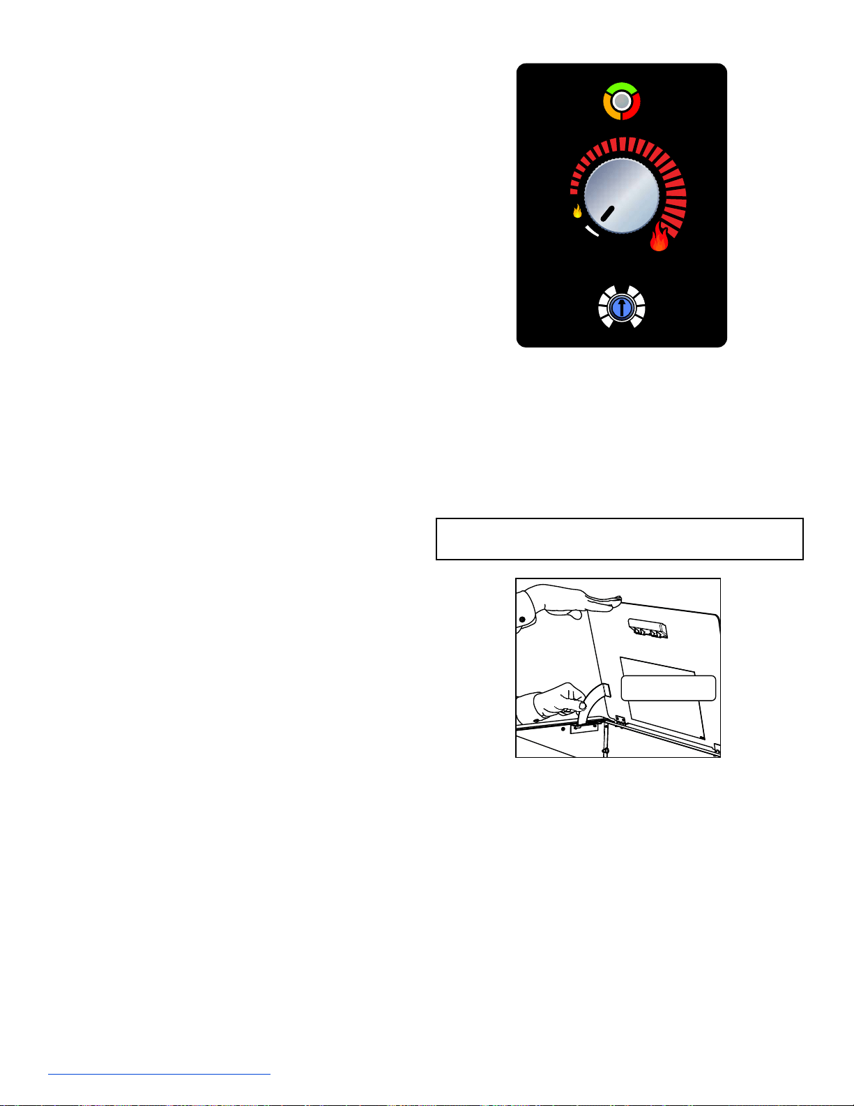
C. Filling the Hopper
Slowly open the hopper lid by lifting the handle. The
medium and large units have a locking latch that will
engage when the hopper lid is fully opened. The hopper lid
for the cabinet will open past ninety degrees and stay open
automatically. Fill the hopper with fuel. FOR USE WITH
ONLY WOOD PELLET FUEL. Slowly close the hopper lid.
See gure below for releasing the latch.
0
-
1
-
2
-
3
-
4
+
1
+
2
+
3
+
4
A
U
T
O
M
A
T
I
C
/
A
U
T
O
M
Á
T
I
C
O
/
A
U
T
O
M
A
T
I
Q
U
E
O
F
F
M
A
X
M
I
N
O
N
A
U
T
O
A
L
A
R
M
Push Bottom of Latch
Inward to Release
NOTE: The unit will not feed with the hopper lid open. If
left open, the re will go out.
7077-801D • September 17, 2019
(877) 477- 4768
10
E. Firepot Burn Down
A
feature of these pellet appliances is the repot burn down
cycle. The frequency of the cycle is once every hour the
appliance is burning. During this event, the feed is reduced
to the lowest setting and the exhaust blower ramps up to
the highest setting. The purpose of the burn down cycle
is to help remove debris from the repot and help the
appliance burn as ecient as possible. The cycle lasts 99
seconds. Please be aware that the burn down does not
replace daily cleaning activities but makes them easier.
F. Shutdown
To shut the appliance down, turn the dial control counter
clockwise to the OFF position. During the shutdown
process, the LED will ash amber or green rapidly just like
the ignition sequence. The repot burn down cycle will
begin but without the feed motor running. The feed will be
terminated during this shutdown process. The exhaust and
convection blowers will remain on during the shutdown
process until the exhaust has cooled.
If maintenance or daily cleaning is going to be conducted
immediately following a shutdown, please use caution as
components especially those inside the rebox may still
be hot.
Please note that if the dial control is turned to the o
position and back on even if by mistake, the appliance
will go through the shutdown sequence.
Return the repot to the appliance in the correct orientation.
See gure in Cleaning Fire pot in the General Maintenance
section of Owner’s Manual under Maintaining and Servicing
the Appliance.
Attempt relighting sequence (see Lighting
Instructions Guide).
MAXIMUM
PELLET LEVEL
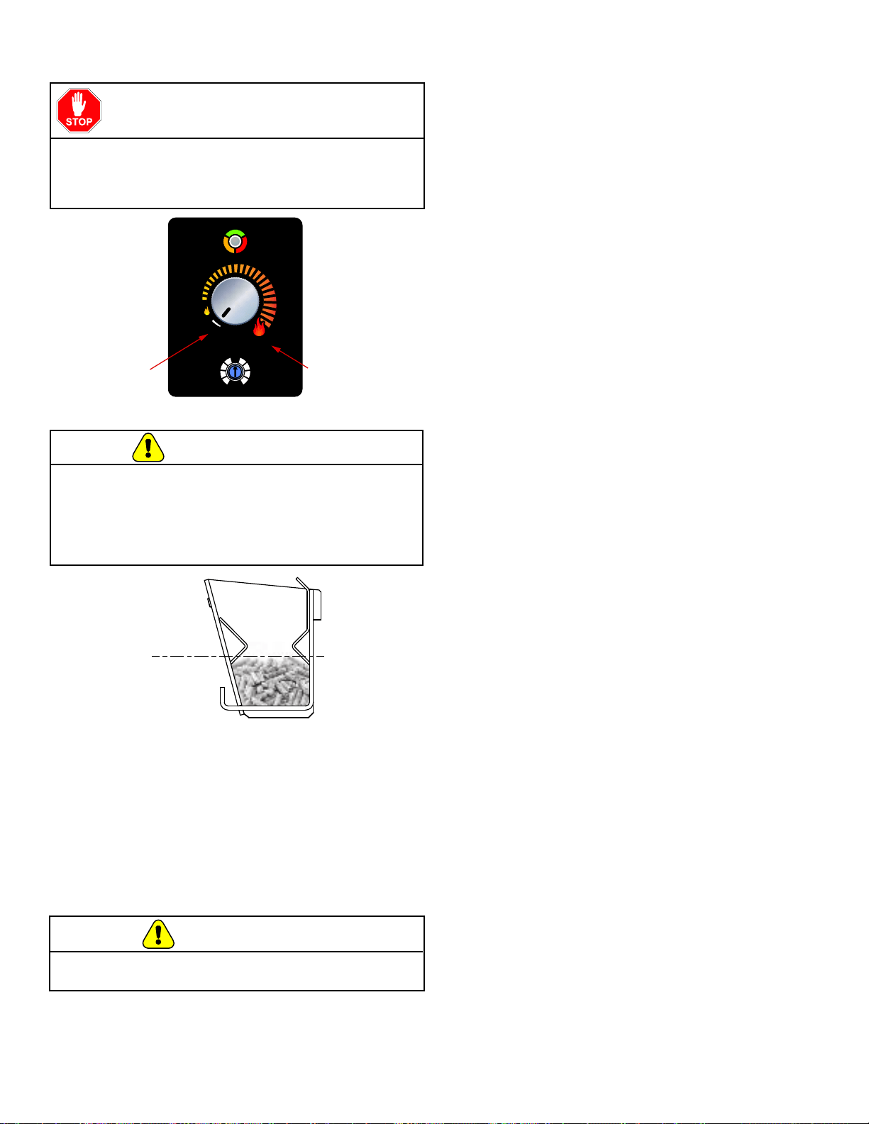
D. Priming the Feed Tube
0
-
1
-
2
-
3
-
4
+
1
+
2
+
3
+
4
A
U
T
O
M
A
T
I
C
/
A
U
T
O
M
Á
T
I
C
O
/
A
U
T
O
M
A
T
I
Q
U
E
O
F
F
M
A
X
M
I
N
O
N
A
U
T
O
A
L
A
R
M
This is the
position for the
dial control
when complet-
ing the prime
function.
This is the
position for the
dial control
when starting
the prime
feature.
The feed tube may need to be primed only if the hopper
is being lled for the rst time or if the appliance has run
out of pellets. To prime the appliance, turn the dial control
QUICKLY from the OFF position to the HI position, to OFF
to HI in one uid motion. The LED light will be a solid green
color to indicate a successful prime function. When the
feed motor is running continuously, the LED light will be a
solid green color. When pellets start to drop into the repot,
the feed tube is primed. Turn the dial control to the desired
position and the appliance will begin its ignition sequence
with a blinking green light. Allow the appliance up to 20
minutes for ignition to occur.
When attempting Prime function it is NECESSARY
to operate the dial control QUICKLY in a single uid
motion. If this is not performed properly, the appliance will
not prime.
STOP!
Please Read Prior to Attempting Prime
Function
A FIREPOT THAT IS MORE THAN HALF FULL IS
OVERFILLED AND CAN BE DANGEROUS. DO NOT
OVERFILL FIREPOT FOR IGNITION.
Overlling the repot could cause an unsafe ignition
resulting in injury or damage. Firepot must be emptied.
WARNING
CAUTION
Do not restart or manually add pellets or any type of fuel to
the burn pot during this process.
G. Starting Your First Fire
1. Turn the dial control to “OFF”.
2. Make sure the repot is clean, in place, and free
of debris.
3. Plug the appliance into the wall and ll the hopper
with wood pellets. Shut the hopper lid.
4. Turn the dial control to the desired burn setting.
The appliance will go into the ignition sequence followed
by start up (The green LED will ash rapidly). The ignition
sequence involves the exhaust blower turning on, the
igniter turning on, and the feed motor running in two
stages. The rst stage involves the feed motor running
continuously for about a minute to preload pellets into the
repot. Following the preload and a delay, the feed motor
will begin cycling on and o. When the pellets are warming
up and on the verge of igniting, it is not uncommon for the
rebox to ll with smoke. Once ignition actually happens,
the smoke should evacuate quickly. During this stage
as well as any part during the burn process, the front
door should not be opened. This cycle continues until
the appliance senses ignition by a rise in the exhaust
temperature or the appliance times out. Following the
ignition cycle the appliance begins to feed additional
pellets gradually for a few minutes to build up the re.
This is important to have a controlled start up to keep the
appliance in balance.
If the appliance does not ignite, the LED light will blink
red four times showing a missed ignition alarm. Turn the
appliance to o and remove and EMPTY the repot.
7077-801D • September 17, 2019
11
H. Fire Characteristics
The overall height of the ame will vary throughout the
burn for a couple of reasons. First is that the ame will vary
based on type of fuel or even batch of fuel. Secondly
, the
appliance adjusts the burn rate according to the how far
away the room temperature is from the set temperature.
This should not cause alarm. The third characteristic
that aects the re relates to general maintenance and
cleaning. Infrequent or poor general maintenance will
result is poorer performance. Indicators of the need for
additional maintenance activities include a lazy ame,
black sooted glass, pellets not igniting, or pellets falling
to the side of the repot. See the maintenance section for
additional information.
Odors, vapors, and smoke released during
initial operation.
• Curing of high temperature paint.
• Open windows for air circulation.
Odors may be irritating to sensitive individuals.
CAUTION
I. Ignition Cycles
1. At the beginning of each ignition cycle, it is normal to
see some smoke in the rebox. The smoke will stop
once the re starts.
2. The convection blower will automatically turn on after
your appliance has been burning for approximately
10 minutes.
3. This blower transfers heat from your appliance into the
room, and will continue to run even after the unit has
shutdown. It will turn o after the exhaust temperature
has cooled.
4. Occasionally the appliance may run out of fuel and
shut itself down. When this happens the empty hopper
alarm will be triggered.
J. Running in Minimum or Maximum
When the dial control is set to run on the minimum or
maximum setting, the appliance will continue to run without
regard to the actual temperature in the room. The appliance
will shut o only if the dial control is set to a dierent setting
or there is an error such as an empty hopper.
When running on minimum or maximum it is important to
follow the daily cleaning activities especially cleaning the
repot. Failure to do so will reduce the performance of
the appliance.
K. Running in the Automatic Mode
When the dial control is set to run in the automatic mode
the unit will adjust the actual burn rate based on the
dierence between the room temperature as sensed by the
probe located in the rear of the unit and the desired comfort
level as set on the dial control.
The comfort level range is from 65 degrees Fahrenheit to
82 degrees Fahrenheit.
M. Clear Space
NOTICE: Clearances may only be reduced by means
approved by the regulatory authority
having jurisdiction.
Mantel: Avoid placing candles and other heat-sensitive
objects on mantel or hearth. Heat may damage
these objects.
WARNING!
RISK OF FIRE!
Do NOT place combustible objects in front or to the sides
of the appliance. High temperatures may ignite clothing,
furniture or draperies.
WARNING!
RISK OF FIRE!
Keep combustible materials, gasoline and other
ammable vapors and liquids clear of appliance.
• Do NOT store ammable materials in the
appliance’s vicinity.
• Do NOT use gasoline, lantern fuel, kerosene,
charcoal lighter uid or similar liquids to start or
“freshen up” a re in this heater.
Keep all such liquids well away from the heater while it is
in use as combustible materials may ignite.
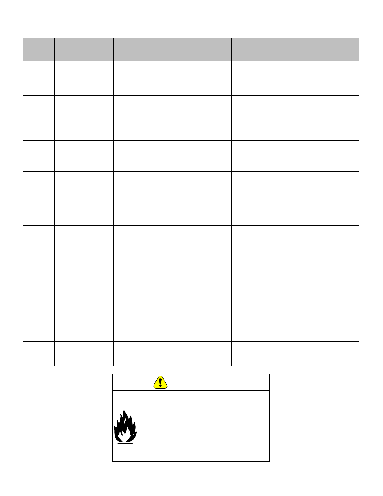
L. Trim Adjustment
Trim adjustment is the small dial located below the main
dial control. Rotating this dial will adjust the air/fuel ratio
and below are examples of when to use it:
• If the re is too large, lazy or producing black soot,
rotate the dial counterclockwise one level at a time
and allow 15 minutes for stabilization before making
another adjustment
• If your re is too small and sometimes goes out
when there are pellets in the hopper, rotate the dial
clockwise one level at a time and allow 15 minutes for
stabilization before making another adjustment.
Once the desired comfort level is achieved the appliance
will automatically shut down and turn o. When the
temperature in the room drops 3 degrees below the desired
comfort level, the appliance will automatically restart.
7077-801D • September 17, 2019
(877) 477- 4768
12
LED
Color
Number of
Flashes between
pauses
Description Notes
Green
Steady ON while
priming feed tube
(max time 2
minutes)
Feed Motor is running continuously.
(This primes the feed tube).
When priming the feed system and lling
the repot, DO NOT OVERFILL FIREPOT
FOR IGNITION. The unit will automatically
go into start up following the prime function.
Green
Steady ON while
burning
Room temperature is close to set point
and burning on lowest burnt rate.
Green 1x Unit is o and ready.
To start appliance, follow start up sequence.
Green
Blinks
Continuously
Appliance is in the start up/ignition
sequence or in shutdown.
During shut down, the blowers will shut o
when the exhaust temperature has cooled.
Green Varies
When in the automatic mode, the
number of ashes between pauses
indicates the burn rate (1 for low up to 5
for high).
Adjust the dial control to change the desired
room temperature.
Amber Steady ON
Appliance is set and running at either the
minimum or maximum power levels.
The unit will shut o only when the hopper
runs out of fuel, the user changes the
dial control to a dierent state, or the unit
senses an error.
Amber
Blinks
Continuously
Appliance is in the in
shutdown sequence.
During shut down, the blowers will shut o
when the exhaust temperature has cooled.
Red
1x
Empty Hopper Alarm
This alarm is caused by the re going
out from lack of fuel. See troubleshooting
section for more information.
Red 2x Exhaust Probe Alarm
Failed component error. See
troubleshooting section for more
information.
Red 3x Ambient Probe Alarm
Failed component error. See
troubleshooting section for more
information.
Red 4x Missed Ignition
There are a total of 2 tries per ignition
sequence. If after 2 tries there is no rise
in exhaust temperature this error will
occur. See the troubleshooting section for
additional information and correction.
Red 8x Exhaust Gas Over Temperature Alarm
The exhaust temperature exceed the
allowable limit. See the troubleshooting
section for more information and correction.
N. LED Color Coding Chart and Explanation
WARNING
Fire Risk
Do NOT operate appliance:
• With appliance door open.
• Firepot oor open.
Do NOT store fuel:
• Closer than required clearances to
combustibles to appliance
• Within space required for loading or
ash removal.
7077-801D • September 17, 2019
13
Cleaning or Inspection
Frequency Daily Weekly Monthly Yearly
Firepot Every 3 bags of fuel OR X
Ash Removal from Firebox Every 5 bags of fuel or more frequently
depending on ash build-up
OR X
Glass When clear view of repot becomes obscure OR X
Hopper Every 25 bags of fuel OR X
Exhaust Path, Drop Tube and
Behind Baes
Every 25 bags or more frequently
depending on ash build-up
OR X
Door Handle & Gasket Inspection Prior to heating season OR X
Blower, Convection Every 25 bags or more frequently
depending on operating environment.
OR X
Blower, Exhaust More frequently depending on the fuel type OR X
Firebox - Prepare for Non-Burn Season At end of heating season OR X
Venting System Every 3 tons or more frequently depending
on the fuel type
OR X
B. Quick Reference Maintenance Chart
Follow the detailed instructions found in this section for each step listed as referenced in the
chart below.
NOTICE: These are recommendations. Clean more frequently if you encounter heavy build-up of ash at
the recommended interval or you see soot coming from the vent. Not properly cleaning your
appliance on a regular basis will void your warranty.
A. Proper Shutdown Procedure
Turn dial control to o, let appliance completely cool and
exhaust blower must be o. After cooling unplug appliance
before servicing.
When properly maintained, your appliance will give you
many years of trouble-free service. Contact your GHP
dealer to answer questions regarding proper operation,
troubleshooting and service for your appliance.
Shock and Smoke Hazard
• Smoke spillage into room can occur if
appliance is not cool before unplugging.
• Risk of shock if appliance not unplugged
before servicing appliance.
CAUTION
4 Maintaining & Servicing Your Appliance
7077-801D • September 17, 2019
(877) 477- 4768
14
•
Frequency: Daily or more often as needed
• By: Homeowner
a. The appliance must be in complete shutdown and
cool and the exhaust blower o. If you are just
cleaning the repot, there is no need to unplug the
appliance.
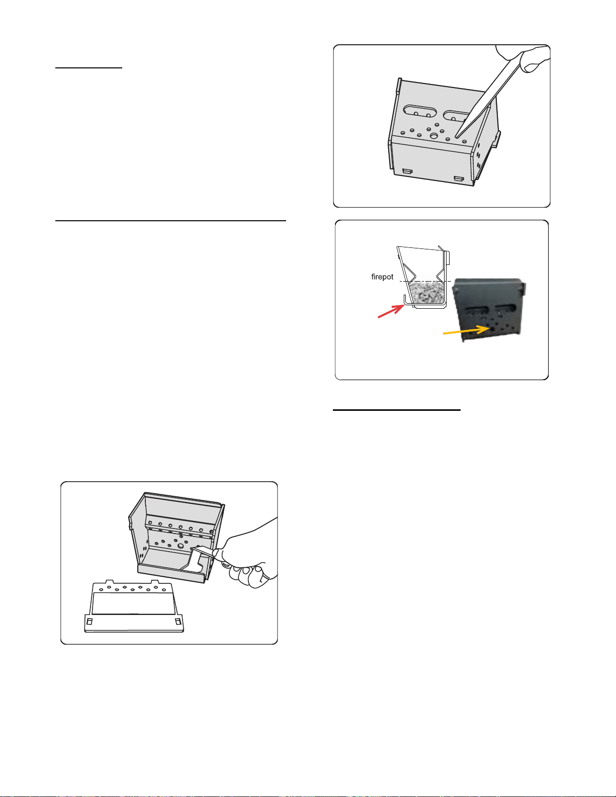
b. Open the front door of the appliance and lift out
the repot. Use the repot cleaning tool to break
up deposits inside the repot and dispose in an
approved container. Depending on the quality of
fuel used, the front of the repot may need to be
removed for better access for cleaning.
c. Use the narrow end of the repot cleaning tool to
clean the holes.
d. With the repot out clean the area below
the repot.
e. Reassemble the repot and place back inside
the repot riser. Make sure the repot is in the
correct direction with the slanted lip in the rear.
Failure to install the repot correctly may result in
missed ignitions.
• Frequency: Weekly or more frequently depending on
ash build-up.
• By: Homeowner
a. There must not be any hot ashes in the rebox
during cleaning so allow the appliance to
completely cool. The rebox ash should be
removed every time the exhaust path is cleaned.
Frequent cleaning of the ash in the rebox will
help slow down the build-up of ash in the exhaust
blower and vent system.
b. Vacuum out the rebox thoroughly on both sides
of the rebox and the oor and ceiling. Remember
to place the ash and debris into a metal or non-
combustible container.
See Disposal of Ashes.
Back
Hole for Igniter
LEVEL
Front of
has the
lip
The type of fuel you are burning will dictate how often you
have to clean your repot.
If the fuel you are burning has a high dirt or ash content,
it may be necessary to clean the repot more than once
a day.
Poor quality fuel will cause clinkers to form in the repot.
A clinker is formed when dirt, ash or a non-burnable
substance is heated to 2000°F (1093°C) and becomes
glass-like. See section D following for more details on fuels
with high ash content.
C
.
General Maintenance
1. Types of Fuel
2. Cleaning Firepot with the Firepot Clean-Out Tool
3. Ash Removal from Firebox
7077-801D • September 17, 2019
15
•
Frequency: As needed
• By: Homeowner
Ashes should be placed in a metal container with a tight-
tting lid. The closed container of ashes should be placed
on a non-combustible oor or on the ground, well away
from all combustible materials, pending nal disposal.
If the ashes are disposed of by burial in soil or otherwise
locally dispersed, they should be retained in the closed
container until all cinders have been thoroughly cooled.
• Frequency: Monthly or after burning 25 bags of fuel
• By: Homeowner
After burning approximately 25 bags of fuel you will need to
clean the hopper to prevent sawdust build-up.
A combination of sawdust and pellets on the bottom end of
the auger reduces the amount of fuel supply to the repot.
This can result in nuisance shutdowns and mis-starts.
a. The appliance must be in complete shutdown.
Allow the appliance to completely run out of pellets
and cool down.
b. Empty the hopper of any remaining pellets.
c. Vacuum the hopper and feed tube. To access the
feed tube remove the four screws from the auger
cover located inside of the hopper.
• Frequency: When clear view of the repot becomes
obscure
• By: Homeowner
a. Appliance must be completely cool before
cleaning glass.
b. Vacuum y ash from glass and door rope.
c. Use a damp paper towel or any non-abrasive glass
cleaner. Wipe o with dry towel.
4. Disposal of Ashes
5. Cleaning the Glass
6. Cleaning the Hopper
WARNING
Disposal of Ashes
• Ashes should be placed in metal container
with tight tting lid.
• Ashes should be retained in closed
container until all cinders have
thoroughly cooled.
Handle glass assembly with care.
When cleaning glass:
• Avoid striking, scratching or
slamming glass.
• Do NOT clean glass when hot.
• Do NOT use abrasive cleaners.
• Refer to
maintenance instructions.
• Do NOT operate with glass
cracked, broken or scratched.
CAUTION
7077-801D • September 17, 2019
(877) 477- 4768
16
•
Frequency: Monthly or every 25 bags or more
frequently depending on ash build-up.
• By: Homeowner
a. Appliance must be completely cool.
b. Open the door and remove the center bae rst
and then the right and left baes. Thoroughly
vacuum the exhaust path and drop tube and
continue throughout the rest of the rebox. Also
vacuum the front and back of the baes.
c. Using a small brush, clean the inner walls of the
exhaust outlet from the access hole inside the
rebox. The access hole will be visible following the
removal of the left side bae. After loosening up
debris on the inner walls of the outlet, vacuum out.
– This is important as the exhaust temperature
probe is attached to the right side of the outlet.
If this is not maintained on a regular basis, the
appliance will experience nuisance shut downs
and/or missed ignitions.
d. Replace the right and left baes and then the
center bae and close and latch the door
.
• Frequency: Monthly or prior to heating season
• By: Homeowner
The gasket between the glass and rebox should be
inspected periodically to make sure there is a good seal.
NOTE: GHP recommends using a heavy duty vacuum
cleaner specically designed for solid fuel
appliance cleaning.
1
2
3
• Frequency: Monthly depending on Dust/Dirt build-up
• By: Homeowner or Qualied Service Technician
a. Be sure the appliance is allowed to cool and has
been unplugged.
b. Remove the right side panel.
c. Sweep or vacuum out any build-up on the
impellers. Use a brush or compressed air to loosen
dirt if needed.
– Avoid damaging the impellers.
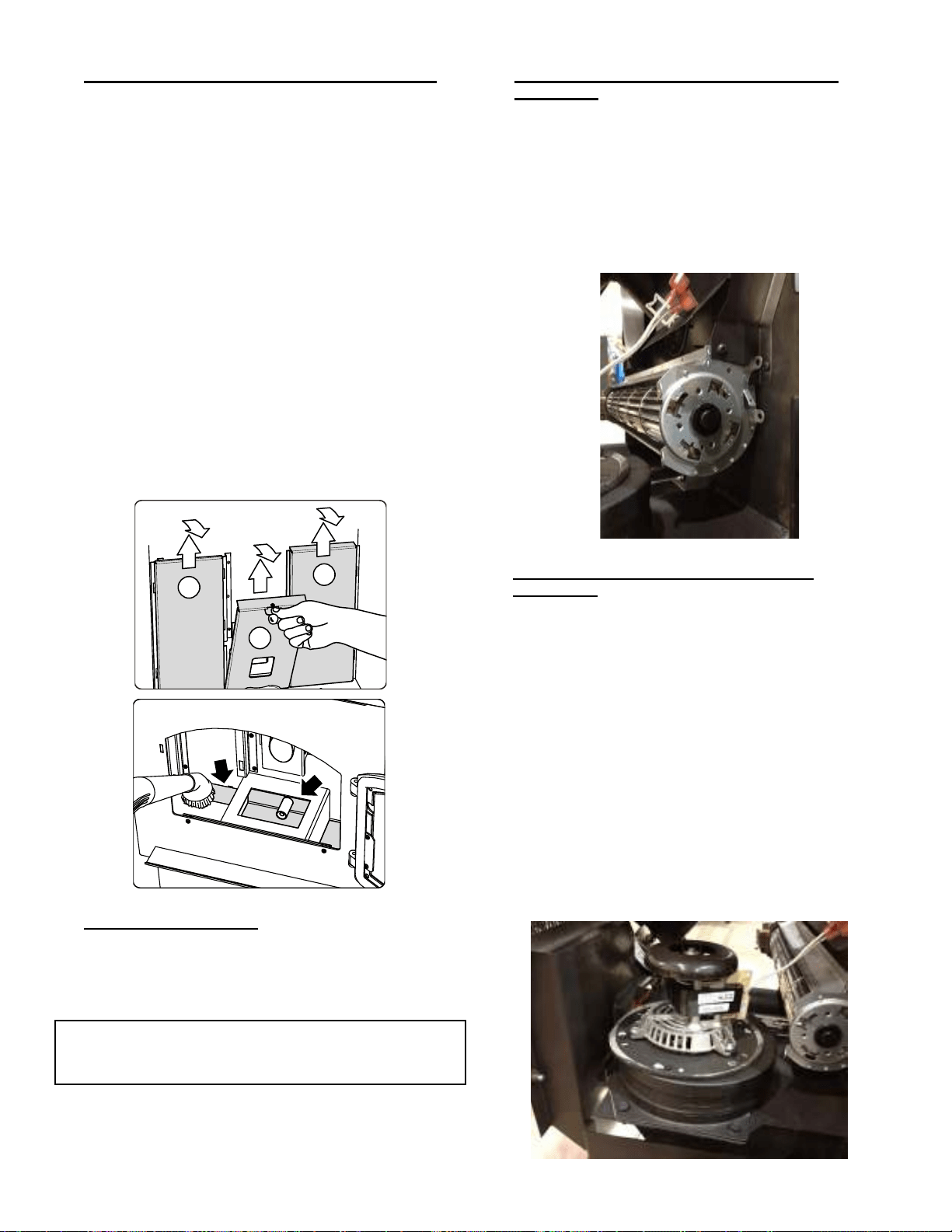
• Frequency: Yearly or more frequently depending on
ash build-up
• By: Homeowner or Qualied Service Technician
a. Be sure the appliance is allowed to cool, has been
unplugged and the exhaust blower is o.
b. Remove the left side panel.
c. Remove the six screws holding the exhaust blower
motor to the housing and remove the motor.
Using caution as to not damage the gasket when
removing the blower. If damage occurs, install a
new gasket available as a replacement part.
d. Vacuum the blower’s impellers. Use care not to
bend or damage the blower ns.
e. Using a brush or vacuum attachment, clean the
inside of the exhaust outlet.
f. Reattach the motor. Make sure the wires are
attached to the terminals on the blower.
7. Cleaning the Exhaust Path, Baes & Drop Tube
8. Door Handle Inspection
9. Cleaning Convection Blower - Requires No
Lubrication
10. Cleaning Exhaust Blower - Requires No
Lubrication
7077-801D • September 17, 2019
17
•
Frequency: Yearly or more frequently depending on
ash build-up.
• By: Qualied Service Technician/Homeowner
Be sure the appliance is allowed to cool, has been
unplugged and the exhaust blower is o.
The products of combustion will contain small particles
of y ash. The y ash will collect in the exhaust venting
system and restrict the ow of the ue gases.
At start-up if there is incomplete combustion, or if there is
a shutdown or incorrect operation of the appliance it will
lead to some soot formation. This will collect in the exhaust
venting system.
The venting (chimney) system may need to be cleaned at
least once a year or more often depending upon the quality
of your fuel or if there are any horizontal pipe sections.
Ash will build up more quickly in the horizontal sections
and elbows.
• Frequency: Yearly
• By: Homeowner
a. Be sure the appliance is allowed to cool, has been
unplugged and the exhaust blower is o.
b. Remove all ash from the rebox and
vacuum thoroughly.
c. Paint all exposed steel, including cast-iron.
– Purchase high temperature paint from your
local retailer
.
– Must use a high-temperature paint made
specically for heating appliances.
11. Preparing Firebox for Non-Burn Season
12. Soot and Fly Ash: Formation & Need for Removal in
Exhaust Venting System.
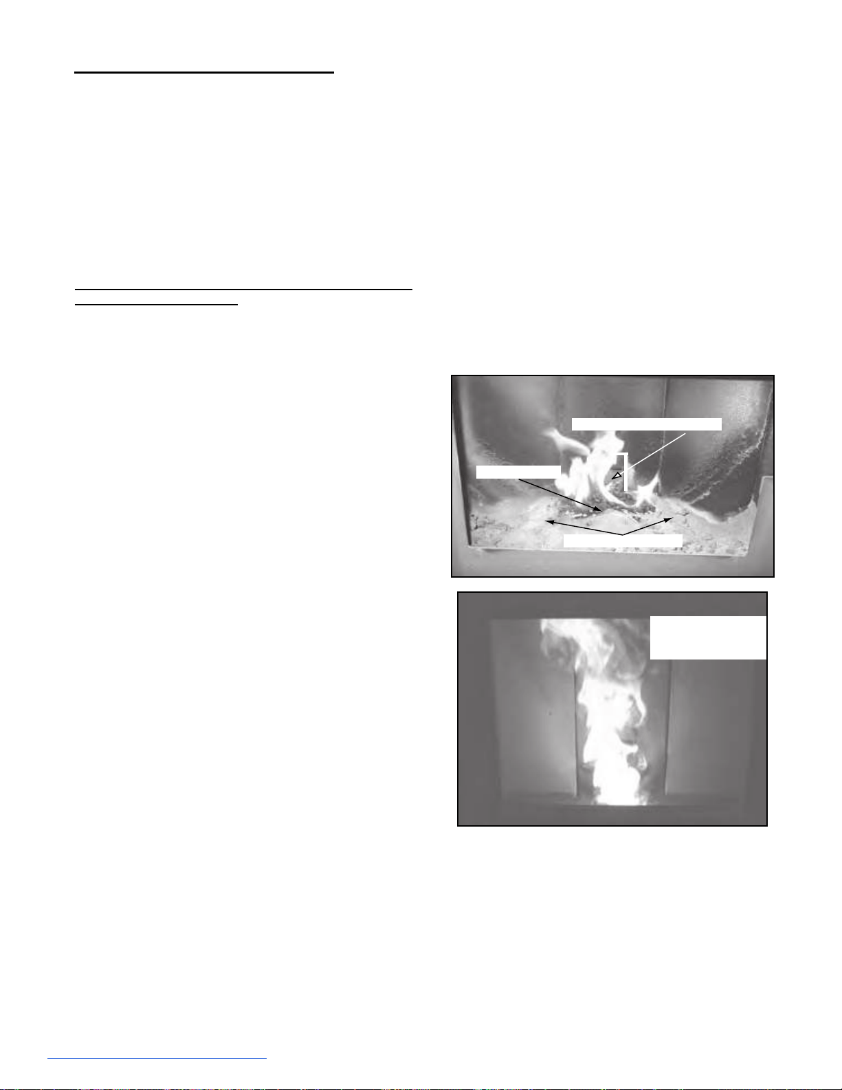
D. High Ash Fuel Content Maintenance
• Frequency: As needed
• By: Homeowner
Poor quality pellet fuel, lack of maintenance, or if the small
dial control is set to a less than optimum setting, poor
combustion conditions that make the repot ll quickly with
ashes and clinkers.
This condition makes the appliance susceptible to
overlling the repot with pellets which may result in
smoking, sooting and possible hopper res. The gure
below shows an example where the repot overlls, pellets
back up into the feed tube and ash has accumulated in
the rebox.
An inecient and non-economical method of burning of fuel
caused by poor quality pellet fuel is shown below.
If the ash buildup exceeds the half way point in the repot
IMMEDIATE ATTENTION AND CLEANING IS REQUIRED.
Incorrect Flame Height
Tall, Lazy Flame
Orange in Color
Pellets Back-up in Feed Tube
Ash build-up in Firebox
Firepot Overfills

7077-801D • September 17, 2019
(877) 477- 4768
18
E. Frequently
Asked Questions
What causes my glass to become dirty?
If the glass has white ash build up it is normal and the glass should be cleaned. If it is a black soot build up airow through
the unit may be restricted. The most often cause is overdue maintenance and cleaning. See “Maintaining and Servicing
Appliance” in the owner’s manual and/or make adjustments to the trim control.
How can I get more heat out of the appliance?
The most often cause of diminished heat output is overdue maintenance and cleaning. See “Maintaining and Servicing
Appliance” in the owner’s manual.
What should I do if I smell smoke or there is ash/soot coming from the appliance?
While there will always be some smoke smell from wood burning appliances (including pellet) you should investigate all
venting to make sure it is sealed properly. Most venting requires silicone to seal the seams. In addition most homes are
built very tight today and with exhaust systems can create negative pressure in the home. See “Negative Pressure” under
“Getting Started” in the owner’s manual if you have checked the venting but still have smoke coming from the appliance.
For ash or soot check the above and the exhaust blower housing and seals.
Why would my appliance run ne last winter but not start this fall?
It is possible that the stove was not properly prepared for the Non-burn season. See “Troubleshooting” in the owner’s
manual.
Why would the metal on the inside of the appliance begin to ake?
There are some pellet mills that get their raw materials from lumber mills that purchase logs that are transported in
sea water. These pellets can have a higher salt content and cause the metals in the unit to corrode prematurely and
deteriorate. If you are seeing any components inside the rebox deteriorate it is recommended to change pellet brands
immediately.
Is there a place to lubricate the blowers to quiet them down?
The most often cause of noisy blowers is from the impellers becoming dirty over time. See “General Maintenance &
Cleaning” under “Maintaining & Servicing Appliance” in the owner’s manual. No form of lubrication should ever need
applied to the blowers.
What is the metal object with the bend in it for that came inside the plastic bag?
It is a clean-out tool used to help clean the repot and remove any jams in the rare event they occur in the feed tube.
Why is there a black residue building up on the outside of my home?
Wind can cause this to happen. If the appliance is operating correctly very little soot should ever exit the termination cap.
Also check to be sure the venting is installed per the owner’s manual and local codes.
Do I need an outside air kit?
Outside air is required for mobile home installs and in some jurisdictions. Refer to “Listing & Code Approvals”,“ Mobile
Home Installation” and “ Appliance Set-up” owner’s manual. Also refer to local building codes.
I am seeing sparks coming out of my pipe (termination cap) outside is this safe?
This is normal. As long as clearances to combustibles were followed this is safe.
I have no power to anything. Does this unit have a circuit breaker or fuse or a reset button?
This unit has one serviceable fuse on the control board and a resetable snap switch mounted to the feed tube.
Can I burn corn in my unit?
NO, corn is not an approved fuel.
Where is the serial # of my unit is located?
The serial # is located on the back of the stove.
7077-801D • September 17, 2019
19
1.
Turn the dial control to the o position. Unplug the
power to the unit.
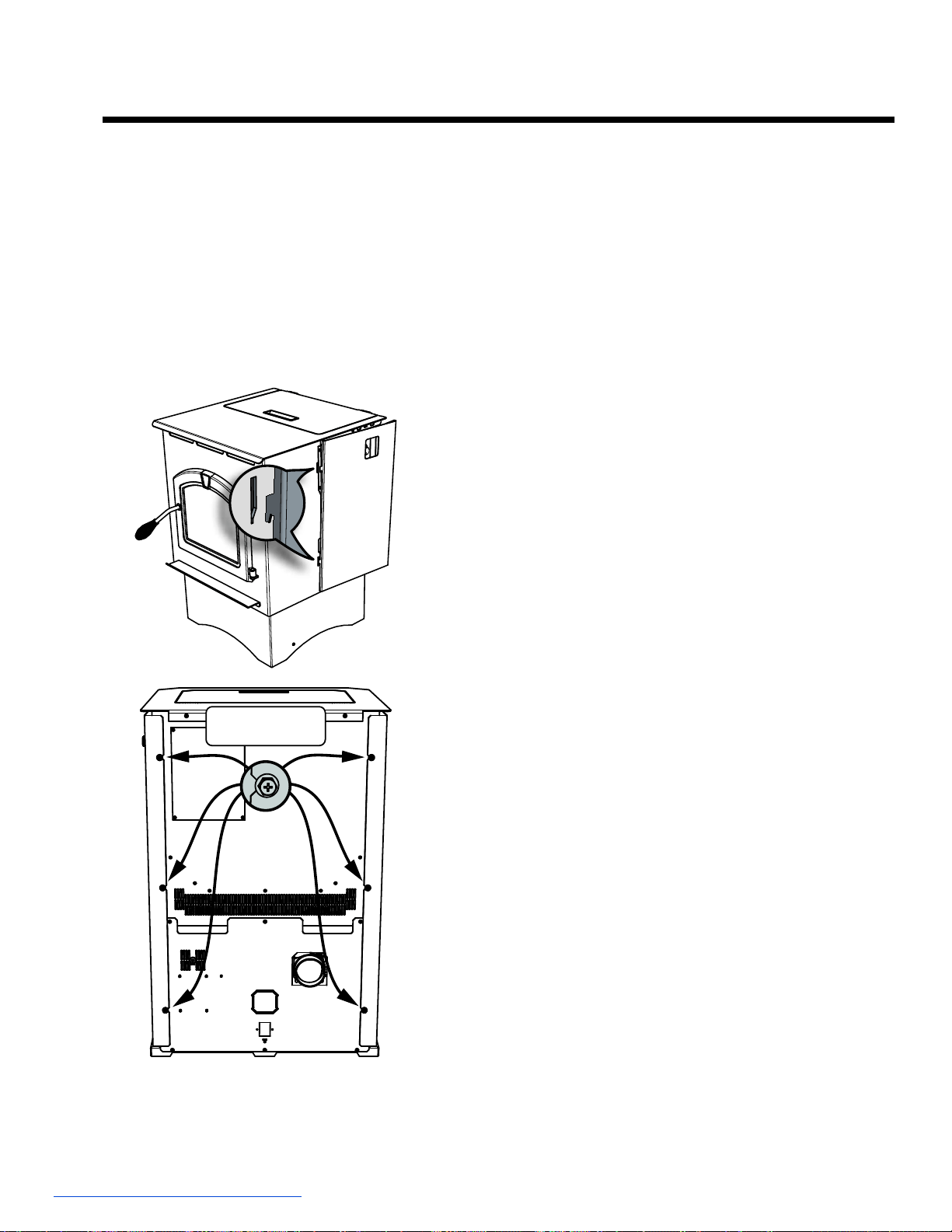
2. The convection blower is located in the rear of the unit.
3. Using #2 Phillips screwdriver, loosen the bolts on the
rear of the unit holding on the side panels. You do not
need to remove the screws. Remove side panels by
lifting up and out.
4. Unplug the wires from the convection blower motor
from the right side of the unit.
5. Remove the two screws holding the convection
blower housing to the sheet metal plenum. Using a
slight twisting motion, rotate the blower back and it
will release.
1. Turn the dial control to the o position. Unplug the
power to the unit.
2. Remove the left side panel by loosening the two or
three bolts in the rear of the unit.
3. Disconnect 2 white wires from the white and blue wires
of the exhaust blower.
4. Remove the blower motor attached to a removable
plate on the exhaust blower. Depending on the model,
use a 1/4 inch socket, or 1/4 inch Nut Driver or #2
Phillips Head screw driver to loosen the 6 screws in the
keyhole shaped holes and rotate the plate. It is only
necessary to loosen screws.
5. Remove the exhaust blower and gasket.
6. Check for degradation on the gasket and replace if
necessary using the gasket included in the kit.
7. Re-install in reverse order.
Loosen Screws,
Do Not Remove
A
.
Convection Blower Replacement
B
.
Exhaust Blower Replacement
5 Replacement Parts
7077-801D • September 17, 2019
(877) 477- 4768
20
Power - Manual Reset
1. Turn the dial control to the o position. Unplug the
power to the unit.
2. Using #2 Phillips screwdriver, loosen the bolts on the
rear of the unit holding on the left side panel. You do
not need to remove the screws. Remove side panels
by lifting up and out.
3. Locate the snap disk on the top side of the feed tube
where it meets the hopper. Disconnect the wire leads
from the snap disk.
4. Using a #1 Phillips screwdriver, remove two 6-32
fasteners retaining the snap disk onto the side of the
feed tube.
5. Using the same fasteners, attach the new snap disk.
Attach the wire leads.
6. Restore power.
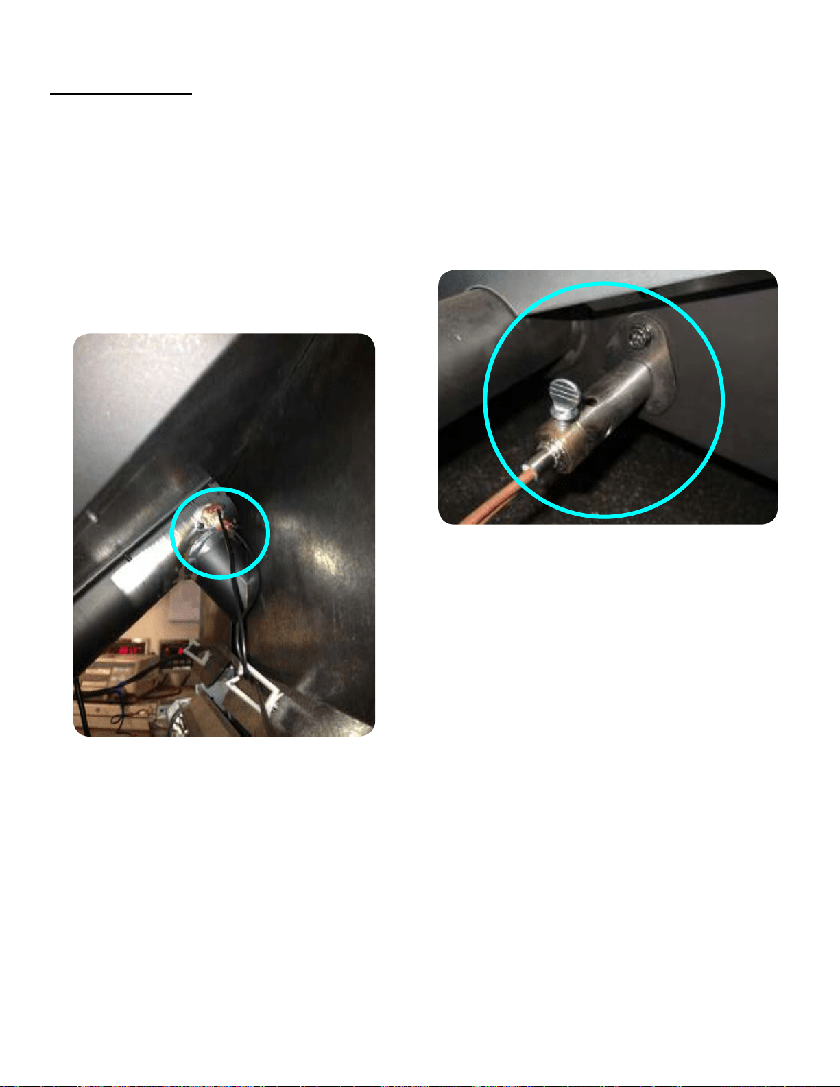
1. Turn the dial control to the o position. Unplug the
power to the unit.
2. Unplug the wire leads to the igniter.
3. Loosen the thumb screw in the side of the
igniter chamber.
4. If there is diculty in removing the igniter from the
chamber, the chamber can be removed from the rear of
the rebox by removing the 1/4-20 bolt.
5. Re-install the new igniter into the chamber. Ensure
igniter ange it ush with back of chamber.
6. Tightening the thumb screw.
7. Re-attach wire to terminals.
1. Turn the dial control to the o position. Make sure the
unit is cool.
2. Remove the center bae rst by using the handle at
the top of the bae and pull up and then towards you.
The hooks on the bae will slide out of the slots in
the bracket.
3. Remove the left bae and then the right bae by
pulling up and then towards you. The left and right
baes have similar hooks and slots.
D
.
Igniter Replacement
C
.
Snap Disc Replacement
E. Bae Removal & Replacement
7077-801D • September 17, 2019
21
1.
Open the door from the appliance by lifting door o of
hinge pins and lay on a at surface face down.
2. Using a Phillips Head screw driver, remove the 3
brackets and set aside.
3. Remove old glass and replace with the new glass.
4. Re-install the brackets using the same screws.
1. Turn the dial control to the o position. Unplug the
power to the unit.
2. Unplug the wires from the control board. The
connectors are locking connectors. Pinch the release
tab on each connector and gently tug and rock loose.
3. Pinch the 4 plastic pins from the rear of the unit to
release the control board connectors.
4. Install new board following the steps in reverse.
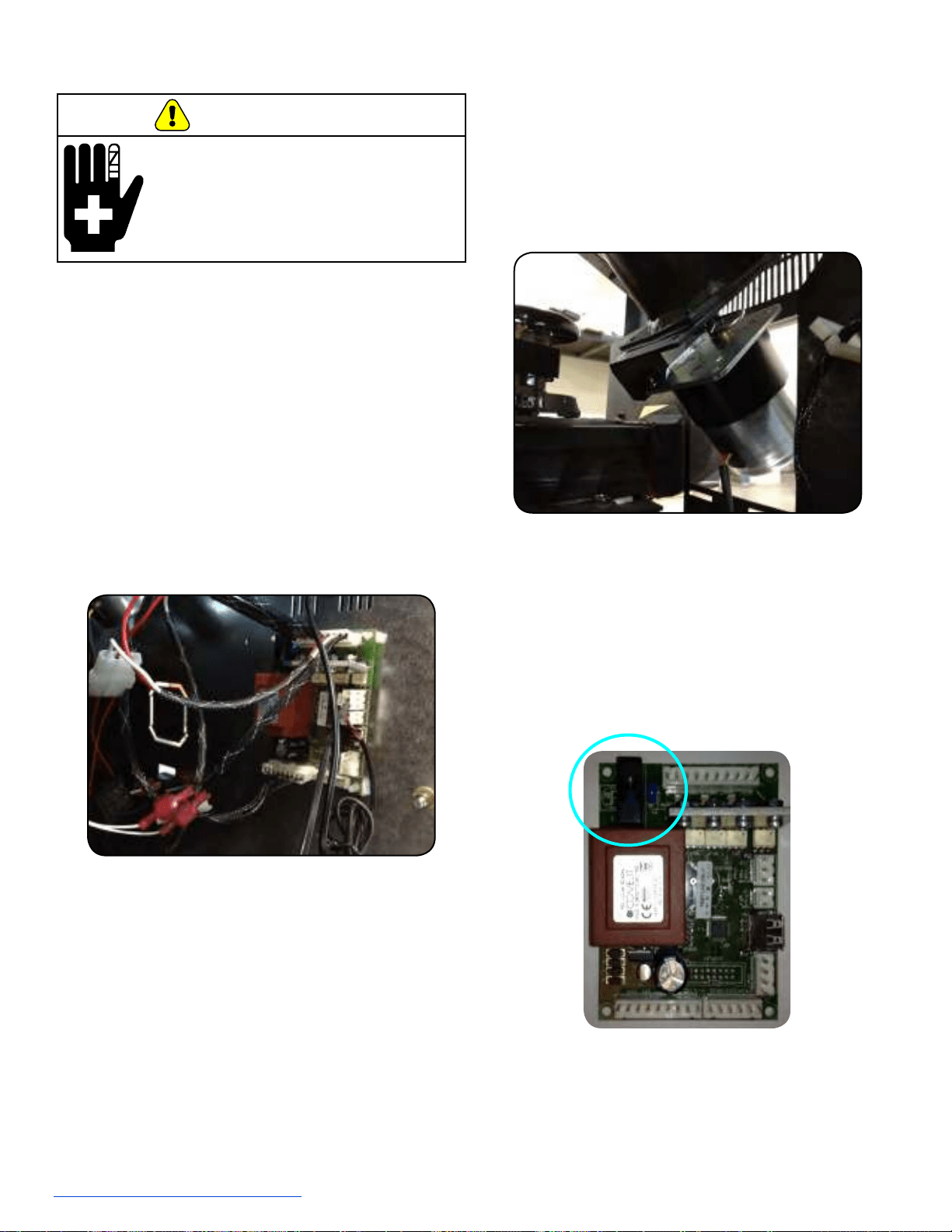
1. Turn the dial control to the o position. Unplug the
power to the unit.
2. Pull the plastic fuse holder cover o the control board.
3. Replace fuse with 5AMP 120VAC fuse only.
4. Replace the cover on the fuse holder and restart unit.
1. Turn the dial control to the o position and unplug the
unit. Remove the right side panel and feed motor cover
plate in the rear of the unit.
2. Unplug the connector from the feed motor.
3. Using pliers, remove the cotter pin.
4. Remove the feed motor from the feed shaft.
5. Reinstall the new feed motor by aligning the clearance
hole in the feed motor shaft with the auger spring shaft.
6. Plug the feed motor leads back in and restore power.
1. Empty the hopper of all pellets then follow the steps to
remove the feed motor above.
2. Remove the four screws holding the feed motor
bracket on.
3. Slide the auger assembly out from the bottom in the
rear of the unit.
4. Inspect the bronze bearings, replace if needed.
5. Install new spring assembly following reverse steps
including reattaching the feed motor.
F
.
Glass Replacement
G. Control Board Replacement
H. Fuse Replacement
I
.
Feed Motor Replacement
J. Feed Spring Replacement
• Glass is 5mm thick high temperature
heat-resistant ceramic glass.
• DO NOT REPLACE with any
other material.
• Alternate material may shatter and
cause injury.
WARNING
7077-801D • September 17, 2019
(877) 477- 4768
22
A. Design, Installation & Location
Considerations
NOTICE: Check building codes prior to installation.
1. Appliance Location
NOTICE: Locating the appliance in a location of
considerable air movement can cause
intermittent smoke spillage from appliance. Do
not locate appliance near:
• Frequently open doors
• Central heat outlets or returns
Install Guide
• Installation MUST comply with local, regional, state and
national codes and regulations.
• Consult insurance carrier, local building inspector,
re ocials or authorities having jurisdiction over
restrictions, installation inspection and permits.
It is a good idea to plan your installation on paper, using
exact measurements for clearances and oor protection,
before actually beginning the installation. Location of the
stove and chimney will aect performance.
Consideration must be given to:
• Safety, convenience, and trac ow
• Placement of the chimney and chimney connector and
to minimize the use of chimney osets.
• Place the stove where there will be a clear passage for
a listed chimney through the ceiling and roof (vertical)
or through exterior wall (horizontal).
• Installing the required outside air kit will aect the
location of the vent termination.
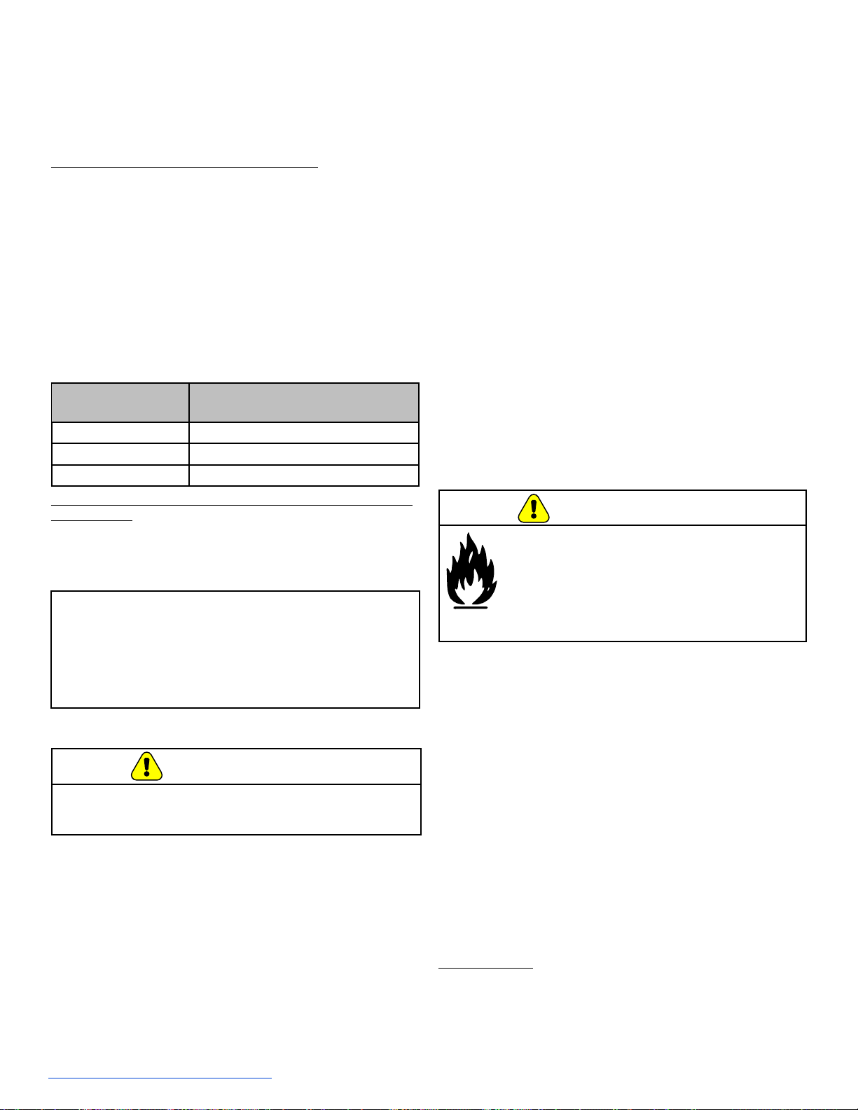
When locating vent and venting termination, the ideal
location is to vent above the roof line when possible. This
minimizes the aects of wind loading.
Since pellet exhaust can contain ash, soot or sparks, you
must consider the location of:
• Windows
• Air Intakes
• Air Conditioner
• Overhang, sots, porch roofs, and adjacent walls
• Landscaping, vegetation
• Horizontal or vertical vent termination
2. Floor Support
The supporting oor under the appliance must be able to
handle the weight of the appliance, fuel load and the weight
of the chimney.
Ensure that your oor will support these weights prior
to installation. Add sucient additional support to meet
this weight requirement prior to installation. The weight
of the stove is 195 pounds and with a full load of fuel the
maximum weight is 145 pounds.
WARNING
Risk of Fire.
Damaged parts could impair safe operation. Do NOT
install damaged, incomplete or substitute components.
Recommended
Location
Marginal
Location
Location
Not
Recommended
Recommended
Location
Location NOT
Recommended
Multi-level Roofs
Windward
Leeward
Outside Air Kit Termination Cap
6 Getting Started
7077-801D • September 17, 2019
23
B. Draft
Draft is the pressure dierence needed to vent appliances
successfully. When an appliance is drafting successfully,
all combustion by products are exiting the home through
the chimney.
Considerations for successful draft include:
• Preventing negative pressure
• Location of appliance and chimney
To measure the draft or negative pressure on your
appliance use a magnehelic or a digital pressure gauge
capable of reading 0 - .25 inches of water column (W.C.).
The appliance should be running on high for at least 15
minutes for the test. With the stove running on high you
should have a negative pressure equal to or greater than
the number given in the chart. If you have a lower reading
than you nd on the chart, your stove does not have
adequate draft to burn the fuel properly.
C. Negative Pressure
NOTICE: GHP assumes no responsibility for the
improper performance of the chimney system
caused by:
• Inadequate draft due to environmental conditions
• Downdrafts
• Tight sealing construction of the structure
• Mechanical exhausting devices
MODEL
Minimum Vacuum
Requirements
PH35PS 0.17 inches W.C.
PH50PS 0.17 inches W.C.
PH50CAB 0.17 inches W.C.
Correct low draft or low vacuum problems by doing one of
the following:
• Thoroughly clean the exhaust path and venting (See
Maintenance Section).
• Inspect for worn or broken gaskets. Repair any gaskets
suspected of leaking, or adjust the trim.
D. Inspect Appliance & Components
• Remove appliance and components from packaging
and inspect for damage.
• Report to your dealer any parts damaged in shipment.
• Read all the instructions before starting the
installation. Follow these instructions carefully
during the installation to ensure maximum safety
and benet.
Tools and building supplies normally required for
installation, unless installing into an existing masonry
replace:
- Reciprocating Saw
- Channel Locks
- Hammer
- Phillips Screwdriver
- Tape Measure
- Plumb Line
- Level
- Framing Material
- Hi-temp Caulking Material
- Gloves
- Safety Glasses
- Framing Square
- Electric Drill & Bits (1/4”)
- 1/4” Self-Tapping Screws
May also need:
- Vent Support Straps
- Venting Paint
E. Tools And Supplies Needed
• Upper level air leaks such as:
- Recessed lighting
- Attic hatch or open windows
- Duct leaks
To minimize the eects of negative air pressure:
• Install the outside air kit with the intake facing
prevailing winds during the heating season
• Ensure adequate outdoor air for all combustion
appliances and exhaust equipment
• Ensure furnace and air conditioning return vents are
not located in the immediate vicinity of the appliance
• Avoid installing the appliance near doors, walkways or
small isolated spaces
• Recessed lighting should be a “sealed can” design
• Attic hatches weather stripped or sealed
• Attic mounted duct work and air handler joints and
seams taped or sealed
Inspect appliance and components
for damage.
Damaged parts may impair safe operation.
• Do NOT install damaged components.
• Do NOT install incomplete components.
• Do NOT install substitute components.
Report damaged parts to dealer.
WARNING
Negative pressure results from the imbalance of air
available for the appliance to operate properly. It can be
strongest in lower levels of the house.
Causes include:
• Exhaust fans (kitchen, bath, etc.)
• Range hoods
• Combustion air requirements for furnaces, water
heaters and other combustion appliances
• Clothes dryers
• Location of return-air vents to furnace or air
conditioning
• Imbalances of the HVAC air handling system
WARNING!
Risk of Asphyxiation!
Negative pressure can cause spillage of combustion
fumes and soot.
7077-801D • September 17, 2019
(877) 477- 4768
24
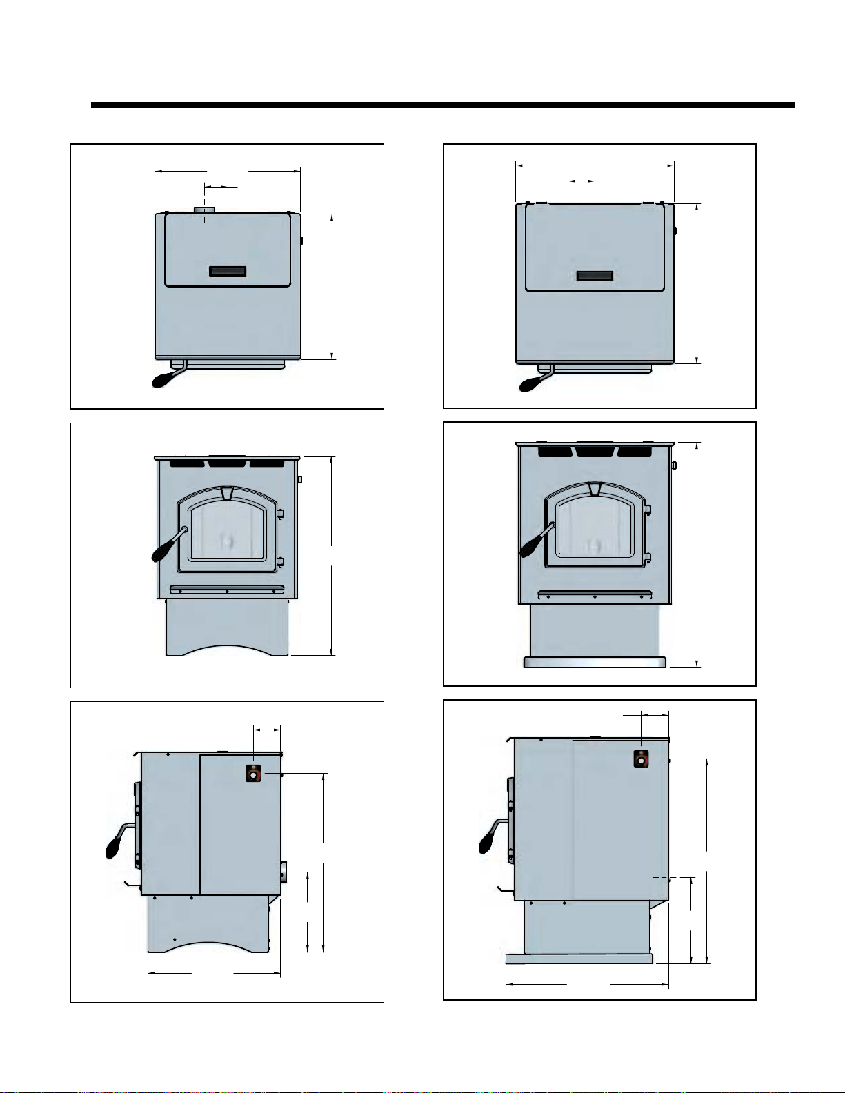
3-1/2
[89]
21-3/4 [552]
21-15/16
[558]
30
[762]
12
[305]
26-13/16
[681]
4-1/8
[105]
19-7/8 [505]
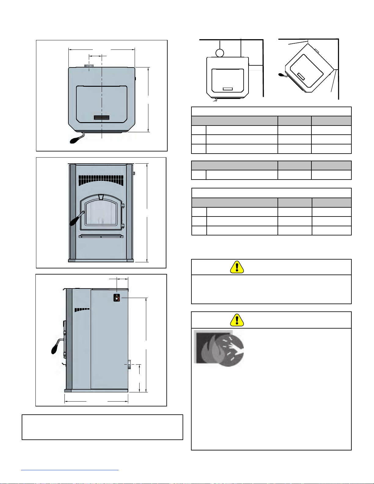
4
[102]
23-3/4 [603]
24-5/16
[617]
34
[864]
13
[330]
30-13/16
[783]
4-1/8
[104]
24-3/8 [620]
A. Appliance Dimensions: PH35PS
B. Appliance Dimensions: PH50PS
7 Dimensions & Clearances
7077-801D • September 17, 2019
25
4-1/2
[114]
23-3/4 [603]
23-3/16
[590]
35-1/2
[902]
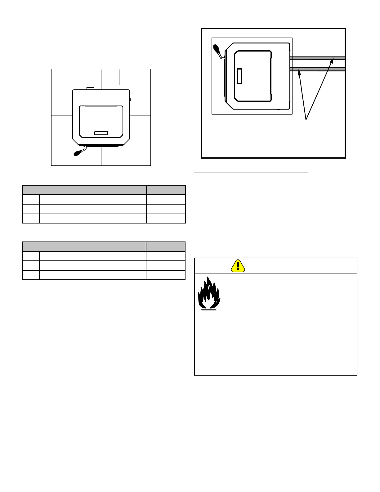
D. Clearances to Combustibles (UL and ULC)
9-1/2
[241]
32-5/16
[821]
4-1/16
[103]
22-11/16 [576]
D
D
B A
C
NOTE: Turn to pages 29, 30 and 31 for side views
and more detailed images of clearances and
installation types.
* Follow pipe manufacture listed clearance
Vertical Installations (Interior Flue)
Straight Back Against Wall Inches Millimeters
A Back Wall to Appliance 2 51
B Back Wall to Flue Pipe 3 76
C Side Wall to Appliance 13 330
Corner Installation Inches Millimeters
D Walls to Appliance 3 76
Horizontal Flue Installations
Straight Back Against Wall Inches Millimeters
A Back Wall to Appliance 2 51
B Back Wall to Flue Pipe 3 76
C Side Wall to Appliance 13 330
C. Appliance Dimensions: PH50CAB
CAUTION
• Do NOT connect this unit to a chimney ue servicing
another appliance.
• Do NOT connect to any air distribution duct
or system.
WARNING
HOT SURFACES!
Glass and other surfaces are hot
during operation AND cool down.
Hot glass will cause burns.
• Do not touch glass until it is cooled
• NEVER allow children to touch glass
• Keep children away
• CAREFULLY SUPERVISE children in same room
as replace.
• Alert children and adults to hazards of
high temperatures.
• High temperatures may ignite clothing or other
ammable materials.
• Keep clothing, furniture, draperies and other
ammable materials away.
7077-801D • September 17, 2019
(877) 477- 4768
26
*Exception for Horizontal Installations:
CANADA INSTALLATIONS: A non combustible oor
protections extending beneath the ue pipe is required
with horizontal venting or under the top vent adapter with
vertical installation.
USA INSTALLATIONS: A non-combustible oor protection
extending beneath the ue pipe is recommended with
horizontal venting or under the top vent adapter with
vertical installation.
A non combustible oor protector is required.
E. Hearth Pad Requirements (UL and ULC)
Use a non-combustible oor protector, extending beneath
appliance and to the front, sides and rear as indicated.
Measure front distance “M” from the surface of the
glass door.
Hearth Pad Requirements Inches
K Sides 2
L* Back 2
M Front 6
Hearth Pad Requirements Millimeters
K Sides 203
L* Back 51
M Front 152
USA Hearth Pad Requirements
Canada Hearth Pad Requirements
Must extend 2 inches (51mm) beyond each
side of pipe (shaded area)
L*
K
M
K
WARNING
If the information in these instructions
is not followed exactly, a re may result
causing property damage, personal injury,
or death.
• Do not store or use gasoline or other ammable
vapors and liquids in the vicinity of this or any
other appliance.
• Do not over re - If heater or chimney connector
glows, you are over ring. Over ring will void
your warranty.
• Comply with all minimum clearances to
combustibles as specied. Failure to comply may
cause house re.
7077-801D • September 17, 2019
27
Do not terminate vent in any enclosed or semi-
enclosed area such as a carport, garage, attic, crawl
space, under a sun deck or porch, narrow walkway or
closely fenced area, or any location that can build up
a concentration of fumes such as a stairwell, covered
breezeway, etc.
CAUTION
A. Chimney and Exhaust Connection
1. Chimney & Connector: Use 3 or 4 inch (76-102mm)
diameter type "L" or "PL" venting system. It can be
vented vertically or horizontally.
2. Mobile Home: Approved for all Listed pellet vent. If
using the 3 inch (76mm) vertical Top Vent Adapter Kit
or the 3 to 6 inch (76-152mm) Top Vent Oset Adapter,
use Listed double wall ue connector. An authorized
Outside Air Kit must be used with manufactured home
installations.
3. Residential: The 3 inch (76mm) vertical Top Vent
Adapter Kit and the 3 to 6 inch (76-152mm) Top Vent
Oset Adapter are tested to use 24 gauge single wall
ue connector or Listed double wall ue connector to
Class A Listed metal chimneys, or masonry chimneys
meeting International Conference of Building Ocials
(ICBO) standards for solid fuel appliances.
4. Install vent at clearances specied by the vent
manufacturer.
5. Secure exhaust venting system to the appliance with
at least 3 screws or rivets per the pipe manufacturer’s
instructions. Also secure all connector pipe joints with
at least 3 screws through each joint.
6. DO NOT INSTALL A FLUE DAMPER IN THE
EXHAUST VENTING SYSTEM OF THIS UNIT.
7. DO NOT CONNECT THIS UNIT TO A CHIMNEY FLUE
SERVING ANOTHER APPLIANCE.
B. Venting Termination Requirements
1. Termination must exhaust above air inlet elevation. It
is strongly recommended that at least 60 inches
(1.5m) of vertical pipe be installed when appliance
is vented directly through a wall. This will create a
natural draft, which will help prevent the possibility of
smoke or odor venting into the home during a power
outage. It will also keep exhaust from causing a
nuisance or hazard by exposing people or shrubs to
high temperatures. The safest and preferred venting
method is to extend the vent vertically through the roof.
2. Distance from doors and opening windows, or gravity
or ventilation air inlets into building:
- Not less than 48 inches (1.2m) below;
- Not less than 48 inches (1.2m) horizontally from;
- Not less than 12 inches (305mm) above.
3. Distance from permanently closed windows;
- Not less than 12 inches (305mm) below;
horizontally from or above.
4. Distance between bottom of termination and grade
should be 12 inches (305mm) minimum. This is
conditional upon plants in the area, and nature of grade
surface. The grade surface must be a non-combustible
material (i.e., rock, dirt). The grade surface must not
be lawn. Distance between bottom of termination and
public walkway should be 7 feet (2.13m) minimum.
5. Distance to combustible materials must be 24 inches
(610mm) minimum. This includes adjacent buildings,
fences, protruding parts of the structure, roof overhang,
plants and shrubs, etc.
6. Termination Cap Location (Home Electrical Service)
- Side-to-side clearance is to be the same as
minimum clearance to vinyl inside corners.
- Clearance of a termination cap below electrical
service shall be the same as minimum clearance to
vinyl sots.
- Clearance of a termination cap above electrical
service will be 12 inches (305mm) minimum.
- Location of the vent termination must not obstruct
or interfere with access to the electrical service.
Vent surfaces get HOT, can cause burns
if touched. Non-combustible shielding or
guards may be required.
WARNING
NOTE: All pipe must be welded seam pipe whenever
possible. Seal pipe joints with high temperature
silicone (500°F [260°C] minimum rated only). Do
not put silicone inside of pipe.
WARNING
Fire Risk.
Follow Chimney Connector Manufacturer’s
Instructions for Proper Installation.
ONLY use connector:
• Within the room, between appliance and ceiling
or wall.
• Connector shall NOT pass through:
- Attic or roof space
- Closet or similar concealed space
- Floor or ceiling
Maintain minimum clearances to combustibles
8 Vent Information
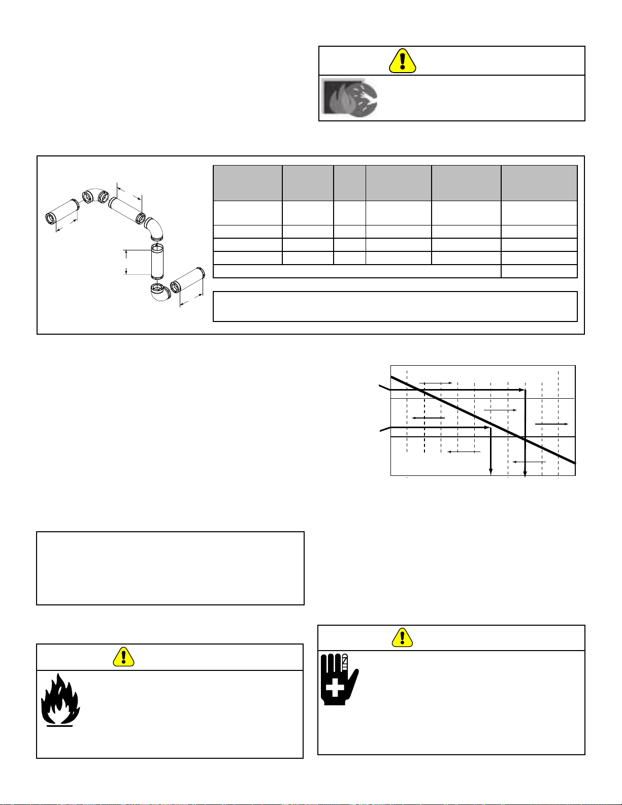
7077-801D • September 17, 2019
(877) 477- 4768
28
C. Equivalent Feet of Pipe
The table below can help you calculate the equivalent
feet of pipe which is a method used to determine pellet
vent size.
2 ft.
2 ft.
3 ft.
2 ft.
Example of 3 Elbow-Rear Vent Termination Calculation
PELLET
VENTING
COMPONENT
# OF
ELBOWS
FEET
OF
PIPE
MULTIPLIED
BY
EQUIVALENT
FEET
COMPONENTS
EQUIVALENT
FEET
90° Elbow
or Tee
3 X 5 15
45° Elbow X 3
Horizontal Pipe 7 X 1 7
Vertical Pipe 2 X 0.5 1
Total Equivalent Feet 23
NOTE: This is a generic example and is not intended to represent any specic
fuel type.
3 in. or 4 in. (76mm or
102mm) Diameter Pipe
3 in. or 4 in. (76mm or
102mm) Diameter Pipe
Equivalent Pipe
Length In Feet
Equivalent Pipe
Length In Feet
ALTITUDE IN THOUSANDS OF FEETALTITUDE IN THOUSANDS OF FEET
0
20
30
1 2 3 4 5 6 7 8 9 10
4 in. (102mm) Diameter Pipe Only4 in. (102mm) Diameter Pipe Only
10
Example 1
Example 1
Example 2
Example 2
Example 1: If the equivalent length of pipe is 23 feet (7m)
with altitude of 8,000 feet (2438m) you must use
4 inch (102mm) diameter type “L” or “PL” vent.
Example 2: If the equivalent length of pipe is 12 feet
(3.7m) with altitude of 6,000 feet (1829m) you
may use 3 or 4 inch (76 to 102mm) diameter
type “L” or “PL” vent.
D. Pipe Selection Chart
The chart will help you in determining proper venting
size according to the equivalent feet of pipe calculated
previously and the altitude above sea level of
this installation.
a. Locate the calculated equivalent feet of pipe on the
vertical left side of the chart.
b. Move to the right horizontally on the chart until you
reach your altitude above sea level.
c. If you fall below the diagonal line, 3 or 4 inch (76 to
102mm) pipe may be used.
d. If it is anywhere above the diagonal line, a 4 inch
(102mm) diameter pipe is required.
Risk of Injury or Property Damage.
• Improper installation, adjustment, alteration,
service or maintenance can cause injury or
property damage.
• Refer to the owner’s information manual
provided with this appliance.
• For assistance or additional information
consult a qualied installer, service agency
or your dealer.
WARNING
Vent surfaces get HOT, can cause burns
if touched. Non-combustible shielding or
guards may be required.
WARNING
Risk of Fire!
• Only LISTED venting components may
be used.
• NO OTHER vent components may
be used.
• Substitute or damaged vent components
may impair safe operation.
WARNING
NOTICE:
• A 90° elbow is 5 times as restrictive to the ow of
exhaust gases under positive pressure as 1 foot
(305mm) of horizontal pipe.
• A foot of horizontal pipe is twice as restrictive as a
foot of vertical pipe.
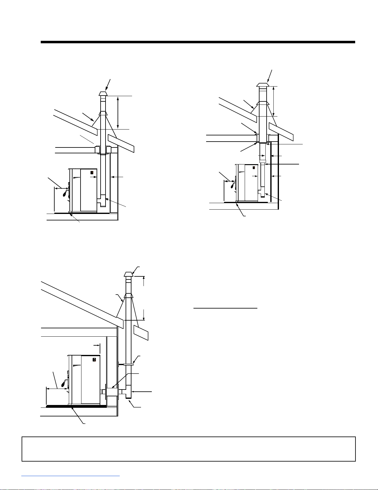
7077-801D • September 17, 2019
29
NOTICE:
These are guidelines for successful venting of your pellet appliance. The more vertical rise you can obtain in
your system, the better it will perform. Horizontal vent runs can accumulate ash and will need to be cleaned
more often. Try to keep them as short as possible.
We strongly recommend a minimum of 60 inches
(1.5m) vertical, however above the eave is preferred.
Both installations are approved for mobile home
installations. Must use 3 or 4 inch (76 to 102mm) “L” or
“PL” Listed pellet venting or Listed double wall pipe and
authorized Outside Air Kit in mobile homes. Single wall
pipe is approved for residential installations only.
Air Clearance to Pipe:
This appliance was tested with standard 3 inch (76mm)
Listed pellet vent.
Pellet pipe manufacturers Listed reduced clearance pipe
may be use for reduce clearance from 3 inch (76mm) air
clearance to no less than 1 inch (25mm) air clearance to
combustibles for approved Listed pellet pipe.
Follow pipe manufactures listed air clearances to
combustibles and installation instructions for all
reduced air clearances installations.
C. Vertical into Existing Class A Chimney
B. Through The Wall & Vertical - External -
Horizontal
A. Vertical - Interior - Typical Installation
PREFERRED METHOD #1
PREFERRED METHOD #2
Firestop
Flashing
Rain Cap
6 in.
(152mm)
Min.
Non-combustible Hearth Pad
follow pipe manufacture
listed clearance
12 in.
(305mm)
Minimum
Clean-out T
Non-combustible Hearth Pad
Clean-out Cover
Te
e
Wall Thimble
Support
Bracket
Every 60 in.
(1.5 m)
12 in.
(305mm)
Minimum
Rain Cap
Flashing
2 in. (5.08 mm) Minimum
6 in. (152 mm)
Minimum
Firestop
Flashing
Rain Cap
Non-combustible Hearth Pad
Follow vent manufacturer’s
clearances for reduced clearances
12 in. (305mm) Minimum
Ceiling Support
6 in. (152mm) Flue
Connector
6 in. (152mm) Class A
Chimney Connector
Adapter
6 in.
(152mm)
Min.
follow pipe manufacture
listed clearance
Clean-out T
9 Venting Systems
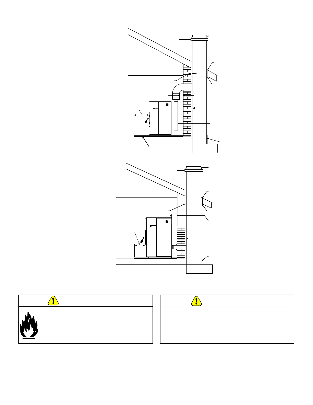
7077-801D • September 17, 2019
(877) 477- 4768
30
E. Alternate
Masonry
D. Masonry
Non-combustible
Hearth Pad
Airtight Clean-out Door
Sheathing
2 in. (5.08mm) Minimum
Flashing
1 in. (25mm) Clearance
1 in. (25mm)
Clearance with Firestop
6 in.
(152mm)
Minimum
Fireclay Flue Liner
with Airspace
Concrete Cap
Tapete para Chimenea Incombustible
Puerta de
Limpieza
Hermética
Limpieza
Revestimiento
3 pulgadas (76
mm) como mínimo
1 pulgada (25 mm) de
espacio libre
T
apajuntas
Ducto de Arcilla
refractaria con
espacio libre
Tapa de
concreto
1 pulgada (25 mm)
de espacio libre con
Firestop
6 pulgadas
(152mm)
Mínimo
Improper installation, adjustment, alteration, service
or maintenance can cause injury or property damage.
Refer to the owner’s information manual provided with
this appliance. For assistance or additional information
consult a qualied installer, service agency or
your dealer.
WARNING
Fire Risk
Inspection of Chimney:
• Masonry chimney must be in good condition.
• Meets minimum standard of NFPA 211
• Factory-built chimney must be minimum 6
inch (152mm) UL103 HT.
WARNING
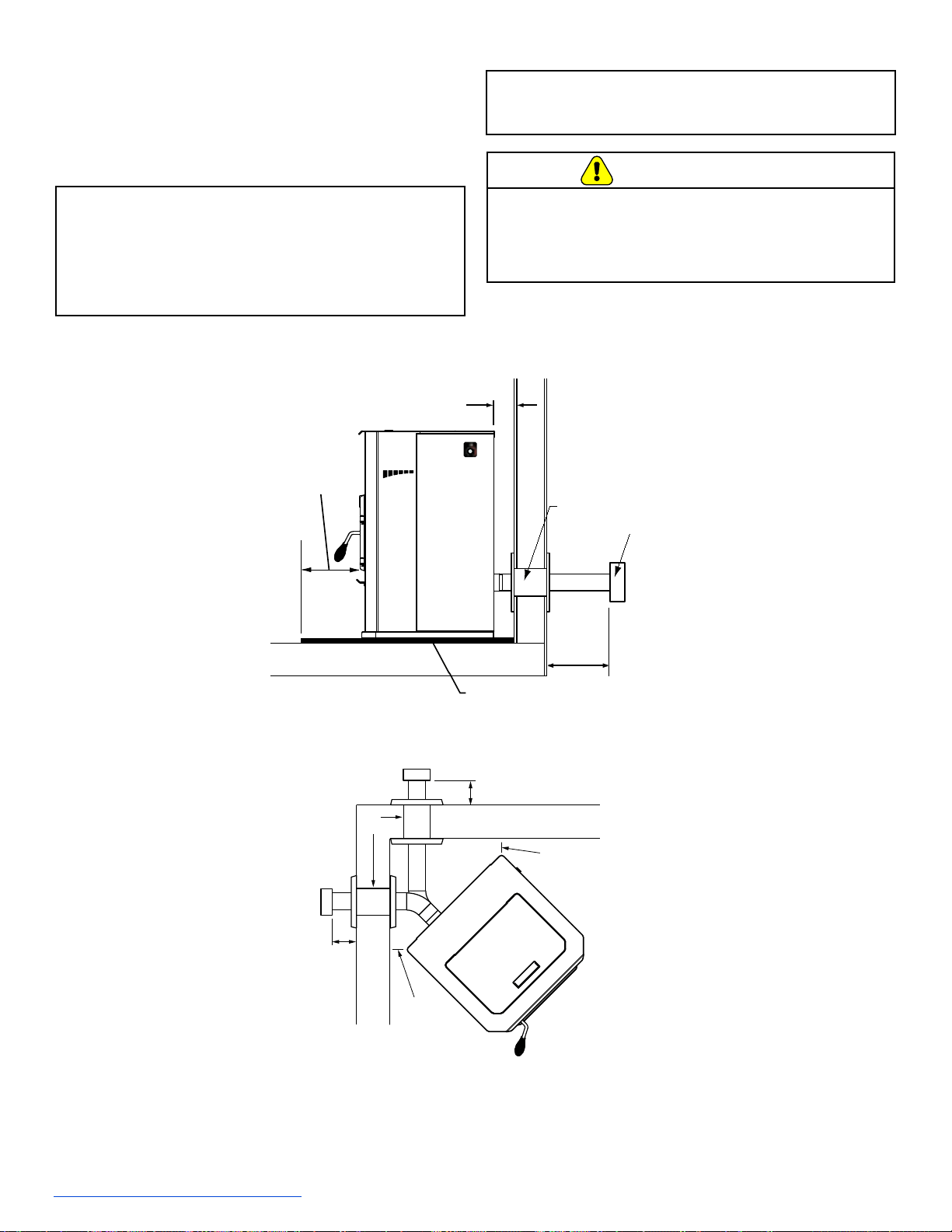
7077-801D • September 17, 2019
31
F
. Through The Wall
Horizontal termination cap must be a minimum of 6
inches. (152mm) from the wall. Approved for mobile home
installations. Must use 3 or 4 inch (76-102mm) “L” or “PL”
listed pellet venting or Listed double wall pipe and an
authorized Outside Air Kit in mobile homes.
NOTE: In Canada, where passage through a wall or
partition of combustible construction is desired,
the installation shall conform to CAN/CSA-B365
NOTICE: Please note that while the minimum clearance
for the termination cap is 6 inches (152mm)
there is the possibly of soot build-up around
the termination area. If this occurs we suggest
to move the termination further away from the
house to prevent it. The suggested minimum
is 12 inches.
Wall
Thimble
Illustration shows venting going in both directions.
Choose which one is best for your installation.
3 in. (76mm)
Minimum
3 in.
(76mm)
Minimum
6 in (152mm) Minimum
6 in (152mm)
Minimum
6 in.
(152mm)
Minimum
Non-combustible Hearth Pad
Wall
Thimble
Horizontal
Termination
Cap
10 in.
(254mm)
Minimum
6 in.
(152mm)
Minimum
From Glass
DO NOT DOWNWARD VENT.
The following will occur:
• The appliance will not vent properly
• Smoke spillage in the house
• Excessive sooting
CAUTION
Straight Out
45 Degrees
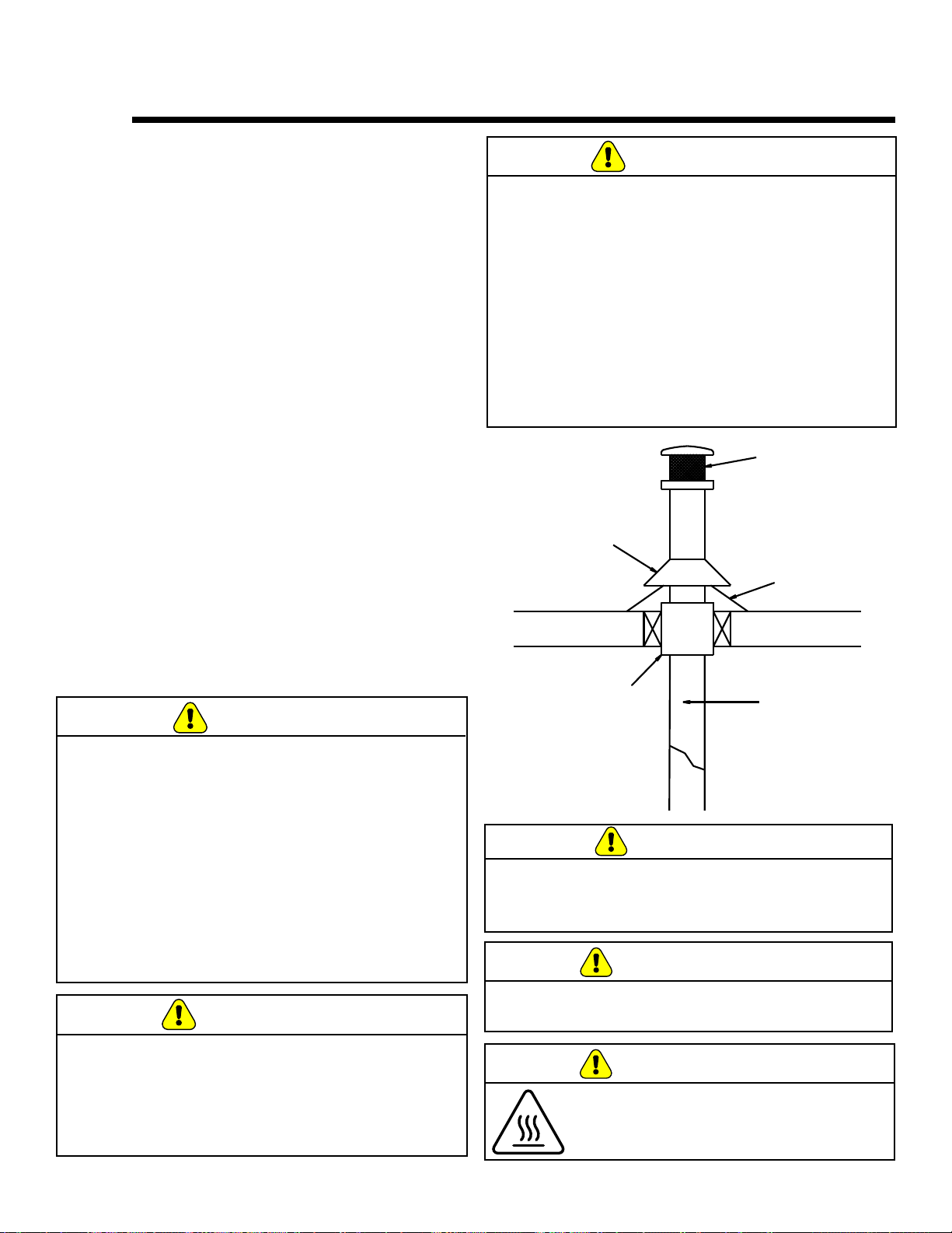
7077-801D • September 17, 2019
(877) 477- 4768
32
1.
An outside air inlet must be provided for the
combustion air and must remain clear of leaves, debris,
ice and/or snow. It must be unrestricted while the
appliance is in use to prevent room air starvation which
causes smoke spillage. Smoke spillage can also set o
smoke alarms.
2. The combustion air duct system must be made of
metal. It must permit zero clearance to combustible
construction and prevent material from dropping into
the inlet or into the area beneath the dwelling and
contain a rodent screen.
3. The appliance must be secured to the mobile home
structure by bolting it to the oor (using lag bolts)
with two attachment points. Use the same holes that
secured the appliance to the shipping pallet.
4. The appliance must be grounded with #8 solid copper
grounding wire or equivalent, terminated at each end
with an NEC approved grounding device.
5. Refer to Clearances to Combustibles and oor
protection requirements for listings to combustibles and
appropriate chimney systems.
6. Use silicone to create an eective vapor barrier at
the location where the chimney or other component
penetrates to the exterior of the structure.
7. Follow the chimney manufacturer’s instructions when
installing the vent system for use in a mobile home.
8. Installation shall be in accordance with the
Manufacturers Home & Safety Standard (HUD) CFR
3280, Part 24.
You must use an authorized Outside Air Kit for
installation in a mobile home.
A. Mobile Home Installation
Spark Arestor Cap
Roof Flashing
Storm Collar
Joist Shield/Firestop
Double Wall
Connector Pipe
CAUTION
Never draw outside combustion air from:
• Wall, oor or ceiling cavity
• Enclosed space such as an attic, garage or
crawl space.
Installation must comply with Manufactured Home and
Safety Standard (HUD), CFR 3280, Part 24.
WARNING
Asphyxiation Risk.
NEVER INST
ALL IN A SLEEPING ROOM.
Consumes oxygen in the room.
WARNING
WARNING
Products of combustion generate carbon monoxide and
dierent fuels generate dierent levels. Carbon monoxide
• Only use approved fuels in this appliance.
• Always keep door shut during operation. Operating
this appliance with doors open can allow CO to leak
into the home.
CO can kill you before you are aware it is in your home.
At lower levels of exposure, CO causes mild eects that
are often mistaken for the u. These symptoms include
headaches, dizziness, disorientation, nausea and fatigue.
The eects of CO exposure can vary greatly from person
to person depending on age, overall health and the
concentration and length of exposure.
CAUTION
THE STRUCTURAL INTEGRITY OF THE MOBILE
HOME FLOOR, WALL AND CEILING/ROOF MUST
BE MAINTAINED
Do NOT cut through:
• Floor joist, wall, studs or ceiling trusses.
• Any supporting material that would aect the
structural integrity.
This stove is to be connected to a factory-built chimney
conforming to CAN/ULC-S629, Standard for 650°C
Factory-Built Chimneys.
For removal of the chimney for mobile home
transportation, contact the proper transportation ocials.
WARNING
It is critical to have a working smoke detector
installed in the home of appliance operation.
• Smoke alarms that are properly installed and
maintained play a vital role in reducing re deaths
and injuries. Having a working smoke alarm reduces
the chance of re related injuries.
10 Mobile Home
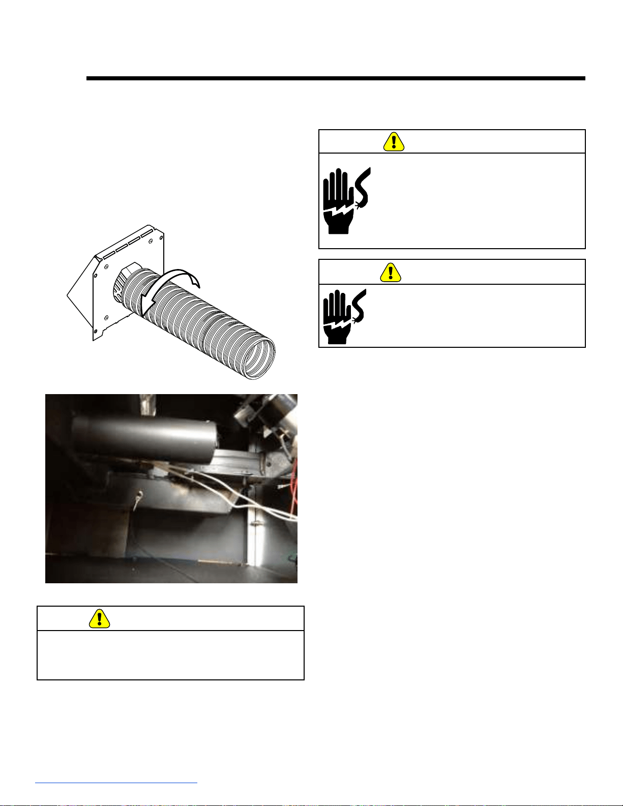
7077-801D • September 17, 2019
33
A. Outside
Air Kit Instructions
An outside air kit has been provide standard with the
appliance. It is highly recommended to use the outside air
kit for maximum performance and to reduce eects from
negative pressure in the home.
For attachment to this platform, knock out the rectangular
plate in the rear of the unit and slide the tube in the rear
of the unit. Using the hose clamp, attach the ex pipe to
the 2” tube welded to the rear of the rebox as shown in
the photo.
B. Power up the Unit
Plug the unit into 120VAC power.
CAUTION
Never draw outside combustion air from:
• Wall, oor or ceiling cavity
• “Enclosed space such as an attic, garage or
crawl space.
Shock hazard.
• Do NOT remove grounding prong
from plug.
• Plug directly into properly grounded 3
prong receptacle.
• Route cord away from appliance.
• Do NOT route cord under or in
front of appliance.
CAUTION
WARNING
DISCONNECT ELECTRICAL SUPPLY
BEFORE SERVICING.
11 Appliance Set-Up
7077-801D • September 17, 2019
(877) 477- 4768
34
Symptom Possible Cause Corrective Action
Plug in appliance -
No response.
No Power to outlet.
5 amp fuse defective or blown
Snap disc tripped or defective.
Check circuit breaker at service panel.
Replace fuse.
Reset or replace snap disc.
Unit Will Not Light
No Fuel
Out of fuel.
Vacuum switch not closing, no vacuum.
Hopper lid open.
Defective hopper switch.
Feed System is Jammed
Feed motor not plugged in
No Igniter
Igniter not plugged in
Igniter not centered
Igniter defective
Firepot Plugged
Firepot dirty
Firepot in backwards
Too much debris in the bottom of the repot
Check hopper. Fill with fuel.
Check exhaust blower is plugged in and
operating.
Check vacuum switch is plugged in
Check vacuum hose is in good condition clear
and connected at both ends
Make sure venting system is clean
Make sure front door is closed
Check vacuum switch tting on side of feed tube
for blockage
Close Hopper Lid
Check hopper switch operation
Inspect and un-jam the feed assembly
Reconnect feed motor
Plug the igniter in
Center the igniter
Igniter seated in chamber completely
Replace igniter
Clean repot
Clean below the repot
Put the repot in the correct direction
Clean repot
Fire starts but goes
out
Firepot is dirty
Exhaust path and/or venting is plugged
Exhaust sensor cannot read correct
temperature
Exhaust path is dirty
Exhaust probe is not attached to outlet
Exhaust probe is not plugged in to the board
Exhaust probe is defective (error code
may result)
Clean repot. Check ue vent for obstruction
Inspect and clean exhaust path and venting
clean rebox including behind the baes
Inspect and clean the exhaust outlet especially
the right side wall.
Remove the right side panel and inspect to see
if the exhaust probe is attached and tight against
the exhaust outlet
Plug the probe into the board
Replace the exhaust probe
Unit start and stops
frequently when
operating in the
automatic mode
Area were the unit is installed heats and
cools quickly depending on installation
conguration. Tight spaces also may have
an eect on the on/o cycling of the unit.
Ambient probe
Probe touching heated surface
Check the proximity to doors and windows and/
or insulation factor of the structure. If heat loss
is quick the unit may need to run on max or
minimum.
Inspect the probe and make sure it is not
touching a surface that heats and cools quickly.
The ambient probe has additional wire inside
rear cavity which can be used to increase the
distance from the unit.
With proper installation, operation, and maintenance your appliance will provide years of trouble-free service. If you do
experience a problem, this troubleshooting guide will assist a qualied service person in the diagnosis of a problem and
the corrective action to be taken. This troubleshooting guide can only be used by a qualied service technician.
12 Troubleshooting
7077-801D • September 17, 2019
35
Symptom Possible Cause Corrective Action
Slow or smoky
start-up and/or lazy
ame
Dirty exhaust and/or venting system.
Not enough combustion air
Misaligned igniter
Wet fuel / poor quality fuel
Check for ash build up in unit, including behind
rear panels, rebox, exhaust blower and venting.
Adjust the trim
Center the igniter in the chamber
Replace fuel
Convection blower
fails to start.
Convection Blower
Jammed
Not plugged in
Exhaust probe
Not sensing correct temperature
Control box is defective.
Inspect, clean, and un-jam the blower.
Plug the blower in
Replace blower
Clean the exhaust outlet especially the right side.
Replace control box.
Exhaust blower fails
to start
Exhaust Blower
Jammed
Not plugged in
Control board is defective.
Inspect, clean, and un-jam the blower.
Plug the blower in
Replace blower
Replace control board.
Convection Blower
Does Not Turn O
Convection blower short circuit. The fuse will
be blown and upon replacement of the fuse,
the blower will run continuously.
Inspect wires, blowers, and power cord to nd
cause of short circuit. Replace board and failed
component.
Convection Blower
makes noise
Screws attaching convection blower to
appliance have become loose.
Convection blower is dirty
Tighten screws
Clean blower impellers
Exhaust Blower Does
Not Turn O
Exhaust blower short circuit. The fuse will be
blown and upon replacement of the fuse, the
blower will run continuously.
Inspect wires, blowers, and power cord to nd
cause of short circuit. Replace board and failed
component.
Igniter does not turn
o
Igniter short circuit. The fuse will be blown
and upon replacement of the fuse, the igniter
will remain on when unit has power.
Inspect wires, blowers, and power cord to nd
cause of short circuit. Replace board and failed
component.
Feed motor does not
shut o
Feed motor short circuit. The fuse will be
blown and upon replacement of the fuse,
the feed motor will remain on when unit has
power.
Open hopper to stop the feed motor.
Inspect wires feed motor, control board, and
power cord to nd source of short circuit.
Replace control board and failed component.
Unit fails to shut o.
Unit running in maximum or minimum
Turn dial control to Automatic or O position.
See Also, “Feed Motor Does Not Shut O”.
The unit should go into a shutdown.
Large, lazy ame,
orange color. Black
ash on glass.
Dirty appliance.
Poor fuel quality, high ash content.
Incorrect air-fuel adjustment
Excessive feeding/Feed Motor locked on
Clean unit, including repot and venting system.
Clean exhaust path. Try a dierent brand of
pellets.
Turn fuel adjustment trim dial to LEFT to
increase combustion air speed.
Follow corrective action for feed motor does not
turn o symptom.
Excessive fuel spilling
over the repot into
the ash wells and/or
excessive ame
Excessive feeding/Feed Motor locked on
Follow corrective action for feed motor does not
turn o.
Black soot on the side
of the house
Exhaust path is dirty.
Excessive feeding/Feed Motor locked on
Incorrect air-fuel ratio
Clean Exhaust path
Follow corrective action for feed motor does not
turn o symptom.
Turn fuel adjustment trim dial to the LEFT to
increase combustion air speed
See “Trim Adjustment” section on Page 9.

7077-801D • September 17, 2019
(877) 477- 4768
36
Alarm
(LED Flashing RED)
Possible Cause Corrective Action
1 Flash:
Empty Hopper
No fuel is delivered to the repot to
sustain ame
Hopper empty (most likely)
Auger Jam (next likely)
No vacuum
Hopper lid open
Flame is evident but the exhaust probe
is not able to recognize the hot exhaust
temperature
Exhaust probe not attached to outlet
Exhaust path is dirty
Fill the hopper, inspect the feed tube for jams,
inspect the venting and rebox for obstructions
and clean if necessary, inspect the exhaust
blower to make sure it runs, or close the hopper
lid.
Inspect and clean the exhaust outlet, rebox,
repot, and behind the baes. Inspect the
exhaust probe to see if it is securely attached to
the side of the exhaust outlet.
2 Flashes:
Exhaust Probe Fail
The exhaust probe
senses a temperature
of less than negative
20 degrees Celsius
or above 300
degrees Celsius.
The exhaust temperature is above or below
the acceptable range.
Exhaust Probe Failure
Not plugged in
Failed component
Plug the probe into the board
Replace the component
3 Flashes:
Ambient Probe Alarm
The ambient probe
senses a temperature
of less than negative
20 degrees Celsius
or above 70
degrees Celsius.
The ambient temperature is above or below
the acceptable range.
Ambient Probe Failure
Not plugged in
Failed component
Plug the probe into the board
Replace the component
4 Flashes:
Missed Ignition
During the ignition
sequence the load
does not ignite. The
unit will automatically
retry once from the
rst failed attempt.
Fuel
No fuel
Hopper Empty
Feed Jam
Feed doesn’t turn
Feed motor disconnected or failed
Firepot
Firepot Dirty so fuel is not near ignition hole
in the repot
Igniter
No power
Debris in the end of the igniter chamber
Fill the hopper
Inspect and clear jam in the feed tube
Inspect the feed motor circuit (hopper lid must
be closed, vacuum switch must be closed (ie.
exhaust blower on), and feed motor must be
plugged in.
Clean the repot
Check leads and if the igniter works. Clean the
end of the igniter chamber from inside the rebox
(removal of the repot required for this step).
8 Flashes:
Exhaust Over
Temperature
The exhaust
temperature
has exceeded
the allowable
temperature.
Fuel
Feed Motor Locked On
Non-approved fuel used
Convection blower
Dirty
Failed
Installation
Installation conguration is tight allowing for
limited air circulation around the unit.
Review the feed motor and feed rates. Normal
feed motor operation is on between 1* and 4*
seconds out of every 7 seconds. (*Depending on
model and burn rate setting)
If the feed motor does not turn o, replace the
control board.
Review the fuel being used.
Clean
Replace
Review the installation and move if necessary.
Following correction of any Alarm, turn the dial control to the OFF position, wait 10 seconds and
turn back to desired setting OR unplug the unit, wait 10 seconds then restore power.

7077-801D • September 17, 2019
37
When describing the location of a component,
it is always
AS YOU FACE THE FRONT OF THE
APPLIANCE.
1. Control Board
The control board is located on the right side of the
appliance behind the lower right side panel.
2. Convection Blower
The convection blower is mounted in the rear of the
unit. It pushes air up the rear of the rebox, across the
top and out the front. As the air moves past the rebox
it is heated.
3. Exhaust Blower
The exhaust blower is mounted on the left side of the
appliance. The exhaust blower is designed to pull the
exhaust from the appliance and push it out through the
venting system.
4. Feed System
The feed system can be accessed in two areas. To
access the auger spring, remove the cover in the
hopper. To remove the feed motor, remove the side
panel and motor cover plate in the rear of the unit.
5. Firepot
The repot is made of a combination of stainless steel
and heavy duty cold rolled steel. It is removable to aid
in cleaning.
6. Fuse
The fuse is located on the control board. The fuse
will blow should a short occur and shut o power to
the appliance.
7. Dial Control
The dial control is attached to the right side of the
appliance. The large dial controls the heat output
where as the small dial below the large dial is the
trim feature. The LED blinks according to the state of
the appliance.
8. Hopper Switch
The hopper switch is located in the upper right hand
corner of the hopper. This switch is designed to
shut down the feed motor whenever the hopper lid
is opened.
9. Igniter
The igniter is mounted in the chamber in the rear of the
rebox below the convection blower. Combustion air
travels over the red hot igniter creating super heated
air that ignites the pellets.
10. Power Supply
The power cord connector in the rear of the unit.
Check the wall receptacle for 120 volt, 60 Hz
(standard current). Make sure the outlet is grounded
and has the correct polarity. A good surge protector
is recommended.
A. Component Function
11. Exhaust Probe
The exhaust probe is mounted to the side of the
exhaust outlet in the rear of the unit. It senses the
temperature of the exhaust and allows the control
system to make decisions.
12. Ambient Probe
The ambient probe is located in the back panel. It
has extra wire to increase distance from appliance
if needed.
13. Snap Disc (Back Burn Protector) 200°F
Snap disc is mounted on the back of the auger tube
in the center of the appliance and has a reset button.
There are two grey wires connected to it. To access it
remove the right side panel. If the re tries to burn back
into the feed system or push exhaust up the feed tube,
this snap disc will shut the entire system o. Unplug
the stove prior to resetting.
14. Vacuum Switch
The vacuum switch is located on the lower right side
of the appliance behind right side panel. There are
two red wires attached to it. This switch turns the feed
system on when vacuum is present in the rebox. The
vacuum switch is a safety device to shut o the feed
motor if the exhaust or the heat exchanger system
is dirty or plugged or if the rebox door is open or
exhaust blower failure.
15. Outside air inlet
The outside air tube can be attached to the 2” OD inlet
tube mounted to the rear of the rebox. To extend the
hose outside the unit there is a knockout plate that
must be removed.
13 Reference Materials
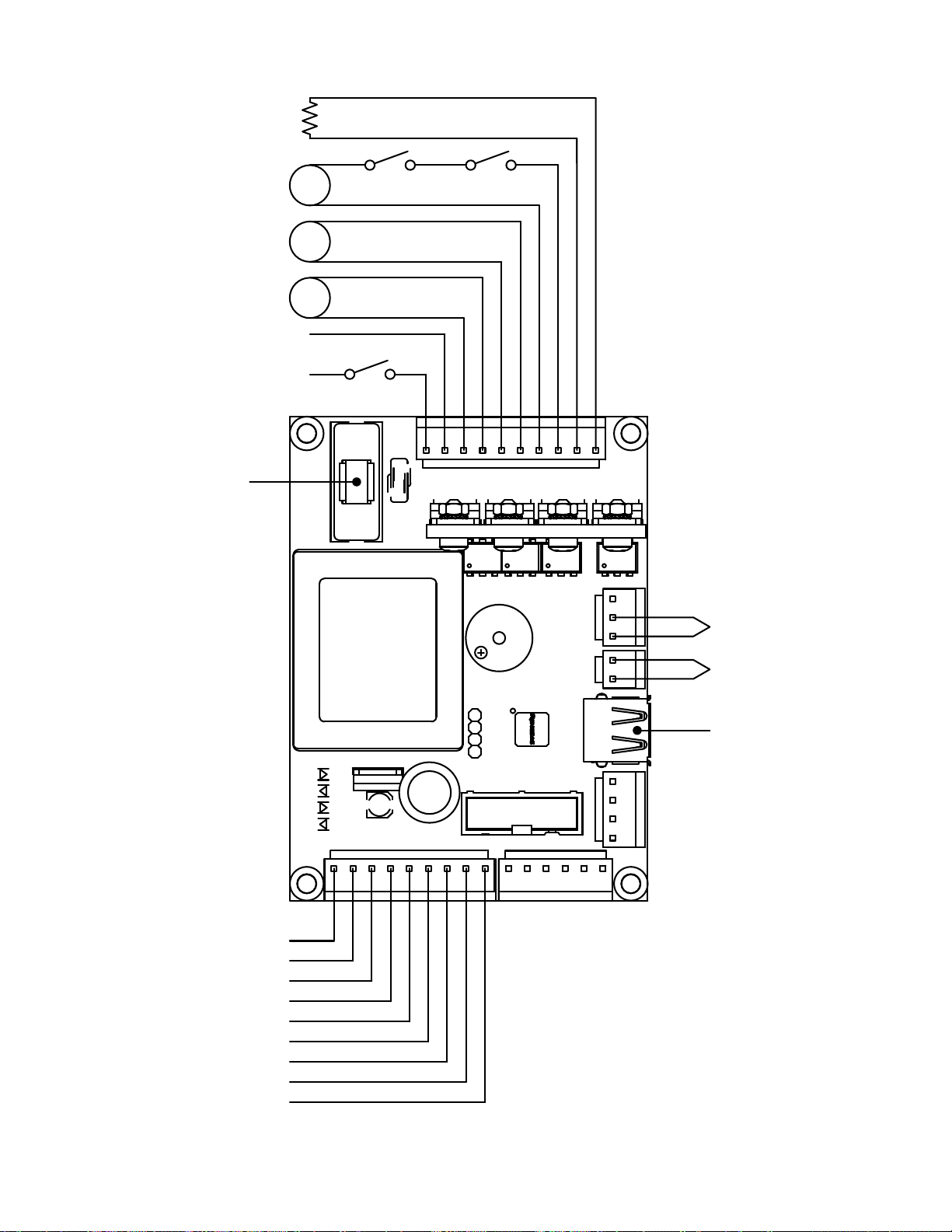
7077-801D • September 17, 2019
(877) 477- 4768
38
M
M
M
110 V
LINE
NEUTRAL
IGNITER
FEED MOTOR
EXHAUST
BLOWER
CONVECTION
BLOWER
VACUUM
SWITCH
HOPPER
SWITCH
AMBIENT
TEMPERATURE
EXHAUST
TEMPERATURE
SERIAL PORT
(SERVICE ONLY)
BLACK
WHITE
PURPLE
PURPLE
BLUE
BLUE
WHITE
RED
BLACK
BLACK
POT SET TEMP VCC
POT SET TEMP GND
POT SET TEMP SIG
POT FEED ADJUST VCC
POT FEED ADJUST GND
POT FEED ADJUTS SIG
LED RED
LED AMBER
LED GREEN
FUSE
SNAP
DISC
B. Wiring Diagram
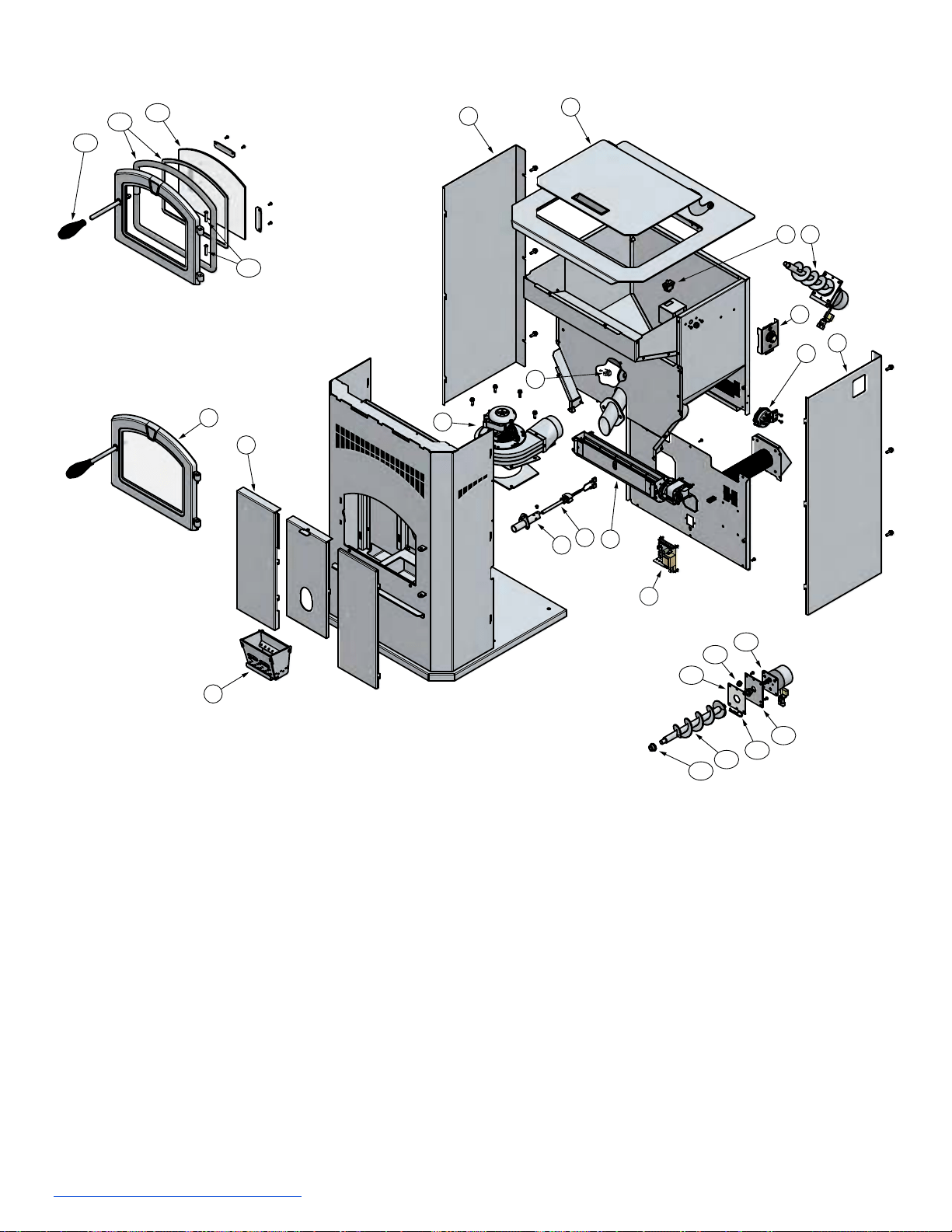
7077-801D • September 17, 2019
39
1
2
5
4
8
6
7
10
9
3
11
10
2
10
12
12.1
12.2
12.3
12.5
12.4
12.7
12.6
3.1
3.2
3.3
3.1
13
1. Hopper Lid (1 per unit)*
2. Side Panels (2 per unit)*
3. Front Door Assembly
3.1 Spring handle and hinge pins
3.2 Door Rope Gasket and Glass Tape
3.3 5mm Ceramic Glass
4. Baes (3 per unit)*
5. Firepot
6. Convection Blower
7. Igniter
8. Igniter Chamber
9. Exhaust Blower
10. Snap Disk, Vacuum Switch, Hopper
Switch
11. Dial Control
C. Replacement Parts
12. Feed Assembly
12.1 Bronze Bushings (2 per unit)
12.2 Auger Assembly
12.3 Feed Motor Hitch Pin
12.4 Feed Motor Bracket
12.5 Feed Motor Gasket
12.6 Rubber Grommet
12.7 Feed Motor
13. Control Board*
14. Exhaust Probe (not pictured)
15. Ambient Probe (not pictured)
*WHEN ORDERING REPLACEMENT
PARTS, SPECIFY MODEL TO GET THE
CORRECT PARTS.
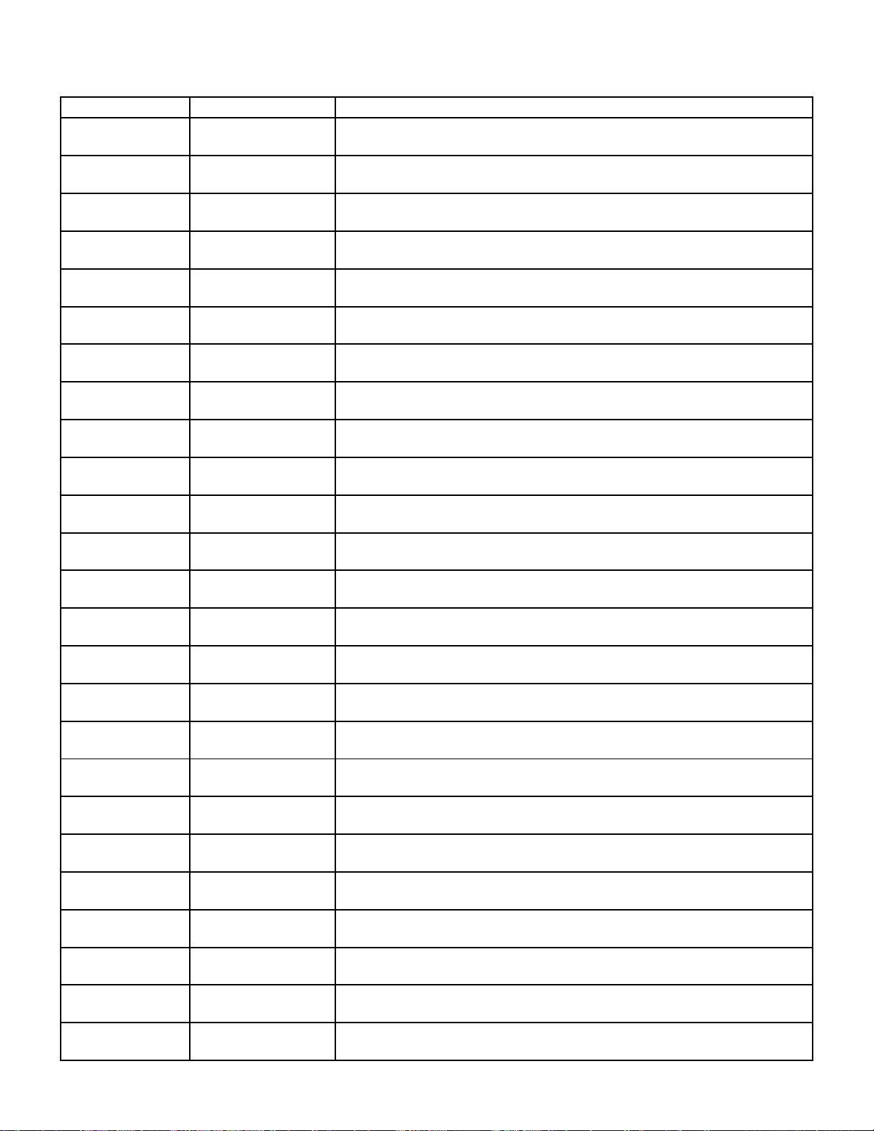
7077-801D • September 17, 2019
(877) 477- 4768
40
D. Service & Maintenance Log
Date of Service Performed By Description of Service

7077-801D • September 17, 2019
41
Doors with Glass and Plated Parts
Glass is warranted against thermal breakage only
. To clean glass, use a
ceramic/glass cleaner or polish. Do not use ammonia based cleaners. A
suitable cleaner is available at your nearest Pleasant Hearth dealer. DO NOT
CLEAN GLASS WHILE HOT AND DO NOT USE ABRASIVE
CLEANERS.
Plated parts will not be covered under this warranty. Plated parts should be
cleaned by using denatured alcohol only and rubbed lightly with a lint-free
non-abrasive cloth. Excessive rubbing or polishing may remove the plated
nish. Plated parts may also be damaged by external chemicals.
Further Exclusions
WOOD-BURNING STOVE
Electrical components, such as the blower, are covered for ve (5) years from
the date of purchase if they are included with the purchase of your stove.
This warranty will not include or extend to paint, gaskets or rebrick
components, and does not cover any removable rebox components such as
brick retainers or stainless steel air tubes.
PELLET-BURNING STOVE:
Five Year Period:
1. Carbon steel and welded seams in the rebox are covered for ve (5)
years against splitting.
2. The steel door and hinges are covered for ve (5) years against cracking.
One Year Period:
1. Component parts such as the hopper, auger, burn-pot, bafe plate,
auger shaft and fasteners are covered for one (1) year against cracking,
breakage and welded seam separation.
2. Electrical components, accessory items, glass and the painted surface of
the stove are covered for one (1) year from the date of purchase.
IF WARRANTY SERVICE IS REQUIRED
Contact GHP Group Customer Service. Make sure you have your sales receipt
and the model/serial number of your GHP Group product.
Do not attempt to do any service work yourself, unless pre-approved by GHP
Group in writing as this will void the warranty.
GHP Group must authorize service and provide a Warranty Claim Number prior
to any warranty related service calls. Without an authorization number, any
service work will not be deemed warranty.
IMPORTANT NOTICE
BEFORE LIGHTING YOUR FIRST FIRE, REMOVE PLASTIC FILM OFF TRIM
AND CLEAN THE PLATED SURFACES WITH DENATURED ALCOHOL OR A
GOOD QUALITY, NON-ABRASIVE LIQUID GLASS CLEANER. APPLY WITH A
VERY SOFT, CLEAN CLOTH. DO NOT USE PAPER TOWELS TO CLEAN THE
PLATED PARTS. FAILURE TO CLEAN ALL MARKS AND FINGERPRINTS
FROM THE PLATED SURFACES WILL CAUSE PERMANENT DAMAGE.
NOTE: Some states and provinces do not allow the exclusion or limitation of
incidental or consequential damages. The above limitations may not
apply to you.
GHP Group, Inc. • 6440 W. Howard St. • Niles, IL 60714
KEEP THIS WARRANTY
Serial #_________________________ Model #______________
Date Purchased________________________
GHP Group warrants that your new wood-burning stove, pellet-burning stove,
or masonry wood insert is free from manufacturing and material defects for a
period of ve years from the date of sale, subject to the following conditions
and limitations.
1. This warranty is extended to the original owner only, for residential use,
and is subject to proof of purchase.
2. The new GHP Group product must be installed and operated at all times
in accordance with the installation and operation instructions supplied
with the appliance, and installation must be to local and national codes.
Any alterations, willful abuse, accident, over ring or misuse will not be
covered under warranty.
NOTE: Some minor movement of certain parts is normal and is not a defect
and therefore, not covered under warranty.
3. The warranty is non-transferable, and is made to the original owner,
provided that the purchase was made through an authorized GHP Group
supplier. The serial number must be supplied along with the Bill of Sale,
showing the date of purchase, at the time the claim is submitted.
4. This warranty is limited to the repair or replacement of parts only, found
to be defective in material or construction, provided that such parts have
been subjected to normal conditions of use and service, after a said defect
has been conrmed by GHP Group, or an authorized representative’s
inspection. Defective parts must be shipped back (at GHP Group
discretion), transportation prepaid, to the manufacturer. Credits will be
issued upon receipt of return of the defective product to GHP Group.
5. GHP Group, at its discretion, can fully discharge all obligation with respect
to this warranty by refunding the wholesale price of the defective part(s).
6. Any installation, labor, construction, transportation or other related costs
or expenses arising from defective parts, repair, replacement or otherwise
of same, will not be covered by this warranty nor will GHP Group assume
responsibility for same. Further, GHP Group will not be responsible for any
incidental, indirect or consequent damages, except as provided by law,
and in no event shall they exceed the original purchase price.
7. All other warranties - expressed or implied - with respect to the product, its
components and accessories, or any obligations/liabilities on the part of
GHP Group are hereby expressly excluded.
8. GHP Group neither assumes, nor authorizes any third party to assume,
on GHP Group’s behalf, any other liabilities with respect to the sale of this
GHP Group product.
9. The warranties as outlined within this document do not apply to chimney
components or other products made by other manufacturers when used
in conjunction with the installation of this product. Improper use or the
use of non-approved components may nullify your warranty. If in doubt,
contact your nearest GHP Group supplier or GHP Group Customer
Service Department.
10. GHP Group will not be responsible for:
• Downdrafts or spillage caused by environmental conditions such
as nearby trees, buildings, rooftops, hills, mountains, or ineffective
chimney design.
• Inadequate ventilation, excessive offsets or negative air pressure
caused by mechanical systems such as furnaces, clothes dryers,
fans, etc.
11. This warranty is void if:
• The appliance has been operated in atmospheres contaminated by
chlorine, uorine, or other damaging chemicals.
• This appliance has been subjected to prolonged periods of
dampness or condensation.
• The appliance has any damage due to water, or weather damage
that is the result of, but not limited to, improper chimney/venting
installation.
• The appliance has been subjected to will full or accidental abuse
or misuse.
• Corrosive driftwood, manufactured logs or other fuels are used other
than as outlined in the installation and operating instructions.
• The appliance is not maintained in good condition, including rebrick
and gaskets.
E. 5 Year Warranty
7077-801D • September 17, 2019
(877) 477- 4768
42
Date purchased/installed: _________________________________________
Serial Number: ______________________________________ Location on appliance: ________________________
Store purchased from: ________________________________ Store Location: ______________________________
Notes: _________________________________________________________________________________________
______________________________________________________________________________________________
______________________________________________________________________________________________
We recommend that you record the following pertinent
information for your GHP Group Pellet Stove
Please contact the GHP Group with any questions or concerns.
www.ghpgroupinc.com
For Customer Service 1-877-447-4768
Prior to calling, please have the model, serial number, and sales receipt of the unit you are calling about.
This information can be found at the rear of the unit.
CONTACT INFORMATION:
Manufactured for GHP at
ClearWater Metals
Lot CN2, Mai Trung IZ, Ben Cat Town,
Binh Duong Providence, Vietnam
Made in Vietnam
6440 W. Howard St.
Niles, IL 60714
877-447-4768