
1
255895
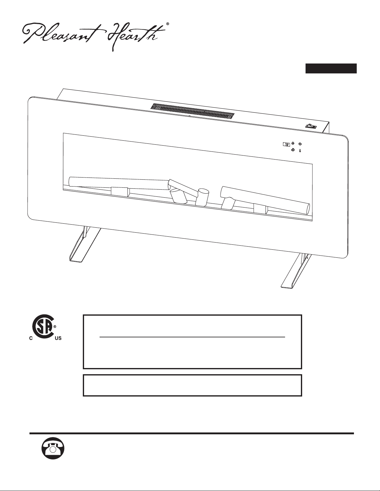
Questions, problems, missing parts? Before returning to your retailer, call our
customer service department at 1-877-447-4768, 8:00 a.m. – 4:30 p.m. CST,
Monday – Friday.
INSTALLER: Leave this manual with the appliance.
CONSUMER: Retain this manual for future reference.
WARNING!
IF THE INFORMATION IN THIS MANUAL IS NOT FOLLOWED EXACTLY,
AN ELECTRICAL SHOCK OR FIRE MAY RESULT
CAUSING PROPERTY DAMAGE, PERSONAL INJURY OR LOSS OF LIFE.
IMPORTANT INSTRUCTIONS
PLEASE READ THIS MANUAL BEFORE INSTALLING AND USING APPLIANCE
ATTACH YOUR RECEIPT HERE
Serial Number ________________________________ Purchase Date _________________________________
Español p. 19
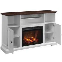
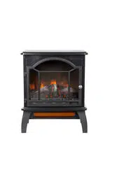
ELECTRIC FIREPLACE
MODEL # 311-42-10
210607
2
IMPORTANT: Read all instructions and warnings carefully before starting installation.
Failure to follow these instructions may result in a possible electric shock, injury to
persons, fire hazard and will void the warranty.
Please read the Installation & Operating Instructions before using this appliance.
TABLE OF CONTENTS
Safety Information ............................................................................................................................3
Package Contents ............................................................................................................................5
Fireplace Dimensions ......................................................................................................................6
Preparation ...................................................................................................................................... 7
Electrical Connection .......................................................................................................................4
Grounding Instructions .....................................................................................................................4
Remote Control ...............................................................................................................................7
Assembly Instructions .....................................................................................................................7
Pre-Installation ................................................................................................................................7
Installation: Wall Mount ...................................................................................................................7
Installation: Table Top ......................................................................................................................7
Operating Instructions ......................................................................................................................8
Care and Maintenance .....................................................................................................................9
Circuit Diagram ...............................................................................................................................10
Service Parts ..................................................................................................................................13
Troubleshooting ..............................................................................................................................11
Warranty .........................................................................................................................................12
PRODUCT DAMAGE MAY OCCUR.
Never attempt to disassemble or alter the product in any way not instructed by this manual.
CAUTION

3
1. Read all instructions before using this replace.
2. Always unplug this appliance when not in use.
3. Children should be advised not to play with this replace.
4. Do not operate any heater with a damaged cord or plug or after the heater malfunctions, has been
dropped or damaged in any manner. Return heater to authorized service facility for examination,
electrical or mechanical adjustment, or repair.
5. Any repairs to this appliance should be carried out by qualied/authorized service personnel only.
6. Under no circumstances should this appliance be modied. Parts having to be removed for
servicing must be replaced with original “OEM” (original equipment manufacturers) parts only.
7. Do not use outdoors.
8. This appliance is not intended for use in bathrooms, laundry areas, and similar indoor locations.
Never locate this appliance where it may fall into a bathtub or other water container.
9. Do not run the cord under carpeting. Do not cover the cord with throw rugs, runners, or the like.
Arrange the cord away from trafc areas and where it will not be tripped over.
10. To disconnect heater, turn controls to off, then remove plug from outlet.
11. Connect to properly grounded outlets only.
12. This appliance, when installed, must be electrically grounded in accordance with local codes, with
the current CSA C22.1 Canadian Electric codes, or for USA installations, follow local codes and the
National Electrical Code, ANSI/NFPA No. 70.
13. There is a thermostat limiter inside the replace. When the inner temperature over heats or
abnormal heating occurs, the thermostat protective device will cut off power supply to avoid
damage to the replace or risk of re.
14. This appliance has hot and arching or sparking parts inside. Do not use it in areas where gasoline,
paint, or ammable liquids are used or stored. This appliance should not be used as a drying rack
for clothing, nor should Christmas stockings or decorations be hung on or near it.
15. Use this appliance only as described in this manual. Any other use not recommended by the
manufacturer may cause re, electric shock, or injury to persons.
16. The use of an extension cord is not recommended due risk of re. If used the extension cord shall
be No. 14 AWG minimum size and rated no less than 1875 watts, and the extension cord shall be a
three-wire cord with grounding type plug and cord connector. The extension cord shall not be more
than 20 ft (6 m) in length.
17. Do not use this appliance with a programmable timer or any other device that switches the
appliance on and off automatically. In order to avoid a hazard due to inadvertent resetting of the
thermal cut out, this appliance must not be supplied through an external switching device, such as
a timer, or connected to a circuit that is regularly switched on and off by an utility.
18. This product contains a button battery. If swallowed, it could cause severe injury or death in just 2
hours. Seek medical attention immediately.
Please read and understand this entire manual before attempting to assemble, operate or install the product.
SAFETY INFORMATION SAVE THESE INSTRUCTIONS
4
SAFETY INFORMATION (CONTINUED)
CAUTION: Operate only on supplied stand or mount to wall. Do Not install heater less
than 60 cm/23.6 in from the oor.
CAUTION: Do not insert or allow foreign objects to enter any ventilation or exhaust
openings, as this may cause an electric shock or re, or damage to the heater.
CAUTION: When using electrical appliances, basic precautions should always be
followed to reduce the risk of re, electrical shock, and injury to persons.
IMPORTANT: SAVE THESE INSTRUCTIONS.
WARNING: This heater is hot when in use. To avoid burns, do not let bare skin touch
hot surfaces. If provided, use handles when moving this appliance. Keep combustible
materials, such as furniture, pillows, bedding, papers, clothes, and curtains at least
3 feet (0.9 m) from front, sides and rear of the heater.
WARNING: This Product can expose you to chemicals including Diisononyl phthalate
(DINP) which is known to the State of California to cause cancer and Di-isodecyl
phthalates (DIDP) which is known to the State of California to cause birth defects or
other reproductive harm. For more information go to www.p65Warnings.ca.gov
CAUTION: Extreme caution is necessary when any heater is used by or near children or
invalids, and whenever the heater is left operating and unattended.
CAUTION: To prevent a possible re, do not block heater air intakes or the exhaust in
any manner. Do not operate the heater on soft surfaces, like a bed, where openings may
become blocked.
5
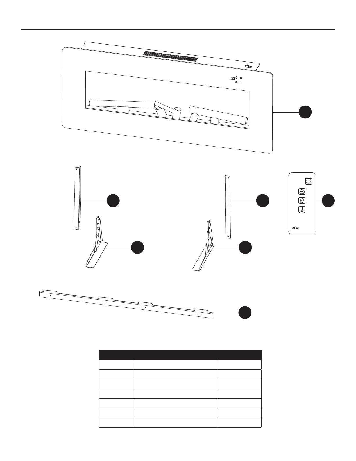
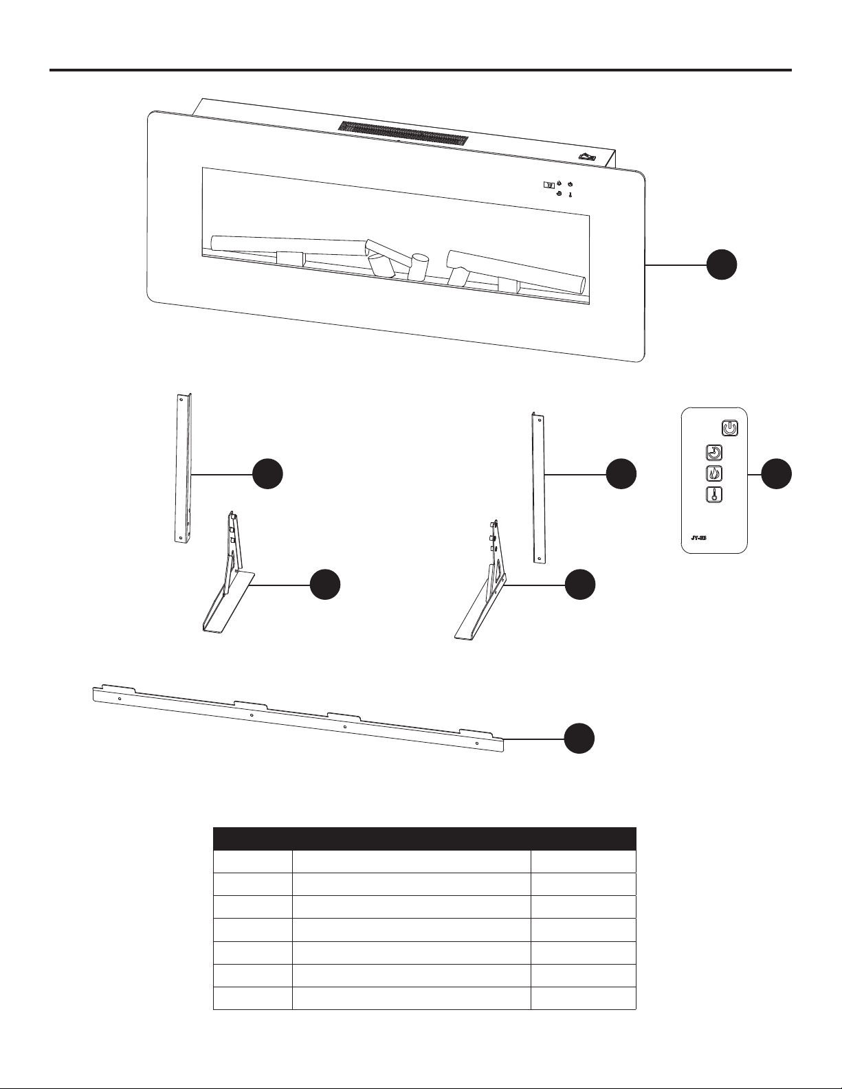
PART DESCRIPTION QUANTITY
A Electric Firebox 1
B Remote Control 1
C Wall Mounting Bracket 1
D Right Foot Bracket 1
E Right Foot Base 1
F Left Foot Bracket 1
G Left Foot Base 1
PACKAGE CONTENTS
A
DG
F E
C
B
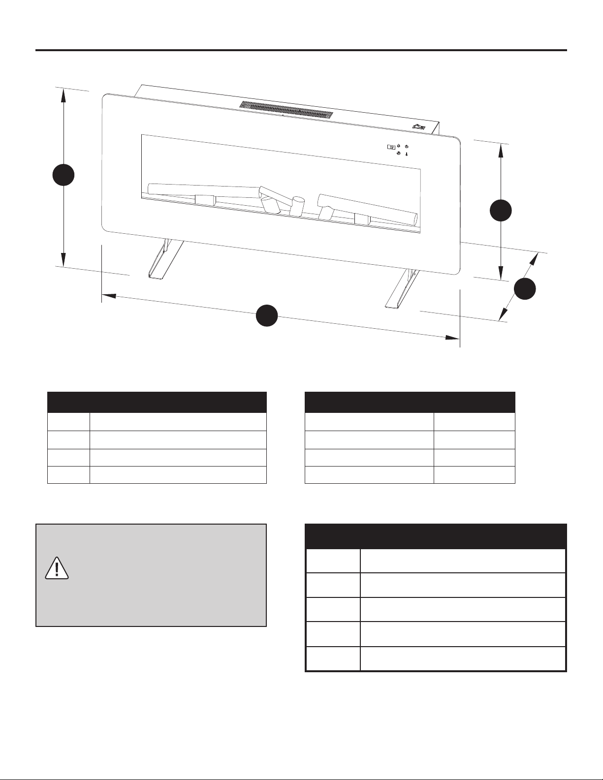
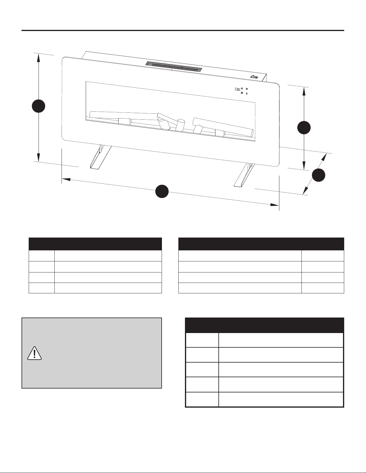
6
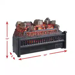
REF. 311-42-10
A 10.5 in.
B 21 in.with base
C 17.3 in. without base
D 42 in.
TECHNICAL SPECIFICATIONS
Voltage 120V AC
Frequency 60HZ
Amps 11.7A
Rating 1400W
FIREPLACE DIMENSIONS
CLEARANCE TO COMBUSTIBLES
Sides 4 in. (101.6 mm)
Floor 0 in. (0 mm)
Top 36 in. (914 mm)
Front 36 in. (914 mm)
Rear 0 in. (0 mm)
B
C
A
D
WARNING: Keep combustible
materials, such as furniture,
pillows, bedding, papers, clothes,
and curtains at least 3 feet (0.9 m)
from front, sides and rear of the
heater.
7
Planning Installation
Before you begin assembly, locate the instructions and hardware. Compare all parts with the
Hardware Included and Package Contents lists. Be sure you have all the parts and can identify them.
A helping hand is always good. Assemble your replace with an adult assistant if possible.
Some pieces are heavy and will need to be held by a helper. Assembly time will take approximately
5-20 minutes.
Before assembly, use scissors to unwrap the parts from the packaging. Do not use a box cutter or
exacto-knife, as you may cut into the heater pieces inside the box and damage the nish. Check
for the hardware bag located inside the packaging, taped to the top of the box. Do not discard any
pieces. Use an appropriate screwdriver to insert and tighten all screws.
Electrical Connection
Grounding Instructions
A 15 Amp, 120 Volt, 60 Hz circuit with a properly grounded outlet is required to operate this
appliance. Preferably, the appliance will be on a dedicated circuit, as other appliances on the same
circuit may cause the circuit breaker to trip or the fuse to blow when the replace is in operation.
The unit comes standard with a 6 ft (1.8 m) long 3-wire cord, exiting out the back of the replace.
Plan the installation to avoid the use of an extension cord. If an extension cord must be used, it must
be a minimum No. 14 AWG, 3-wire with grounding type plug and connector, and must be rated not
less than 1875 watts. The extension cord shall not be more than 20 ft (6 m) in length.
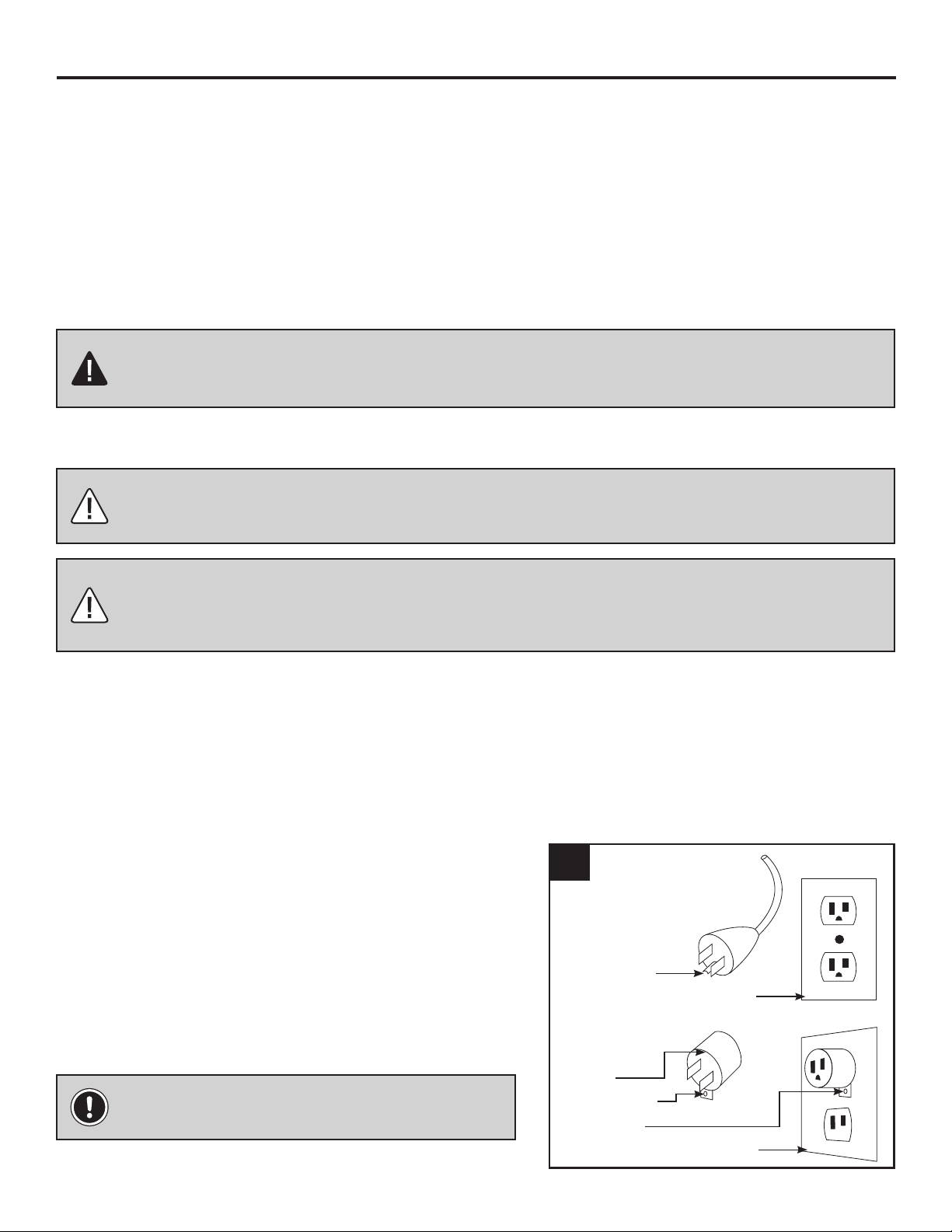
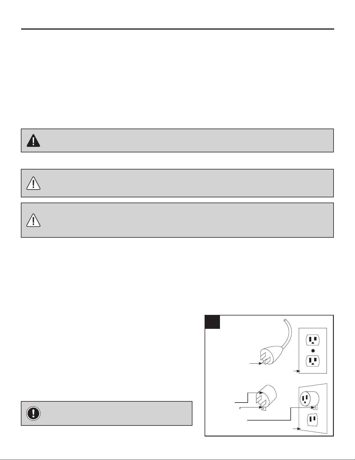
This heater is for use with 120 volts. The cord has
a plug as shown at (A) in Figure 1. An adapter as
shown at (C) is available for connecting three-blade
grounding-type plugs to two-slot receptacles. The
green grounding lug extending from the adapter
must be connected to a permanent ground such as
a properly grounded outlet box. The adapter should
not be used if a three-slot grounded receptacle is
available.
PREPARATION
CAUTION: This carton includes a GLASS panel! Always use extreme caution when
handling glass. Failure to do so could result in personal injury or property damage.
WARNING: Electrical outlet wiring must comply with local building codes and other
applicable regulations to reduce the risk of re, electrical shock, and injury to persons.
WARNING: Do not use this replace if any part of it has been under water. Immediately
call a qualied service technician to inspect the replace and replace any part of the
electrical system which has been under water.
Grounding Pin
Cover of Grounded Outlet Box
Adapter
Grounding Lug
Metal Screw
Cover of Grounded Outlet Box
A
B
C
NOTE: Adapters are NOT for use in Canada.
1
8
PRE-INSTALLATION
This Class (B) device complies with Part 15 of the FCC Rules and Canadian ICES-003. Operation is
subject to the following two conditions:
(1) This device may not cause harmful interference, and (2) this device must accept any interference
received, including interference that may cause undesired operation. There is no guarantee that
interference will not occur in a particular installation. If this equipment does cause harmful
interference to radio or television reception, which can be determined by turning the equipment off
and on, the user is encouraged to try to correct the interference by one ore more of the following
measures:
• Reorient or relocate the receiving antenna.
• Increase the separation between the equipment and receiver.
• Connect the equipment into an outlet on a circuit different from that to which the receiver is
connected.
• Consult the dealer or an experienced radio/TV technician for help.
This remote control requires 1 Lithium Coin Cell Battery (size CR2025), which is included.
REMOTE CONTROL
CAUTION: Changes or modications to this unit not expressly approved by the party
responsible for compliance could void the user’s authority to operate the equipment.
WARNING: DO NOT mix old and new batteries.
DO NOT use re chargeable silver oxide cell batteries with remote control unit.
DO NOT mix alkaline, standard (Carbon-Zinc), or rechargeable (Nickel-Cadmium) batteries.
DO NOT dispose of batteries in re. Improper disposal may cause batteries to leak or explode.
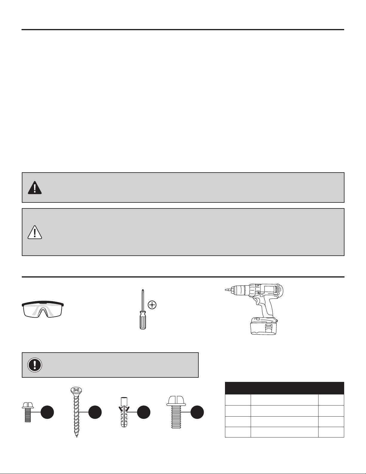
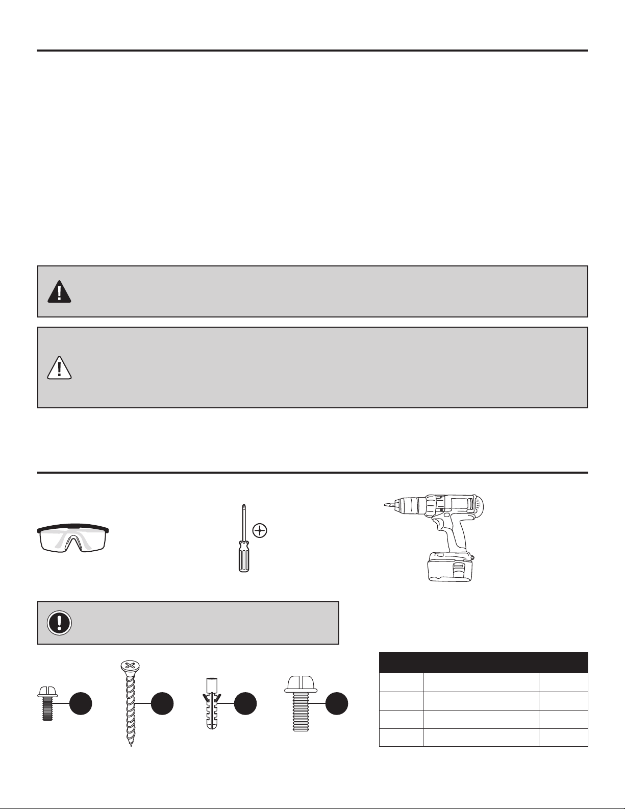
Tools Required (not included)
Safety Goggles Phillips Screwdriver Power Drill
Hardware Included
NOTE: Hardware shown not actual size.
AA BB CC DD
Part Description Qty.
AA Small Bolt 4
BB Large Wall Screw 4
CC Wall Anchor 4
DD Large Bolt 6

9
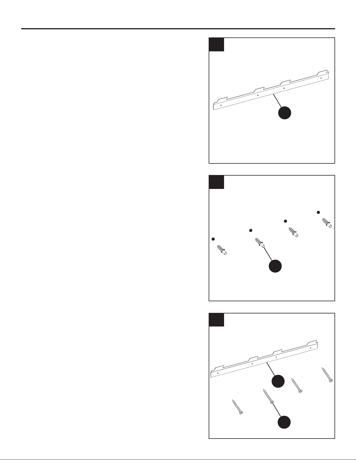
C
CC
BB
C
1. Choose a solid wall. Position the mounting bracket
(C) where the electric rebox (A) is to be installed
on the wall, and ensure that the mounting bracket
(C) is level.
Use a pen to mark the 4 mounting holes on the
wall at the desired mounting location, using the
mounting bracket (C) as a template.
2. Insert the 4 self-drilling wall anchors (CC) into
the wall where previously marked. If installing the
mounting bracket (C) to a wall stud, there is no
need to drill the holes in the wood and no need for
the plastic wall anchors (CC). It is recommended
to install the mounting bracket to at least one stud.
3. Secure the mounting bracket (C) to the wall using
4 large screws (BB).
1
2
3
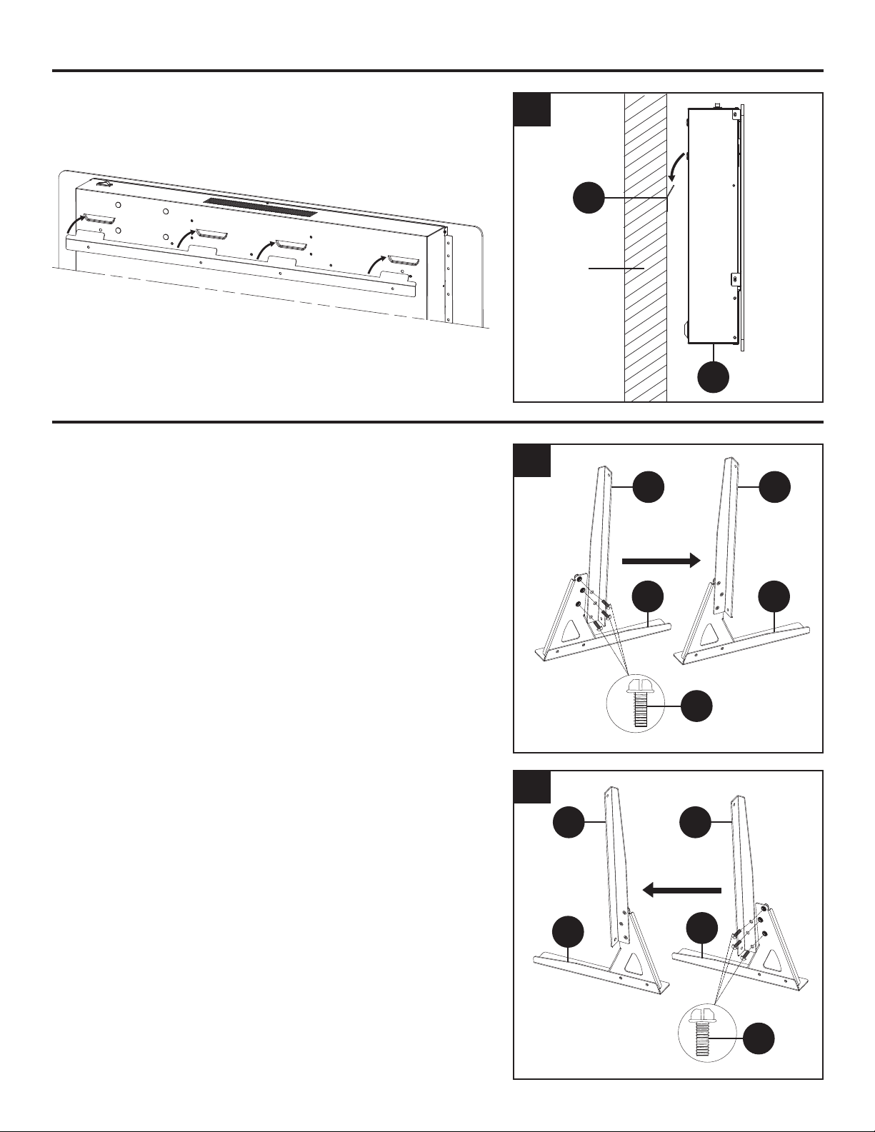
INSTALLATION: WALL MOUNT
10
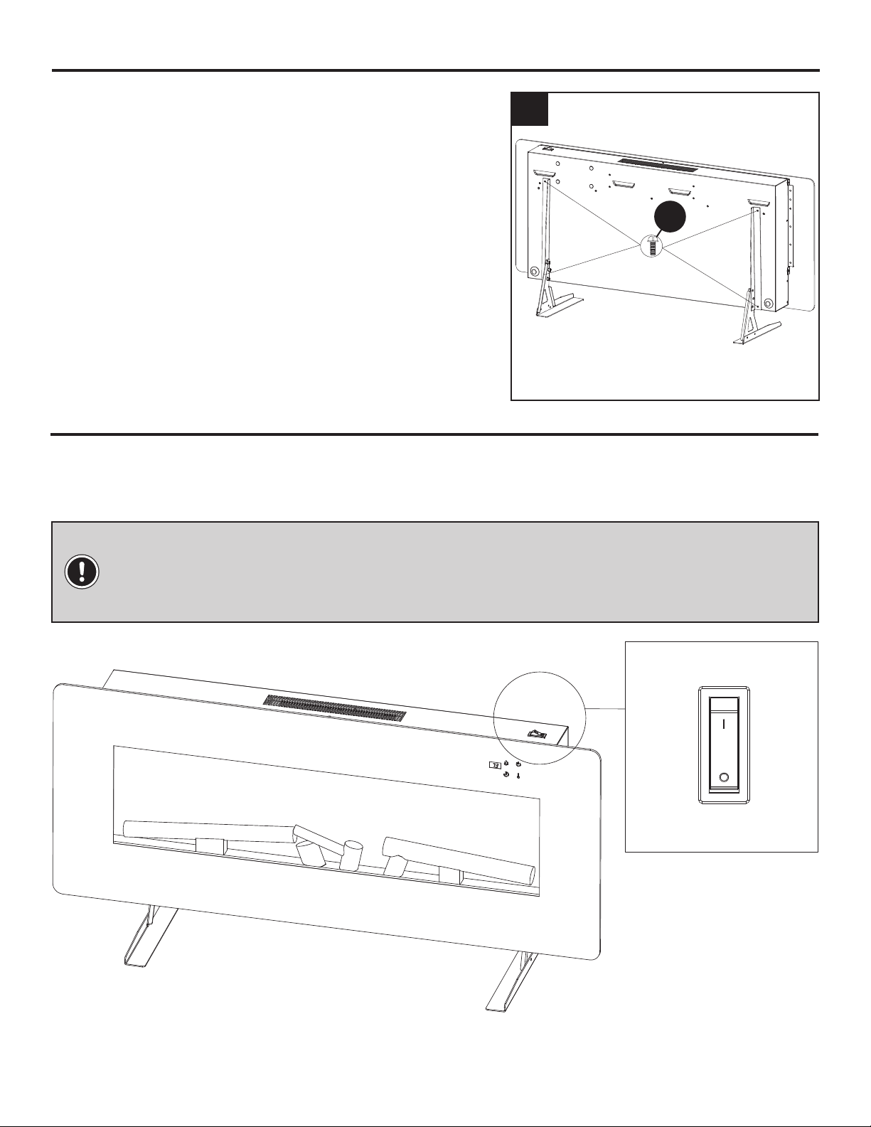
4. Hang the electric rebox (A) on the mounting
bracket (C).
1. Attach the left bracket (G) to the feet Left base (F)
using 3 large screws (DD).
2. Attach the Right bracket (D) to the feet Right base
(E) using 3 large screws (DD).
4
1
2
INSTALLATION: WALL MOUNT (CONTINUED)
INSTALLATION: TABLE TOP
C
A
Wall
DD
G
D D
G
F
E
E
F
DD

11
Disable Heater
Calefacción deshabilitada
Enable Heater
Calefacción habilitada
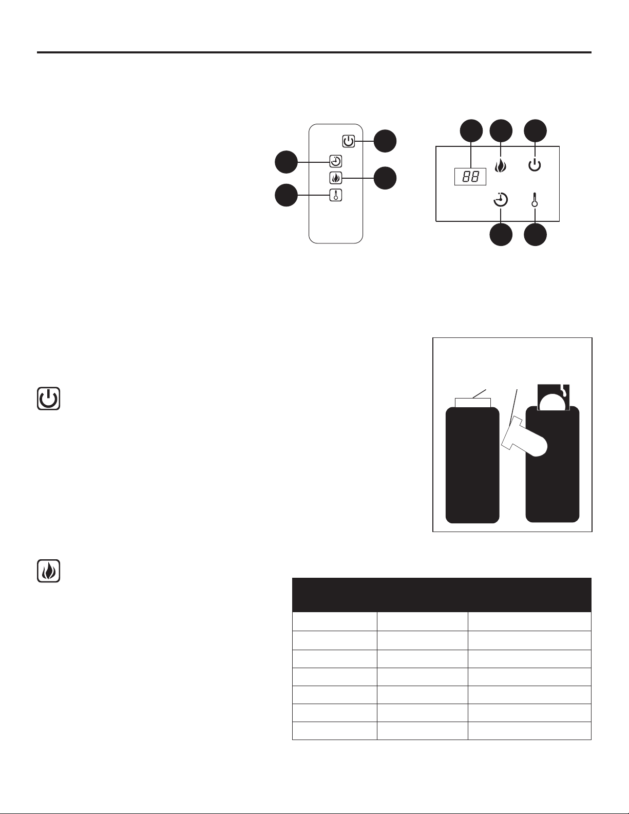
3. Use a screwdriver to secure the mounting rebox
(A) to the left and right table top stand with 4 small
screws (AA).
3
INSTALLATION: TABLE TOP (CONTINUED)
Read All Instructions Before Use
Figure 2
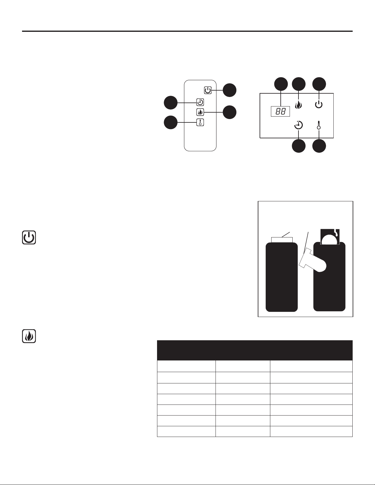
Check that the heater outlet grill is not covered or obstructed in anyway, and make sure the power to
the unit is switched on.
OPERATING INSTRUCTIONS
NOTE: This unit comes equipped with a switch on the top panel which disables the
heater (See Figure 2). To enable the heater, please ensure the switch is in the "On" mode.
The heater will function using the remote control or control panel on the front of the unit.
AA
12
OPERATING INSTRUCTIONS (CONTINUED)
Using the Manual and Remote Controls
Using the Power Button
Using the Flame Control Button
On the top-right side of the electric replace (A) is the control panel. The buttons on the front of the
electric replace (A) and the remote control (B) function in the same way. The remote control has an
effective range of up to 13 ft.
• The main power button (1) is located on the
control panel on the front of the electric replace.
• Pressing the power button (1) once turns the
power on.
• Pressing the power button (1) again will turn the
power off.
• If you nd that none of the other buttons appear
to work, check to make sure that the main power
(1) is turned on.
• Press the ame control button (2)
to turn on the ember bed and
ame effect.
• Pressing the ame control button (2)
once turns ames on and lights the
ember bed.
• Pressing the ame control button
(2) again will cycle through different
colors of the ember bed. The color
rotation mode will cycle through
different color settings continuously.
Reference the table for more
detailed information.
Check that the heater outlet grill is not covered or obstructed in any way, and make sure the power
to the unit is switched on. The replace can be accessed in two ways: Using the touchpad control
panel, or using the multifunction remote control unit.
Press the appropriate button to operate your replace:
1. Power Button
2. Flame Control Button
3. Heater Control Button
4. Timer Control Button
5. Digital Display Panel
JY-3B
JY-3B
1
2
4
1
3
5
2
4
3
The plastic tab inside the battery
compartment MUST be removed
before the remote control will operate.
(Pull Tab)
Button Press Display Value
Ember Bed and
Flame Color
1st Press 1 Orange
2nd Press 2 Green
3rd Press 3 Blue
4th Press 4 Orange/Green
5th Press 5 Orange/Blue
6th Press 6 Orange/Green/Blue
7th Press 7 Cycle
13
OPERATING INSTRUCTIONS (CONTINUED)
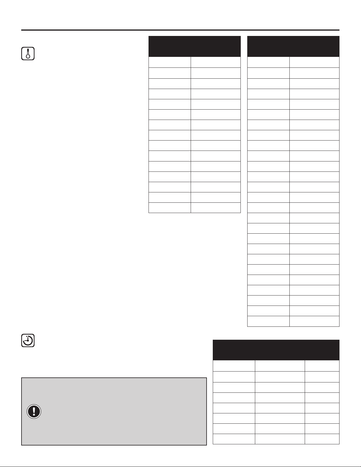
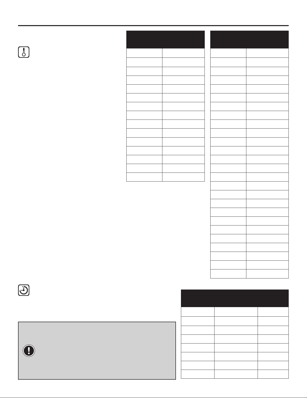
Using the Heater Control Button
Using the Timer Control Button
This button controls the heater
ON/OFF. When the temperature
unit is set as “F” or “C”, the
temperature scope is as shown
in the table.
To display the temperature
setting in either Fahrenheit or
Celsius, press the heat button
(3) of control panel once, then
press and hold the heater
button (3) of control panel for
10 seconds. The display will
switch between Fahrenheit or
Celsius.
Pressing the timer control button (4) will set the
timer. This interval period is shown in the display
(5) on the control panel on the front of the electric
replace. The set intervals are as listed in the table.
NOTE: If this product experiences exceptionally
high temperature, it may automatically stop
heating. If this occurs the product should be
unplugged or isolated from the main supply for
a period of 5 minutes before the power is then
resupplied.
Button
Press
Celsius
Temperature
1st Press 17 ˚C
2nd Press 18 ˚C
3rd Press 19 ˚C
4th Press 20 ˚C
5th Press 21 ˚C
6th Press 22 ˚C
7th Press 23 ˚C
8th Press 24 ˚C
9th Press 25 ˚C
10th Press 26 ˚C
11th Press 27 ˚C
12th Press 28 ˚C
13th Press 29 ˚C
14th Press 30 ˚C
15th Press ON
Button
Press
Timer
Interval
Display
Value
1st Press 1 Hour 1H
2nd Press 2 Hours 2H
3rd Press 3 Hours 3H
4th Press 4 Hours 4H
5th Press 5 Hours 5H
6th Press 6 Hours 6H
7th Press 7 Hours 7H
8th Press 8 Hours 8H
Button
Press
Fahrenheit
Temperature
1st Press 62 ˚F
2nd Press 63 ˚F
3rd Press 64 ˚F
4th Press 65 ˚F
5th Press 66 ˚F
6th Press 67 ˚F
7th Press 68 ˚F
8th Press 69 ˚F
9th Press 70 ˚F
10th Press 71 ˚F
11th Press 72 ˚F
12th Press 73 ˚F
13th Press 74 ˚F
14th Press 75 ˚F
15th Press 76 ˚F
16th Press 77 ˚F
17th Press 78 ˚F
18th Press 79 ˚F
19th Press 80 ˚F
20th Press 81 ˚F
21st Press 82 ˚F
22nd Press 83 ˚F
23rd Press 84 ˚F
24th Press 85 ˚F
25th Press 86 ˚F
26th Press ON
14
To turn off heat mode, press and hold the power button for 10 seconds to enter heat lock out
mode. Flame lights will ash 6 times to signal the heat function is turned off and locked out. To
turn on heat mode, press and hold the power button for 10 seconds. The ame lights will ash
6 times and the heat function will be restored. When the heat button is pressed in lock out
mode, the ember bed will ash 6 times until the heating mode is turned on.
OPERATING INSTRUCTIONS (CONTINUED)
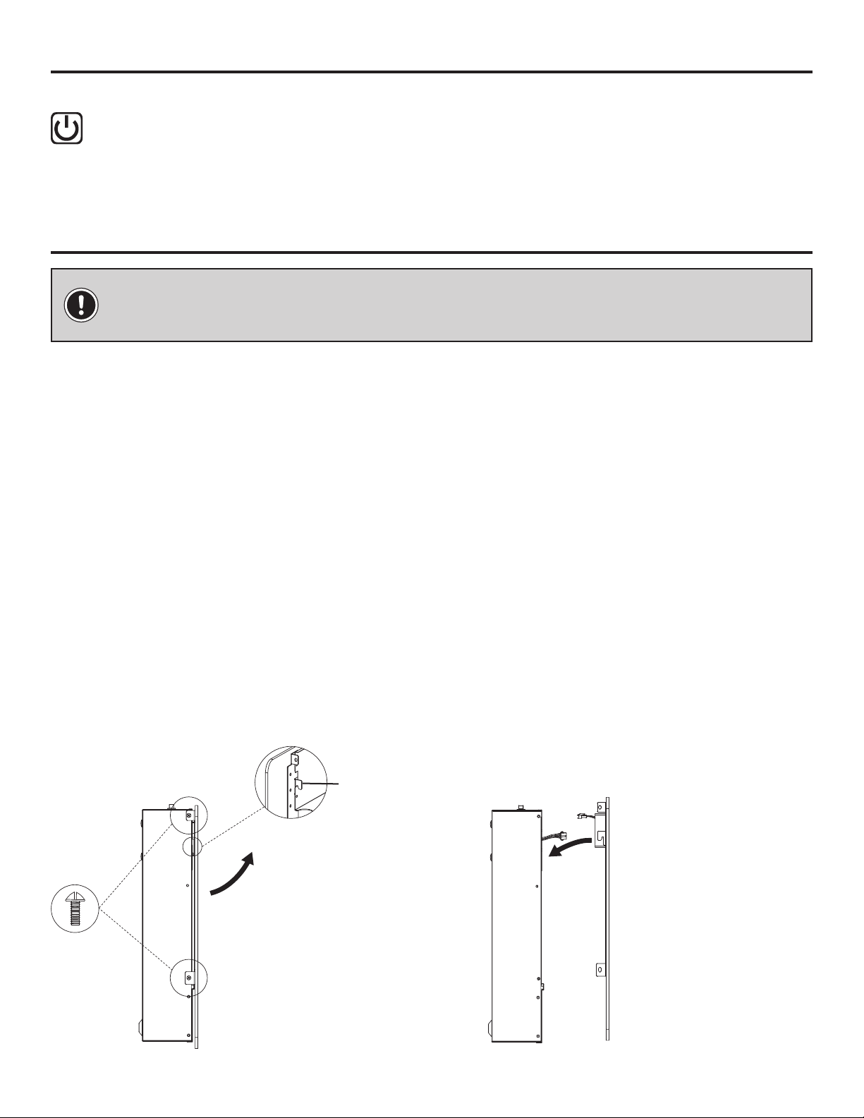
CARE AND MAINTENANCE
Heater Locking Function
IMPORTANT: Always unplug the power cord before cleaning the unit. Allow the unit to
cool before cleaning it.
• Wipe the exterior surface of the electric rebox occasionally with a soft, damp cloth (not dripping
wet), and dry the exterior surface before operating.
• Do not immerse the electric replace in water.
• Do not use any cleaning chemicals such as detergents and abrasives.
• Do not allow the interior to get wet, as this could create a hazard.
• Light accumulated dust may be removed from the electric replace with a soft, dry cloth.
• To store the electric replace, put it back into its original packaging and store in a clean, dry place.
• The blower and ame motor are pre-lubricated for a durable using time and need no further
lubrication or maintenance. Dust particles will accumulate on/in the electric replace, so periodic
cleaning/vacuuming of the electric replace is recommended.
• Always turn the heater OFF and unplug the power cord from the outlet before cleaning.
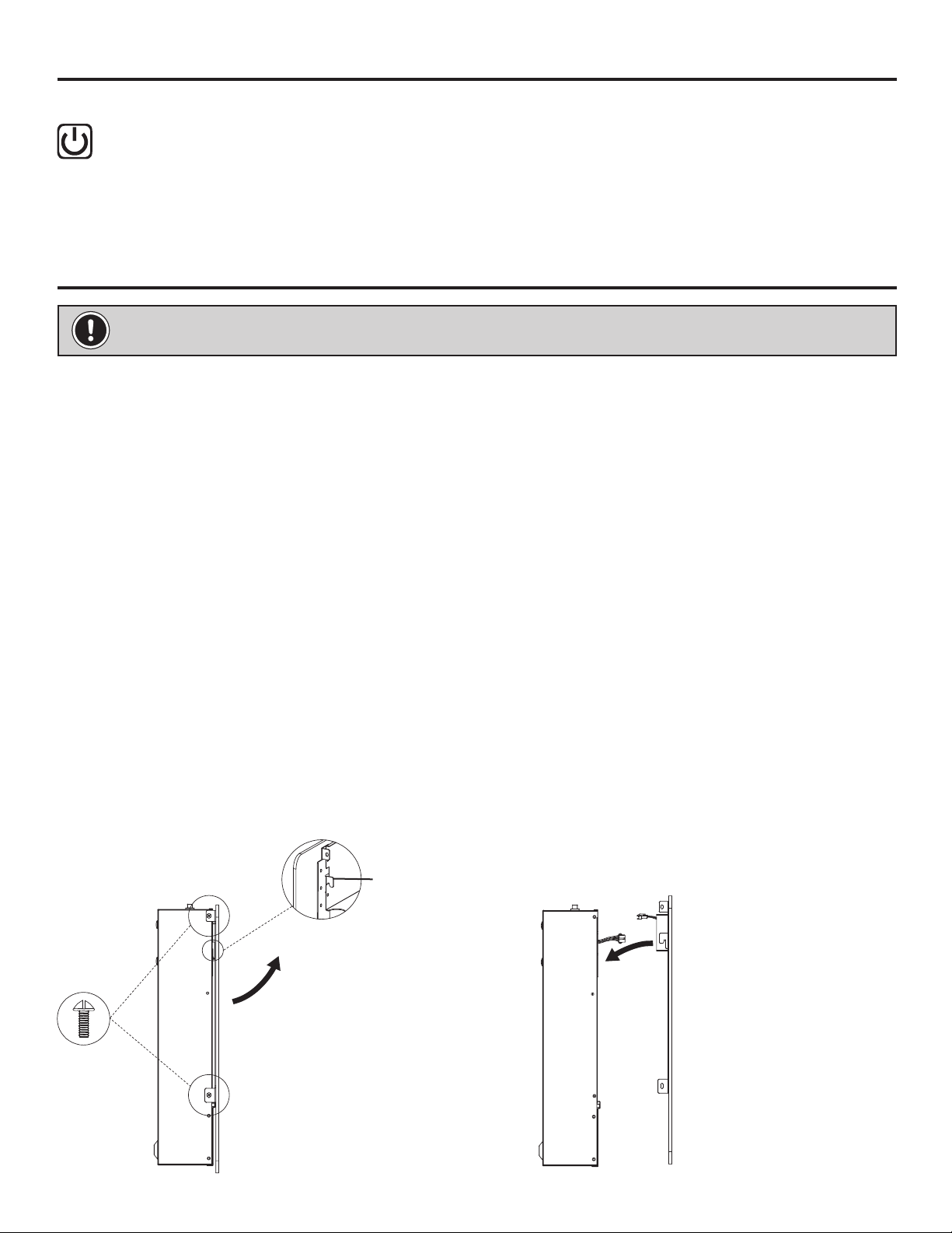
• Cleaning behind the front glass can be done by removing the front glass from the engine assem-
bly. There are two screws on each side of the engine that hold the glass in place. Remove the four
screws that hold the glass and then lift the glass up and away from the engine assembly. While
holding the glass, disconnect the control panel wire harness from the engine assembly. Clean with
a lint free damp cloth. To replace the glass, center the glass over the engine assembly and re-
connect the control panel's wire harness to the engine assembly and lower the glass until it seats.
Install the four screws that you removed into the brackets on each side of the glass. Tighten all the
screws.
Remove the four screws.
Lift the glass up and
away from the rebox.
Disconnect the control
panel wire harness.
Re-connect the control
panel's wire harness.
Lower the glass onto the
rebox.
Install and tighten the
four screws.
Front Glass Removal Front Glass Installation
Hook
15
M
M
N
L
N
L
GND
AC120V/60HZ
S
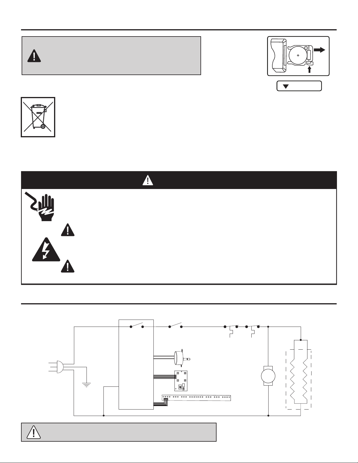
The battery may contain hazardous substances which could endanger the environment
and human health. This symbol marked on the battery and/ or packaging indicates that
used battery shall not be treated as municipal waste. Batteries should be disposed
of at an appropriate collection point for recycling. By ensuring the used batteries are
disposed of correctly, you will help prevent potential negative consequences for the
environment and human health. The recycling of materials will help to conserve natural
resources. For more information about the recycling of used batteries, please contact
your local municipality waste disposal service.
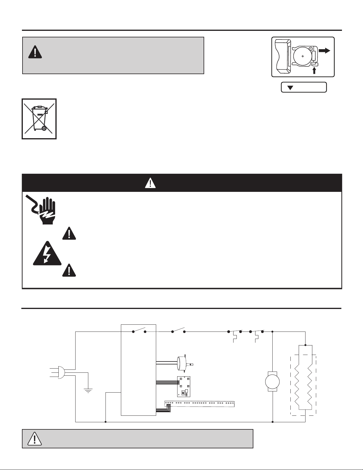
Disconnect power before servicing.
Any electrical re-wiring of this appliance must be done by a qualied electrician.
This wiring must be done in accordance with local codes and/or in Canada with
the current CSA C22.1 Canadian Electrical Code, and for US installations, the
National Electrical Code ANSI/NFPA No. 70.
If repairing or replacing any electrical component or wiring, the original
wire routing, color coding and securing locations must be followed.
DANGER
Circuit
Board
LED
Flame Effect Motor
**Heater Disable
Switch
Self-Hold Thermostat
Heater
Element
Fan
Motor
**Heater Disable Switch on Some Models Only
CARE AND MAINTENANCE (CONTINUED)
CIRCUIT DIAGRAM
Disposal of Used Batteries
CAUTION: Do not mix old and new batteries.
Do not mix alkaline, standard (carbon-zinc), or
rechargeable (ni-cad, ni-mh, etc) batteries.
WARNING: Disconnect power before servicing.
Battery replacement instruction
CR2025
OPEN
PUSH
RELEASE
Battery Replacement
Procedure
Battery Size CR2025
16
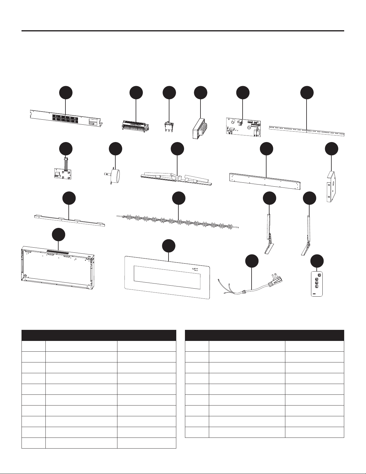
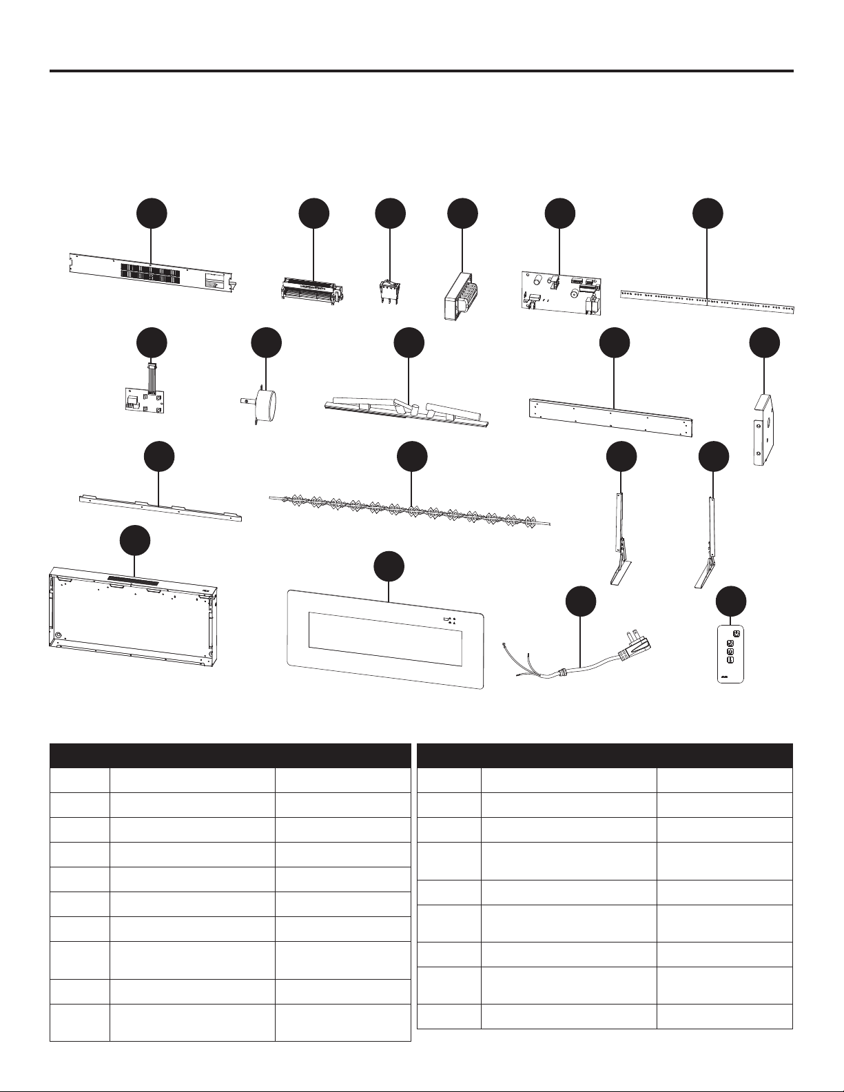
For replacement parts, please call customer service at
1-877-447-4768, 8:00 a.m. – 4:30 p.m. CST, Monday – Friday.
PART DESCRIPTION PART #
1 Middle Panel EF3114210001
2 Fan Heater EF3114210002
3 Switch EF3114210003
4 NTC Plastic Box EF3114210004
5 Main PCB EF3114210005
6 LED PCB EF3114210006
7 Key PCB EF3114210007
8 DC Motor EF3114210008
9 Logset EF3114210009
10 Bottom Cover Panel EF3114210010
PART DESCRIPTION PART #
11 Motor Bracket EF3114210011
12 Mounting Bracket EF3114210012
13 Flame Reector EF3114210013
14 Left Table Top Stand EF3114210014
15 Right Table Top Stand EF3114210015
16 Back Housing Accessory EF3114210016
17 Glass EF3114210017
18 Power Cord & Connector EF3114210018
19 Remote EF33510AS-15
SERVICE PARTS
1
7
12 13 14 15
8 9 10 11
1918
17
16
2 3 4 5 6

17
If you have any questions regarding the product, please call customer service at
1-877-447-4768, 8:00 a.m. – 4:30 p.m. CST, Monday – Friday.
TROUBLESHOOTING
PROBLEM POSSIBLE CAUSE CORRECTIVE ACTION
Fireplace does not
operate.
1. The replace is not
plugged in.
1. Make sure the replace is plugged in
to a standard 120V outlet.
2. A circuit breaker is tripped
or a fuse blown.
2. Check additional appliances on the
circuit; ideally the replace should be
on a dedicated 15 Amp circuit.
3. Defective ON/OFF switch. 3. Call customer service.
4. Loose wiring. 4. Call customer service.
Power light is ON
but the ame effect
is not visible.
1. Incorrect operation. 1. Refer to operating instructions.
2. LED strip is not
functioning.
2. Call customer service.
3. Loose wiring. 3. Call customer service.
Heater is not
operating.
1. Incorrect operation. 1. Refer to operating instructions.
2. Defective heater switch. 2. Call customer service.
3. Defective heater assembly. 3. Call customer service.
4. Loose wiring. 4. Call customer service.
5. Dirty or clogged vents.
5. Unplug the unit. Clear vent area of dust
and debris. Wait ten minutes, plug the unit
in again and turn on the heater.
Display shows "E1". 1. NTC is Defective. 1. Call customer service.
Excessive noise
when the heater is
operating.
1.
Defective fan.
1. Call customer service.
2.
Defective heater assembly.
2. Call customer service.
3.
Dirt/dust on fan.
3. Refer to maintenance section.

18
The manufacturer warrants that your new electric replace is free from manufacturing and material
defects for a period of one year from date of purchase, subject to the following conditions and
limitations.
1. This electric replace must be installed and operated at all times in accordance with the
instructions furnished with the product. Any alteration, willful abuse, accident, or misuse of the
product shall nullify this warranty.
2. This warranty is non-transferrable, and is made to the original owner, provided that the purchase
was made through an authorized supplier of the manufacturer.
3. This warranty is limited to the repair or replacement of part(s) found to be defective in material or
workmanship, provided that such part(s) have been subjected to normal conditions of use and
service, after said defect is conrmed by the manufacturer’s inspection.
4. The manufacturer may, at its discretion, fully discharge all obligations with respect to this
warranty by refunding the wholesale price of the defective part(s).
5. Any installation, labor, construction, transportation, or other related costs/expenses arising from
defective part(s), repair, replacement, or otherwise of same, will not be covered by this warranty,
nor shall the manufacturer assume responsibility for same. Further, the manufacturer will not be
responsible for any incidental, indirect, or consequential damages, except as provided by law.
6. All other warranties - expressed or implied - with respect to the product, its components and
accessories, or any obligations/liabilities on the part of the manufacturer are hereby expressly
excluded.
7. The manufacturer neither assumes, nor authorizes any third party to assume, on its behalf,
any other liabilities with respect to the sale of this product.
8. The warranties as outlined within this document do not apply to non-manufacturer accessories
used in conjunction with the installation of this product.
This warranty is void if:
a) The replace has been operated in atmospheres contaminated by chlorine, uorine or
other damaging chemicals.
b) The replace is subjected to prolonged periods of dampness or condensation.
c) Any alteration, willful abuse, accident, or misuse of the product.
IF WARRANTY SERVICE IS NEEDED . . .
1) Contact customer service at 1-877-447-4768, 8:00 a.m. – 4:30 pm CST, Monday – Friday.
Make sure you have your warranty, your sales receipt, and the model/serial number
of your product.
2) DO NOT ATTEMPT TO DO ANY SERVICE WORK YOURSELF.
WARRANTY
GHP Group, Inc.
6440 W. Howard St. • Niles, IL. • 60714-3302
271 Massey Road, Guelph, Ontario, N1K 1B2
Printed in China
19
255895
English p. 1
CHIMENEA ELECTRICA
MODELO # 311-42-10
INSTALADOR: Deje este manual con el electrodoméstico.
CONSUMIDOR: Conserve este manual para referencia futura.
¡ADVERTENCIA!
SI NO SE SIGUE CON PRECISIÓN LA INFORMACIÓN DE ESTE MANUAL, SE
PUEDE PRODUCIR UNA DESCARGA ELÉCTRICA O UN INCENDIO QUE
PRODUZCA DAÑOS A LA PROPIEDAD, LESIONES PERSONALES O MUERTE.
INSTRUCCIONES IMPORTANTES
LEA ESTE MANUAL ANTES DE INSTALAR Y USAR EL ELECTRODOMÉSTICO
¿Preguntas, problemas, piezas faltantes? Antes de volver a la tienda, comuníquese
con nuestro departamento de Servicio al Cliente llamando al 877-447-4768, de
8:00 a.m. a 4:30 p.m., HEC, de lunes a viernes.
ADJUNTE SU RECIBO AQUÍ
Número de serie _____________________________ Fecha de compra _____________________________
20
IMPORTANTE: lea con atención todas las instrucciones y advertencias antes de
comenzar la instalación. Si no se siguen las instrucciones, se puede provocar una
descarga eléctrica, lesiones a personas, riesgo de incendio, lo que anulará la garantía.
Lea estas instrucciones de instalación y funcionamiento antes de utilizar el
electrodoméstico.
ÍNDICE
Información de seguridad ................................................................................................................3
Contenido del paquete .....................................................................................................................5
Dimensiones de la chimenea ...........................................................................................................6
Preparación ......................................................................................................................................7
Conexión eléctrica ............................................................................................................................4
Instrucciones de puesta a tierra .......................................................................................................4
Control remoto .................................................................................................................................7
Instrucciones de ensamblaje ............................................................................................................7
Preinstalación ................................................................................................................................... 7
Instalación: Fijación a pared .............................................................................................................7
Instalación: Mueble ..........................................................................................................................7
Instrucciones de operación ..............................................................................................................8
Cuidado y mantenimiento ................................................................................................................9
Diagrama del cableado eléctrico ....................................................................................................10
Listas de piezas de repuesto .........................................................................................................13
Solución de problemas ..................................................................................................................11
Garantía ..........................................................................................................................................12
EL DAÑO DEL PRODUCTO PUEDE OCURRIR.
Nunca trate de desarmar o alterar este producto sin seguir las instrucciones de este manual.
PRECAUCIÓN

21
1. Lea todas las instrucciones antes de usar este calefactor.
2. Siempre desenchufe este electrodoméstico cuando no se encuentre en uso.
3. Advierta a los niños de que no jueguen con este calefactor.
4. No haga funcionar el calefactor con un cable o enchufe dañado luego de una falla, de que se haya
caído o se haya dañado de algún modo. Lleve el calefactor a un servicio técnico autorizado para
que lo revisen, le realicen un ajuste eléctrico o mecánico, o lo reparen.
5. Sólo el servicio técnico autorizado y capacitado deberá reparar este electrodoméstico.
6. Este electrodoméstico no deberá ser modicado bajo ninguna razón. Las partes que se quiten para
su mantenimiento sólo podrán ser reemplazadas con partes “OEM” (que provenga de un fabricante
de equipamiento original).
7. No se utilice al aire libre.
8. Este electrodoméstico no está diseñado para su uso en baños, lavaderos u otros lugares similares.
Nunca coloque este electrodo méstico en donde pueda caer a una bañera u otro recipiente con
agua.
9. No pase el cable de alimentación por debajo de alfombrado. No cubra el cable de alimentación con
artículos tales como tapetes o alfombras de pasillo, entre otros. Mantenga el cable de alimentación
lejos de áreas de circulación para asegurarse de que no estorbe.
10. Para desconectar el calefactor, ponga los controles en OFF y luego quite el enchufe de la toma de
corriente.
11. Conecte sólo a tomas de corriente correctamente conectadas a tierra.
12. Este electrodoméstico, una vez instalado, debe de estar conectado a tierra conforme a los códigos
locales, bajo los códigos actuales CSA C22.1 de Electricidad Canadiense, o, para instalaciones en
E.U.A. siga los códigos locales y el Código Eléctrico Nacional, ANSI/NFPA no. 70.
13. Hay un termostato limitador dentro del calefactor. Cuando la temperatura interior se sobrecalienta
o en el caso de un calentamiento anormal, el dispositivo protector del termostato cortará la
alimentación para evitar el daño al calefactor y el riesgo de incendio.
14. Este electrodoméstico contiene partes calientes y arqueadas o chispeantes en su interior. No se
utilice en áreas en donde se use o almacene gasolina, pintura o líquidos inamables. Este electrodo
méstico no debe ser utilizado como tendedero para la ropa, ni tam poco debe de haber medias de
Navidad o decoraciones colgadas sobre o cerca de él.
15. Utilice este aparato sólo tal y como se describe en este manual. Cualquier otro uso no recomendado
por el fabricante podría resultar en un incendio, una descarga eléctrica o daños personales.
16. El uso de una extensión eléctrica no es recomendada por el riesgo de incendio. Si se utiliza una
extensión debe ser mínimo del No.14 AW nominal no inferior a 1875 W, y el cable de extensión debe
ser un cable de tres clavijas con conexión a tierra el enchufe y el conector de cable. El cable de
extensión no debe ser superior a 6 metros de longitud.
17. No utilice este aparato con un temporizador programable o cualquier otro dispositivo que encienda
y apague el aparato de forma automática. Para evitar el peligro debido al reajuste accidental del
protector térmico, este aparato no debe ser suministrado mediante un interruptor externo como un
temporizador, ni conectado a un circuito que sea regularmente apagado y encendido por un servicio
público.
18. Este producto contiene una batería de botón. Si se ingiere, puede causar lesiones graves o la
muerte en tan sólo 2 horas. Busque atención médica de inmediato.
Lea y comprenda completamente este manual antes de intentar ensamblar, usar o instalar el producto.
INFORMACIÓN DE SEGURIDAD GUARDE ESTAS INSTRUCCIONES
22
INFORMACIÓN DE SEGURIDAD (CONTINUACIÓN)
PRECAUCIÓN: Utilizar sólo con el soporte proporcionado o montado en la pared. No
instale el calentador a menos de 60 cm / 23,6 pulgadas del piso.
PRECAUCIÓN: No introduzca ni permita que objetos extraños entren en las aberturas de
ventilación o de escape, ya que esto puede causar una descarga eléctrica o un incendio,
o daños a la chimenea.
PRECAUCIÓN: Al usar electrodomésticos, siempre se deben de seguir precauciones
básicas para reducir el riesgo de incendio, descargas eléctricas y lesiones a personas.
IMPORTANTE: GUARDE ESTAS INSTRUCCIONES.
ADVERTENCIA: Este calentador está caliente cuando se encuentra en uso. Para evitar
quemaduras, no permita que la piel al descubierto toque las supercies calientes. Si se
proporcionan, utilice manijas para mover este electrodoméstico. Mantenga materiales
combustibles, tales como muebles, almohadas, sobrecamas, papeles, ropa y cortinas al
menos a 0.9 metros de distancia de la parte frontal, los laterales y la parte trasera.
ADVERTENCIA: Este producto puede exponerlo a usted a agentes químicos incluyendo
ftalato de diisononilo (DINP), reconocido por el estado de California como causante de
cáncer, así como ftalatos de diisodecilo (DIDP), reconocidos por el estado de California
como causantes de problemas de crecimiento.
Para obtener más información, visite www.p65Warnings.ca.gov
PRECAUCIÓN: Tenga mucho cuidado cuando cualquier chimenea esté siendo
utilizada por o cerca de niños o minusválidos, y cuando el calentador se encuentre
en funcionamiento sin ser supervisado.
PRECAUCIÓN: Para evitar un posible incendio, no bloquee las entradas de aire de la
chimenea o del escape de ninguna manera. No opere la chimenea sobre supercies
blandas, como lo es una cama, en donde las aberturas puedan ser bloqueadas.
23
PARTE DESCRIPCIÓN CANTIDAD
A Calefactor 1
B Control remoto 1
C Soporte de montaje 1
D Soporte de pie derecho 1
E Parte inferior del pie derecho 1
F Soporte de pie izquierdo 1
G Parte inferior del pie izquierdo 1
CONTENIDO DEL PAQUETE
A
DG
F E
C
B
24
REF. 311-42-10
A 10.5 pulg.
B 21 pulg.con soporte
C 17.3 pulg. sin soporte
D 42 pulg.
ESPECIFICACIONES TÉCNICAS
Voltaje 120V AC
Frecuencia 60HZ
Amperaje 11.7A
Potencia de servicio del calentador 1400W
DIMENSIONES DE LA CHIMENEA
ESPACIO LIBRE A COMBUSTIBLES
Lados 4 pulg. (101.6 mm)
Suelo 0 pulg. (0 mm)
Cima 36 pulg. (914 mm)
Delantero 36 pulg. (914 mm)
Trasero 0 pulg. (0 mm)
B
C
A
D
ADVERTENCIA: Mantenga
materiales combustibles, tales
como muebles, almohadas,
sobrecamas, papeles, ropa y
cortinas al menos a 0.9 metros
de distancia de la parte frontal,
los laterales y la parte trasera.
25
Plan de Instalación
Antes de comenzar con el ensamblado, localice las instrucciones y las partes. Compare todas las
partes con la herramienta incluida y con las listas del contenido del empaque. Asegúrese de contar
con todas las partes e identicarlas. Una mano amiga siempre es bienvenida. Si es posible, ensam-
ble su calefactor con un asistente adulto. Algunas partes son pesadas y tendrán que ser sostenidas
por un ayudante. El tiempo de ensamblado tomará aproximadamente de 5 minutos a 20 minutos.
Antes del ensamblado, utilice tijeras para desenvolver las partes del empaque. No utilice una navaja
o cuchillo exacto, ya que puede cortar las partes del calefactor dentro de la caja y dañar el acabado.
Busque la bolsa de herramientas situada en el interior del empaque, que se encuentra pegada a la
parte superior de la caja. No deseche ninguna pieza. Utilice un desarmador apropiado para insertar
y apretar todos los tornillos.
Conexión eléctrica
Instrucciones de puesta a tierra
Para el funcionamiento correcto de este aparato se necesita un circuito de 15 A, 120 V, 60 Hz con un
tomacorriente debidamente conectado a tierra. Preferentemente, el inserto para el calefactor deberá
contar con un circuito exclusivo, ya que otros aparatos en el mismo circuito pueden disparar o que-
mar al fusible cuando está funcionando el calefactor. La unidad viene de fábrica con un cable de tres
conductores de 1,8 metros y que sale por detrás del inserto del calefactor. Planee la instalación para
evitar el uso de un cable de extensión. Sin embargo, si usted tiene que usar un cable de extensión,
el cable deberá ser de calibre 14 AWG cuando menos y para una potencia nominal de 1,875 W El
cable de extensión no deberá tener más de 6 metros de largo.
Este calefactor es para uso con 120 voltios. El cable
tiene un enchufe con se muestra en (A) en la Figura 1.
Un adaptador como se muestra en (C) está disponible
para conectar enchufes de tres cuchillas con conexión
a tierra. La orejeta verde de conexión a tierra que se
extiende del adaptador, debe ser conectada a una tierra
permanente como una caja de salida aterrizada adecua-
damente. El adaptador no debe ser usado si está dis-
ponible un receptáculo aterrizado de tres ranuras.
PREPARACIÓN
PRECAUCIÓN: ¡Esta caja contiene un panel de vidrio! Tenga extremo cuidado siempre que
esté manejando cristal. El no hacerlo podría resultar en daños personales o materiales.
ADVERTENCIA: El cableado de la toma de corriente debe cumplir con los códigos locales
de construcción y demás normativas aplicables para reducir el riesgo de incendio, descar-
ga eléctrica y lesiones a personas.
ADVERTENCIA: No utilice este calefactor si cualquier parte del mismo ha estado bajo el
agua. Llame inmediatamente a un técnico calicado para que inspeccione el calefactor y
reemplace cualquier parte del sistema eléctrico que haya estado bajo el agua.
Chuchilla de tierra
Cubierta de caja de salida aterrizada
Adaptador
Punto para conexión a tierra
Tornillo metálico
Cubierta de caja de salida aterrizada
A
B
C
NOTA: Los adaptadores NO son para uso
en Canada.
1
26
PREINSTALACIÓN
Este dispositive cumple con las reglas de la FCC parte 15 y la and Canadian ICES-003. La operacion
esta sujeta a las siguientes dos condiciones:
(1) Este dispositivio no puede causar interferencias perjudiciales, y (2) este dispositive debe acep-
tar cualquier interferencia recibida, incluyendo interferencias que pueda causar funcionamiento no
deseado. No existe garantía de que no ocurra interferencia en una instalación en particular. Si este
equipo efectivemente causa interferencia dañina a la recepción de radio o televisión, lo cual puede
determinarse apagando y encendiendo el equipo, se recomienda al usuario que trate de corregir la
interferencia realizando uno o varios de los siguientes pasos:
• Cambie de dirección o de lugar la antena receptora.
• Aumente la separación entre el equipo y el receptor.
• Conecto el equipo en un tomacorriente en un circuito diferente de done esté conectado el
receptor.
• Consulte al concesionario o a un técnico de radio/TV con experiencia para que le ayude.
Este control remoto requiere 1 batería plana de litio (tamaño CR2025), la cual viene incluida.
CONTROL REMOTO
PRECAUCIÓN: Cambios o modicaciones a esta unidad que no esten expresamente
aprobado porla parte responsable por conformidad puede anular el autorizacion del
usario para operar el equipo.
ADVERTENCIA: NO mezcle baterías viejas con nuevas.
NO use baterías recargables de óxido de plata con la unidad del control remoto.
NO mezcle baterías alcalinas, estándar (Carbón-Cinc) o recargables (Níquel-Cadmio).
NO deseche las baterías en el fuego. La eliminación inadecuada puede hacer que las baterías
goteen o exploten.
Herramientas requeridas (no incluidos)
Gafas de
seguridad
Desarmador
Phillips
Taladro
Herramientas incluídas
NOTA: Las herramientas son mostradas en
su tamaño real.
AA BB CC DD
Parte Descripción Cant.
AA Tornillo pequeño 4
BB Tornillo grande 4
CC Anclaje de pared 4
DD Tornillo largo 6
27
C
CC
BB
C
1. Lija una pared sólida. Posicione el soporte de
montaje (C) donde vaya a instalar el calefactor
(A) en la pared, y asegúrese de que el soporte de
montaje (C) esté a nivel.
Utilice un bolígrafo para marcar los 2 agujeros
de montaje en la pared, en el lugar deseado,
utilizando como modelo el soporte de montaje (C).
2. Inserte los 4 anclajes de auto-taladrado (CC) en
el lugar marcado en la pared. Si está instalando el
soporte de montaje (C) a un montante de la pared,
no hay necesidad de taladrar los agujeros en la
madera ni necesita usted los anclajes de pared
(CC). Se recomienda instalar el soporte de montaje
al menos a un montante.
3. Fije el soporte de montaje (C) a la pared con 4
tornillos grandes (BB).
1
2
3
INSTALACIÓN: FIJACIÓN A PARED

28
4. Colocación de la cámara de combustión eléctrica
(A) al soporte de montaje (C).
1. Fije el soporte izquierdo (G) a las patas de la base
izquierda (F) utilizando 3 tornillos largos (DD).
2. Fije el soporte derecho (D) a las patas de la base
derecha (E) utilizando 3 tornillos largos (DD).
4
1
2
INSTALACIÓN: FIJACIÓN A PARED (CONTINUACIÓN)
INSTALACIÓN: MUEBLE
C
A
Pared
DD
G
D D
G
F
E
E
F
DD
29
Disable Heater
Calefacción deshabilitada
Enable Heater
Calefacción habilitada
3. Utilice un destornillador para asegurar la cámara
de combustión del montaje (A) a los soportes
izquierdo y derecho de la mesa con 4 tornillos
pequeños (AA).
3
INSTALACIÓN: MUEBLE (CONTINUACIÓN)
Lea todas las instrucciones antes de usar este calefactor
Figura 2
Verique que la rejilla de salida del calefactor no esté cubierta u obstruida de ninguna manera, y
asegúrese de que la alimentación a la unidad esté encendida.
INSTRUCCIONES DE OPERACIÓN
NOTA: Esta unidad está equipada con un interruptor en el panel superior que desactiva
el calefactor (vea la gura 2). Para activar el calefactor, por favor asegúrese de que el
interruptor esté en el modo “encendido”. El calefactor funcionará utilizando el control
remoto o el panel de control en la parte frontal de la unidad.
AA
30
INSTRUCCIONES DE OPERACIÓN (CONTINUACIÓN)
Uso del manual y controles remotos
Cómo utilizar el botón de encendido
Cómo utilizar el botón de control de llama
El panel de control se encuentra en la placa superior derecha del calefactor (A). Este panel contiene
los botones para la correcta operación. Los botones en el panel de control a uno de los lados del
calefactor (A) y el control remoto (B) funcionan de la misma manera. El control remoto tiene un
alcance efectivo de hasta 3.9 m / 13 pi.
• El botón de encendido principal (1) está situado en el panel
de control al frente al calentador.
• Pulsar el botón de encendido (1) una vez enciende el equipo.
• Pulsar el botón de encendido (1) de nuevo apaga el equipo.
• Si parece que ninguno de los otros botones funcionan,
asegúrese de que el botón de encendido principal (1) esté
encendido.
• Pulse el botón de control de
llama (2) para encender la
capa de brasas y el efecto
llama.
• Pulsar el botón de control de
llama (2) una vez enciende las
llamas e ilumina la capa de
brasas.
• Pulsar el botón de control de
llama (2) de nuevo recorrerá
los diferentes colores de la
capa de brasas. La modalidad
de rotación de color recorrerá
las modalidades de color de
manera continua. Reé ase a
la tabla para más información.
Verique que la rejilla de salida del calentador no esté cubierta u obstruida de ninguna manera, y
asegúrese de que la unidad esté encendida. Se puede acceder a la chimenea de dos formas:
mediante el panel de control del panel táctil o mediante el mando a distancia multifunción.
Presione el botón apropiado para operar su chimenea:
1. Botón de encendido
2. Botón de control de la llama
3. Botón de control del termostato
4. Botón de control del temporizador
5. Panel de la pantalla digital
JY-3B
JY-3B
1
2
4
1
3
5
2
4
3
La lengüeta de plástico dentro del
compartimiento de la batería debe quitarse
antes de que funcione el control remoto.
(lengüeta de plástico)
Pulsación
del botón
Valor de
visualización
Efecto de
la llama
1 1 Naranja
2 2 Verde
3 3 Azul
4 4 Naranja y Verde
5 5 Naranja y Azul
6 6 Naranja y Verde y Azul
7 7 Rotación de colores
31
INSTRUCCIONES DE OPERACIÓN (CONTINUACIÓN)
Cómo utilizar el botón de control
del termóstato
Cómo utilizar el botón de control del temporizador
Este botón controla el encen-
dido / apagado del calentador.
Cuando la unidad de tempera-
tura se establece como "F" o
"C", el alcance de temperatura
es como se muestra en la tabla.
Para mostrar la conguración
de la temperatura tanto en
grados Fahrenheit como en
Celsius, pulse una vez el botón
de calefacción (3) del panel de
control, luego pulse y mantenga
pulsado el botón de encendido
(1) del panel de control durante
5 segundos. La pantalla cambi-
ará entre Fahrenheit y Celsius.
Pulsando el botón de control del temporizador (4)
congurará el temporizador. Este intervalo de tiempo
se muestra en la pantalla (5) en el panel de control
en el frente de la cámara de combustión eléctrica.
Los diferentes intervalos se enumeran en la tabla.
NOTA: Si este producto se somete a temper-
aturas excepcionalmente altas, puede dejar
de calentar automáticamente. En este caso,
el producto debe desconectarse o aislarse de
la fuente de alimentación principal durante 30
segundos antes de volver a encenderlo.
Pulsación
del botón
Celsius
Temperature
1 17 ˚C
2 18 ˚C
3 19 ˚C
4 20 ˚C
5 21 ˚C
6 22 ˚C
7 23 ˚C
8 24 ˚C
9 25 ˚C
10 26 ˚C
11 27 ˚C
12 28 ˚C
13 29 ˚C
14 30 ˚C
15 ON
Pulsación
del botón
Intervalo del
temporizado
Valor en
pantalla
1 1 Hora 1H
2 2 Horas 2H
3 3 Horas 3H
4 4 Horas 4H
5 5 Horas 5H
6 6 Horas 6H
7 7 Horas 7H
8 8 Horas 8H
Pulsación
del botón
Fahrenheit
Temperature
1 62 ˚F
2 63 ˚F
3 64 ˚F
4 65 ˚F
5 66 ˚F
6 67 ˚F
7 68 ˚F
8 69 ˚F
9 70 ˚F
10 71 ˚F
11 72 ˚F
12 73 ˚F
13 74 ˚F
14 75 ˚F
15 76 ˚F
16 77 ˚F
17 78 ˚F
18 79 ˚F
19 80 ˚F
20 81 ˚F
21 82 ˚F
22 83 ˚F
23 84 ˚F
24 85 ˚F
25 86 ˚F
26 ON
32
• Limpie la supercie exterior del calefactor de vez en cuando con un paño suave y húmedo (que no
esté muy mojado), y seque la supercie antes de operar la unidad.
• No sumerja el calefactor en agua.
• No utilice productos de limpieza químicos como detergentes o abrasivos.
• No permita que el interior se moje, ya que esto podría crear un peligro.
• Si se acumula un poco de polvo en el calefactor, puede limpiarse con un paño seco y suave.
• Para guardar el calefactor, póngalo de nuevo en su embalaje original y guárdelo en un lugar limpio
y seco.
• El ventilador y el motor de la llama vienen pre-lubricados para un uso duradero, sin necesidad de
más lubricación o mantenimiento.
• Es posible que se acumulen partículas de polvo encima y dentro del calefactor, así que se reco-
mienda la limpieza o aspiración de éste.
• Siempre apague el calefactor y desconecte el cable eléctrico del tomacorriente antes de limpiarlo.
• La limpieza detrás del cristal frontal puede realizarse removiendo el cristal frontal del ensamblaje
del motor. Hay dos tornillos de cada lado del motor que mantienen al cristal en su lugar. Quite los
cuatro tornillos que sujetan al cristal y luego levante el cristal hacia arriba retirándolo del ensamb-
laje del motor. Mientras sujeta el cristal, desconecte el arnés de los cables del panel de control del
ensamblaje del motor. Límpielo con un paño húmedo sin pelusas. Para volver a colocar el cristal,
centre el cristal sobre el ensamblaje del motor y reconecte el arnés de los cables del panel de con-
trol al ensamblaje del motor y bájelo hasta que se asiente. Coloque los cuatro tornillos que había
quitado en los soportes de cada lado del cristal. Apriete todos los tornillos.
Para apagar el modo de calefacción, pulse y mantenga pulsado el botón de llama durante 10
segundos para entrar en el modo de bloqueo de calefacción. Las luces de llama parpadearán
6 veces para indicar que la función de calefacción se ha apagado y bloqueado. Para encender
el modo de calefacción, pulse y mantenga pulsado el botón de calefacción durante 10 segun-
dos. Las luces de la llama parpadearán 6 veces y la función de calefacción se restablecerá.
Cuando el botón de calefacción se pulse en modo bloqueo, el lecho de brasas parpadeará 6
veces hasta que el modo calefacción se encienda.
Gancho
INSTRUCCIONES DE OPERACIÓN (CONTINUACIÓN)
CUIDADO Y MANTENIMIENTO
Función de bloqueo
Desinstalación del
cristal frontal
Instalación del cristal
frontal
IMPORTANTE: Desenchufe siempre el cable de alimentación antes de limpiar la unidad.
Deje que la unidad se enfríe antes de limpiarla.
Quite los cuatro tornillos .
Levante el cristal hacia arriba
retirándolo del ensamblaje
del motor.
desconecte el arnés de los
cables del panel de control.
Reconecte el arnés de
los cables del panel de
control .
Bájelo hasta que se
asiente.
Coloque y apriete todos
los tornillos.
33
M
M
N
L
N
L
GND
AC120V/60HZ
S
La pila puede contener sustancias peligrosas que podrían poner en peligro el medio
ambiente y la salud humana. Este símbolo impreso en la pila y/o envoltorio indica que la
pila usada no debe tratarse como residuo municipal. Las pilas deben desecharse en un
centro de recolección adecuado para su reciclaje. Al asegurarse de desechar correcta-
mente las pilas usadas, usted estará ayudando a prevenir potenciales consecuencias
negativas para el medio ambiente y la salud humana. El reciclaje de materiales ayudará
a conservar los recursos naturales. Para obtener mayor información sobre el reciclado
de pilas usadas, por favor contacte al servicio de administración de desechos de su
municipalidad.
Desconecte la energía antes de dar servicio.
Cualquier renovación de cableado de este dispositivo debe ser hecho por un
electricista calicado. Este cableado debe ser hecho de acuerdo con códigos
locales y/o en Canadá con el Código Eléctrico Canadiense actual CSA C22.1 y
para instalaciones en los EE. UU., el Código Eléctrico Nacional ANSI/NFPA NO
70.
Si se repara o reemplaza cualquier componente eléctrico o el cableado,
el enrutamiento original de cables, la codificación de color y ubicaciones
seguras deben seguirse.
PELIGRO
Placa de
circuitos
LED
Motor de efectos
de llamas
**Interruptor de
desactivación del
calentador
Corte operaciones
térmico
Elemento
calentador
Calentador de
ventilador
**Interruptor de desactivación del calentador solo en algunos modelos
CUIDADO Y MANTENIMIENTO (CONTINUACIÓN)
DIAGRAMA DE CIRCUITO
Cómo desechar las pilas usadas
PRECAUCIÓN: No mezcle pilas nuevas y
usadas. No mezcle pilas alcalinas, estándar
(carbono-zinc), o baterías recargables (NiCd y
NiMH, etc).
ADVERTENCIA: Desconecte la energía antes de dar servicio.
Battery replacement instruction
CR2025
OPEN
PUSH
RELEASE
Reemplazo de la pila
Pila de litio de 3 V
tipo moneda celular
CR2025
34
Para piezas de repuesto, llame al Servicio al Cliente al
1-877-447-4768, de 8:00 a.m. a 4:30 p.m., HEC, de lunes a viernes.
PIEZA DESCRIPCIÓN PIEZA NO.
1 Panel medio EF3114210001
2 Calentador EF3114210002
3 Cambiar EF3114210003
4 Caja de plástico NTC EF3114210004
5 PCB principal EF3114210005
6 PCB LED EF3114210006
7 PCB clave EF3114210007
8
Motor de corriente
continua
EF3114210008
9 Logset EF3114210009
10
Panel de cubierta
inferior
EF3114210010
PIEZA DESCRIPCIÓN PIEZA NO.
11 Soporte del motor EF3114210011
12 Soporte de montaje EF3114210012
13 Reector de llama EF3114210013
14
Soporte de mesa
izquierdo
EF3114210014
15 Soporte de mesa derecho EF3114210015
16
Accesorio de carcasa
trasera
EF3114210016
17 Vidrio EF3114210017
18
Cable de alimentación y
conector
EF3114210018
19 Remoto EF33510AS-15
PARTES DE SERVICIO
1
7
12 13 14 15
8 9 10 11
1918
17
16
2 3 4 5 6

35
Si tiene preguntas relacionadas con el producto, llame al Servicio al Cliente al
1-877-447-4768, de 8:00 a.m. a 4:30 p.m., HEC, de lunes a viernes.
Solución de problemas
PROBLEMA CAUSA POSIBLE ACCIÓN CORRECTIVA
La chimenea no
funciona.
1. La chimenea no está
enchufada.
1. Asegúrese de que la chimenea esté
enchufada a un tomacorriente estándar de
120 V.
2. Un interruptor de circuito
se desconectó o se fundió
un fusible.
2. Compruebe si hay otros electrodomésticos
conectados al circuito; idealmente, la
chimenea debe estar conectada a un
circuito dedicado de 15 amperios.
3. Interruptor de
ENCENDIDO/APAGADO
defectuoso.
3. Llame a Servicio al Cliente.
4. Cableado suelto. 4. Llame a Servicio al Cliente.
La luz de encendido
está encendida pero
la llama posterior
no brilla o no está
visible.
1. Funcionamiento
incorrecto.
1. Consulte las instrucciones de operación.
2. La tira de LED no está
funcionando.
2. Llame a Servicio al Cliente.
3. Cableado suelto. 3. Llame a Servicio al Cliente.
El calentador no
funciona.
1. Funcionamiento
incorrecto.
1. Consulte las instrucciones de operación.
2. Interruptor del calentador
defectuoso.
2. Llame a Servicio al Cliente.
3. Ensamble del calentador
defectuoso.
3. Llame a Servicio al Cliente.
4. Cableado suelto. 4. Llame a Servicio al Cliente.
5. Rejillas de ventilación
sucio u obstruido.
5. Desenchufe la unidad. Limpie el polvo
y los desechos del área de las rejillas
de ventilación. Espere diez minutos,
vuelva a enchufar la unidad y encienda el
calentador.
La pantalla muestra
"E1".
1. NTC es defectuoso. 1. Llame a Servicio al Cliente.
Ruido excesivo
cuando el calentador
está funcionando.
1.
Ventilador defectuoso.
1. Llame a Servicio al Cliente.
2.
Asamblaje de la estufa
defectuoso.
2. Llame a Servicio al Cliente.
3.
Suciedad/polvo en el
ventilador.
3. Reérase a la sección de mantenimiento.

36
El fabricante garantiza que su nueva chimenea eléctrica no presentará defectos de fabricación
ni materiales durante un período de un año a partir de la fecha de compra, siempre y cuando se
cumplan las siguientes condiciones y limitaciones.
1. Esta chimenea eléctrica se debe instalar y operar en todo momento de acuerdo con las
instrucciones de instalación y operación proporcionadas con el producto. Cualquier alteración,
abuso deliberado, accidente o uso inadecuado del producto anulará esta garantía.
2. Esta garantía no es transferible y sólo está disponible para el propietario original, siempre y
cuando la compra se haya realizado a través de un proveedor autorizado de la Compañía.
3. Esta garantía se limita a la reparación o reemplazo de piezas que se consideren defectuosas en
material o mano de obra, siempre y cuando dicha pieza haya estado sometida a condiciones
normales de uso y servicio, después de que una inspección por parte de la Compañía conrme dicho
defecto.
4. La Compañía podrá, bajo su criterio, eximirse de toda obligación respecto de esta garantía
reembolsando el precio al por mayor de la pieza defectuosa.
5. Esta garantía no cubrirá ningún costo de instalación, mano de obra, construcción, transporte o de
otro tipo que surja de la pieza defectuosa, su reparación, reemplazo u otra situación, y la Compañía
no asumirá ninguna responsabilidad por las mismas. La Compañía tampoco será responsable por
ningún daño accidental, indirecto o resultante, salvo que la ley estipule lo contrario.
6. Mediante el presente, se excluye expresamente cualquier otra garantía, expresa o implícita,
respecto del producto, sus componentes y accesorios, o cualquier otra obligación o
responsabilidad de parte de la Compañía.
7. La Compañía no asume, ni autoriza a ningún tercero a asumir en su nombre, ninguna otra
responsabilidad respecto de la venta de este producto.
8. Las garantías descritas en este documento no se aplican a accesorios que no sean de el
fabricante y que se usen junto con la instalación de este producto.
Esta garantía es nula si:
a) La chimenea ha funcionado en atmósferas contaminadas con cloro, úor u otras sustancias
químicas dañinas.
b) La chimenea está sometida a períodos prolongados de humedad o condensación.
c) Se produce cualquier alteración, abuso deliberado, accidente o uso inadecuado del producto.
SI SE NECESITA SERVICIO DE GARANTÍA. . .
1) Póngase en contacto el fabricante con el Servicio al Cliente de al 1-877-447-4768,
de 8:00 a.m. a 4:30 p.m., HEC, de lunes a viernes. Asegúrese de tener su garantía, su recibo
de venta y el modelo o número de serie de su producto el fabricante.
2) NO INTENTE REALIZAR NINGÚN TRABAJO DE REPARACIÓN USTED MISMO.
GARANTÍA
GHP Group, Inc.
6440 W. Howard St. • Niles, IL. • 60714-3302
271 Massey Road, Guelph, Ontario, N1K 1B2
Impreso en China