Mr. Heater F272700 40,000 BTU Propane Non-Vented Infrared Heater

Operating Instructions and Owner’s Manual - Page 4

For F272700. Also, The document are for others Mr. Heater models: MH40NG, MH40LP

PDF File Manual, 24 pages, Read Online | Download pdf file

F272700 photo
Loading ...
Loading ...
Loading ...
E4


3. SUSPENSION




4. GAS SUPPLY













5. PIPING REQUIREMENTS










USE MODERATE AMOUNT OF PIPE DOPE

Figure 1. Pipe Compound Application













NOTE:


 
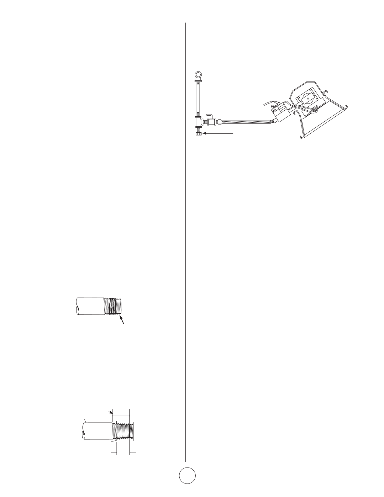
Figure 3. Typical Piping Installation
6. GAS PRESSURE












7. ELECTRICAL


8. THERMOSTAT & LOCATION



DO NOT MOUNT directly to cold-side wall, in
direct drafts, or directly beneath the infra-red heater.












Figure 2.
Gas valve
connection
requirements

Loading ...
Loading ...
Loading ...