
Loading ...
Loading ...
Loading ...
W415-2835 / B / 04.05.21
EN
26
venting requirements
A. Remove the safety barrier and glass door (see "safety barrier & door removal/installation" section).
B. Remove the contents from the fi rebox and set aside.
You will need the exhaust and air inlet collar.
C. To ease assembly, remove the 4 hex head screws,
securing the defl ector from inside the top front of the
fi rebox (Fig. 1).
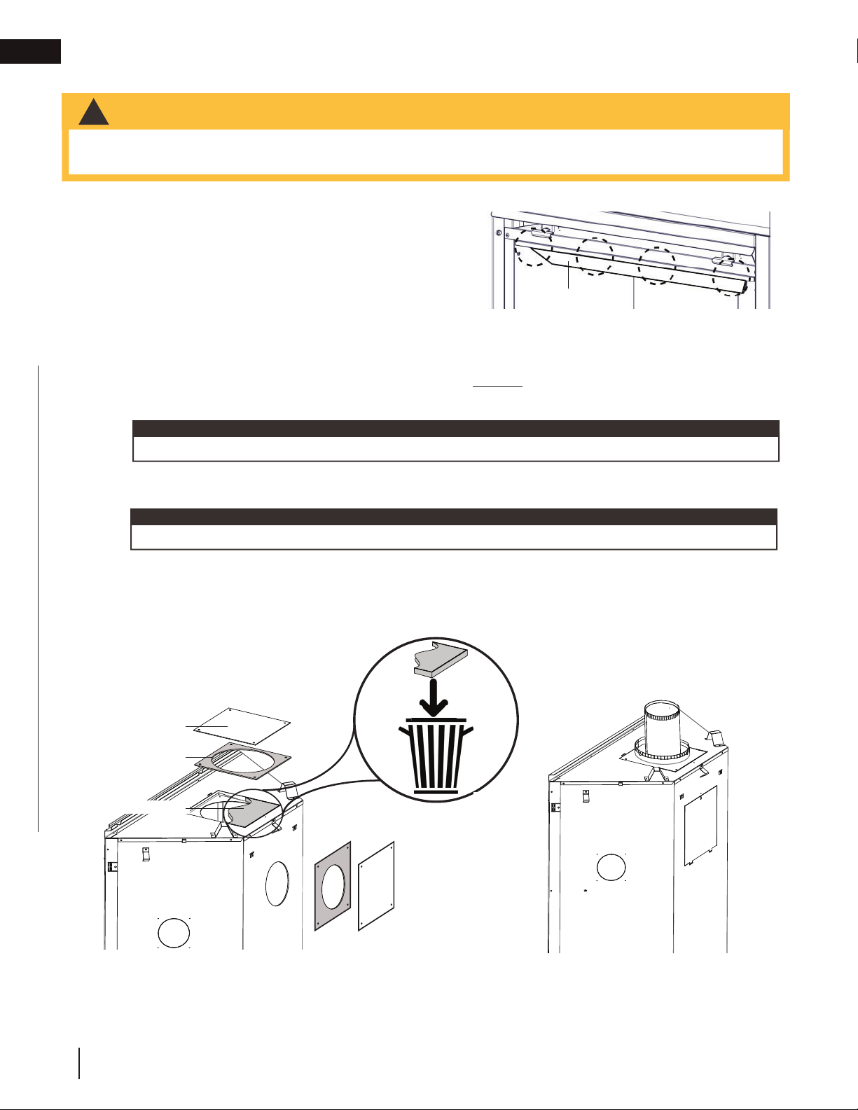
D. Remove the outer cover plate and gasket by removing the 4 screws. Install the outer cover plate and
gasket onto the back of the appliance using the 4 previously removed screws (Fig. 2).
E. Remove the 1 1/2" (38.1mm) thick batt of insulation and discard (Fig. 2).
F. Place the 7" (177.8mm) intake collar and gasket onto the top of the appliance and secure using 4 screws.
G. From inside the fi rebox, install the 4" (101.6mm) exhaust collar with gasket up through the top of the
fi rebox, and secure with the the 4 hex head 3/4" black screws supplied in the manual baggie (Fig. 3).
H. Reinstall the defl ector, glass door, and safety barrier.
2.12 top exit
• Failure to install the cover plate and gasket will cause the appliance to function improperly and can cause
injury or property damage.
!
WARNING
Do not overtighten. The gasket needs only to be snug against the fi rebox.
note:
EXHAUST
FLUE COLLAR
FIG. 3
DEFLECTOR
OUTER
COVERPLATE
GASKET
1 1/2” INSULATION BATT
OUTER
COVERPLATE
GASKET
Fig. 1
Fig. 2
Fig. 3
The screws are packaged in a separate baggie from the manual baggie.
tip:
Loading ...
Loading ...
Loading ...