
Loading ...
Loading ...
Loading ...
W415-2835 / B / 04.05.21
EN
24
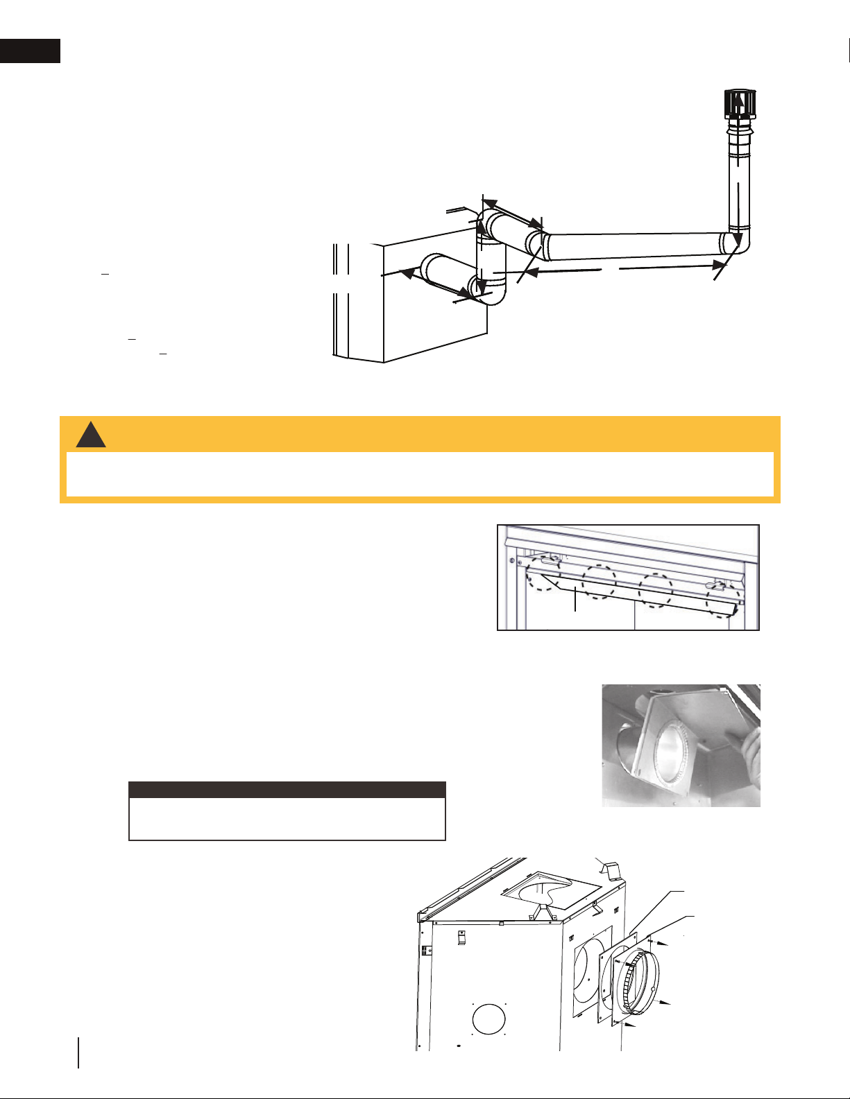
venting requirements
90°
V
1
V
2
H
1
H
2
90°
90°
H
3
45°
Example:
V
1
= 1.5 FT (0.5m)
V
2
= 5 FT (1.5m)
V
T
= V
1
+ V
2
= 1.5FT (0.5m)+ 5FT (1.5m) = 6.5 FT (2m)
H
1
= 1 FT (0.3m)
H
2
= 1 FT (0.3m)
H
3
= 10.75 FT (3.3m)
H
R
= H
1
+ H
2
+ H
3
= 1FT (0.3m) + 1FT (0.3m) + 10.75FT (3.3m) = 12.75FT (3.9m)
H
O
= .03 (three 90° elbows + one 45° elbow - 90°)
= .03 (270° + 45° - 90°) = 6.75 FT (2.1m)
H
T
= H
R
+ H
O
= 12.75FT (3.9m) + 6.75FT (2.1m) = 19.5 FT (5.9m)
H
T
+ V
T
= 19.5FT (5.9m) + 6.5FT (2m) = 26 FT (7.9m)
Formula 1:
H
T
< 3 V
T
3 V
T
= 3FT (0.9m) x 6.5FT (2m) = 19.5FT (5.9m)
19.5FT (5.9m) = 19.5FT (5.9m)
Formula 2:
H
T
+ V
T
< 40 FT (12.2m)
26 FT (7.9m) < 40 FT (12.2m)
Since both formulas are met, this vent confi
g
uration is acce
p
table.
A. Remove the safety barrier and glass front (see "safety barrier
& door removal/installation" section).
B. Remove the contents from the fi rebox and set aside. You will
need the exhaust fl ue collar from the top of the log carton.
C. To ease assembly, remove the four hex head screws
securing the defl ector from inside the top front of the fi rebox
(Fig. 1).
D. Place the gasket (provided) over the 4" (102mm) fl ue collar
assembly and bend along perforation.
E. From inside the fi rebox, insert the 4" (102mm) fl ue collar through the
back of the fi rebox. Install the rear exit shield onto the 4" (102mm)
fl ue collar (see "rear exit shield" section).
F. Secure the fl ue collar assembly, gasket and rear exit shield using
the four hex head 3/8" thread cutting screws (Fig. 2).
G. Reattach the defl ector using the four screws and install
the log set, glass door and safety barrier.
H. Install the 7" (177mm) collar assembly,
complete with gasket, onto the rear
panel around the 4" (102mm) collar
with the screws provided (Fig. 3).
Fig. 2
DEFLECTOR
É
Fig. 1
2.10 rear exit
• Failure to create a seal to the fi rebox with the exhaust collar assembly will cause the appliance to function
improperly and can cause injury or property damage.
!
WARNING
Do not overtighten. The gasket needs only to be
snug against the fi rebox.
note:
INTAKE COLLAR
ASSEMBLY
GASKET
Fig. 3
Loading ...
Loading ...
Loading ...